Article

Study on the Fluid Flow in a Semi-Open-Stream-Poured Beam Blank Continuous Casting Mold with Submerged Refractory Funnels by Multiphase Modeling

College of Materials Science and Engineering, Chongqing University, Chongqing 400045, China
*
Author to whom correspondence should be addressed.
Metals 2016, 6(5), 104; https://doi.org/10.3390/met6050104
Submission received: 9 March 2016 / Revised: 23 April 2016 / Accepted: 26 April 2016 / Published: 17 May 2016

Abstract

:
The flow transport of a 420 × 320 × 90 mm beam blank continuous casting mold that used open-stream pouring combined with submerged refractory funnels was studied. By considering the dynamic similarity, geometric similarity, and air entrapment quantity similarity, a full-size water model was established. Meanwhile, the 3D mathematical models that included three phases were applied. Through the combination of the water model and the mathematical model, the distribution and morphology of the phases in the mold were investigated. The results indicate that bubbles existed in the molten steel due to entrapment and the flow pattern was different from that of the full protection-poured mold. Furthermore, the effects of funnel immersion depth and funnel diameter on the bubbles’ impact depth, funnel’s inside wall shear stress, and overall area of the air/steel interface were discussed. The results provide useful information for the industrial continuous casting process.

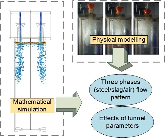
Graphical Abstract

1. Introduction

Beam blank continuous casting is a typical example of the near-net-shape casting, also called “H blank” due to its H-shaped cross section. As the starting material of hot-rolled H beams, beam blank is superior to the other blanks because it provides higher productivity and yield with lower production costs.
In the beam blank continuous casting process, the H shape makes it difficult to apply quick nozzle-change technology in a continuous casting mold and that limits the application of submerged entry nozzles. Generally, open-stream pouring and oil lubrication are used in this situation, such as in some billet molds [1,2]. Nevertheless, it is widely known that the slag in a continuous casting mold helps to ensure even shell solidification and decreases strand surface depressions, cracks, and bleeders [3], which are more common in beam blank continuous casting. Therefore, in the small-size beam blank continuous casting process, open-stream pouring is combined with submerged refractory funnels, as shown in Figure 1, so that the slag can be used and slag entrapment by inlet flow can be prevented [4,5,6]. In this case, a part of the stream is exposed to the air, and the rest is in the submerged refractory funnels. In this article, this type of pouring is termed “semi-open-stream pouring.”
The flow field in the mold plays a crucial role in keeping the casting process stable and controlling the final product quality. Many studies have dealt with such issues in the conventional blank and thin slab continuous casting process, while only few studies related to the beam blank continuous casting case have been conducted. Lee studied the flow pattern of a 480 × 420 × 120 mm beam blank mold using a 3D mathematical model [7]. Chen et al. [8], Seok andYoon [9], and Du et al. [10] obtained the flow field and temperature distribution in beam blank molds using 3D coupled models of fluid flow and solidification. De Santis et al. [11] tested different nozzle geometries with computational fluid dynamics modeling for an industrial beam blank mold and discussed the flow conditions. However, these studies only focused on full-protection pouring conditions and not on open-stream pouring [7,8,9,10,11].
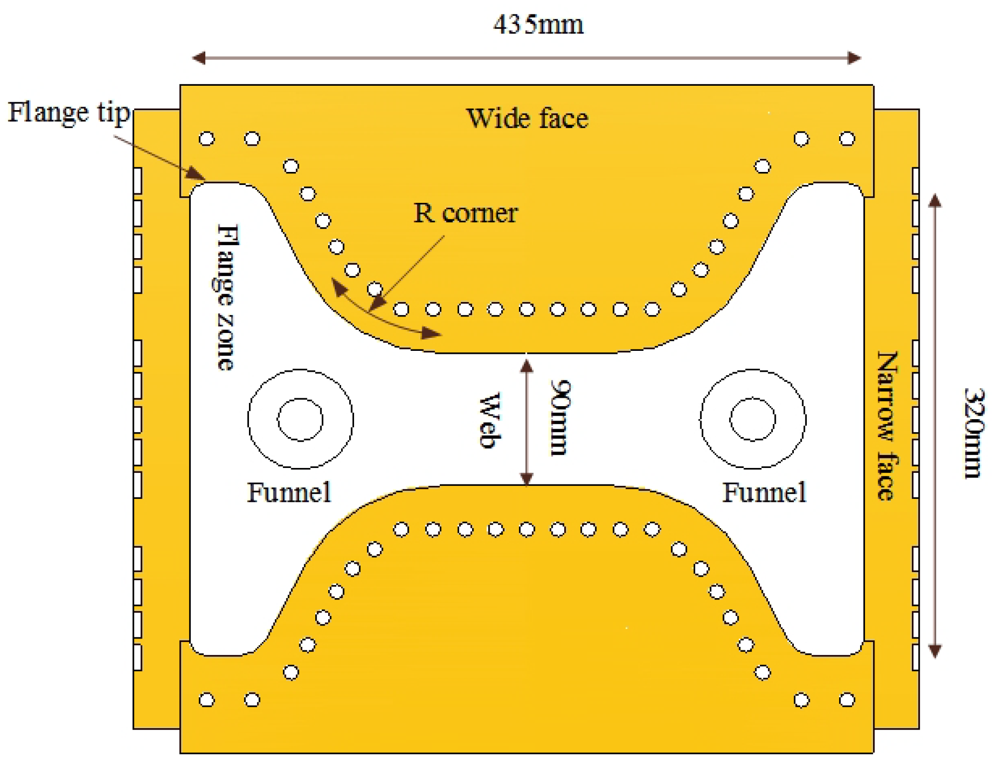
This study focused on the mold using semi-open-pouring by two funnels, because its web and flange region was too narrow to use quick nozzle-change technology. Figure 2 shows the geometry of the mold of interest in the present study. By physical modeling and numerical modeling, the fluid-flow-related phenomena were investigated, including the velocity distribution, air entrapment, and bubble path. Furthermore, the effects of funnel immersion depth and funnel inner diameter on the bubbles’ impact depth, wall shear stress, and air/steel interface area were also examined. The results of this study are considered useful for the modification of the actual continuous casting processes.

2. Physical Modeling

2.1. Experimental Apparatus

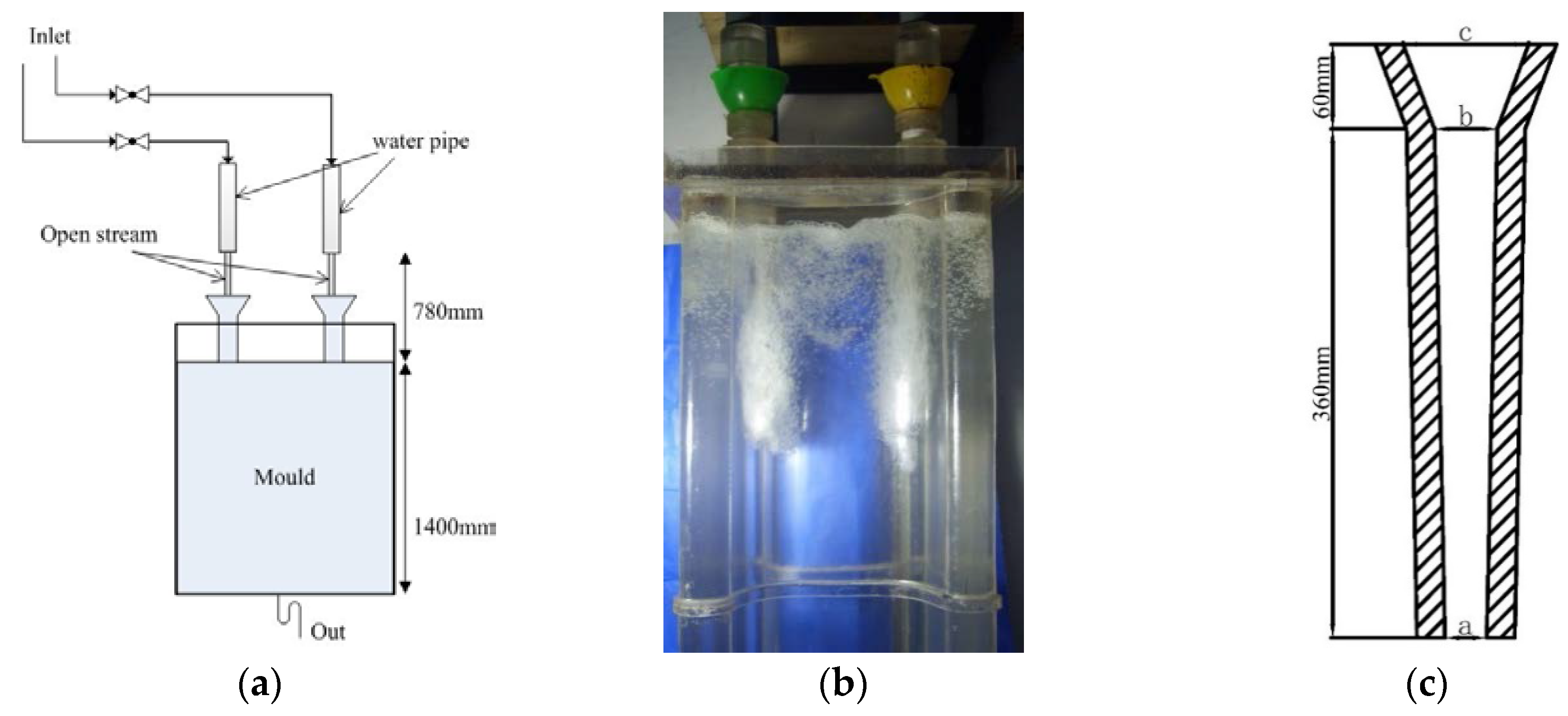
A 1:1 scale model made of transparent plastic was built. Room temperature water was adopted as a substitute for molten steel. The schematic diagram and photograph are shown in Figure 3a,b, respectively. Two different inner diameters (a in Figure 3c) were considered in the design of the submerged refractory funnels. The dimensions and geometries of the submerged refractory funnels are shown in Figure 3c.

2.2. Similarity Conversion Between Water Model and Actual Mold

In the actual pouring process, the molten steel flows into the mold through the air and funnel and brings air into the steel pool. Air, steel, and slag are involved in this process. Theoretically, in order for the results obtained from the water model experiments to be meaningful, the numerical value of relative dimensionless numbers must be the same in the model and in the prototype. Since the flow is gravity driven and has different phases in addition to geometric similarity, the Reynold, Froude, and Weber numbers should be the same, according to the comments of Szekely. The dimensionless groups’ formulas and meanings are listed in Table 1.
However, the phenomena involving surface tension are very complex. Furthermore, bubble/droplet size [12,13], varied viscosities and densities, and droplet emulsification cannot be considered properly by a simple water model. Thus, it is not helpful to match the Weber number without matching many other phenomena as well, which is extremely difficult to achieve [14]. In addition, some studies [15,16,17] have shown that due to the smaller density difference and smaller interface tension difference of the oil/water/bubbles system, emulsion formed in the oil/water/bubbles system is more stable than that formed in the slag/steel/bubbles system. The stable emulsion brings some inconveniences to the experimentation, such as making the water feculent and consuming oil (the substitute for slag) too fast. Considering the fact that the oil/water interface cannot be measured effectively and the emulsion may affect the flow field, the slag was ignored in the water model.
Furthermore, Chen and Tao proposed a similarity criterion En to signify the air entrapment quantity similarity [18], which was confirmed by the numerical method and validated with actual product data. In the beam blank continuous casting mold, which uses semi-open pouring, the bubbles greatly affect the fluid flow, so the En similarity was adopted in the present work. The form of En is expressed as Equation (1).
E n = ρ g H μ σ v
where, ρ is the density of fluid, kg⋅m−3. g is the gravitational acceleration, which is 9.8 m⋅s−2. H is the distance between inlet and the liquid level, m. μ is dynamic viscosity of fluid, kg·m−1⋅s−1. σ is surface tension, mN/m. v is the velocity of inlet, m⋅s−1. The details of the experimental parameters are listed in Table 2. When:
E n steel = E n water
the following relationship holds:
H steel = 1.2 H water
Some previous works have shown that once the flow is fully turbulent, the geometric similarity ensures Reynold’s similarity [14,19]. Checking the Froude similarity under the En similarity, the liquid level inside the funnel was set as the velocity inlet. Because Hsteel is different from Hwater (as Equation (1) reveals), the velocities at the liquid level inside the funnel in the prototype and model are different. The Froude-number relationship between the water model and the prototype is as follows.
1.1 F r water = F r steel
There is a small difference between the water model and the prototype. However, when we compared it with the flow pattern in Volume of Fluid (VOF) models, we found that the result of physical simulation and mathematical simulation achieved a good match. Therefore, it was believed that this difference did not change the fluid flow distribution rule in the mold, and the difference was accepted.

3. Numerical Modeling

Besides the physical model, multiphase numerical models were built up based on the VOF model to understand the flow pattern and the effects of funnel immersion depth and inner diameter quantitatively.

3.1. Fundamental Equations

The 3D continuity and the Navier-Stokes (N-S) Equations, shown in Equations (5) and (6), in Cartesian coordinates, were solved, together with the standard k-ε turbulence model.
Continuity Equation (mass conservation equations)
V = 0
Momentum Conservation Equation (N-S Equations):
ρ ( V ) t + ρ [ V ] V = P + [ μ eff ( V + ( V ) T ) ] + ρ g
Here
μ eff = μ + μ t
μ t = ρ c μ k 2 ε
where, is gradient operator. V is velocity vector. ρ is the density of fluid, kg·m−3. t is time, s. P is the dynamic pressure, Pa. µeff is effective viscosity, kg·m−1·s−1. µ is the molecular viscosity, kg·m−1·s−1. µt is the turbulent (or eddy) viscosity, kg·m−1·s−1. cμ is a constant, 0.09. is divergence operator.

3.2. Turbulence Model

The turbulence kinetic energy (k) and its rate of dissipation (ε) are obtained from the following transport equations:
( ρ k u i ) x i = x i [ ( μ + μ t σ k ) k x i ] + G k ρ ε
( ρ ε u i ) x i = x i [ ( μ + μ ε σ ε ) ε x ε ] + C 1 ε k G k C 2 ε ρ ε 2 k
where, Gk is the generation of turbulence kinetic energy due to the mean velocity gradients, kg·m−1·s−3. xi is the Cartesian coordinate. ui is xi-component of velocity, m·s−1. σk and σε are the turbulent Prandtl numbers for k and ε, respectively. C1ε, C2ε are constants. The values of σk, σε, C1ε and C2ε in standard k-ɛ equations are recommend by Launder and Spalding [20], which is widely used in flow field calculation of the continuous casting process [21,22,23].

3.3. Multiphase Model

The VOF model was employed to solve the steel/slag/air multiphase system. This scheme performs the calculation of the interface between the phases (p and q) present at each cell based on their fraction. The tracking of the interface(s) between the phases is accomplished by the solution of a continuity equation for the volume fraction of one (or more) of the phases. For the qth phase, this equation has the following form:
1 ρ q [ t ( α q ρ q ) + ( α q ρ q u q ) = S α q + p = 1 n ( m ˙ p q m ˙ q p ) ]
where m ˙ q p is the mass transfer from phase q to phase p and m ˙ p q is the mass transfer from phase p to phase q. n is the number of phases (here it is 3). S α q is a number which can defined by the user, which is 0 in this study.
The explicit approach standard finite-difference interpolation scheme was applied to the volume fraction values that were computed at the previous time step. This scheme has the following form:
α q t + 1 ρ q t + 1 α q t ρ q t Δ t V + f ( ρ q U f t α q , f t ) = [ p = 1 n ( m ˙ p q m ˙ q p ) + S α q ] V
where t + 1 is the index for the new (current) time step, t is the index for the previous time step, αq,f is the face value of the qth volume fraction, computed from the QUICK scheme, V is the volume of the cell and Uf is the volume flux through the face, based on normal velocity.

3.4. Model Implementation

As the grid size decreases, the computational accuracy increases, but the computational time also increases. This work, referring to several multiphase modeling cases [2,24], has a grid with 789,000 structured cells. The grid was created by GAMBIT, as shown in Figure 4a. The grid was performed by an Intel(R) core(TM) i7-3770k processor and an i5-m520, and the same flow pattern was obtained in both cases. Then, all simulations were performed in workstations with Intel(R) core(TM) i7-3770k processors and 16 GB RAM memory.
The governing equations were discretized in FLUENT using an implicit, first-order upwinding scheme and the SIMPLEC algorithm for pressure-velocity coupling. The convergence criterion was obtained when the residuals of the output variables reached values equal to or smaller than 1 × 10⁻⁶. The time step was 0.0003 s. Under typical pouring conditions, the calculation time was about 10 actual days, for a total model time of 40 s.

3.5. Modeling Conditions

The air, steel, and slag were assumed to have Newtonian behavior without changes in density. Simulations were developed under unsteady state and isothermal conditions. The curvature of the casting machine was ignored, and the 1/4 mold was modeled for symmetry to improve the efficiency of the research. The grid, model dimensions, and initial phase placement are shown in Figure 4. The effective length of the mold was 0.7 m, but the pool was deepened to 1.5 m to consider the effect of the pool beyond the mold.
Inlets and outlet were defined as uniform velocity faces based on the conservation of mass. A pressure inlet condition was applied at the air faces (P = 101325 Pa) to model the effects of a system open to the atmosphere. The physical properties of fluid and the simulation parameters are tabulated in Table 3.

4. Results and Discussion

4.1. Flow Field in Molten Steel Region

The flow field in the beam blank continuous casting mold was studied in the case in which funnels with 40 mm inner diameter and 70 mm immersion depth were used.
Figure 5 shows the flow pattern at different times in the physical experiment. These pictures display that once the tracer arrived at a certain impact depth the tracer was biased. Then, the tracer tended to move upward. Firstly, the tracer reached the liquid level near the funnels and then spread to other places, because the fluid flow was stirred by bubbles with different rising trajectories [25,26,27]. The large effect of the bubbles on the fluid flow and the flow’s movement is shown in Figure 5.
On the other hand, the velocity vector diagram was obtained from mathematical modeling, as shown in Figure 6. These pictures provide more information on the flow in the perturbed zone of Figure 5. There are two pairs of vortices in both the web region and flange region. In the web, there are two big vortices below the funnel’s bottom and two small vortices in the area between the funnel’s bottom and the slag/steel interface. In the flange region, a pair of big vortices appears on each side of the funnel. Two small vortices are on top of each big vortex, and their trajectories are less clear than those in the web. This could be the cause of the more regular shape, like a slab, which is helpful for obtaining well-ordered flow trajectories. Furthermore, the centers of the small vortices in the flange region are closer to the slag/steel interface than those in the web region.
Moreover, compared with molds in which two straight submerged entry nozzles were used with a protected stream [6,7], which also had eddies in the web region and flange region, the vortices obtained when semi-open pouring was used have completely different movement. This result provides useful information to elucidate the actual beam blank mold process.

4.2. Distribution and Morphology of Bubbles

The distribution and morphology of bubbles were studied in the case in which funnels with 40 mm inner diameter and 70 mm immersion depth were used.
Figure 7 shows the transient bubbles’ morphology and bath level oscillation. These pictures show that air is entrapped by inlet flow, bubbles exist in the area above a certain impact depth, and the distribution and size of bubbles is random and hard to control. Figure 7b shows the flow and bubble pattern in the physical model. Regarding the size of the bubbles in Figure 7, the large bubbles cannot be seen in the physical modeling. The difference in maximum bubble size between steel-gas and water-gas has been studied in [16,28], and the differences in density and interfacial tension lead to bigger bubbles in liquid steel. For both types of modeling, most bubbles tend to escape from the area near the funnels, and the liquid level around the funnels is raised.
Figure 8 shows the typical velocity vector diagrams of slag interfaces with air and steel. It must be noted that the level oscillations are very different each time, which is due to the inertial forces of the turbulent steel stream together with the random nature of the bubbles exiting through the free surface of the steel. Figure 8b,c illustrates the typical morphology of a big bubble entering a slag layer, while Figure 8c through (e) display the shape and most frequent distribution of the channels formed by big bubbles.
Figure 8b,c shows a big bubble going into a slag layer. The top of the bubble at the beginning of the slag layer (Figure 8b) has a higher speed than that at the middle of the slag layer (Figure 8c) due to the viscous force.
Because of the non-uniform gas flow rate at different places on the steel/slag interface, small bubbles float in the slag, and some big bubbles form channels in the slag layer, as shown in Figure 8d,e. This is similar to the results of Hahn [29], obtained from a physical model in which bubbles broke the meniscus as a consequence of the open pouring and subsequent entrapment.
Moreover, Figure 8 demonstrates that bigger bubbles tend to float near the funnels but not the flange tips or the middle region of the web. This phenomenon occurs because big bubbles have higher rising speeds than small bubbles [30]. The big bubbles have a high speed that allows them to get into the slag layer, but the small bubbles are more likely to be pushed to the flange tip or web by flows before they have time to get into the slag layer. These small bubbles may also be entrapped at the meniscus, especially if large oscillation hooks or large level fluctuations occur [31].

4.3. Effect of Funnel Immersion Depth

Three immersion depths were studied by using funnels with 40 mm inner diameter. The flow patterns at varied funnel immersion depths in the physical model are shown in Figure 9. The bubbles’ impact depths are indicated by lines in each picture. Figure 9 indicates that the bubbles’ impact depth increases as the funnel immersion depth increases. Although semi-open pouring was used and there was a remarkable quantity of bubbles in the fluid flow, the funnels also showed a guiding ability. However, the difference between Figure 9b,c was smaller than that between Figure 9a,b.
Under a certain bubble size, a longer float distance leads to a higher speed of bubbles at the slag/steel interface, which can increase the fluctuation of the meniscus. As discussed in [11], when a criterion is reached relating tangential velocities at the steel-slag interface, slag entrainment occurs. Meanwhile, a longer floating distance means that the air stays in contact with the liquid steel longer, which leads to more steel re-oxidation. Shallower funnel immersion depths lead to shallower bubble impact depths, which is believed to be good for stable meniscus oscillation and anti-oxidation.
Under 70 mm and 90 mm immersion depths, the total areas of the air/steel interface at ten random times were obtained from mathematical simulation, and they are plotted in Figure 10. The total area of the air/steel interface is used to determine where re-oxidation possibly happens. Figure 10 shows that most sample values in the 90 mm case are bigger than those in the 70 mm case. The average values of the air/steel interface area at 70 mm and 90 mm funnel immersion depths are 0.0378 m2 and 0.0429 m2, respectively.
A bigger air/steel interface area means larger contact areas between air and molten steel, which provides more opportunities for steel re-oxidation. As mentioned above, the re-oxidation degree of steel with a 90 mm funnel immersion depth was slightly worse than that with a 70 mm funnel immersion depth. This result also verifies the inference of Figure 9. In the present work, a funnel immersion depth of 70 mm is suggested to be optimal for further studies.

4.4. Effect of Funnel Inner Diameters on Possibility of Re-Oxidation and Refractor Erosion

The 40 mm and 30 mm inner diameter funnels with a 70 mm funnel immersion depth were studied. As a note, a clear difference in bubbles’ impact depths cannot be achieved from physical simulations, so the results of the mathematical simulation are mainly discussed here.
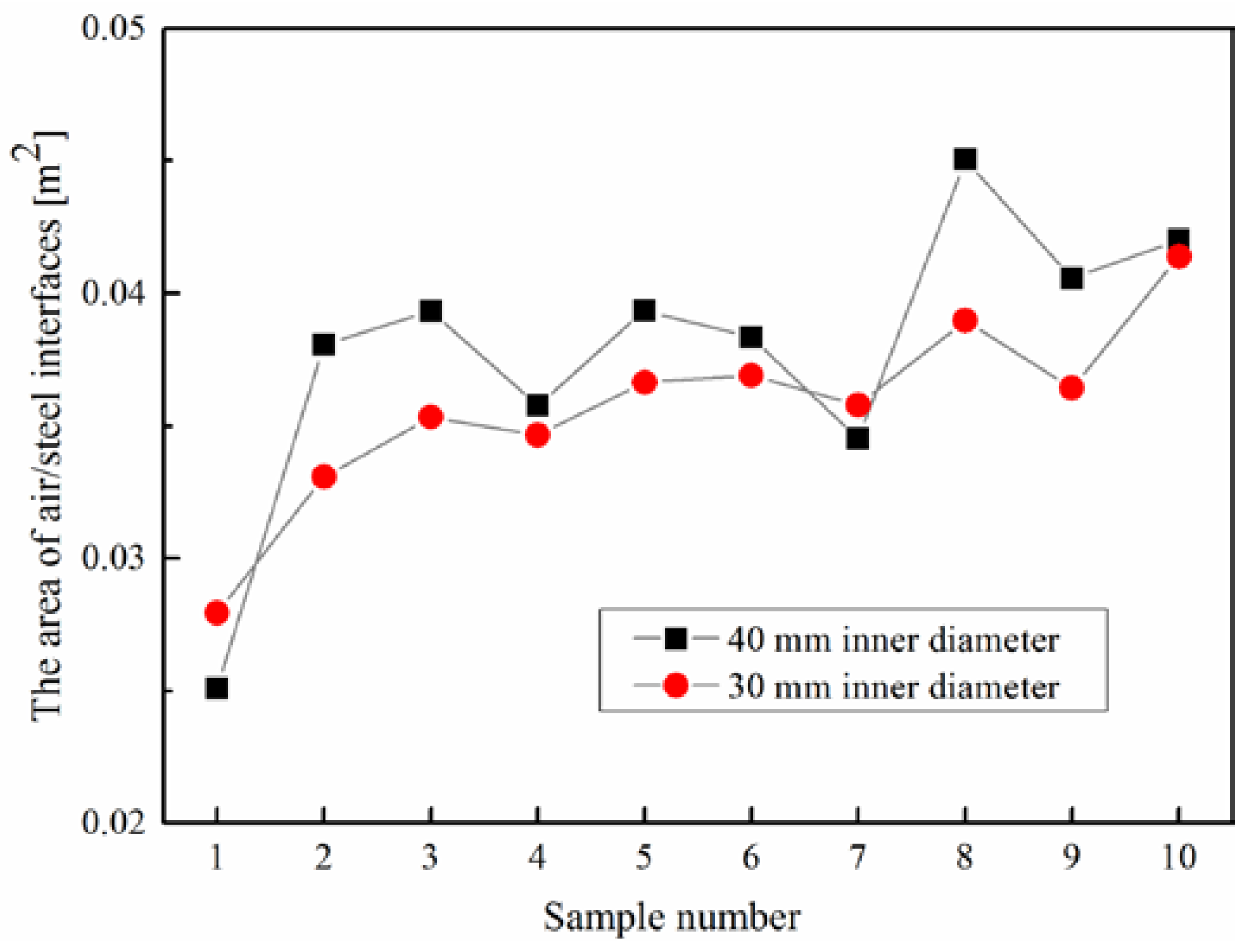
Figure 11 shows the result of the overall air/steel interface area. There is a small difference between the two cases: the average area value in the 30 mm diameter case was 0.0357 m2 and that in the 40 mm inner diameter case was 0.0378 m2. Only a 0.2% difference was achieved between the two cases due to the small difference in the bubbles’ impact depths in the physical modeling. In addition, this difference indicates that, compared with the funnel immersion depth, funnel inner diameter is not the key factor affecting the overall air/steel interface area and bubbles’ impact depth.
In addition, the shear stress distribution of the funnel’s inside wall was investigated in this step. As shown in Figure 12, inside the funnel, the funnel wall is washed by high-speed flow. It is known that refractory erosion is one of the reasons for inclusions. Although the shear stress distributions are different at different times, the maximum shear stress distribution appeared mainly on the wall near the funnel bottom.
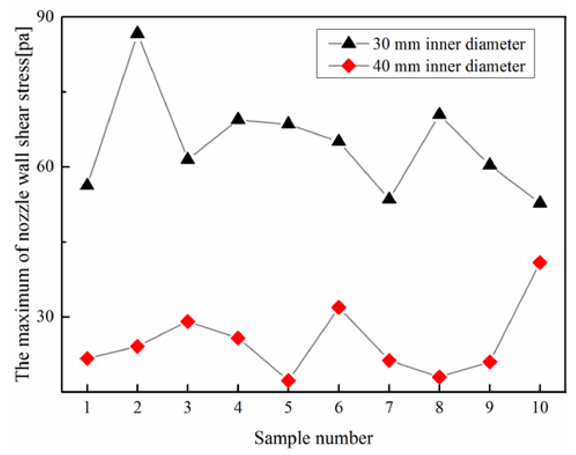
Figure 13 shows the maximum shear stress of the funnel’s inside wall. Ten samples obtained from each alternative at varied times were employed. Obviously, the maximum shear stress of the funnel with the 30 mm inner diameter is bigger than that with the 40 mm inner diameter in the chart. The average value of the 40 mm inner diameter case is 25.11 Pa, while the average value of the 30 mm inner diameter case is 64.48 Pa. Sambasivam [32] studied the effects of inner wall shear stress on avoiding inclusion build-up inside the nozzle. Sambasivam stated that relatively higher shear stress values can help in reducing the clogging tendency during the initial periods of inclusion build-up. However, he claimed that when clogging exists, this anti-clogging efficiency is difficult to predict. On the other hand, when the shear stress is larger in a certain area, the shear force is larger, and bigger and more inclusions are detached by the larger shear force. Thereby, the level of harmful macroinclusions in the cast products increases.
From the overall air/steel interface area perspective, the smaller inner diameter is helpful for decreasing the overall area of the air/steel interface to some degree. However, when funnel clogging starts to increase, the bigger inner diameter has obvious lower wall shear stress, which may lead to smaller and fewer inclusions detaching from the funnel. In addition, considering the unstable situation in the actual process, the bigger inner diameter is easy to center for the inlet stream to make sure the stream hits the pool but not the funnel wall directly. In most situations, the bigger inner diameter has better performance.

5. Conclusions

The flow field in a beam blank continuous casting mold, which used semi-open-pouring with two submerged refractory funnels, was studied by physical modeling and numerical modeling, and the following conclusions were obtained:
(1) Some recirculating domains can be observed in the web region and flange region of molten steel, and the sharpness of the recirculating domains is affected by the bubbles and the geometry of the region. The flow pattern in the beam blank mold that used semi-open pouring with two submerged funnels is different from that in the mold that used fully protected pouring with two strained submerged entry nozzles.
(2) Bubbles are entrained due to unprotected pouring. A larger percentage of air floats to the liquid surface near funnels, and then the channels formed by the high gas flow rate are more likely to appear on the liquid surface near the funnels. Small bubbles tend to appear on the web region and flange tip because of their lower rising speed compared to that of big bubbles.
(3) Funnel immersion depth is the key factor that affects bubble impact depth and overall air/steel interface area. The trend of bubble impact depth is consistent with that of overall air/steel interface area. Both of them increase with the funnel immersion depth. The shallower funnel immersion depth helps to reduce the possibility of re-oxidation and fluctuation of the meniscus.
(4) Funnel inner diameter has a small effect on the bubble impact depth and air/steel interface area. On the other hand, funnel inner diameter affects wall shear stress at the submerged refractory funnel’s inner wall. As the funnel’s inner diameter increases, the funnel’s inner wall shear stress decreases.

Acknowledgments

This work was financially supported by the Natural Science Foundation of Chongqing (project No. cstc2013jcyjA50005) and the Natural Science Foundation of China (NSFC, project No. 51374260 and project No. 51504048). We also would like to acknowledge CISDI Engineering Co., Ltd. (Chongqing, China) for collaboration.

Author Contributions

Dengfu Chen and Leilei Zhang conceived and designed the experiments; Leilei Zhang, Zhihua Dong, Huabiao Chen and Huangyun Wei performed the experiments; Leilei Zhang, Mujun Long, Zhihua Dong analyzed the data; Leilei Zhang and Mujun Long wrote the paper.

Conflicts of Interest

The authors declare no conflict of interest.

References

  1. Ludlow, V.; Normanton, A.; Anderson, A.; Thiele, M.; Ciriza, J.; Laraudogoitia, J.; van der Knoop, W. Strategy to minimise central segregation in high carbon steel grades during billet casting. Ironmak. Steelmak. 2005, 32, 68–74. [Google Scholar] [CrossRef]
  2. Machado-Lopez, M.M.; Ramos-Banderas, J.A.; Torres-Alonso, E.; Barreto, J.J.; Garcia-Hernandez, S. Multiphase modelling of liquid steel transfer from tundish to curved billet mould by open stream and equipped with SEN. Ironmak. Steelmak. 2013, 40, 326–334. [Google Scholar] [CrossRef]
  3. Pinheiro, C.; Samarasekera, I.; Brimacombe, J.; Howes, B.; Gussias, O. Mould heat transfer and continuously cast billet quality with mould flux lubrication Part 2 quality issues. Ironmak. Steelmak. 2000, 27, 144–159. [Google Scholar] [CrossRef]
  4. Foundation, A.S.; Cramb, A.W. The Making, Shaping and Treating of Steel: Casting Volume; AISE Steel Foundation: Warrendale, PA, USA, 2003. [Google Scholar]
  5. Hibbeler, L.C.; Xu, K.; Thomas, B.G.; Koric, S.; Spangler, C. Thermomechanical modeling of beam blank casting. Iron Steel Technol. 2009, 6, 60–74. [Google Scholar]
  6. Su, S.; Sun, W.; Pan, G. High Efficient Energy-Saving Construction Steel: Hot-Rolled h-Beam; Metallurgical Industry Press: Beijing, China, 2009; p. 508. (In Chinese) [Google Scholar]
  7. Lee, J.E.; Yeo, T.J.; Oh, K.H.; Yoon, J.K.; Yoon, U.S. Prediction of cracks in continuously cast steel beam blank through fully coupled analysis of fluid flow, heat transfer, and deformation behavior of a solidifying shell. Metall. Mater. Trans. A 2000, 31, 225–237. [Google Scholar] [CrossRef]
  8. Chen, W.; Zhang, Y.-Z.; Zhu, L.-G. Three-dimensional FEM study of fluid flow in mould for beam blank continuous casting: Influence of straight through conduit type SEN. Ironmak. Steelmak. 2012, 39, 551–559. [Google Scholar] [CrossRef]
  9. Seok, Y.J.; Yoon, J.K. The effect of casting conditions on the formation of longitudinal surface crack in the beam blank caster. Met. Mater. Int. 2002, 8, 543–550. [Google Scholar]
  10. Du, Y.P.; Yang, J.W.; Shi, R. Effect of submerged entry nozzle (SEN) parameters and shape on 3-D fluid flow in mould for beam blank continuous casting. Acta Metall. Sini. 2004, 17, 705–712. [Google Scholar]
  11. De Santis, M.; Cristallini, A.; Rinaldi, M.; Sgro, A. Modelling-based innovative feeding strategy for beam blanks mould casting aimed at as-cast surface quality improvement. ISIJ Int. 2014, 54, 496–503. [Google Scholar] [CrossRef]
  12. Minchaca, J.I.; Castillejos, A.H.; Acosta, F.A. Size and velocity characteristics of droplets generated by thin steel slab continuous casting secondary cooling air-mist nozzles. Metall. Mater. Trans. B 2011, 42, 500–515. [Google Scholar] [CrossRef]
  13. De Leon, M.; Castillejos, A.H. Physical and mathematical modeling of thin steel slab continuous casting secondary cooling zone air-mist impingement. Metall. Mater. Trans. B 2015, 46, 2028–2048. [Google Scholar] [CrossRef]
  14. Chaudhary, R.; Rietow, B.T.; Thomas, B.G. Differences between physical water models and steel continuous casters: A theoretical evaluation. In Proceedings of the Materials Science & Technology 2009 Conference and Exhibition (MST9), Pittsburgh, PA, USA, 25–29 October 2009.
  15. Ashrafizadeh, S.; Motaee, E.; Hoshyargar, V. Emulsification of heavy crude oil in water by natural surfactants. J. Pet. Sci. Eng. 2012, 86, 137–143. [Google Scholar] [CrossRef]
  16. Christov, N.C.; Ganchev, D.N.; Vassileva, N.D.; Denkov, N.D.; Danov, K.D.; Kralchevsky, P.A. Capillary mechanisms in membrane emulsification: Oil-in-water emulsions stabilized by tween 20 and milk proteins. Colloid Surf. A 2002, 209, 83–104. [Google Scholar] [CrossRef]
  17. Xie, H.; Yapa, P.D.; Nakata, K. Modeling emulsification after an oil spill in the sea. J. Mar. Syst. 2007, 68, 489–506. [Google Scholar] [CrossRef]
  18. Chen, J.; Tao, S.; Sun, T. Research of air entrainment quantity of steel flow. Chem. Metall. 1985, 4, 132–138. (In Chinese) [Google Scholar]
  19. Zhang, L.; Chen, D.; Liu, Q.; Zhang, M.; Xie, X.; Luo, D. Optimizing of flow control devices in a single strand continuous casting tundish. Adv. Mater. Res. 2011, 284, 1209–1215. [Google Scholar] [CrossRef]
  20. Launder, B.E.; Spalding, D.B. Lectures in Mathematical Models of Turbulence; Academic Press: Cambridge, MA, USA, 1972. [Google Scholar]
  21. Ha, M.Y.; Lee, H.G.; Seong, S.H. Numerical simulation of three-dimensional flow, heat transfer, and solidification of steel in continuous casting mold with electromagnetic brake. J. Mater. Process. Technol. 2003, 133, 322–339. [Google Scholar] [CrossRef]
  22. Lai, K.; Salcudean, M.; Tanaka, S.; Guthrie, R. Mathematical modeling of flows in large tundish systems in steelmaking. Metall. Trans. B 1986, 17, 449–459. [Google Scholar] [CrossRef]
  23. Shamsi, M.; Ajmani, S. Analysis of mould, spray and radiation zones of continuous billet caster by three-dimensional mathematical model based on a turbulent fluid flow. Steel Res. Int. 2010, 81, 132–141. [Google Scholar] [CrossRef]
  24. Laux, H.; Johansen, S.T. A CFD analysis of the air entrainment rate due to a plunging steel jet combining mathematical models for dispersed and separated multiphase flows. In Proceedings of the Symposium on Fluid Flow Phenomena in Metals Processing at TMS Annual Meeting, San Diego, CA, USA, 28 February–4 March 1999.
  25. Zenit, R.; Magnaudet, J. Path instability of rising spheroidal air bubbles: A shape-controlled process. Phys. Fluids 2008, 20, 061702. [Google Scholar] [CrossRef]
  26. Veldhuis, C.; Biesheuvel, A.; van Wijngaarden, L. Shape oscillations on bubbles rising in clean and in tap water. Phys. Fluids 2008, 20, 040705. [Google Scholar] [CrossRef]
  27. Tomiyama, A.; Celata, G.P.; Hosokawa, S.; Yoshida, S. Terminal velocity of single bubbles in surface tension force dominant regime. Int. J. Multiph. Flow 2002, 28, 1497–1519. [Google Scholar] [CrossRef]
  28. Szekely, J. Fluid Flow Phenomena in Metals Processing; Academic Press, Inc.: New York, NY, USA, 1979. [Google Scholar]
  29. Hahn, I.; Neuschutz, D. Ejection of steel and slag droplets from gas stirred steel melts. Ironmak. Steelmak. 2002, 29, 219–223. [Google Scholar] [CrossRef]
  30. Liu, L.; Yan, H.J.; Zhao, G.J. Experimental studies on the shape and motion of air bubbles in viscous liquids. Exp. Therm. Fluid Sci. 2015, 62, 109–121. [Google Scholar] [CrossRef]
  31. Zhang, L.F.; Yang, S.B.; Cai, K.K.; Li, J.Y.; Wan, X.G.; Thomas, B.G. Investigation of fluid flow and steel cleanliness in the continuous casting strand. Metall. Mater. Trans. B 2007, 38, 63–83. [Google Scholar] [CrossRef]
  32. Sambasivam, R. Clogging resistant submerged entry nozzle design through mathematical modelling. Ironmak. Steelmak. 2006, 33, 439–453. [Google Scholar] [CrossRef]
Figure 1. Schematic illustration (a) and photo (b) of beam blank mold using semi-open pouring combined with submerged refractory funnels.
Metals 06 00104 g001
Figure 2. Schematic illustration of 435 mm × 320 mm × 90 mm beam blank mold.
Metals 06 00104 g002
Figure 3. (a) Sketch of physical model; (b) photo of physical model; and (c) sketch of submerged refractory funnel.
Metals 06 00104 g003
Figure 4. Grid (a); calculated domain schematic (b); and conditions of initial distribution for simulated phases (c).
Metals 06 00104 g004
Figure 5. Flow pattern in mold in narrow face view (left) and wide face view (right): (a) 0 s; (b) 0.6 s; (c) 1.2 s; (d) 3.4 s.
Metals 06 00104 g005aMetals 06 00104 g005b
Figure 6. Flow pattern obtained from outside of mold by mathematical modeling: (a) narrow face view; (b) wide face view.
Metals 06 00104 g006
Figure 7. Air bubbles and bath level oscillation of mathematical modeling (a) and physical modeling (b).
Metals 06 00104 g007
Figure 8. Typical velocity vectors of slag/steel interface and slag/air interface. (a) sketch of slag/steel interface and slag/air interface; (b) shape of slag/steel interface and slag/air interface with a big bubble began getting into the slag layer; (c) shape of slag/steel interface and slag/air interface with a big bubble at a later time than (b); (d) shape of slag/steel interface and slag/air interface with a little sized bubble and a channel; (e) shape of slag/steel interface and slag/air interface with a channel.
Metals 06 00104 g008aMetals 06 00104 g008b
Figure 9. Flow patterns at varied funnel immersion depths: (a) 70 mm; (b) 90 mm; (c) 110 mm.
Metals 06 00104 g009
Figure 10. Overall area of air/steel interface at varied immersion depths.
Metals 06 00104 g010
Figure 11. Overall area of air/steel interfaces in varied nozzle inner diameters.
Metals 06 00104 g011
Figure 12. Distribution of wall shear stress (Pa) at 30 mm inner diameter funnel’s inner wall.
Metals 06 00104 g012
Figure 13. Maximum values of nozzle wall shear stress at varied inner diameters.
Metals 06 00104 g013
Table 1. Dimensionless groups.
GroupFormulaNomenclatureMeaning
Reynolds number R e = L u ρ / μ L characteristic length
μ fluid viscosity
σ surface tension
u fluid velocity
ρ fluid density
Inertial force/viscous force
Froude number F r = u 2 / ( g L ) Inertial force/gravitational force
Weber number W e = L u 2 ρ / σ Inertial force/surface tension force
Table 2. Physical properties of fluids and parameters of water model.
Items/UnitPrototypeWater Model
Density/kg·m−37038998.2
Viscosity/m2·s−18.7 × 10−710.1 × 10⁻⁷
Flow rate/m3·h−15.8946.190
Table 3. Simulation conditions and properties.
Items/UnitValuesItems/UnitValues
Density of steel/kg·m−37080Steel/air Interfacial tension/N·m−11.8
Density of slag/kg·m−32800 Steel/slag Interfacial tension/N·m−11.2
Density of air/kg·m−31.225 Slag/air Interfacial tension/N·m−10.2
Viscosity of steel/Pa·s0.0062Casting speed/m·min−11.3
Viscosity of slag/Pa·s0.2Layer slag thickness/mm25
Viscosity of air/Pa·s0.000001Funnel immersion depth/mm70, 90, 110