Abstract
This work reports on experimental and numerical results of the gray-to-white transition (GWT) during solidification of a hypereutectic gray cast iron (GCI) in a casting test using a stub-to-carbon (STC) connection assembly. Since in this process non-uniform cooling rates are produced, the mechanical properties are expected to spatially vary due to the development of different microstructures along the thimble. The twin aims of this work were to (1) experimentally validate the GWT prediction capabilities of the microstructural model proposed earlier by the authors in the rodding process of a hypereutectic GCI-STC, and (2) estimate, from the numerically obtained microstructure and ultimate tensile strength (UTS), the local hardness of the alloy after the numerical predictions of the microstructure were experimentally validated. To this end, the final microstructure at different points of the thimble and the hardness profile along its radial direction were measured for validation purposes. Moreover, this rodding process was simulated using an extension of a thermal microstructural model previously developed by the authors and the GWT was superimposed on that simulation. The computed results encompass cooling curves, the evolution of gray and white fractions, eutectic radii and densities and, in addition, the hardness profile. A detailed discussion of the experimental and numerical results is presented. Finally, the computed GWT was found to adequately reproduce the experimental data.
1. Introduction
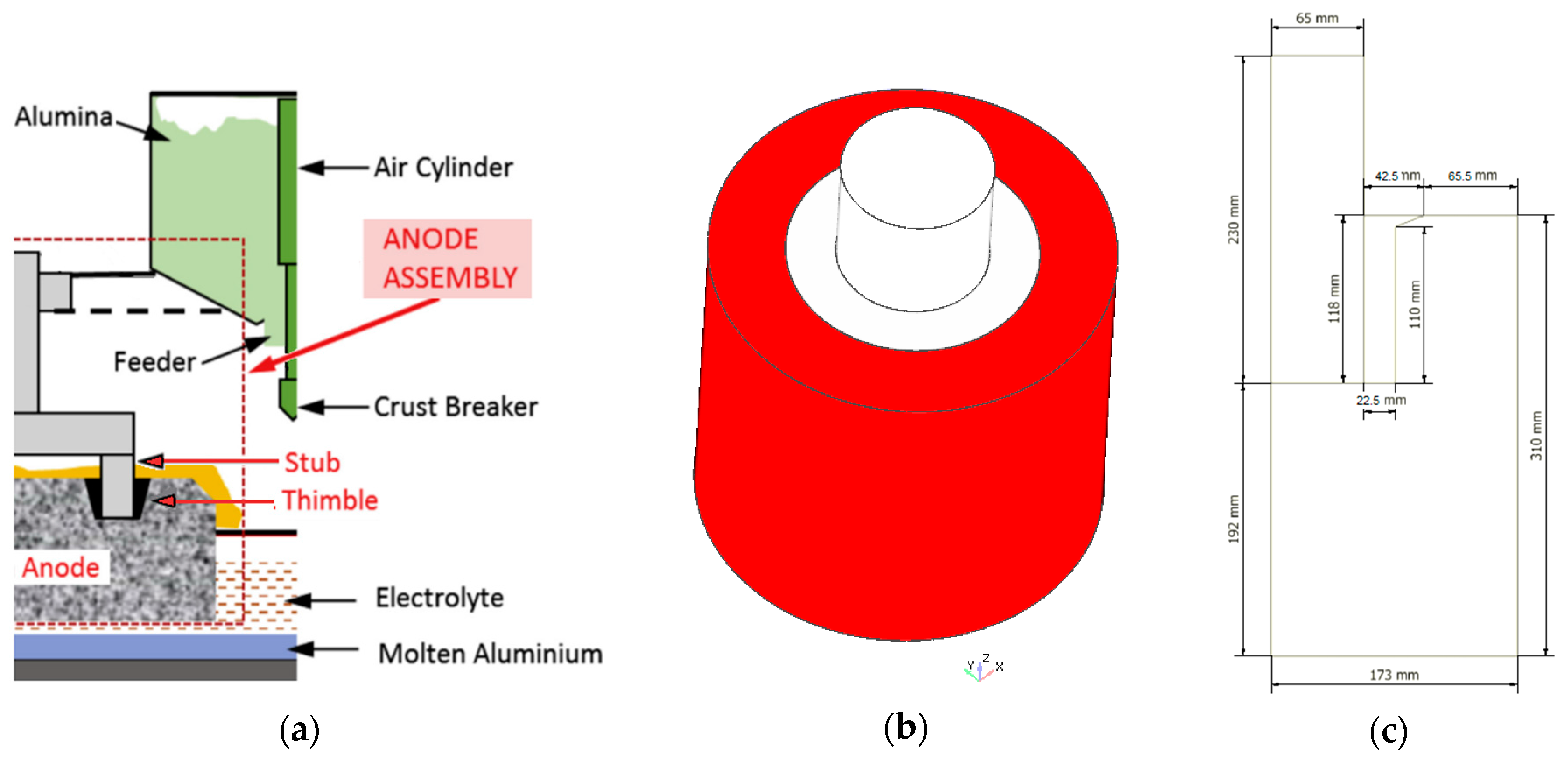
The Hall-Héroult smelting process is the most widely used method to reduce alumina to aluminum via electrolysis. Due to the large amounts of electrical energy involved to overcome the strong chemical bond existing between the aluminum and oxygen present in the raw material, one of the most important factors affecting the efficiency of the process is related to the total cell voltage drop caused by the electrical resistances of the various materials as well as the several electrical connections encountered in the current flow path. Therefore, advanced analysis tools to assist primary aluminum smelters achieve substantial savings in energy efficiency and reduced greenhouse emissions are currently of interest. In particular, some recent studies [1,2,3,4] have focused on a gray cast iron (GCI) thimble, which is part of what is known in the industry as the stub-to-carbon connection (STC), Figure 1. This is an electrical connection in the anode assembly between the stub and the carbon anode (C-anode) which are linked by the thimble, and is responsible for energy loss from Joule heating due to an imperfect contact that exists at the anode-thimble interface. This imperfect contact is associated with an air gap that forms during the rodding process when the solidifying thimble contracts and shrinks onto the stub. This occurs in spite of the fact that thimbles made of hypereutectic GCI have, compared to other alloys, improved global shrinkage mitigation due to expansion during solidification, as well as a higher electrical conductivity and thermal conductivity at high temperatures that benefit the smelting aluminum operation.
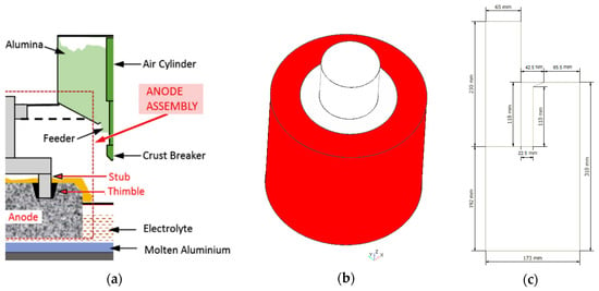
Figure 1.
(a) Hall-Héroult electrolytic cell [3] (Reproduced with permission from Gunasegaram and Molenaar [3], Elsevier Ltd., 2013); (b) stub-to-carbon (STC) assembly: stub (light gray), thimble (dark gray) and carbon anode (red), Longitudinal axis (blue arrow) and radial axis (red arrow); (c) Half slice geometry used for the simulations, dimensions in mm, longitudinal-radial plane.
Thermal-electrical-mechanical finite element simulations of GCI-STC during the cell operation [1,2,3] and rodding process [2,3,4] have been recently performed. Specifically, the analysis of the rodding process carried out in these works was focused on the prediction of: (a) spatially-varying room temperature mechanical properties of the thimble, owing to the fact that they are strongly affected by microstructure and (b) its cracking tendency during the solidification stage. In this context, the estimation of the mechanical properties was based on correlations depending on the resulting microstructure in terms of phases which were computed, in turn, via assumed relationships between alloy composition and solidification rates. Due to the fast solidification that takes place in this problem, white iron appears in some regions of the thimble. Since the thermomechanical properties of gray and white irons are noticeably different, the proper description of the gray to white transition (GWT) is therefore relevant in this application: when the surface has white cast iron, the hardness of the surface increases and becomes less malleable, so would conform less with the surface of the carbon anode, consequently increasing the contact electrical and thermal resistances. The need for a more accurate determination of the microstructure evolution during the GCI solidification via multiscale models accounting for nucleation and growth of the various phases present in the process has long been recognized towards achieving a robust and realistic estimation of the final mechanical properties, e.g., hardness and strength, of a cast part [3]. These two relevant aspects, i.e., GWT prediction and mechanical properties estimation of GCIs, are separately discussed below.
The GWT takes place when the stable graphite and metastable cementite eutectics competitively nucleate and grow during cast iron solidification. Characterization of this transition is usually done though chill testing that allows identification of three regions in a chill sample: gray, mottled and white. The chilling tendency (CT) of a given cast iron part, i.e., its susceptibility for the GWT, is a well-known index to determine its subsequent performance in diverse applications: high CT cast irons develop white or mottled regions with high hardness and excellent wear properties, whilst small CT cast irons favor the formation of gray zones with lower hardness and good machinability. Due to this, the effects of chemical composition and inoculation practice on the CT have been particularly addressed, both experimentally and theoretically ([5,6,7,8,9], and references therein). Moreover, the influence of some alloying elements on the competition between the gray and white eutectics has been studied in directional solidification experiments by measuring the associated transition velocities [10,11]. A heat-transfer/microstructural model has been developed to predict the evolution of proeutectic austenite, white iron eutectic, and gray iron eutectic during solidification of hypoeutectic GCI where the phase distribution predicted with the model has been compared to the measured phase distribution inferred from the variation in hardness within the casting sample [12]. The modeling of the competition between the white and gray iron microstructures and between the columnar and equiaxed morphologies in a hypoeutectic GCI has been proposed and applied to calendar rolls where the phase fractions profiles were experimentally validated [13,14]. Hypoeutectic CGI has been also considered to analyze the effect of natural convection during solidification [15] and to experimentally validate the thermal microstructural response under different casting conditions [16]. It should be noted that although the GWT has been mostly reported in the literature on hypoeutectic GCI, its analysis on hypereutectic compositions of GCI and white iron is rather scarce. One exception to this is the multiscale model developed by the present authors and used to simulate the solidification and solid transformation processes of a slightly hypereutectic lamellar graphite iron [17]. In this context, the experimental results were very well predicted by the simulations in which the heat transfer is account for at the macro scale while the micro scale includes the description of the proeutectic, eutectic, and eutectoid transformations with their respective stable and metastable phases. Another relevant feature of this model is its potential for use in the thermal microstructural analysis of industrial scale castings. However, the capability of this model to deal with the GWT had not been validated yet.
Hardness and ultimate tensile strength (UTS) are the most commonly specified properties for iron castings. The strong relationship between hardness and cooling rate was experimentally assessed [18,19,20,21] and numerically validated [21] in hypoeutectic and eutectic GCIs. Moreover, the effects of cooling rate on the hardness on a hypoeutectic GCI were evaluated and fitted with industrially useful cooling rate-based correlations for such variables [22,23]. Correlations between UTS and characteristic temperatures of the equilibrium Fe-C phase diagram for various degrees of inoculated GCIs have been established [24]. Collections of published cast iron experimental results from the last years to validate the usability of different proposed relationships for hardness and UTS has been recently reported from GCIs ranging from hypoeutectic to hypereutectic compositions [25,26]. An experimental study aimed at correlating microstructure and mechanical properties of pearlitic GCIs of hypoeutectic composition has been carried out [27]. The experimental quantification of the effect of preconditioning hypoeutectic and eutectic GCIs on the Young’s modulus, yield strength, UTS, and hardness has been assessed where, in general, only minor differences were found when using ferrosilicon and silicon carbide agents [28]. An investigation of elastic property relationships for hypoeutectic and eutectic GCIs using Raman spectroscopy has been carried out [29]. The decrease of the UTS as the DAS (dendritic arm spacing) increases was also experimentally checked in a hypereutectic GCI [30]. A similar alloy was also considered to confirm the linear relationship between the static and dynamic toughness [31]. The influence of alloying elements on the UTS of hypoeutectic and hypereutectic GCIs has been experimentally evaluated [32]. Combined microstructure evolution-mechanical properties models for hypoeutectic GCI have been developed [33,34,35]. In [33,34], hardness and tensile strength were estimated via correlations written as a function the maximum graphite flake length and alloy composition. In [35], hardness is predicted via a mixing law considering the ferrite, pearlite, graphite, carbide, and pure iron contributions, while the ultimate tensile strength is assumed to depend on the maximum graphite length and lamellar spacing. The results obtained with this approach, which does not account for the GWT, have been experimentally validated in multiple cylindrical bar castings and in one production part. On the other hand, white cast iron (WCI) with high chromium (Cr) content was the focus of several experimental investigations due to its excellent performance under wear and abrasion conditions [36,37,38,39,40]. In particular, hardness, fracture toughness and wear resistance have been measured in hypoeutectic and hypereutectic WCIs with different Cr content [36,37]. Once again, it is seen that there is not much information on how to predict the mechanical properties in hypereutectic GCIs.
The aim of this work is twofold: firstly, to experimentally validate the GWT prediction capabilities of the microstructural model proposed in [17] in the rodding process of a hypereutectic GCI-STC and, secondly, to estimate, from the numerically obtained microstructure and UTS, the local hardness of the alloy after the numerical predictions of the microstructure were experimentally validated. Section 2 briefly describes the experimental procedure carried out to obtain the microstructure at different points of the solidified thimble, the hardness profile along its radial direction and the stress-strain curve. Section 3 includes the thermal microstructural model and the numerical simulation data considered in this study to predict cooling curves, the evolution of gray and white fractions, eutectic radii and densities and, in addition, the hardness profile. The experimental and numerical results are presented and discussed in Section 4. Finally, the conclusions drawn from this work are summarized in Section 5.
2. Experimental Procedure
The rodding process of a hypereutectic GCI thimble was performed in a STC assembly like that shown in Figure 1. The pouring temperature of the melt was approximately 1673 K (1400 °C). Table 1 shows the composition of the thimble in weight percent obtained by the optical emission spectrometry technique. Other trace elements like Cu, As, Se, Ni and Ti were less than 0.15% while Mo and Mg were less than 0.001%. It is worth noting that the melt was not inoculated. Owing to the carbon and silicon high content, the thimble has a strong hypereutectic composition with a carbon equivalent (CE) of 5.3 (CE of eutectic composition = 4.3), calculated as CE = C + (Si + P)/3.

Table 1.
Chemical composition in wt %.
Once the thimble reached the room temperature, a hardness test was conducted with a Wilson/Rockwell Hardness Tester Series 500 and the scale used was the Rockwell B (HRB). Hardness was measured at different positions of the thimble wall along the radial axis. Then, the average and standard deviation were calculated.
To obtain the stress-strain curve, the uniaxial tension test was carried out in an Instron 4206 machine using a cylindrical specimen, presented in Figure 2, with a crosshead speed of 0.2 mm/min as suggested in [41].

Figure 2.
Cylindrical specimen for uniaxial test.
A sample from the thimble was prepared for metallography. The micrographs were chosen so that microstructural differences due to variations along radial and longitudinal sections could be quantified. Micrographs from specimen in an as-cast state as well an in etched state using 3% Nital, were used to expose the GWT and the graphite type.
3. Modeling and Simulation
This Section presents a brief description of the thermal microstructural model of solidification together with the hypoeutectic GCI data used in the simulations performed in this work. More details of the model can be found in [17].
3.1. Thermal Model (Continuum Scale)
The energy conservation equation, which is solved for the STC assembly including the phase change effects of the thimble, is written as:
where ρ is the density, c is the specific heat, T is the temperature, t is the time, L is the specific latent heat, k is the thermal conductivity, ∇ is the gradient operator, and fpt is the volumetric fraction phase change function (note that fpt = 0 for the stub and anode domains). The boundary conditions for this problem are the normal heat fluxes at the different boundaries, where the effective heat transfer coefficients include the conduction, convection and radiation phenomena.
The solidification phase change term fpt is calculated as:
where the included subscripts g and c stand for gray eutectic (stable) and white eutectic (metastable), respectively. The liquid fraction during solidification is:
where fg and fc are the gray and white eutectic fractions, respectively.
3.2. Microstructural Model
3.2.1. Phase Diagram Variables
The transformation temperatures and the carbon concentrations are both presented in Table 2, where the subscripts l, γ and gr stand for liquid, austenite and graphite, in that order.

Table 2.
Transformation temperatures and carbon concentrations.
3.2.2. Solidification Model
The solidification model, summarized in Table 3, considers the stable and metastable eutectic transformations. The model accounts for gray and white eutectics nucleation and their growth as grains with spherical shape [44]. The gray eutectic is formed by austenite and graphite, while the white eutectic is formed by austenite and cementite. These fractions allow GWT prediction. In this work, this model is extended to obtain the cementite fraction at the end of the solidification. Unlike [17], the proeutectic transformation is not considered in the present model due to the rapid solidification of the hypereutectic GCI that does not allow the growth of primary graphite [45]. The subscript g/c stands for gray or white eutectic, i.e., the equation is valid for both eutectics.

Table 3.
Solidification model and volumetric fractions.
3.3. Simulation Data
The model is solved via the finite element formulation proposed in [15]. Owing to the problem can be approximated as axisymmetric, a planar mesh composed by 12,860 elements can be used to solve the equations. The mesh considers the finest refinement in zones where the steeper gradients in the variables affected by the higher cooling rates are expected (e.g., the thimble was discretized with 50 elements along the radial direction, i.e., which is the direction that exhibits the greater gradients in the variables of the problem, uniformly distributed except near the zone in contact with the stub where a finer distribution was adopted). A constant time step of 0.6 s was used for the whole simulation performed until solidification is completed. The initial temperatures of the stub and the carbon anode were assumed to be the same as the ambient temperature, i.e., 300 K (27 °C). Due to the short time involved in the anode filling, it was considered to be instantaneous [15,16], which meant there were no thermal gradients in the assembly at the start of the simulations. The initial temperature of the thimble was taken as the pouring temperature of 1673 K (1400 °C) [4]. The materials used in the STC were hypereutectic GCI for the thimble, SAE 1020 steel for the stub and baked anode carbon for the anode. In accordance with the arguments given in [16], neither mold filling nor natural convection effects were considered in the present analysis.
3.3.1. Thermal Properties
The thermophysical properties of Table 4 are taken from [17] for the hypereutectic GCI and from [46] for SAE 1020 steel and anode carbon, while stub and anode densities were taken from [47,48], respectively. A specific latent heat value of 220,000 J·kg−1 for both gray and white irons is considered [17]. In the STC assembly studied in this work, the GCI solidification is much faster than the cooling rates obtained in [17] in which a sand mold was used: the C-anode thermal conductivity is 5 times higher than the sand mold while the stainless steel stub is 25 to 40 times, varying with its temperature. The densities of both eutectics were assumed to be the same and equal to the density of the thimble.

Table 4.
Thermophysical properties.
The values of the effective heat transfer coefficients presented in Table 5 are based on [46]. While the effective heat transfer coefficient for the anode-stub is considered constant, the anode-thimble and stub-thimble interfaces depends on the thimble surface temperature, when the GCI melt is poured, the heat conduction to the mold will be higher than when the air gaps form as solidification progresses, Also, the effective heat transfer between each material and the air are presented. As in [46] the boundary conditions for this problem are the normal heat fluxes at the different boundaries expressed as hboundary_1/2 (Tboundary_1 − Tboundary_2), where the boundaries involved are: anode, thimble, stub and air.

Table 5.
Thermal boundary conditions.
3.3.2. Microstructural Properties
The GCI microstructural properties are presented in Table 6. The nucleation parameters values similar to those reported in [12] were used. The growth (m) and nucleation (n) exponent values, for both gray and white eutectics, were taken as 2. The fact that the silicon content diminishes the growth velocity of gray eutectic is accounted for in the growth parameter as Bg = 10−8 (9.2 − 6.3 Si)0.25 [5], while the growth parameter for the white eutectic is taken from [50]. It is worth noting that the gray eutectic parameters (Ag and Bg) have a much higher effect on the white fraction volume than the white parameter Bc and even more than Ac, which have a minor role on fc [50].

Table 6.
Microstructural properties of gray cast iron.
3.4. Summary of the Main Contributions of This Work
Since a sand mold was used in past works [16,17], the resulting solidification rates were relatively slow and, combined with other factors, primary graphite was formed instead of white eutectic. In the present work, the solidification model is extended to capture the GWT and, then, validated with experimental data obtained from a thimble of a hypereutectic GCI with high Si content and absence of carbide stabilizers. This is a material with scarce documentation in literature. Therefore, the measurement and prediction of mechanical properties for this material are worth noting to report.
4. Results and Discussion
The experimental results, such as hardness, strain-stress and microstructures are presented below, along with the simulation results, which include temperature and microstructure evolutions and a microstructure-based hardness prediction.
4.1. Experimental
4.1.1. Hardness Profile
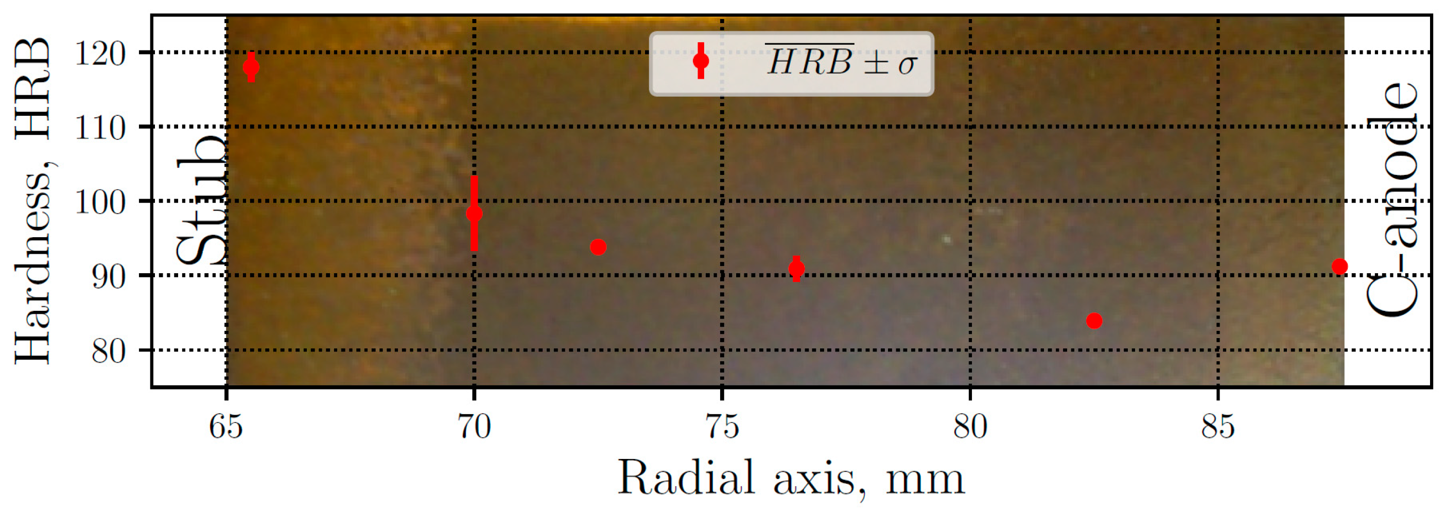
The thimble hardness measurements are presented in Figure 3, where the mean values are plotted along with their respective standard deviation, ranging between 84 and 118 HRB. The lower values correspond to the gray iron zone, while the highest values correspond to white iron. The latter are caused by the presence of iron carbides, particularly cementite (Fe3C), which is much harder and brittle than graphite. In the GWT zone, the hardness values have more dispersion due to the presence of both graphite and cementite. Away from the white zone, typical levels of gray iron appear, reaching the minimum value. Moreover, the zone closer to the carbon anode have a hardness of 91 HRB, where the cooling rate is quite high, but not enough to produce carbides. The background of Figure 3 shows a sample of the thimble after polished, where the white cast iron can clearly be seen (naked eye) at the left of the sample.
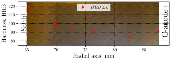
Figure 3.
Measured mean hardness () and standard deviation (σ) along radial axis. Macrograph of a polished sample of the thimble (background).
4.1.2. Stress-Strain Curve
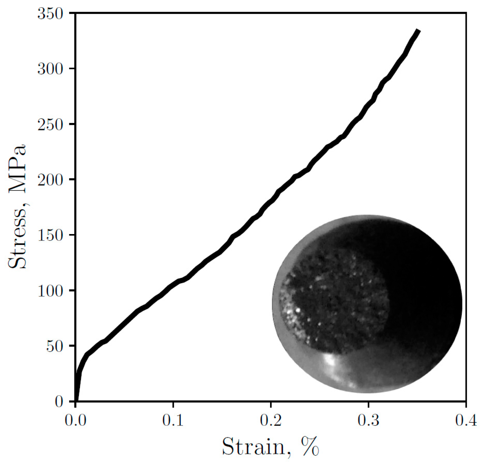
Some researchers have characterized and modeled the GCI elastoplastic behavior [30,51,52,53]. In this work, the stress-strain curve is experimentally measured and presented in Figure 4 along with an image of the fractured sample, which reveals the presence of white iron and its brittle fracture. The measured ultimate tensile strength is σf = 334.9 MPa, similar to the one reported in [30] for GCIs samples with higher cooling rates. Furthermore, the Young’s modulus calculated from Figure 4 is E = 82.6 GPa. Owing to the sample have a mixture of eutectics, a higher graphite content affects diminishing E [27] while at the same time white iron increases this value [54]. Nevertheless, Figure 4 shows the low percentage of white iron in the sample which consequently does not affect so much the material elastic response. On the other hand, this low percentage is able to affect the toughness through the presence of carbides that reduce ductility, thereby preventing the curve from having a distinctive yield point followed by plastic deformation, causing the brittle fracture during the elastic behavior.
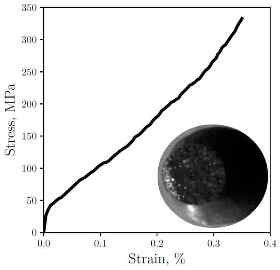
Figure 4.
Experimental engineering stress-strain curve for the thimble sample with an image of the tested sample.
4.1.3. Microstructure
The micrographs were obtained from different points along the radial axis of the sample in an as-cast state and etched in 3% Nital. Figure 5 shows the five representative microstructures observed from the inner part of the thimble to its outer part: (a) the white zone near to the stub (from 65 to 67.5 mm), (b) the white to gray transition (from 67.5 to 72 mm), (c) the gray zone next to the transition zone (from 72 to 75 mm), (d) the gray zone at center of the sample (from 75 to 84 mm), and (e) the gray zone near to the anode (from 84 to 87.5 mm). Note that the locations where the hardness was measured, see Figure 3, can be associated with the corresponding micrographs shown in Figure 5.

Figure 5.
Micrographs (200 times magnification) etched in 3% Nital along the radial axis from (a) inside to (e) outside of the thimble, at (a) 66; (b) 70; (c) 75; (d) 80 and (e) 85 mm from the axis. Scale bar is the same for the five figures, 100 μm.
The gray zone in Figure 5 shows flake graphite, promoted by the absence of nodularizing elements and the high Si content. Furthermore, short flakes caused by the high undercooling, typical of a type D graphite [55], can be seen where the dendrites are clearly formed due to this effect. On the other hand, white eutectic composed by cementite and austenite grows in ledeburite form promoted by Si instead of in plate type cementite [56].
Experimental results from [57] show that, for relatively high cooling rates, Si contents greater than 3.2% retard and avoid carbide formation. In spite of the higher Si content of 3.93% present in the GCI thimble (see Table 1), white iron appears at zones with higher cooling rates, i.e., near the stub connection, even in the absence of carbide-formers: Cr and V values can be considered negligible in this context (<0.04%) and, although Mn could also produce carbides, contents higher than 3.5% are needed.
Since the thimble is a highly hypereutectic material, with CE = 5.3, one could expect a considerable amount of primary graphite [58]. However, despite this, no primary graphite is formed since the rapid solidification does not allow the nucleation and growth of this proeutectic phase thus reducing the time available for such growth to take place [45].
4.2. Simulation
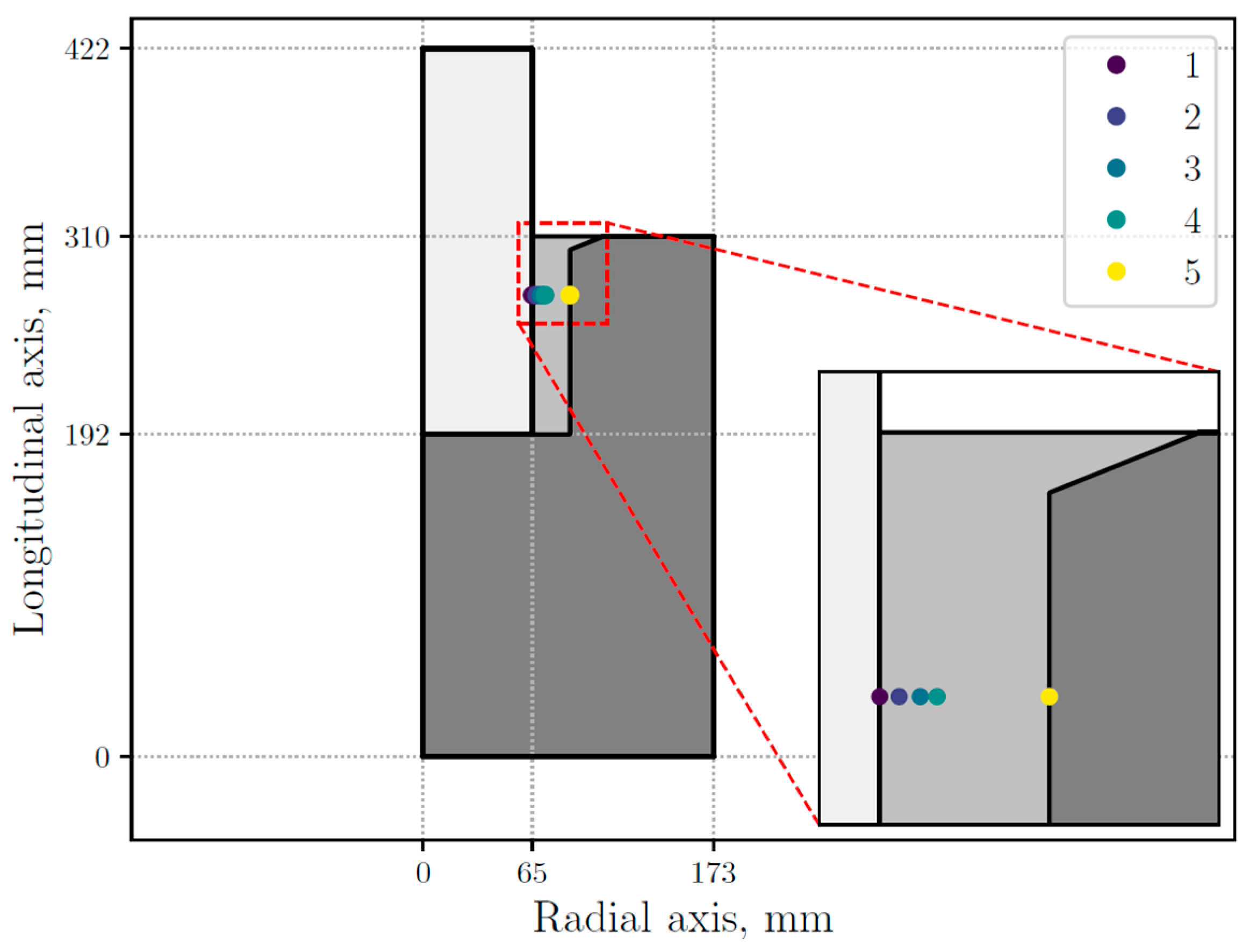
The numerical results show that the most significant microstructural changes occur along the radial, rather than longitudinal, axis. Therefore, as in the experimental measurements, the evolution of different variables of the model is presented along the radial axis of the thimble. Thus, the numerical results are presented at the points marked in Figure 6, selected in such way that they may capture microstructural transitions, specifically the GTW transition at both the inner and outer edges of the sample. The selected points are located at 65.05, 67.60, 70.39, 72.62, and 87.45 mm in the radial axis.
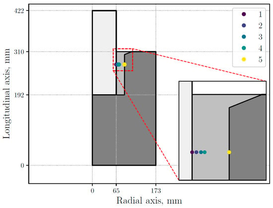
Figure 6.
STC (stub-to-carbon) assembly sectional view with five selected points inside the thimble.
4.2.1. Cooling Curves
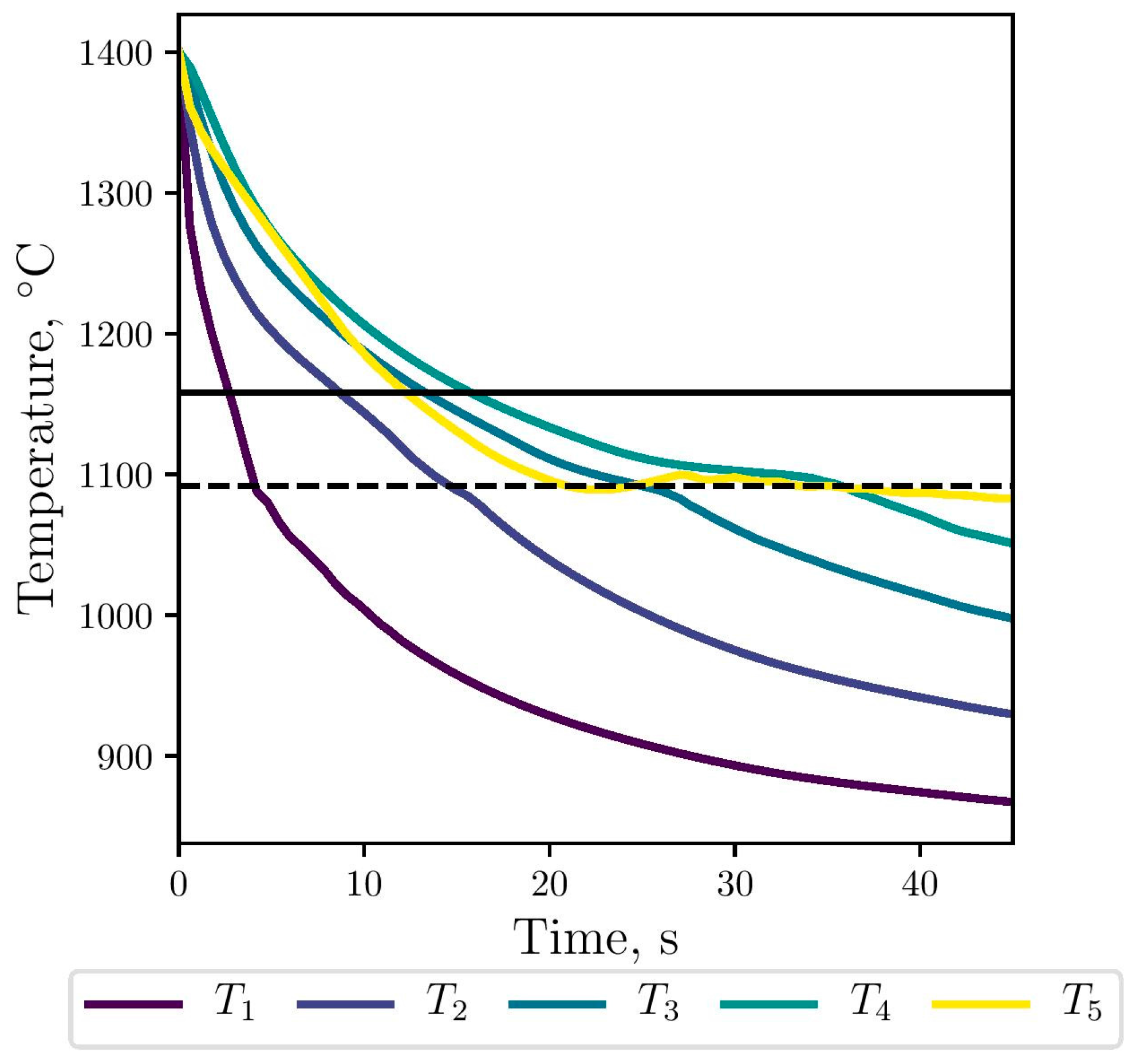
The gray eutectic crystallization, i.e., the stable transformation, begins at Tg, marked with the horizontal line in Figure 7. Then, below Tc, marked with the horizontal dashed line, the metastable transformation starts with the nucleation and growth of the white eutectic. At this temperature, both eutectics can growth in a competitive way. As expected, the simulated cooling rates along the thimble decrease as it moves away from the stub (selected points from 1 to 4). Near the carbon anode, the cooling curve in yellow is similar to that obtained in points 3 and 4 until Tc; below this temperature, the solidification process is slower. At the top of the thimble, the maximum calculated cooling rate is −43 °C/s, which is consistent with the value −40 °C/s reported in [2].
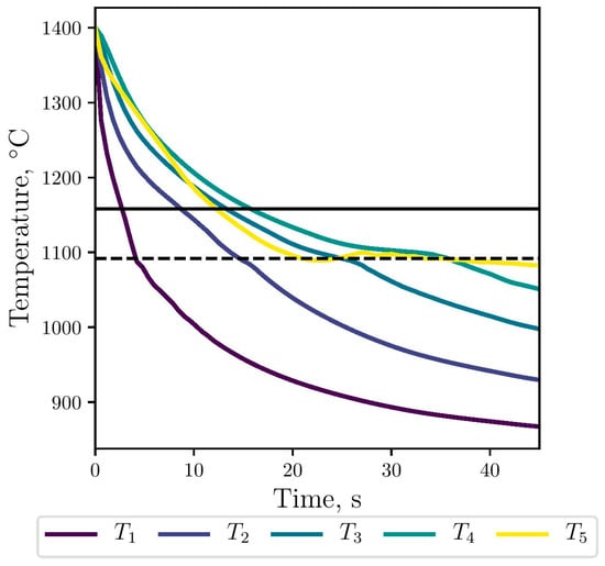
Figure 7.
Numerical cooling curves for the selected points at the thimble, against stable (black line) and metastable (dashed line) transformation temperatures.
4.2.2. Profile of Gray and White Fractions
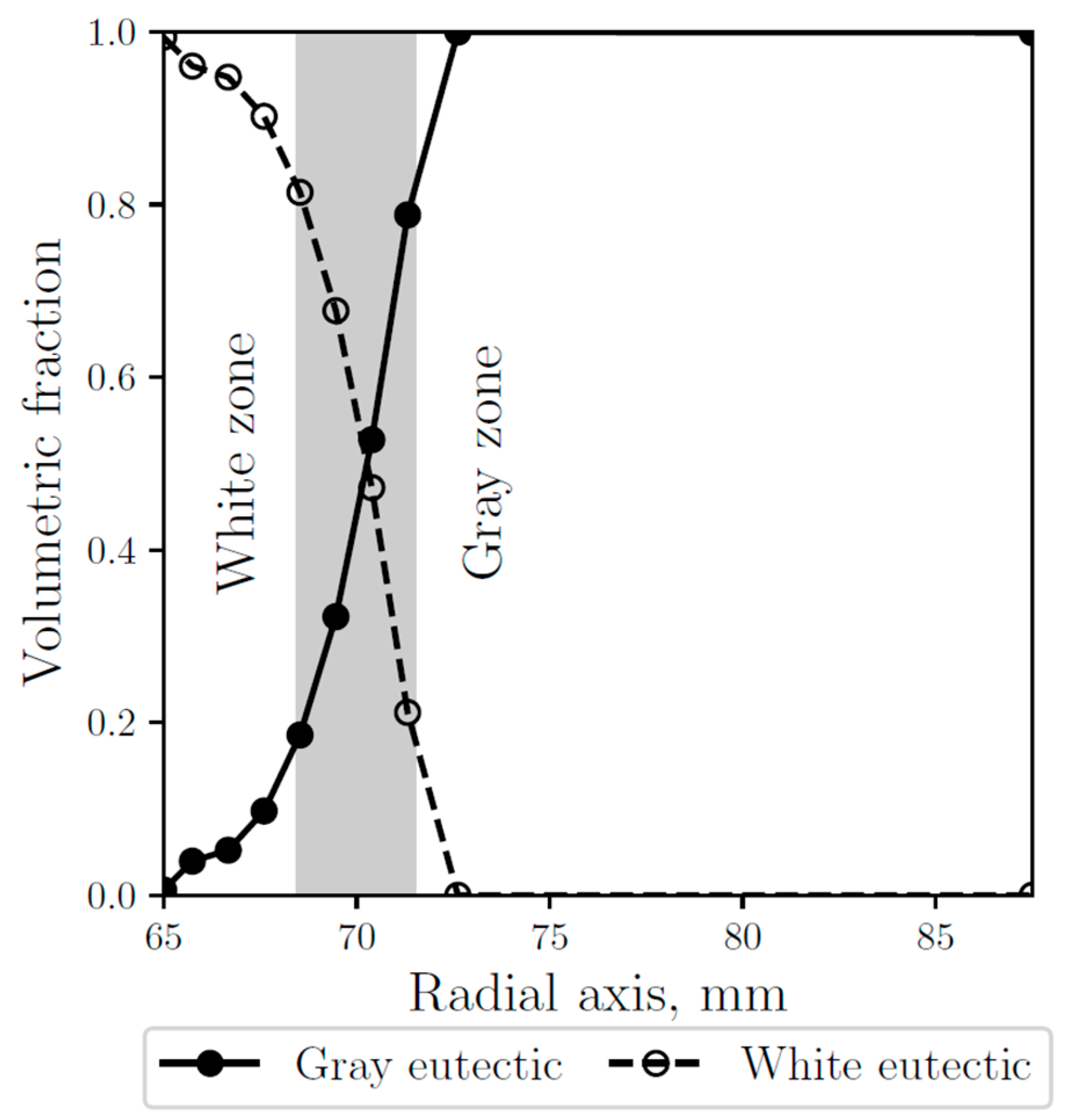
As shown in Figure 8, where the gray and white fraction along the radial axis are compared with the observed white and gray zones, the numerical results are validated, obtaining a good agreement, consistent with the microstructures observed at the micrographs (see Figure 5). The anode carbon has a relatively high thermal conductivity coefficient, however, the outside part of the thimble that is in contact with it did not form white eutectic in the simulations, which is consistent with the observations.
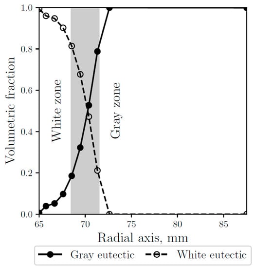
Figure 8.
Simulated gray (continuous line) and white (dashed line) eutectic fractions along the radial axis. The gray area represents the experimentally observed transition zone.
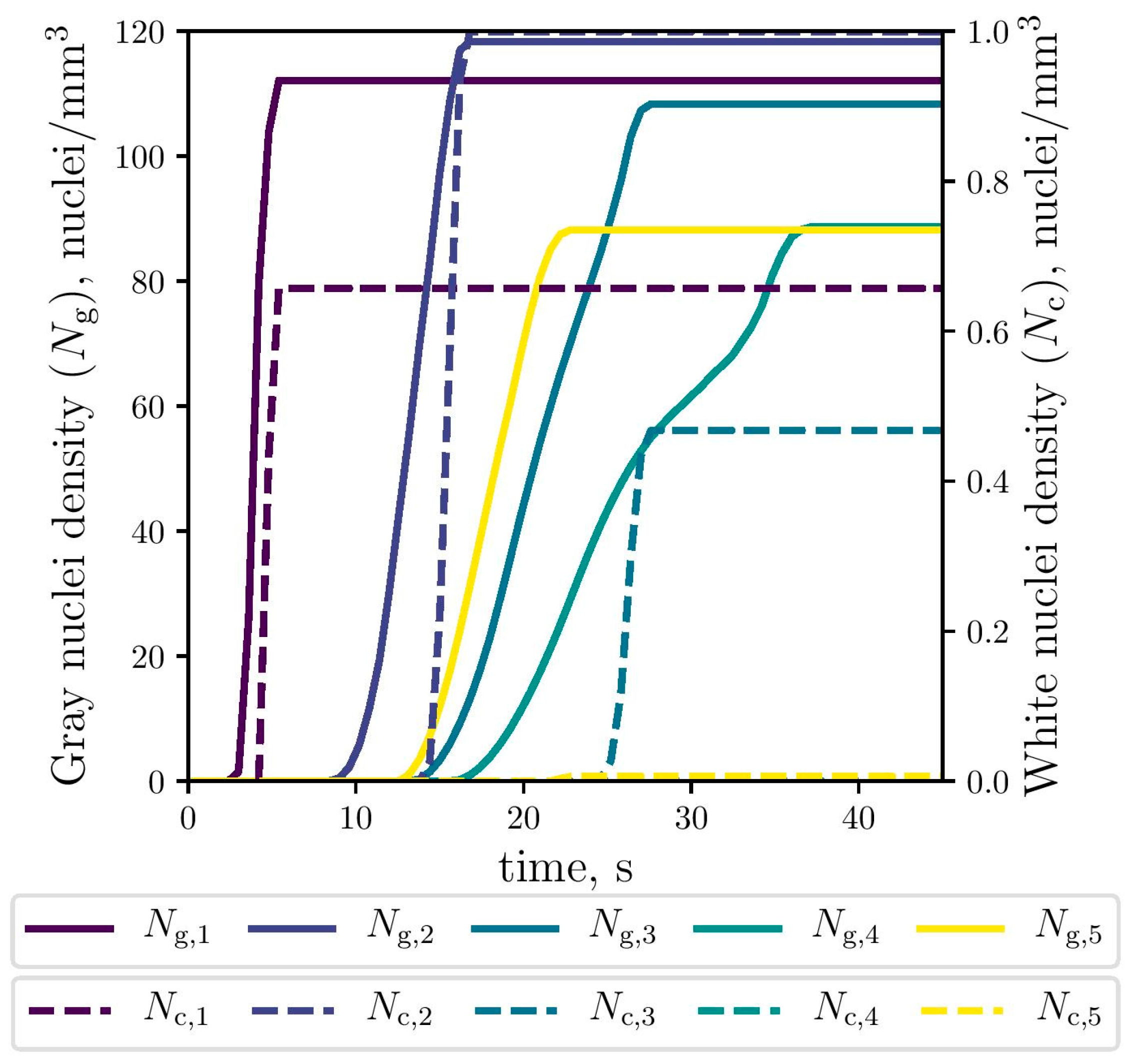
4.2.3. Evolution of Gray and White Fractions, Eutectic Radii and Densities
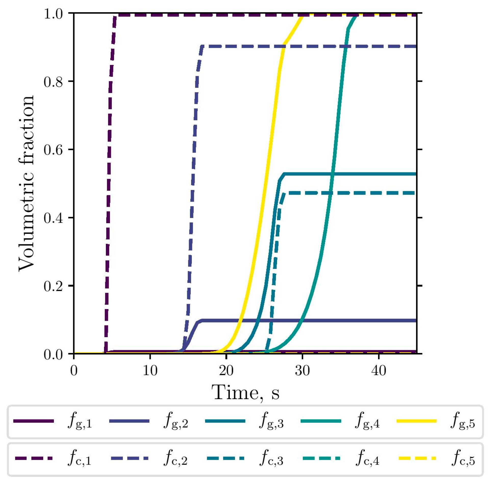
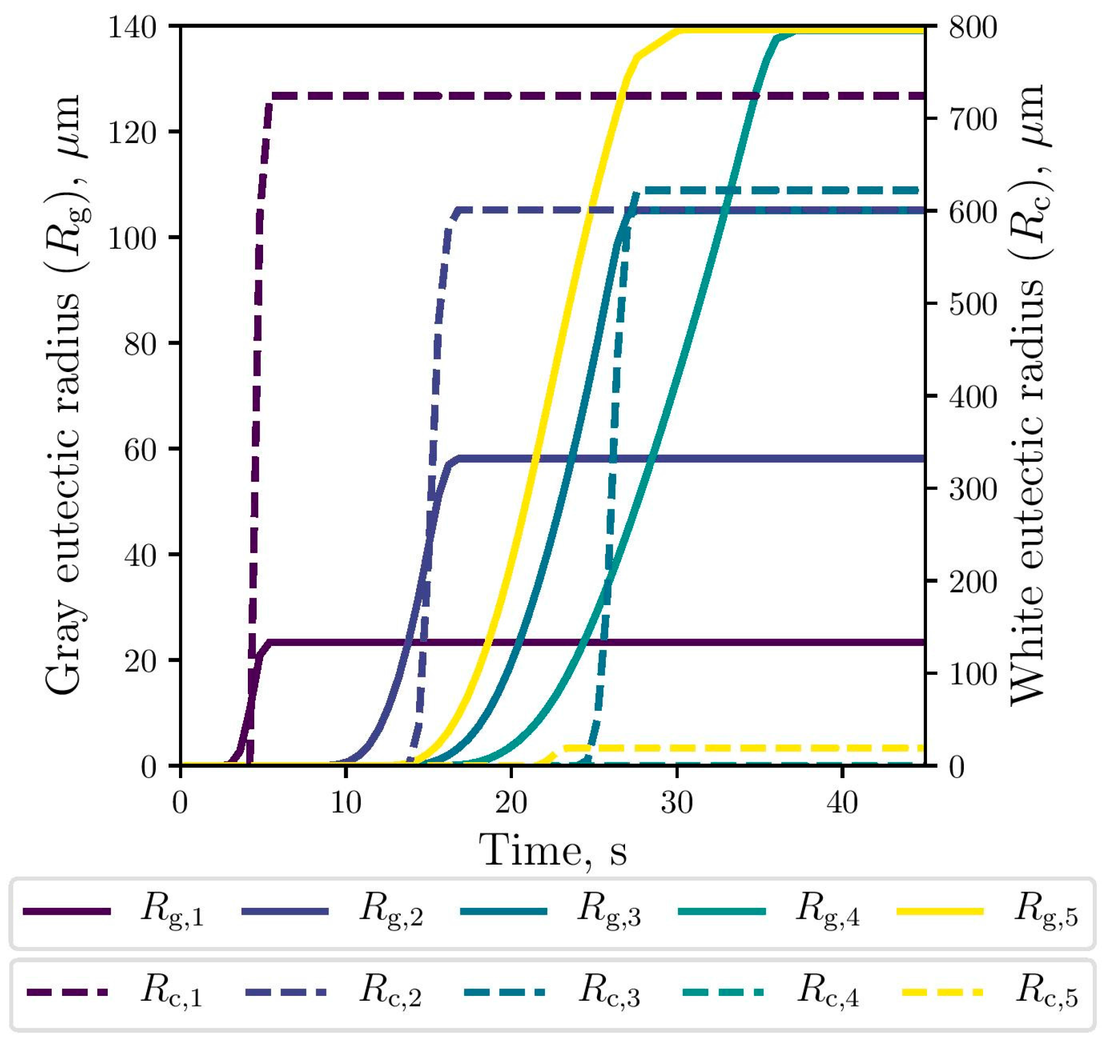
The simulated evolution of the microstructural variables is shown in Figure 9, Figure 10 and Figure 11. The competitive growth between the gray and white eutectics can be seen in Figure 9. Figure 10 shows that the growth of the white eutectic is much faster than the gray eutectic because the diffusion of atoms needed to form carbides (i.e., cementite) is much lower than that for graphite [56]. However, the white eutectic nucleation is rather sluggish [5] requiring lower temperatures to begin. Therefore, as shown in Figure 11, lesser quantities of white eutectic grains, but greater than the gray ones, are obtained. So, it is seen that growth rate plays an important role on the final volumetric fraction, since once the metastable solidification begins, the white fraction increases rapidly, as can be seen in Figure 9.
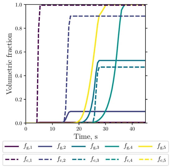
Figure 9.
Simulated gray (continuous lines) and white (dashed lines) eutectic evolution at the selected points.
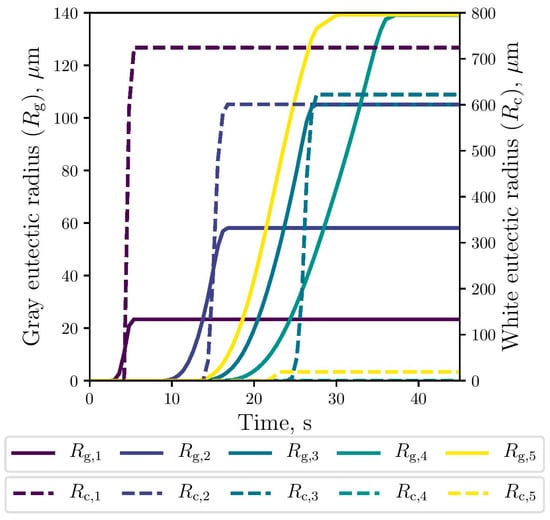
Figure 10.
Simulated gray (continuous lines) and white (dashed lines) eutectic radii evolution at the selected points.
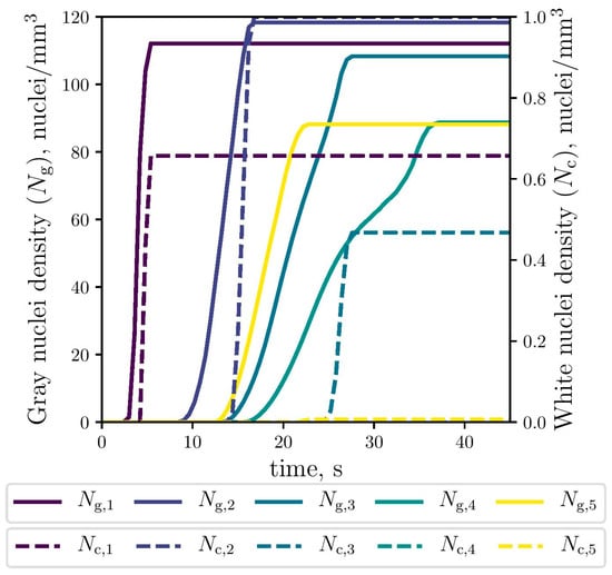
Figure 11.
Simulated gray (continuous lines) and white (dashed lines) eutectic nuclei evolution at the selected points (The dashed lines of Nc,4 and Nc,5 were lapped with each other).
4.3. Hardness Prediction
Numerical models proposed to predict hardness are formulated from empirical relationships, where most of them relate hardness with cooling rate (CR). Catalina et al. [35] summarized these models and developed one to predict hardness depending on microstructure properties, specifically, relating hardness with pearlite spacing. In the present work, hardness is predicted by considering both thermal and microstructural variables. Firstly, hardness is estimated using an empirical equation reported in [22] which relates hardness (H) with cooling rate (CR):
where a table conversion [59] was used to change the measured values from HRB to HB units, thus allowing the validation of the numerical results. Secondly, hardness is predicted from microstructural results. To this end, a correlation proposed in [60] to calculate the fracture strength using a Griffith fracture criterion is used:
where σf is the ultimate tensile strength, KIC is the fracture toughness, γ is the surface energy density, E is the Young´s modulus experimentally measured, and is the maximum graphite flake length calculated as 95% of the gray eutectic diameter [33]. Therefore, the hardness can be determined through the ultimate tensile strength by the following relation [34]:
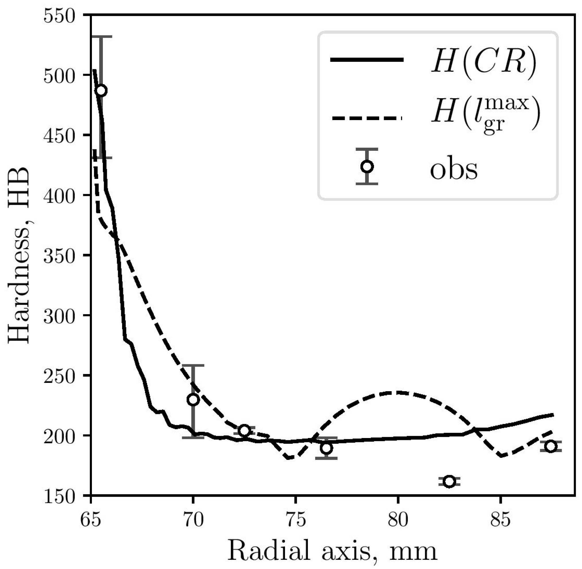
In Figure 12, predicted hardness results are plotted against the corresponding measured data. While the numerical results obtained by Equation (4) show good agreement with the experimental observations, the results obtained by Equation (7) show a significant difference for a part of the gray zone, at 15 mm from the center. From the micrographs shown in Figure 6, it can be seen that graphite flakes are larger at that zone (Figure 5d), which is also captured by the model, obtaining higher values for Rg(see Figure 10) and . Due to this increase in graphite flakes, the microstructural hardness model (Equation (7)) also increases the hardness values at this zone although, however, this is not consistent with the measured values.
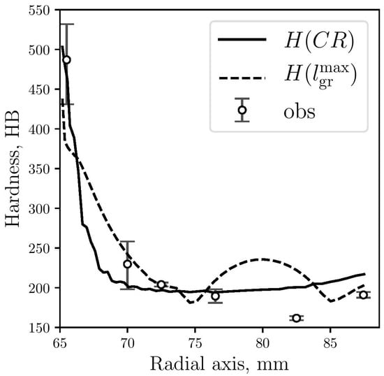
Figure 12.
Hardness predicted by Equation (4) (continuous line) and Equation (7) (dashed line) compared with measured data (circles).
5. Conclusions
An extension of a thermal microstructural model previously developed by the authors was developed to simulate the GWT, and was presented and used to simulate the rodding process of a STC assembly. Experimental and validated numerical results of the GWT during solidification of a hypereutectic GCI thimble have been presented. The following conclusions may be drawn from the present work:
- The measured hardness values and stress-strain curve were strongly affected by the observed microstructure.
- The computed GWT was consistent with the experimental data, thus validating the model prediction capabilities.
- Hardness was predicted via two methods that respectively consider cooling rates and microstructural parameters. When compared with the measured hardness values, predictions provided by the first method are in better agreement.
The use of this model as a reliable microstructure predicting tool in industrially relevant casting and heat treatment applications will be the subject of future research.
Acknowledgments
The authors are grateful for the financial support provided by CONICYT-REDES 150041.
Author Contributions
Alejandro Urrutia and Diego J. Celentano have done the experimental procedure and modeling, respectively. Both of them participated in numerical simulations, discussion of results and writing of the manuscript. Dayalan R. Gunasegaram was in charge of discussion of results and writing of the manuscript.
Conflicts of Interest
The authors declare no conflict of interest.
Abbreviations
| Table of Symbols | |
| ρ | Density |
| A | Nucleation parameter |
| B | Growth parameter |
| c | Specific heat |
| CE | Carbon equivalent |
| CR | Cooling rate |
| D | Diffusion coefficient |
| f | Volumetric fraction |
| fpt | Phase change function |
| H | Hardness |
| h | Effective heat transfer coefficient |
| k | Thermal conductivity |
| L | Latent heat |
| m | Growth exponent |
| N | Grain density |
| n | Nucleation exponent |
| R | Grain radius |
| T | Temperature |
| t | Time |
| Subscripts and Superscripts | |
| γ | Austenite |
| θ | Cementite |
| c | White eutectic |
| eut | Eutectic |
| g | Gray eutectic |
| gr | Graphite |
| l | Liquid |
| max | Maximum |
References
- Molenaar, D.; Ding, K.; Kapoor, A. Development of industrial benchmark finite element analysis model to study energy efficient electrical connections for primary aluminium smelters. In Proceedings of the TMS Light Metals, San Diego, CA, USA, 27 February–3 March 2011; pp. 985–990. [Google Scholar]
- Gunasegaram, D.R.; Molenaar, D. A Fully Coupled Thermal-Electrical-Mechanical Transient FEA Model for a 3D Anode Assembly. In Proceedings of the TMS Light Metals, San Antonio, TX, USA, 3–7 March 2013; pp. 1341–1346. [Google Scholar]
- Gunasegaram, D.R.; Molenaar, D. Towards improved energy efficiency in the electrical connections of Hall–Héroult cells through Finite Element Analysis (FEA) modeling. J. Clean. Prod. 2015, 93, 174–192. [Google Scholar] [CrossRef]
- Gunasegaram, D.R.; Molenaar, D. Rodding in Hall–Héroult Cells: An Fea Model that Predicts Room Temperature Mechanical Properties and Cracking Tendency of Thimbles. In Proceedings of the TMS Light Metals, San Diego, CA, USA, 16–20 February 2014; pp. 1287–1292. [Google Scholar]
- Fraś, E.; Górny, M.; López, H.F. The transition from gray to white cast iron during solidification: Part I. Theoretical background. Metall. Mater. Trans. A 2005, 36, 3075–3082. [Google Scholar] [CrossRef]
- Fraś, E.; Górny, M.; López, H.F. The Transition from gray to white cast iron during solidification: Part II. Experimental verification. Metall. Mater. Trans. A 2005, 36, 3083–3092. [Google Scholar] [CrossRef]
- Fraś, E.; Górny, M.; López, H.F. The transition from gray to white cast iron during solidification: Part III. Thermal analysis. Metall. Mater. Trans. A 2005, 36, 3093–3101. [Google Scholar] [CrossRef]
- Fraś, E.; Górny, M.; López, H.F. The effect of carbon on the transition from graphite to cementite eutectic in cast iron. Metall. Mater. Trans. A 2014, 45, 5601–5612. [Google Scholar] [CrossRef]
- Fraś, E.; López, H.F.; Kawalec, M.; Górny, M. Role of alloying additions in the solidification kinetics and resultant chilling tendency and chill of cast iron. Metals 2015, 5, 256–288. [Google Scholar] [CrossRef]
- Magnin, P.; Kurz, W. Competitive growth of stable and metastable Fe-C-X eutectics: Part I. experiments. Metall. Mater. Trans. A 1988, 19, 1955–1963. [Google Scholar] [CrossRef]
- Magnin, P.; Kurz, W. Competitive growth of stable and metastable Fe-C-X eutectics: Part II. Mechanisms. Metall. Mater. Trans. A 1988, 19, 1965–1971. [Google Scholar] [CrossRef]
- Maijer, D.; Cockcroft, S.L.; Patt, W. Mathematical modeling of microstructural development in hypoeutectic cast iron. Metall. Mater. Trans. A 1999, 30, 2147–2158. [Google Scholar] [CrossRef]
- Maijer, D.; Cockcroft, S.; Jacot, A. Modeling of microstructure and residual stress in cast iron calender rolls. Metall. Mater. Trans. A 2000, 31, 1201–1211. [Google Scholar] [CrossRef]
- Jacot, A.; Maijer, D.; Cockcroft, S.L. A two-dimensional model for the description of the columnar-to-equiaxed transition in competing gray and white iron eutectics and its application to calender rolls. Metall. Mater. Trans. A 2000, 31, 2059–2068. [Google Scholar] [CrossRef]
- Celentano, D.; Cruchaga, M. A thermally coupled flow formulation with microstructural evolution for hypoeutectic cast-iron solidification. Metall. Mater. Trans. B 1999, 30, 731–744. [Google Scholar] [CrossRef]
- Celentano, D.J.; Cruchaga, M.A.; Schulz, B.J. Thermal microstructural analysis of grey cast iron solidification: Simulation and experimental validation. Int. J. Cast Met. Res. 2005, 18, 237–247. [Google Scholar] [CrossRef]
- Urrutia, A.; Celentano, D.J.; Gunasegaram, D.R.; Deeva, N. Thermal microstructural multiscale simulation of solidification and eutectoid transformation of hypereutectic gray cast iron. Metall. Mater. Trans. A 2014, 45, 3954–3970. [Google Scholar] [CrossRef]
- Jelić, P.; Lazić, L.; Črnko, J. The effect of cooling rate on the properties of alloyed cast-iron sizing roll. Metalurgija 2010, 49, 45–48. [Google Scholar]
- Pluphrach, G. Study of the effect of solidification on graphite flakes microstructure and mechanical properties of an ASTM A-48 gray cast iron using steel molds. Sonklanakarin J. Sci. Technol. 2010, 32, 613–618. [Google Scholar]
- Samuelsson, D.P.B. Analysis of Microstructural Strain-Fields in Grey Cast Iron; Chalmers University of Technology: Göteborg, Sweden, 2011. [Google Scholar]
- Sahu, S.; Bhat, M.N.; Kumar, A.; Pratik, A.; Kumar, A. Effect of section thickness on the microstructure and hardness of gray cast iron (A simulation study). Int. J. Eng. Res. Technol. 2014, 3, 35–40. [Google Scholar]
- Jabbari Behnam, M.M.; Davami, P.; Varahram, N. Effect of cooling rate on microstructure and mechanical properties of gray cast iron. Mater. Sci. Eng. A 2010, 528, 583–588. [Google Scholar] [CrossRef]
- Wilberfors, F.; Svensson, I.L.; Elfsberg, J.; Richnau, K.; Ipek, N. Local chill as a mean of increasing strength in grey cast iron. Int. J. Cast Met. Res. 2016, 29, 40–46. [Google Scholar] [CrossRef]
- Stefanescu, D.M. Thermal analysis—Theory and applications in metalcasting. Int. J. Met. 2015, 9, 7–22. [Google Scholar] [CrossRef]
- Riposan, I.; Chisamera, M.; Stan, S.; Hartung, C.; White, D. Three-stage model for nucleation of graphite in grey cast iron. Mater. Sci. Technol. 2010, 26, 1439–1447. [Google Scholar] [CrossRef]
- Biswas, S.; Monroe, C.; Prucha, T. Use of published experimental results to validate approaches to gray and ductile iron mechanical properties prediction. Int. J. Met. 2017, 11, 656–674. [Google Scholar] [CrossRef]
- Collini, L.; Nicoletto, G.; Konečná, R. Microstructure and mechanical properties of pearlitic gray cast iron. Mater. Sci. Eng. A 2008, 488, 529–539. [Google Scholar] [CrossRef]
- Onsoien, M.I.; Skaland, T. Preconditioning of gray iron melts using ferrosilicon or silicon carbide. AFS Trans. 2001, 1, 1–12. [Google Scholar]
- Cooper, C.A.; Elliott, R.; Young, R.J. Investigation of elastic property relationships for flake and spheroidal cast irons using Raman spectroscopy. Acta Mater. 2002, 50, 4037–4046. [Google Scholar] [CrossRef]
- Seah, K.H.W.; Hemanth, J.; Sharma, S.C. Effect of the cooling rate on the dendrite arm spacing and the ultimate tensile strength of cast iron. J. Mater. Sci. 1998, 33, 23–28. [Google Scholar] [CrossRef]
- Hsu, C.-H.; Lee, S.-C.; Shy, Y.-H.; Chiou, W.-T. Relationship between dynamic and static toughness of flake and compacted graphite cast irons. Mater. Sci. Eng. A 2000, 282, 115–122. [Google Scholar] [CrossRef]
- Xu, W.; Ferry, M.; Wang, Y. Influence of alloying elements on as-cast microstructure and strength of gray iron. Mater. Sci. Eng. A 2005, 390, 326–333. [Google Scholar] [CrossRef]
- Goettsch, D.D.; Dantzig, J.A. Modeling microstructure development in gray cast irons. Metall. Mater. Trans. A 1994, 25, 1063–1079. [Google Scholar] [CrossRef]
- Yeh, C.-P.; Hwang, W.-S.; Lin, C.-H. Numerical simulation on hardness distribution for a FC250 gray cast iron brake disc casting and its experimental verification. Mater. Trans. 2009, 50, 2584–2592. [Google Scholar] [CrossRef]
- Catalina, A.; Guo, X.; Stefanescu, D.M.; Chuzhoy, L.; Pershing, M. Prediction of room temperature microstructure and mechanical properties in gray iron castings. AFS Trans. 2000, 108, 247–257. [Google Scholar]
- Sare, I.R. Abrasion resistance and fracture toughness of white cast irons. Met. Technol. 1979, 6, 412–419. [Google Scholar] [CrossRef]
- Berns, H. Comparison of wear resistant MMC and white cast iron. Wear 2003, 254, 47–54. [Google Scholar] [CrossRef]
- Wiengmoon, A.; Chairuangsri, T.; Brown, A.; Brydson, R.; Edmonds, D.V.; Pearce, J.T.H. Microstructural and crystallographical study of carbides in 30 wt.% Cr cast irons. Acta Mater. 2005, 53, 4143–4154. [Google Scholar] [CrossRef]
- Wu, X.; Xing, J.; Fu, H.; Zhi, X. Effect of titanium on the morphology of primary M7C3 carbides in hypereutectic high chromium white iron. Mater. Sci. Eng. A 2007, 457, 180–185. [Google Scholar] [CrossRef]
- Zhi, X.; Xing, J.; Fu, H.; Xiao, B. Effect of niobium on the as-cast microstructure of hypereutectic high chromium cast iron. Mater. Lett. 2008, 62, 857–860. [Google Scholar] [CrossRef]
- Daimaruya, M.; Kobayashi, H.; Fuad, K. Thermoelasto-plastic stresses and thermal distortions in a brake drum. J. Therm. Stress. 1997, 20, 345–361. [Google Scholar] [CrossRef]
- Stefanescu, D.M.; Katz, S. Thermodynamic properties of iron-base alloys. ASM Handb. 2008, 15, 41–55. [Google Scholar]
- Heine, R.W. The Fe-C-Si solidification diagram for cast irons. AFS Trans. 1986, 94, 391–402. [Google Scholar]
- Stefanescu, D.M.; Alonso, G.; Larrañaga, P.; Suarez, R. On the stable eutectic solidification of iron-carbon-silicon alloys. Acta Mater. 2016, 103, 103–114. [Google Scholar] [CrossRef]
- Johnson, W.C.; Smartt, H.B. The role of interphase boundary adsorption in the formation of spheroidal graphite in cast iron. Metall. Mater. Trans. A 1977, 8, 553–565. [Google Scholar] [CrossRef]
- Abaqus 6.13. Available online: http://dsk.ippt.pan.pl/docs/abaqus/v6.13/ (accessed on 18 September 2013).
- MatWeb: Online Materials Information Resource. Available online: http://www.matweb.com/search/datasheetText.aspx?bassnum=M1020A (accessed on 1 March 2017).
- Andersen, D.H.; Zhang, Z.L. Fracture and physical properties of carbon anodes for the aluminum reduction cell. Eng. Fract. Mech. 2011, 78, 2998–3016. [Google Scholar] [CrossRef]
- Celentano, D.J.; Cruchaga, M.A.; Schulz, B.J. On the effect of natural convection on the thermal-microstructural evolution in gray cast-iron solidification. Metall. Mater. Trans. B 2006, 37, 253–264. [Google Scholar] [CrossRef]
- Nastac, L.; Stefanescu, D.M. Prediction of the gray-to-white transition in cast iron through solidification modeling. AFS Trans. 1995, 103, 329–337. [Google Scholar]
- Josefson, B.L.; Hjelm, H.E. Modelling Elastoplastic Deformations in Grey Cast Iron. In Low Cycle Fatigue and Elasto-Plastic Behaviour of Materials—3; Rie, K.T., Grünling, H.W., König, G., Neumann, P., Nowack, H., Schwalbe, K.-H., Seeger, T., Eds.; Springer: Dordrecht, The Netherlands, 1992; pp. 465–472. [Google Scholar]
- Altenbach, H.; Stoychev, G.B.; Tushtev, K.N. On elastoplastic deformation of grey cast iron. Int. J. Plast. 2001, 17, 719–736. [Google Scholar] [CrossRef]
- Stoychev, G. FE analysis of gray cast iron structural elements. Mach. Des. 2010, 2, 335–340. [Google Scholar]
- Angus, H.T. Cast Iron: Physical and Engineering Properties; Elsevier: Amsterdam, The Netherlands, 2013. [Google Scholar]
- Elkem Foundry. Available online: http://www.elkemfoundry.com.cn/pdf/GraphiteStructuresInCI.pdf (accessed on 11 January 2017).
- Jiyang, Z. Color metallography of cast iron. China Foundry 2011, 8, 447–462. [Google Scholar]
- Khalil-Allafi, J.; Amin-Ahmadi, B. Effect of mold hardness on microstructure and contraction porosity in ductile cast iron. J. Iron Steel Res. Int. 2011, 18, 4447–4467. [Google Scholar] [CrossRef]
- Hillert, M. Comments on ‘‘Eutectic solidification of gray cast iron’’. Scr. Mater. 2005, 52, 249–250. [Google Scholar] [CrossRef]
- Kelly Pipe. Available online: http://www.kellypipe.com/assets/files/hardcon.pdf (accessed on 12 April 2017).
- Bates, C. Alloy element effect on lamellar iron properties: Part II. AFS Trans. 1986, 94, 889–905. [Google Scholar]
© 2017 by the authors. Licensee MDPI, Basel, Switzerland. This article is an open access article distributed under the terms and conditions of the Creative Commons Attribution (CC BY) license (http://creativecommons.org/licenses/by/4.0/).

