Abstract
Oxide films or inclusions can reduce the continuity and integrity of materials and they always lead to a significant reduction in the mechanical properties of an aluminum alloy. They can greatly reduce the plastic flow behavior of materials, thus affecting the subsequent processing performance. Therefore, an effective ultrasonic assisted preparation technology has been applied to industrial manufacturing of large-scale aluminum alloy ingots (with diameter: Φ = 1250 mm and height: h = 3750 mm). However, the mechanisms of ultrasonic purification on the large-scale ingots are not clear. Therefore, a number of aluminum alloy casting experiments were carried out to produce a conventional hot top semi-continuous ingot (CHTI) and an ultrasonic hot top semi-continuous ingot (UHTI) in this work. The microstructures of CHTI and UHTI were analyzed by optical microscopy (OM) and scanning electron microscopy (SEM). The results indicated that there were some oxide film defects in the CHTI but some finely dispersed inclusion particles were discovered in the UHTI. The X-ray diffraction (XRD) data showed that the component of inclusion was Al2O3. According to the different cavitation effects of the different areas of the molten aluminum, the process of ultrasonic purification was divided into three periods and the mechanisms in each period were separately studied.
1. Introduction
The 2219 Al alloy has been used for manufacturing various aerospace components (i.e., oxidizer and fuel tanks) attributable to its high strength, high fracture toughness, and reliable weldability [1,2]. The quality and performance of the large-sized ingots are very important in the realization of performance (high strength, lightweight, stress-corrosion resistance, and stability) and the technical target in large-scale aerospace components [3]. However, owing to the large size (with a diameter of over 600 mm), many defects are easy to generate such as segregation, shrinkage, porosity, inclusions, and cracks, and are harmful to the mechanical properties of the ingot, such as strength, hardness, and elongation rate [4]. Therefore, it is urgently necessary to produce high-performance large-sized aluminum ingots to manufacture high-performance components that can adapt to complex working conditions.
In recent years different advanced methods, like microwave energy [5,6,7], electromagnetic technology [8], and ultrasonic technology [9,10,11] were employed as material processing techniques for the processing of materials including aluminum alloy. Ultrasonic assisted manufacturing technology has been studied for decades in metal manufacture. Many scholars like Eskin [9,10], Li [11], and Abramov [12,13] have studied the mechanisms of ultrasonic treatment on a liquid alloy. Wang [14] used a novel experimental approach to investigate the effect of ultrasonic on the fragmentation of primary crystals and found a slow effect via a fatigue-type failure. Jaoude [15] proved that a significant grain refinement of a DC-cast 6082 commercial alloy could be achieved by applying an ultrasonic melt treatment prior to casting on a Zr containing 6082 alloy without any commercial grain refiner addition. Li and Li [16] placed three ultrasonic devices in the large-sized aluminum ingots casting process for the first time and found that the acoustic streaming effect was not hindered so that it could reach the whole large-scale melt and led to the enhancement of the homogeneous distribution of the solute. However, the ultrasonic purification on the large-scale solidification of 2219 aluminum has not studied in detail.
The liquid aluminum surface is easy to oxidize during the melting, transferring, and pouring operations, which may entrain oxide films into the casting [17,18]. The oxide films or inclusions can reduce the continuity and integrity of the material and they always lead to a significant reduction in the mechanical properties of the aluminum alloy. They can greatly reduce the plastic flow behavior of materials, thus, affecting the subsequent processing performance [19,20]. As we all know, ultrasonic has a cleaning function but the research on ultrasonic purification has been limited to the exploration of ultrasonic processing parameters in recent years. Shao [21] carried out an experiment on the effect of ultrasonic power on grain refinement and obtained an ultrasonic power parameter, which had a better purification. Zhang [22] also explored the relationship between ultrasonic purification and ultrasonic parameters (i.e., ultrasonic power, treatment time, and melt temperature). However, neither of them studied the mechanisms of ultrasonic purification on an alloy. However, the existence of oxide films or inclusions has always been a potential safety hazard for ingots. No literature can clearly explain the mechanisms of ultrasonic purification on inclusions.
In this paper, the mechanisms of ultrasonic cavitation on oxide inclusions in large-sized 2219 aluminum alloy ingots (Φ = 1250 mm and h = 3750 mm) were investigated for the first time. The cavitation effect can accelerate the melt flow and promote the collision and breakage of the oxide film and inclusions in the melt. Meanwhile, the high-temperature, high-pressure, and micro-jet generated by the cavitation bubbles collapsing can effectively break the mixed particles. Therefore, the cavitation effect plays a key role in cleaning inclusions. The research in this paper will contribute to the further study of ultrasonic purification theory and technology. In addition, this research will provide some experimental and theoretical basis for the industrial application of ultrasonic-assisted manufacturing technology.
2. Materials and Methods
The main research material of this experiment was 2219 aluminum alloy and its main chemical compositions are shown in Table 1. Firstly, a series of aluminum alloy casting experiments were carried out to produce a conventional hot top semi-continuous ingot (CHTI) and an ultrasonic hot top semi-continuous ingot (UHTI). The ultrasound-assisted casting system is shown in Figure 1. The key parameters of the casting process are listed in Table 2.

Table 1.
The chemical compositions of the 2219 Al alloy (wt. %).
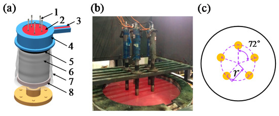
Figure 1.
(a) Schematic illustration of the ultrasound-assisted direct-chill casting system for manufacturing large-scale Al alloy ingots, including 1. ultrasonic generators, 2. molten aluminum, 3. launder, 4. hot-top, 5. crystallizer, 6. ingot, 7. cooling water, 8. pulling device; (b) the industry-level casting apparatus for large-scale Al alloy casting. The five ultrasonic generators were symmetrically placed in (c), the value of radius (r) was 300 mm.
Table 2.
Parameters used for the large-scale Al alloy casting.
Secondly, after homogeneous treatment at 475 °C for 72 h, without protective gas, in an electric resistance furnace (20 ton aluminum alloy round ingot heating furnace by Suzhou Longray Thermal Technology Co., Ltd., Suzhou, China), two cylindrical cross-sections with a thickness of 20 mm were selected for microstructural characterization. These two cross-sections were transversely cut from the top and bottom positions of CHTIs and UHTIs. The samples of Φ20 mm × 20 mm were then chosen at specific positions along the radial direction of each cross-section, as shown in Figure 2. After the samples were mechanically ground, polished, and etched in a solution of 100 g/L sodium hydrate (NaOH) for 1.5 min, they were washed in s solution of 15% nitric acid (HNO3), and then absolute ethyl alcohol and finally dried in a dryer. Afterwards they were examined using an optical microscope (OM) (DSX50240 by OLYMPUS (China) Investment Co., Ltd., Beijing, China), which was equipped with image analysis software OLYCIA DSX (DSX50240 by OLYMPUS (China) Investment Co., Ltd., Beijing, China) to analyze the particle size, numbers of per unit area (NPA), and the area fraction of the suspected inclusion defects. The samples were then characterized by X-ray diffraction (XRD) (D8 discover by Bruker AXS, Karlsruhe, Germany) for component identification.
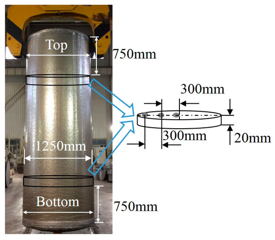
Figure 2.
The manufactured large-scale cylindrical 2219 Al alloy ingot and the schematic diagram of the sampling method.
Two samples of 50 mm × 50 mm × 150 mm were cut from a position of 300 mm away from the center in the bottom pieces of CHTI and UHTI. They were heated to 480 °C for 12 h, without protective gas in an electric resistance furnace (a 1 ton aluminum alloy round ingot heating furnace by Suzhou Longray Thermal Technology Co., Ltd., Suzhou, China), and then they were compressed on the forging machine (4000 ton forging machine by Ding Neng Machinery Manufacturing Co., Ltd., Wenzhou, China) from 150 mm to 30 mm. The compressed samples were cut into two pieces separately along the diameter direction. A groove with a depth of 1/3 in the sample’s width was produced on the cross-section. Then, the samples were heated to 480 °C for 0.5 h and quenched with water. Finally, the samples were broken off the forging machine. The fractured samples were used to detect the presence of oxide films by SEM (Phenom ProX by Phenom Scientific Instrument Co., Ltd., Shanghai, China), which was equipped with energy dispersive X-ray spectroscopy (EDS, Phenom Scientific Instrument Co., Ltd., Shanghai, China).
Finally, fracture samples with the dimensions shown in Figure 3 were cut from the cross-sections in the top position 300 mm away from the center of the ingots for the test of the mechanical properties. Specifically, three samples from CHTI and three samples from UHTI were chosen to obtain average values of the mechanical properties. The samples were ground to obtain a smooth surface and to reduce the stress concentration. Then, the tensile tests were performed along the height direction using a CSS-44100 electronic universal testing machine (Changchun Test Machine Research Institute, Changchun, China) at room temperature with a loading rate of 2 mm/min. The tensile strength, yield strength, and elongation values of the samples were averaged. In order to obtain more detailed information on fracture morphology and composition, these samples were further observed using SEM. All the tests were completed in the National Key Laboratory of High-Performance Complex Manufacturing in Central South University, Changsha, China.
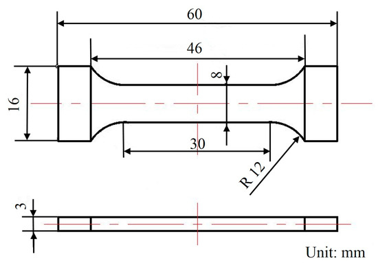
Figure 3.
The dimensions of the tensile sample.
3. Results
3.1. Microstructure
The grain structure of the CHTI is coarse columnar crystals and the secondary dendrite arm was obvious, as shown in Figure 4a–c. The average grain size was calculated (5% standard deviation) by the linear intercept method using five micrographs (10 intercepts) for each sample. The vertical red lines in Figure 4a,d are the measuring lines for calculating the grain size, and the inspection method refers to GB/T 3246.1-2012: Inspection method for the structure of wrought aluminum and aluminum alloy products-Part 1: Inspection method for microstructure [24]. The average grain size of the columnar crystals in CHTI increased from 300 μm at the edge to 530 μm in the center, while the edge and R/2 of the UHTI were equiaxed columnar crystals and the average grain diameter increased from 220 μm at the edge to 380 μm in the center. It can be seen from the diagram that ultrasonic treatment can obviously refine the grain and change the microstructure from the coarse columnar crystal to the uniform fine equiaxed crystal. The average grain size of the whole ingot section can be refined by the ultrasonic method and the grain refinement rates were 28% (in the center) and 27% (at the edge), respectively. The average grain size deviation in the ingot section was reduced from 230 μm of CHTI to 160 μm of UHTI, which resulted in the improvement of the uniformity of the ingot.
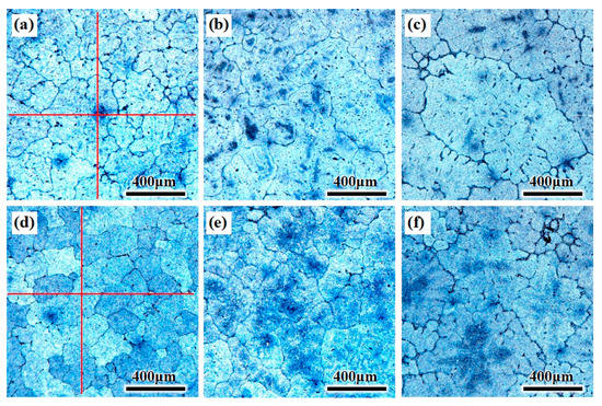
Figure 4.
OM microstructure of different parts of the two ingots. (a–c) edge, ½ radius, center of CHTI; (d–f) edge, ½ radius, center of UHTI.
3.2. Size, NPA, and Area Fraction Distribution of Suspected Inclusion
Inclusions, pores and inter-metallics simultaneously exist in the metallographic pictures but they can be distinguished by adjusting focal length and identifying colors. The size, NPA, and area fraction of the suspected inclusions in CHTI and UHTI samples were mounted using the commercial OLYCIA DSX software; the results are illustrated in Figure 5. The average size of the suspected inclusions (Figure 5a) in CHTI (10.61 μm) was larger than that in UHTI (8.10 μm). As a whole, the particle size of CHTI sharply increased to 15.50 μm in the area which was 100 mm away from the center. However, it did not have this tendency in UHTI and the suspected inclusions were only 9.32 μm. Additionally, inclusion defects above 10 μm did not exist in UHTI. The area fraction (Figure 5c) decreased by 21.22%, from 0.38% in CHTI to 0.30% in UHTI. However, the average number per square millimeter of suspected inclusion defects (Figure 4b) in CHTI was 6.13, while it was 9.47 in UHTI.
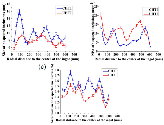
Figure 5.
The statistical contrast maps of the suspected inclusion defects between CHTI and UHTI. The diagrams of (a–c) are, respectively, the size, NPA, and area fraction distribution.
It was evident that the area fraction and NPA of suspected inclusion defects were smaller in the position 300 mm away from the ingot center, showing a tendency to rapidly increase and reaching maximum values along the radial distance. It has a key role in reducing the inclusions when the ultrasonic generators were placed 300 mm away from the center. This is because solidification began with the edge of ingot; the defect particles were imprisoned in the ingot and were unable to reach to the edge before freezing. Accordingly, the values of size, NPA, and area fraction were the smallest at the edge.
3.3. Mechanical Properties
The tensile properties (ultimate tensile strength (UTS), yield strength (YS), and elongation (%)) of CHTI and UHTI samples are given in Figure 6. The UTS, YS, and elongation values of CHTI increased; the UTS increased from 147 to 157 MPa (an increase of 6.6%), YS increased from 59 to 63 MPa (an increase of 7.3%), and elongation increased from 8.9% to 10.3% (an increase of 15.5%) at room temperature.
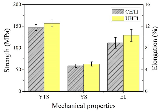
Figure 6.
Tensile properties of CHTI and UHTI samples.
3.4. SEM Morphology Characteristics and EDS Composition Analysis
Figure 7 shows the oxide films, which were found in the fractured compressed sample 300 mm away from the ingot center. The fracture morphologies of CHTI clearly exhibited as gray- or black-layered microstructures (Figure 7a) that were entirely different from nearby areas of the Al matrix. The size of the layered defect was approximately 500–800 μm. Different microstructures encountered in the aluminum castings could be distinguished through the comparisons of oxygen, copper, and aluminum peaks from EDS microanalysis spectra, as shown in Figure 6b–d. The result in Figure 6d indicates that the aluminum matrix did not contain oxygen, while the oxygen contents in the layered defect were much higher (Figure 7b,c). Combined with its morphological characteristics, the defect was considered to be an Al2O3 film. The oxide films in the ingot became dense during the hot compression process and hindered the plastic flow behavior of the deformed structure due to its hard material quality. In addition, the oxide film acted like a crack source in the material, which often caused stress concentration during the compression or tension tests. Therefore, the hot compression samples ultimately broke off at the position of the oxide film in this experiment.
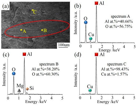
Figure 7.
(a) The gray-layered microstructure in SEM morphology of CHTI; (b–d) EDS microanalysis spectra from defects and matrix, respectively.
Figure 8a,b displays the SEM micrograph of the sample 300 mm away from the UHTI center. The fracture shows the characteristics of an intergranular fracture, tearing edges, and dimples in different sizes. The mechanisms of the dimples are the nucleation, growth, aggregation, and fracture of the cavities. Dislocation loops are stacked around the second phase particles or inclusions and maintained a balance when there was no external stress. Once the applied stress was large enough, these plugged dislocations become active, which caused the dislocation loop to move toward the second phase particles or inclusions. Cavities were formed when the accumulated elastic strain energy exceeded the interface bonding strength between the second phase particles or inclusions and the aluminum matrix [25,26]. We also found small irregular particles near the cavity in the fracture surface. Figure 8c,d shows the results of the EDS analysis for the particle and aluminum matrix. The matrix did not contain oxygen (Figure 8d), so they were judged as a type of Al-Cu secondary phase particles mixed with aluminum matrix. The heterogeneous-form particles (Figure 8b) had higher oxygen content and it was suspected to be a kind of oxide particle.
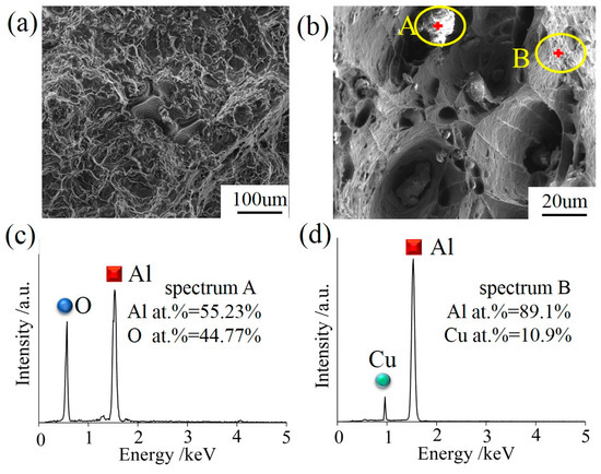
Figure 8.
(a) SEM morphology of the fracture microstructure in UHTI; (b) particle morphology and location sketch of EDS testing of fracture; (c,d) the EDS analysis of irregular particles and aluminum matrix.
3.5. XRD Analysis
The XRD analyses of 2219 UHTI are shown in Figure 9. The sample was 300 mm away from the center. From these pictures, we can see that there were two primary phases in the 2219 aluminum alloy, which were the α-Al phase and the θ (Al2Cu) phase [27]. There was also a peak of Al2O3 in the XRD graph and it appeared at an angle of 26.5° in the map. This indicates that there were oxide inclusions which chemical composition is Al2O3 in the sample.
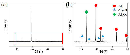
Figure 9.
(a) XRD analysis of UHTI; (b) partially enlarged picture of the XRD graph.
4. Discussion
The oxide films on the surface of liquid aluminum alloys were entrapped in the ingot as a consequence of either surface turbulence or surface tension [20]. The oxide films form stable solid inclusions in the process of solidification, which are highly damaging to aluminum alloy because of their nature as cracks. The thinnest oxide film observed by SEM was approximately 20 nm [21]. However, the oxide film formed during sample preparation or during the mechanical test at room temperature in the air was extremely thin; it only had 1–2 atomic layer thickness. Thus, it was almost undetectable in SEM and EDS, or invisible in any case. So it can be concluded that the Al2O3 film or particles observed in the ingot fracture microstructure were formed during the casting process, as shown in Figure 7a and Figure 8b.
The cavitation in the melt gradually attenuated from the central strong cavitation region (CSCR) to the edge of the ingot. It was speculated that the cavitation effect played three different roles in the purification of oxide films or inclusions. The first mechanism was the crush and erosion caused by the collapse of cavitation bubbles in a passing cavitation cloud in CSCR. The second one was a slow crushing period in the non-strong cavitation region (NSCR). Lastly, the third mechanism was a decline process with the fragmented inclusions rising away from the melt attached with the cavitation bubbles and the heterogeneous nucleation process, which is presented in Figure 10.
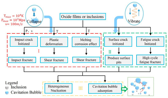
Figure 10.
Mechanisms of ultrasonic cavitation on oxide inclusions.
4.1. Fast Crushing Period
Owing to the continuous ultrasonic energy generated by the ultrasonic waves, the active cavitation bubbles in CSCR would repeat the process of growing, expanding, compressing, and collapsing, inducing the high-pressure micro-jet flow [28]. The speed of the micro-jet was calculated using the following formula [29].
where is bursting velocity of cavitation bubble (m/s), is external pressure of cavitation bubble (Pa), is internal pressure (Pa), is the alloy density (kg/m3), is maximum radius of cavitation bubble (m), is dynamic radius of cavitation bubble (m), and is specific heat capacity of steam (J/kg·K). Eskin stated that the asymmetric implosion of a bubble would expel a jet with a speed of roughly 100 m/s [10]. Such high-speed micro-jet has great potential to instantly promote rapid monotonic crack growth and fast fracture in the oxide films because an oxide film has a high elastic modulus and a poor capability for resisting micro-jet impact loading [30].
In addition to the fragmentation by a pulsating bubble via the mechanism of monotonic crack, another mechanism of fragmentation of oxide films by the flowing bubble cloud was also conjectured. The bubble cloud may represent a cluster of small bubbles that can travel or transport cavitation bubbles across the longitudinal direction of the waves where they can collapse, rebound, and multiply, as well as emit micro-jets and powerful shockwaves during the process [14]. It was potentially the formation of the bubble cloud that accelerated the impact on the melt, especially the inclusion, which would be beneficial to break the oxide film.
Rayleigh [31] found that when the cavitation bubble was closed from the radius to , the instantaneous pressure generated in the distance r = 1.587 R from the center was the largest. This pressure can be expressed as:
Feng [32] found that, by calculating the Rayleigh equation, the instantaneous pressure generated in the case of the collapse of the cavitation bubble was 1000 MPa. Similarly to the high-velocity micro-jet, this high pressure would potentially impact the surface of the oxidized inclusion and instantaneously crush the inclusions. Simultaneously, the pressure might force the micro-cracks in a slow crushing period to rapidly extend and fracture.
In the study of the cavitation erosion mechanism by ultrasonic treatment in the aluminum melt, Komarov [33] and Dong [34] indicated that ultrasonic cavitation could destroy the sample surface in a very short time and cause an increase in the surface roughness. Moreover, Dong conducted further research on the erosion mechanism of Ti alloy rods in an Al-alloy and found a phenomenon of suspected plastic deformation of the sample at the node position between the two strong cavitation regions. Based on this, it could be boldly speculated (though there were no reliable data to verify this conjecture) that the oxide films could also be corroded under ultrasonic cavitation, leading to plastic deformation. Micro-bubbles presented in Al alloy could be forced to oscillate in response to the alternating pressure waves of ultrasonic treatment. Such oscillations could generate shear forces and enhance fluid flow that could be applied in the inclusion fragmentation processes. Yusof, N.S. [35] also found that the high pressure generated by the collapsing bubble was a direct inducement to the shear generation. The shear fracture may be the most common mode of fracture for plastically deformed inclusions or oxide films. They were subjected to shear deformation by transverse shear, but it would break into tiny particles if the shear force was large enough or the cumulative shear deformation reached to the critical value.
According to the gas adiabatic equation: TV = Const. The highest temperature of the cavitation effect during the collapse of the cavitation bubble can be calculated as follows [20]:
where is the temperature of aluminum melt (K). It was calculated that the temperature of the pulsating cavitation bubble was as high as 8.9 × 10⁴ K [36,37], which was larger than the melting temperature of Al2O3 (2303 K). There was a very short time of the temperature spike and very quick dissipation of heat in the bubble implosion moment. If the inclusions were in contact with the explosive cavitation bubble, or even adhered to the cavitation bubble, the high temperature generated by ultrasonic cavitation made it possible to have a dissolution and corrosion effect on the oxide film surface. Therefore, we can boldly speculate that a portion of the oxide film directly dissolved into aluminum alloy at this high temperature and then dispersed by the surrounding aluminum liquid. Subsequently, the liquid alumina solidified into a solid state once the temperature was lower than the melting point of alumina. Although the peak temperature time was very short at each explosion, the corrosion effect on the inclusions might not be obvious. The cumulative effect of these erosions could be very significant when the inclusions in the cavitation region undergo numerous collapses. Another part of the oxide film was forced to erosion-recession by the high-temperature corrosion. The micro-jets then had an impact on the oxide film initiating micro-cracks. The cracks grew or became linked together which caused fractures in the oxide film [30].
It was recorded that the casting speed in the Al alloy industrial test was approximately 17 mm/min. Li and Tian in our team discovered that the strong cavitation area of the tool end surface and side is about 300 mm [28,29] in height. If we assumed that the oxide film and inclusion particles would be impacted by cavitation bubbles in the CSCR, and a single bubble collapsed on average every 50 microsecond-a full acoustic cycle [38]. Therefore, the strength of cavitation bubble oscillation was enough to cause fatigue damage to the oxide film. This impact along with high-pressure, high-temperature, and high-velocity micro-jet was strong enough to make it possible to smash all oxide films and large-sized inclusions. Therefore, no oxide film or large particle inclusions had been found in the fractured structure (Figure 8a).
4.2. Slow Crushing Period
In NSCR, the pulsating bubbles produced a cyclic pressure, potentially causing the propagation of micro-cracks on the surface of the oxide film to a critical crack length, leading to fragmentation. Under the effect of cyclic stress or strain, inclusions are highly possible to accumulate losses in local areas and initiate micro-cracking. After a certain number of cycles, the increasing micro-cracks gradually penetrate through the inclusions, causing the result of the broken fracture [30].
The inclusions were subjected to multiple passes of repeated loading, but the stress did not exceed its own strength limit, which was even lower than its elastic limit. Since the local loss accumulation eventually caused the fracture, large size inclusions were broken into small pieces. Accordingly, this period may also be a mixed period of fatigue damage.
4.3. Crushing Decline and Inclusion Cleaning Period
Owing to the down of crystallizer, the decrease of corrosion effect caused the differences of influence between cavitation bubbles and inclusions. As the cracks generated in the slow and fast crushing period increased, they caused fragments of material to spall off the inclusion surface. After being exposed to a rapid crushing period, the size of inclusion particles had turned into micron level. At the same time, these inclusions, due to their small size and light quality, were more likely to adsorb on the surface and move along the cavitation bubbles. Once the cavitation bubble rose to the melt surface, these inclusions attached to the cavitation bubble were also taken out of the melt, forming a scum layer on the surface. Tiny bubbles formed by cavitation collapsing had a high dispersion, which was beneficial to increase the collision probability with tiny inclusions [39]. That is to say, it had better removal effect on the adsorption of small particles in the inclusion.
The tiny inclusion particles were broken up in the fast-breaking period and then dispersed in the aluminum liquid in the slow-breaking period. According to one of the theories of cavitation-aided grain refinement, cavitation can promote wetting of inoculant particles and turn them into additional solidification sites, which in turn leads to grain refinement [9,12]. For the grain size of the whole ingot, a section can be refined by the ultrasonic method and the grain refinement rate was 28% (in the center) and 27% (at the edge), respectively. Consequently, the uniformity of the ingot becomes better, as shown in Figure 4.
Moreover, the NPA of inclusions in the melt increased (Figure 5b), the size of inclusion defects was finer and the distribution was more dispersed throughout the three crashing periods discussed above.
5. Conclusions
A number of large-sized 2219 Al alloys, CHTI, and UHTI, were obtained using the special direct chill casting system. The mechanical properties, fracture morphology, and microstructures of the ingots were investigated in this paper. With the help of EDS and XRD, the inclusions were identified as Al2O3. And the effects of ultrasonic cavitation on the oxide inclusions were discussed in detail. Some major conclusions can be summarized as follows:
- (1)
- The effect of ultrasonic cavitation on oxide films and inclusions are significant. For no oxide films are observed in UHTI, and the average size of inclusions decreases from 10.606 μm to 8.096 μm, and the area fraction decreases by 21% comparing CHTI with UHTI.
- (2)
- The effects and mechanisms of ultrasonic purification can be divided into three periods. The first period is a fast crushing process effected by the high pressures, micro-jets, and high temperature produced by ultrasonic cavitation in CSCR. And the oxide films or large inclusion particles are broken up to tiny particles. The second period is a slow process that effected by cyclic pressure provided by the pulsating bubbles in NSCR. And the third period is a crushing decline and inclusions cleaning process. The tiny inclusion particles are adhered to the cavitation bubbles and be carried out from the melt. Besides, the ultrasonic cavitation increases the wettability of particle interface which results in obvious grain refinement effect. Finally, this point is verified by the experimental results that the average grain size deviation in the ingot section is reduced from 230 μm of CHTI to 160 μm of UHTI.
Author Contributions
Data curation, formal analysis, methodology and writing-original draft, Y.Z.; conceptualization, project administration and writing-review and editing, R.L.; funding acquisition, X.L.; resources, R.J.; investigation, Y.Y., P.C. and F.D.
Funding
This research was funded by the National Natural Science Foundation of China, grant number U1637601, 51475480 and 51575539; the State Key Laboratory of High Performance Complex Manufacturing in Central South University, Contract No. ZZYJKT2017-01, and the Fundamental Research Funds for the Central Universities of Central South University, grant number 2017zzts098.
Acknowledgments
The authors are very grateful for the help of XRD experiment provided by Liu Lei and a 3D schematic illustration in Figure 1 provided by Tian Yang.
Conflicts of Interest
The authors declare no conflict of interest.
References
- Inoue, A.; Shen, B.L.; Koshiba, H.; Kato, H.; Yavari, A.R. Ultra-high strength above 5000 MPa and soft magnetic properties of Co–Fe–Ta–B bulk glassy alloys. Acta Mater. 2004, 52, 1631–1637. [Google Scholar] [CrossRef]
- Liu, L.; Wu, Y.; Gong, H.; Li, S.; Ahmad, A.S. A physically based constitutive model and continuous dynamic recrystallization behavior analysis of 2219 aluminum alloy during hot deformation process. Materials 2018, 11, 1443. [Google Scholar] [CrossRef] [PubMed]
- He, H.L.; Yi, Y.P.; Huang, S.Q.; Zhang, Y.X. An improved process for grain refinement of large 2219 Al alloy rings and its influence on mechanical properties. J. Mater. Sci. Technol. 2019, 35, 55–63. [Google Scholar] [CrossRef]
- Liu, J.; Shan, C.; Hou, Y. Main Defects and Quality Control Technology of Aluminum Alloy Materials; Metallurgical Industry Press: Beijing, China, 2012; p. 28. [Google Scholar]
- Moneghini, M.; Zordi, N.D.; Solinas, D.; Macchiavelli, S.; Princivalle, F. Characterization of solid dispersions of itraconazole and vitamin E TPGS prepared by microwave technology. Future Med. Chem. 2010, 2, 237–246. [Google Scholar] [CrossRef] [PubMed]
- Mishra, R.R.; Sharma, A.K. Microwave–material interaction phenomena: Heating mechanisms, challenges and opportunities in material processing. Compos. Part A Appl. Sci. Manuf. 2016, 81, 78–97. [Google Scholar] [CrossRef]
- Mishra, R.R.; Sharma, A.K. On mechanism of in-situ microwave casting of aluminum alloy 7039 and cast microstructure. Mater. Des. 2016, 112, 97–106. [Google Scholar] [CrossRef]
- Luo, Y.; Zhang, Z.; Li, B.; Gao, M.W.; Qiu, Y.; He, M. Effects of annular electromagnetic stirring coupled with intercooling on grain refinement and homogeneity during direct chill casting of large-sized 7005 alloy billet. JOM 2017, 69, 2640–2643. [Google Scholar] [CrossRef]
- Eskin, G.I.; Eskin, D.G. Ultrasonic Treatment of Light Alloy Melts; CRC Press: Boca Raton, FL, USA, 2014; p. 56. [Google Scholar]
- Eskin, G.I. Broad prospects for commercial application of the ultrasonic (cavitation) melt treatment of light alloys. Ultrason. Sonochem. 2001, 8, 319–325. [Google Scholar] [CrossRef]
- Jiang, R.P.; Li, X.Q.; Chen, P.H.; Li, R.Q.; Zhang, X. Effect and kinetic mechanism of ultrasonic vibration on solidification of 7050 aluminum alloy. AIP Adv. 2014, 4, 077125. [Google Scholar] [CrossRef]
- Abramov, O.V. Ultrasound in Liquid and Solid Metals; CRC Press: Boca Raton, FL, USA, 1994; p. 17. [Google Scholar]
- Abramov, O.V. High-Intensity Ultrasonics: Theory and Industrial Applications; CRC Press: Boca Raton, FL, USA, 1999; p. 22. [Google Scholar]
- Feng, W.; Tzanakis, I.; Eskin, D.; Mi, J.; Connolley, T. In-situ observation of ultrasonic cavitation-induced fragmentation of the primary crystals formed in Al alloys. Ultrason. Sonochem. 2017, 39, 66–76. [Google Scholar]
- Salloum-Abou-JaoudeEmail, G.; Eskin, D.G.; Barbatti, C.; Jarry, P.; Jarrett, M.; Fan, Z. Effect of Ultrasonic Processing on a Direct Chill Cast AA6082 Aluminium Alloy; Springer International Publishing: Berlin, Germany, 2017; p. 997. [Google Scholar]
- Li, R.; Liu, Z.; Dong, F.; Li, X.; Chen, P. Grain refinement of a large-scale Al alloy casting by introducing the multiple ultrasonic generators during solidification. Metall. Mater. Trans. A 2016, 47, 3790–3796. [Google Scholar] [CrossRef]
- Gopalan, R.; Prabhu, N.K. Oxide bifilms in aluminum alloy castings—A review. Mater. Sci. Technol. 2011, 27, 1757–1769. [Google Scholar] [CrossRef]
- Fiorese, E.; Bonollo, F.; Timelli, G.; Arnberg, L.; Gariboldi, E. New classification of defects and imperfections for aluminum alloy castings. Int. J. Metalcast. 2015, 9, 55–66. [Google Scholar] [CrossRef]
- Cao, X.; Campbell, J. Oxide inclusion defects in Al-Si-Mg cast alloys. Can. Metall. Q. 2013, 44, 435–448. [Google Scholar] [CrossRef]
- Campbell, J. Casting; Elsevier Science Ltd.: Amsterdam, The Netherlands, 2003; p. 20. [Google Scholar]
- Shao, Z.W.; Le, Q.C.; Zhang, Z.Q.; Cui, J.Z. Effect of ultrasonic power on grain refinement and purification processing of AZ80 alloy by ultrasonic treatment. Met. Mater. Int. 2012, 18, 209–215. [Google Scholar] [CrossRef]
- Zhang, Z.; Le, Q.; Cui, J.; Wang, X.; Zhang, H. Purification process of magnesium alloy melt under ultrasonic field. Spec. Cast. Nonferrous Alloys 2010, 30, 988–991. [Google Scholar]
- Xiao, Y.Q.; Xie, S.S.; Liu, J.A.; Wang, T. Practical Manual of Aluminum Processing Technology; Metallurgical Industry Press: Beijing, China, 2005; p. 70. [Google Scholar]
- GB/T 3246.1-2012. Inspection Method for Structure of Wrought Aluminum and Aluminum Alloy Products-Part 1: Inspection Method for Microstructure; Standards Press of China: Beijing, China, 2013; p. 20.
- He, H.; Yi, Y.; Huang, S.; Zhang, Y.X. Effects of deformation temperature on second-phase particles and mechanical properties of 2219 Al-Cu alloy. Mater. Sci. Eng. A 2017, 712, 414–423. [Google Scholar] [CrossRef]
- Zhong, Q.P.; Zhao, Z.H. Fractography; Higher Education Press: Beijing, China, 2005; p. 64. [Google Scholar]
- Lu, Y.; Wang, J.; Li, X.C.; Li, W.; Li, R.L.; Zhou, D.S. Effects of pre-deformation on the microstructures and corrosion behavior of 2219 aluminum alloys. Mater. Sci. Eng. A 2018, 723, 204–211. [Google Scholar] [CrossRef]
- Tian, Y.; Liu, Z.; Li, X.; Zhang, L.; Li, R.; Jiang, R.; Dong, F. The cavitation erosion of ultrasonic sonotrode during large-scale metallic casting: Experiment and simulation. Ultrason. Sonochem. 2018, 43, 29–37. [Google Scholar] [CrossRef] [PubMed]
- Jiang, R.P. Performance Analysis of Ultrasonic Vibration System and Experimental Research on Aluminum Alloy Casting by Ultrasonic. Master’s Thesis, Central South University, Changsha, China, 2008; p. 59. [Google Scholar]
- Chen, Y.J.; Huang, L.W.; Tengshih, S. Diagnosis of oxide films by cavitation micro-jet impact. Mater. Trans. 2003, 44, 327–335. [Google Scholar] [CrossRef]
- Lord, R.O. On the pressure developed in a liquid during the collapse of a spherical cavity. Philos. Mag. 1917, 34, 94–98. [Google Scholar]
- Feng, R.; Li, H. Acoustic Chemistry and Application; Anhui Science and Technology Press: Anhui, China, 1992; p. 78. [Google Scholar]
- Komarov, S.; Kuznetsov, D. Erosion resistance and performance characteristics of niobium ultrasonic sonotrodes in molten aluminum. Int. J. Refract. Met. Hard Meter. 2012, 35, 76–83. [Google Scholar] [CrossRef]
- Fang, D.; Li, X.; Zhang, L.; Ma, L.; Li, R. Cavitation erosion mechanism of titanium alloy radiation rods in aluminum melt. Ultrason. Sonochem. 2016, 31, 150–156. [Google Scholar]
- Yusof, N.S.; Babgi, B.; Alghamdi, Y.; Aksu, M.; Madhavan, J.; Ashokkumar, M. Physical and chemical effects of acoustic cavitation in selected ultrasonic cleaning applications. Ultrason. Sonochem. 2015, 29, 568–576. [Google Scholar] [CrossRef] [PubMed]
- Cao, F. Effect of Ultrasonic Treatment on the Microstructure and Mechanical Properties of ZL205A Casting. Master’s Thesis, Central South University, Changsha, China, 2017; p. 32. [Google Scholar]
- Liu, R.G. Sound Field Distribution and Cavitation Effect of Ultrasonic Wave in Aluminum Melt and Its Effect on Solidification Process. Master’s Thesis, Central South University, Changsha, China, 2007; p. 76. [Google Scholar]
- Tzanakis, I.; Xu, W.W.; Eskin, D.G.; Lee, P.D.; Kotsovinos, N. In situ observation and analysis of ultrasonic capillary effect in molten aluminium. Ultrason. Sonochem. 2015, 27, 72–80. [Google Scholar] [CrossRef] [PubMed]
- Trujillo, F.J.; Knoerzer, K. A computational modeling approach of the jet-like acoustic streaming and heat generation induced by low frequency high power ultrasonic horn reactors. Ultrason. Sonochem. 2011, 18, 1263–1273. [Google Scholar] [CrossRef] [PubMed]


© 2018 by the authors. Licensee MDPI, Basel, Switzerland. This article is an open access article distributed under the terms and conditions of the Creative Commons Attribution (CC BY) license (http://creativecommons.org/licenses/by/4.0/).