Article

An Analysis of Creep Phenomena in the Power Boiler Superheaters

Institute of Thermal and Process Engineering, Cracow University of Technology, Al. Jana Pawła II 37, 31-864 Kraków, Poland
*
Author to whom correspondence should be addressed.
Metals 2018, 8(11), 892; https://doi.org/10.3390/met8110892
Submission received: 22 October 2018 / Revised: 29 October 2018 / Accepted: 30 October 2018 / Published: 1 November 2018

Abstract

:
Higher temperatures of the power boiler superheater operation may lead to high strains caused by the creep phenomenon. This paper presents a determination of the maximum allowable operating temperature limited by the creep phenomenon for steam superheater SH3. The calculations are carried out first on the basis of applicable European standards. Then, calculations are performed based on conducted creep tests, a proposed creep model, and a finite element method (FEM) model. A detailed creep phenomenon analysis based on the conducted creep tests shows that stresses that determine the creep process are mainly caused by pressure. Normal stresses resulting from bending are mainly the effect of thermal expansion. These stresses undergo significant relaxation because of creep. The creep phenomenon analysis explains the equations of the European standards. The presented calculations enable estimation of a safe value of the operating temperature which is constant over time. The estimated time of safe operation does not take account of temperature spikes. For this reason, pressure elements working at high temperatures must be inspected regularly to assess their wear state.

1. Introduction

A procedure aimed at evaluating the relationship between the plant operation strategies and its service life is presented by Stoppato [1]. Improving the boiler efficiency by raising the operating pressure and temperature values leads to high-temperature corrosion [2] and increased creep-related strains.
A detailed dynamic model of an industrial fire-tube boiler is presented in [3]. The obtained results provide practical information regarding the trade-off between the size of the boiler and its corresponding performance and controllability. Mechanical failures involve extremely the complex interaction of load, time, material, manufacturing processes, and environment. The result of the welding effect should be compensated in the structural design. Therefore, laser cladding can be also used as an additive manufacturing technology [4].
Many failures of elements of the power boiler superheaters are caused by the improper operation and the wrong support method of hanger tubes [5]. The hanger conditions in combination with thermal expansion and pressure loads cause stress concentration zones in superheaters and shorten the period of trouble-free operation. Elements subjected to high temperatures are exposed to phenomena such as creep, and time-dependent properties of materials should be considered [6].
The existing methods of designing pressure equipment according to international standards do not require detailed creep analysis, taking into account this phenomenon as a function of time. Dimensioning is based on simple equations assuming that the creep phenomenon is quasi-static. International standards do not describe the complexity of this phenomenon and the calculation method can be chosen by the constructor. It often causes damage to the structure due to the local stress concentrations, which are often omitted in simplified analyses, which rapidly affects the intensification of creep phenomena.
The paper presents an analysis of creep phenomena in the power boiler superheater SH3 [7]. Calculations are first carried out on the basis of applicable European standards and with the help of the FEM software to model large structures [8]. Then, calculations are performed based on conducted creep tests, a proposed creep model, a FEM model, and with the use of the software to analyze the nonlinear material behavior [9].

2. Basic Formulations

The heat transfer in solid materials is controlled by heat conduction. The thermal diffusion equation in three-dimensional Cartesian coordinates can be written as follows:
x ( k T x ) + y ( k T y ) + z ( k T z ) = ρ c p T t  
Introducing thermal diffusion a = k / ( ρ c p ) , the heat conduction equation takes the following form:
T t = a 2 T  
The stress field is described by three basic equations presented below:
σ i j , j + f i ρ u i , t t μ u i , t = 0  
ε i j = 1 2 ( u i , j + u j , i )  
σ i j = 2 G ε i j + λ ε k k δ i j β T δ i j  
Equation (3) is the force equilibrium equation, Equation (4) is the geometric equation and Equation (5) is the constitutive equation. For high temperatures and long-time operation, creep phenomena must be taken into account. The creep equation enables determination of the stress-and-strain distribution in a structural element.
ε c ( t ) = f ( t , σ , T )  
In general, creep strain εc, elastic strain ε, plastic strain εpl, and thermal strain εo together form summary strain, εsum. The creep calculation algorithm requires the definition of a modified total strain ε :
ε n = ε n s u m ε n p l ε n o ε n 1 c  
For multi-axial creep, all parts of Equation (7) are tensors containing corresponding components of strain. The modified strain field can also be written using the equivalent modified strain εeq:
ε e q = 1 2 ( 1 + ν ) [ ( ε x x ε y y ) 2 + ( ε y y ε z z ) 2 + ( ε z z ε x x ) 2 + 3 2 ( ε x y ) 2 + 3 2 ( ε y z ) 2 + 3 2 ( ε z x ) 2 ] 0.5  
The equivalent stress can be calculated as:
σ e q = E ε e q  
Next, based on Equation (6), strain εeq and stress σeq, the increment in creep strain Δ ε c is calculated. For a uniaxial state, it is defined as follows:
Δ ε x x c = Δ ε c ε e q ε x x  
For a multi-axial problem, the components of Δ ε c are given by the following relations:
Δ ε x x c = Δ ε c ε e q ( 2 ε x x ε y y ε z z ) 2 ( 1 + ν ) Δ ε y y c = Δ ε c ε e q ( 2 ε y y ε z z ε x x ) 2 ( 1 + ν ) Δ ε z z c = Δ ε x x c Δ ε y y c Δ ε x y c = Δ ε c ε e q 3 ε x y 2 ( 1 + ν )  
Elastic strains and total creep strains are calculated according to:
( ε x x ) n = ( ε x x ) n Δ ε x x c ( ε x x c ) n = ( ε x x c ) n 1 Δ ε x x c  
The above equations are integrated with respect to time by means of the Euler method.

3. Analysis of Creep Phenomena

The maximum operating temperature Tw of a selected structural element is found using European standards. In this algorithm, the following constraints are defined:
  • maximum stresses are limited to allowable values for the initial time.
  • maximum stresses are limited to allowable values for the time of 200,000 h under creep conditions (if a design lifetime is not specified), and creep strain should be less than 1% at 100,000 h (if design lifetimes is shorted than 100,000 h).
Next, the optimal solution is verified. A detailed analysis of the creep phenomenon is performed based on creep strain measurements. The temperature and stress distributions described by Equations (1)–(6) are calculated by means of a finite element method using the ANSYS [9] and the Auto Pipe [8] programs.

3.1. Calculation Based on European Standards

Due to high pressures (greater than 0.5 bar), the boiler pressure parts are subject to the European Directive 2014/68/EU [10]. For this reason, superheaters should be calculated according to harmonized standards EN 12952-3 [11] and EN 13480-3 [12], where a simple algorithm is presented.
The first constraint complies with standard EN 13480-3. For the initial time, pipelines operate without creep conditions and the following criterion should be satisfied:
σ = P d o 4 e n + 0.75 i M A Z + i M C Z f R
The second constraint refers to the creep condition:
σ = P d o 4 e n + 0.75 i M A Z + 0.75 i M C 3 Z f C R
The stress intensification factor (0.75i) should be higher than or equal to 1.0. Equations (13) and (14) present longitudinal stresses caused by pressure, thermal expansion, weight, or other sustained loads. The sum of longitudinal stresses should be smaller than or equal to the specified allowable stress value.
Allowable stress fR is formulated as the ratio of the yield strength to the safety factor for the ambient or calculation temperature, which should comply with standard EN 13480-3.
Allowable stress fCR (for creep) is the ratio of the mean creep rupture strength to the safety factor, which should comply with standard EN 13480-3 or standard EN 12952-3.
The forces and moments in the analyzed component caused by pressure, the coil thermal expansion and its weight can be calculated by the Auto Pipe program [8]. Auto Pipe uses one-dimensional finite elements to calculate the superheater coil displacements based on the static strength analysis. This method can identify the most loaded parts of the coil.
The Auto Pipe software also evaluates longitudinal stresses according to Equation (13) or (14) and shows their distribution in the analyzed component. Fulfilment of criteria for (13) or (14) can be checked without difficulty. The procedure for finding allowable stresses continues until the maximum operating temperature is determined. Subsequent iterations are carried out by means of the golden search method. Finally, the condition of the highest creep strain not exceeding 1% after 100,000 h should be checked. If the condition is not satisfied, the operating temperature must be reduced gradually. The algorithm for the highest creep strain calculation is presented in the next section.

3.2. Verification of Calculated Temperature Values Based on a Detailed Analysis of the Creep Phenomenon

A detailed analysis is performed to verify the solution obtained above. It is made for the most loaded part of a selected structural element using the ANSYS Mechanical package [9]. Creep constitutive equations in various studies are specific. In [13] constitutive models were established based on an isothermal creep method to describe the high-temperature creep behavior of SA-508.
The creep equation for the selected steel grade is built based on uniaxial homogeneous stress states realized in standard material testing [14]. A standard cylindrical tension specimen is heated up to temperature T = (0.3–0.5) Tm and loaded with the tensile force F, which are kept constant during the experiment.
The measured data are approximated using a modified Garofalo creep equation [15]. The coefficients in this equation depict physical quantities. This model enables an adequate description of the first and the second stage of creep, but it also takes account of the third stage of the phenomenon. The proposed form of the creep equation is as follows:
ε c ( t ) = A ( 1 exp ( - t t I I ) ) + exp ( c 3 σ c 4 ) t + { exp | ( t exp ( c 1 + c 2 ln ( σ + 1 ) ) 2 ) K | } M  
The constants in Equation (15) are calculated based on the results of uniaxial creep tests conducted in Institute for Ferrous Metallurgy (IMŻ) [16,17,18,19]. In order to find initial values for all coefficients in Equation (15) before the final multivariate approximation is carried out, the algorithm described below is applied.
Using measurement data, time to failure–stress pairs are generated. The created points are approximated using the following function:
t r = exp ( c 1 + c 2 ln ( σ + 1 ) 2 )  
This equation makes it possible to find the time to rupture based on stress.
Next, minimum creep strain rate–stress pairs are used to find coefficients of the following function:
ε ˙ min c = exp ( c 3 σ c 4 )  
Using this equation, it is possible to estimate the minimum creep strain rate as a function of stress. The minimum creep strain rate is calculated by interpolating creep strain versus time using a high-degree polynomial approximation.
The value of tII is the time to reach the minimum creep rate, which depends on the amount of tension in the creep test. For the initial value of tII, an average value of all analyzed stresses is assumed.
The first and the second stage of creep are described by the following equation:
ε c ( t , σ ) = A ( 1 exp ( t t I I ) ) + ε ˙ min c t  
Parameter A can be calculated from the measured data and previously determined parameters ( ε ˙ min c , t I I ). The average of all analyzed stresses is adopted as the initial value.
All three creep stages are described by the following relation:
ε c ( t , σ ) = A ( 1 exp ( t t I I ) ) + ε ˙ min c t + exp ( ( t / t r ) K ) M  
All parameters in Equation (15) are finally obtained by means of the Lavenberg-Marquardt method.

4. Numerical Example

The proposed algorithm is applied for the steam superheater SH3 [7,20]. It is the part of the boiler installation presented in Figure 1, where all pipe coils 1 (dimensions: 44.5 × 6.3) are supported by hanger tubes 2 (dimensions: 44.5 × 6.3) and by plate 4, which is welded between pipes 2. The pipe coil passes through the membrane wall 3 and goes to the inlet or the outlet header. Details A and B in Figure 1 illustrate the geometry of the superheater pipes. Hanger tubes 2 are anchored at their upper part, where tension can be adjusted appropriately. The purpose of the tension adjustment is to compensate for thermal expansion [20].
The superheater coil pipes (labeled 1 in Figure 2) are anchored in the membrane wall (labeled 3 in Figure 2) in all directions. All the steam coil pipes are supported on the hanger tubes (labeled 2 in Figure 2) by plate (labeled 4 in Figure 1). Seven rows of the hanger tubes support steam pipes (labeled 1 in Figure 2). The hanger tubes are anchored at their upper part, which is in accordance with the boundary conditions of the hanger pipes at the transition through the upper wall. Additionally, the upper wall tension of the hanger tubes is included.
Calculated pressure, P, acting on the internal surface of the pipes equals 284 bar. The adopted method of the coil support by means of the plate allows the superheater pipes displacement of up to 5.5 mm in the vertical direction. The boundary conditions in the Auto Pipe program are realized by two methods of support and one tension, see Figure 3: Anchor, Guide, Cut Short. The coefficient of friction between the pipes and the supporting plate is 0.3.
The superheater failure-free operation is possible only if the tension of the hanger tubes is appropriately adjusted to avoid rupture of the superheater coil at its anchorage to the membrane wall.
The superheater coil is made of Super 304H steel, which is often used for the steam superheater components due to its high heat resistance and improved properties at elevated temperatures. The steel chemical composition is presented in Table 1 [21].

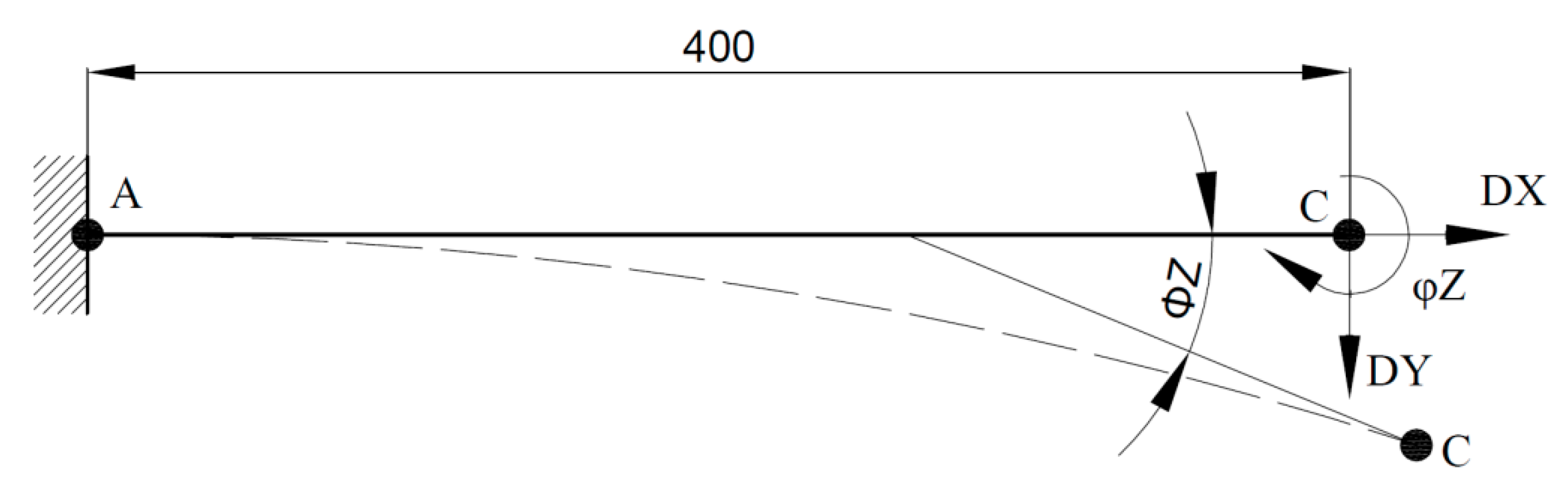
4.1. Calculation Based on European Standards

For all iterations, maximum stresses occur at point A—as shown in Figure 4. In the first iteration, the operating temperature T equals 650 °C, and pressure P acting on the internal surface of the pipes is 284 bar. The longitudinal stress distributions at the initial time in the new component (without creep phenomenon) and after 200,000 h of the component work under creep conditions are obtained from Equations (13) and (14). The maximum longitudinal stress occurs at point A. It equals σ = 158 MPa and σC = 90 MPa at the commencement and after 200,000 h of operation, respectively. Both values are not higher than the allowable values of stress fR = 319 MPa and fCR = 105.3 MPa.
The longitudinal stress distribution after 200,000 h and the maximum longitudinal stress location are presented in Figure 4. The maximum longitudinal stress (normal) σC = 90 MPa is lower than the allowable value fCR and yield strength Re. The stress concentration zone (point A) should be controlled during the superheater operation.
The second iteration is made for 700 °C. At this temperature, the maximum stress exceeds the allowable values, see Table 2. The maximum allowable operating temperature of the SH3 steam superheater is found at 665 °C.

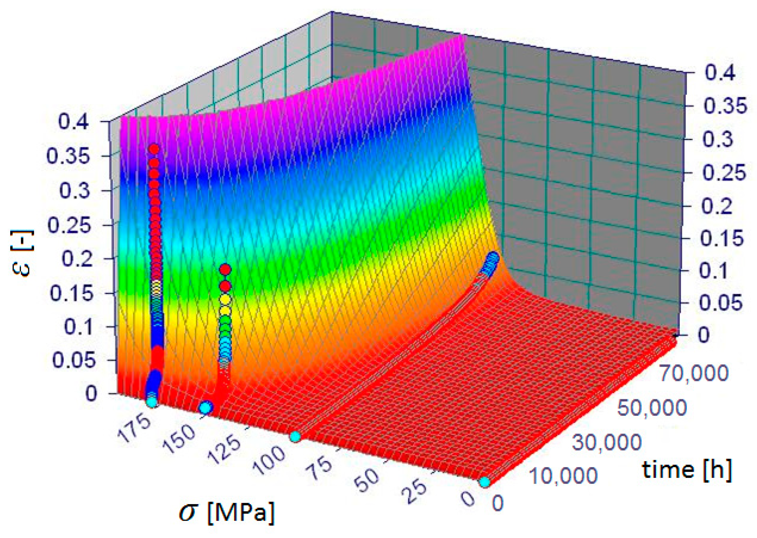
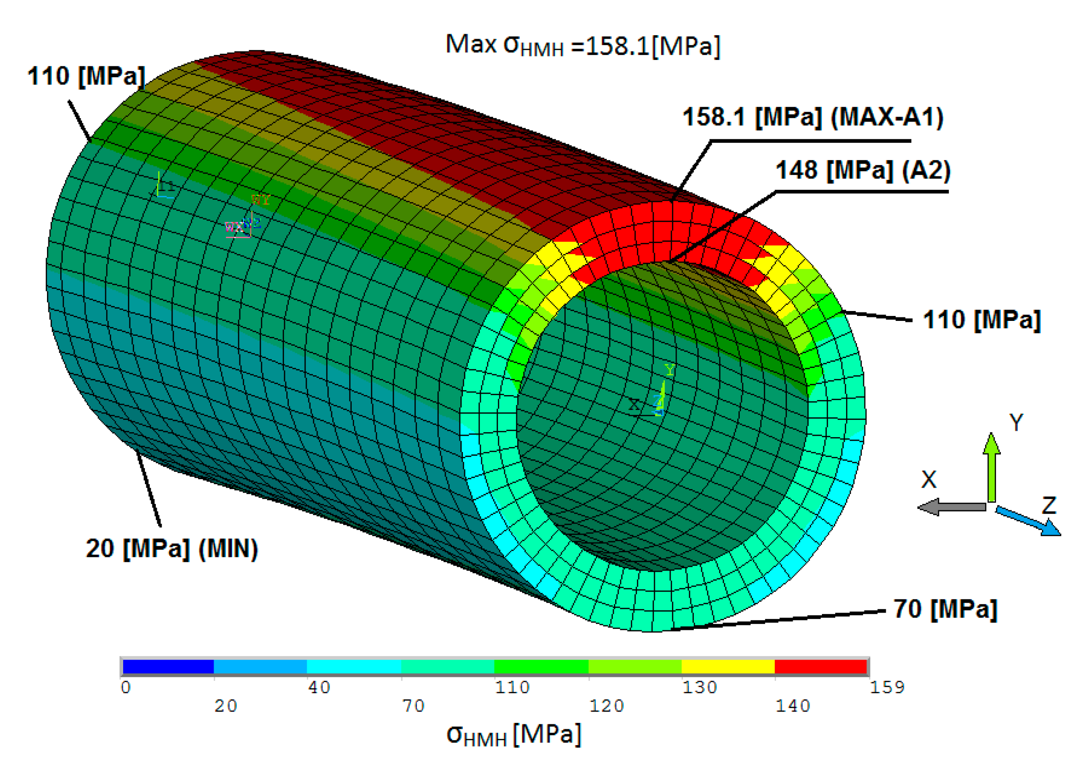
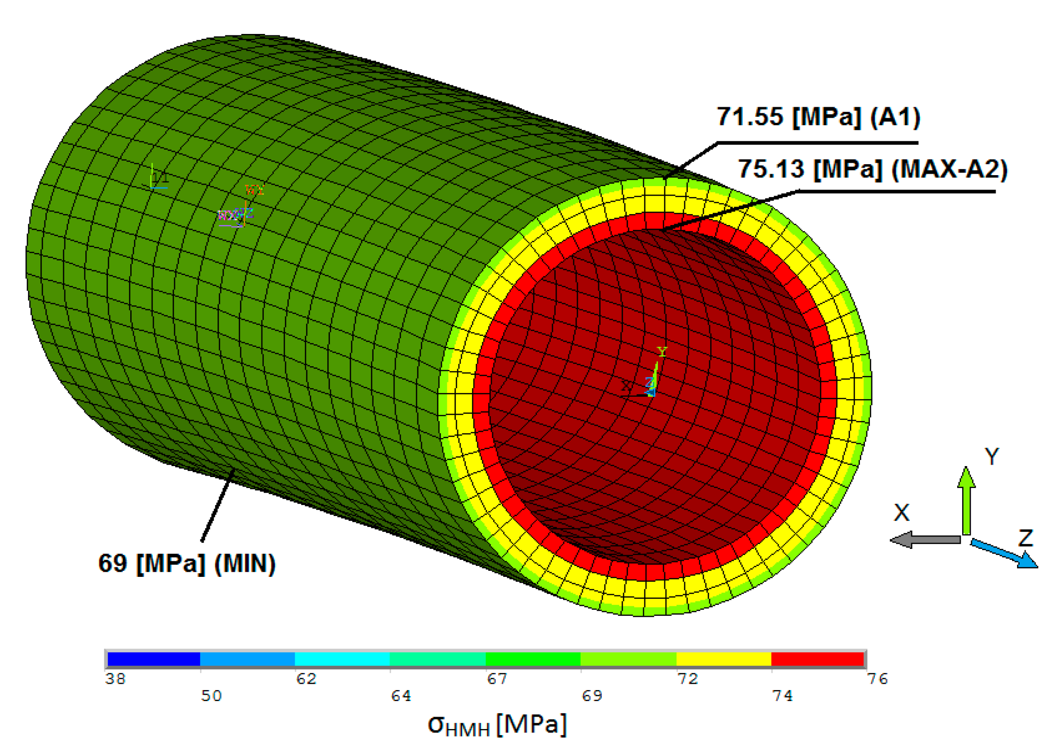
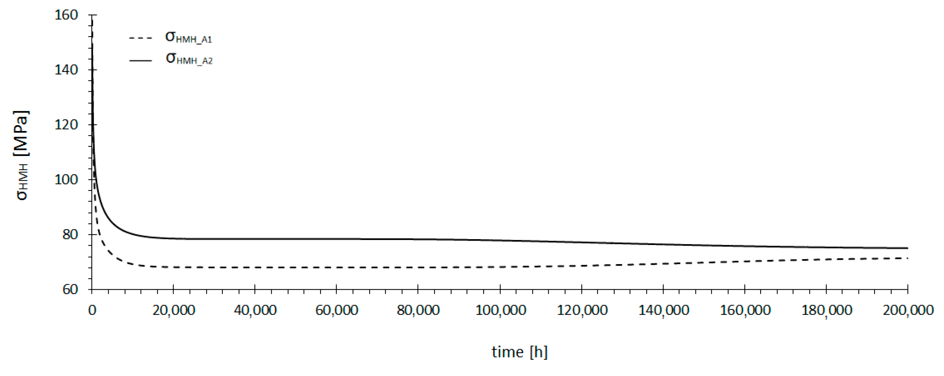
4.2. Verification of the Final Solution Based on a Detailed Analysis of the Creep Phenomenon

Based on experimental data [16,17,18,19], a creep model is built for Super 304H steel. The coefficients in Equation (15) are calculated for the optimal temperature established in the previous sub-section, i.e., 665 °C. The resulting creep model and the measured creep strain curves at 665 °C are shown in Figure 5.
A detailed analysis is conducted for the most loaded part of the superheater located close to point A, see Figure 4. The ANSYS Mechanical package is used for the strength analysis [9]. The Solid 185 finite element is used to discretize the part under consideration.
The initial analysis performed in the ANSYS program is based on a typical solution for the theory of elasticity. The boundary conditions, the equilibrium, geometric (Cauchy), and constitutive equations are used to determine the unknown displacement, strain, and stress distributions.
The developed finite element model must be loaded with pressure and end loads [22].
The end loads are represented by displacements obtained from the Auto Pipe program at point C (located 400 mm from point A, see Figure 6). In order to check the model accuracy, the Auto Pipe program end displacements and rotations (transformed to displacements) are applied to an ANSYS auxiliary pipe and equivalent stresses were compared. For the ANSYS Mechanical analysis, the boundary conditions correspond to those for the Auto Pipe—with the tension of the hanger tubes [20].
The stress distributions close to point A for the initial state and after 200,000 h are presented in Figure 7 and Figure 8, respectively. At the start of operation, the highest stress is caused mainly by bending due to the material thermal expansion. After 200,000 h, the maximum stress is lower and it is caused mainly by pressure. In order to determine the most crucial stress after 200,000 h, linearization of equivalent stresses on the wall thickness is carried out, as shown in Figure 9. The time-dependent stress relaxation for a point where stress concentration occurs is illustrated in Figure 10. At the initiation of operation the stress is considerable, but after 10,000 h, it diminishes quickly.
The time-dependent stress relaxation for a point where stress concentration occurs is illustrated as Stress σHMH = 91.2 MPa at point A1 which is reached after t = 700 h, and at point A2 after t = 2100 h. After t = 200,000 h the stresses in the superheater are much lower than the limit.
At this temperature, these stresses are large enough to produce a growth in the creep strain. The creep curves for points A1 and A2 are shown in Figure 11. The creep equivalent strains for points A1 and A2 do not exceed 1% after 100,000 h, which means that the condition presented in Section 3 is satisfied. For a stress of 91.2 MPa, corresponding to time t = 700 h at point A1, strain εHMH_A1 = 0.06%, and at point A2 (t = 2100 h) − εHMH_A2 = 0.11%.

5. Conclusions

The maximum operating temperature Tw limited by the creep phenomenon is calculated using the golden search method. Two types of strength analysis of superheater coils are described. The first type is based on European standards, which establish the maximum allowable operating temperature for steam superheater SH3 at 665 °C. The second analysis is based on the creep equation. A detailed analysis is performed to verify the optimal solution. An ANSYS analysis reveals that the initial stress value is decreased by about 55%. According to the EN 13480-3 standard, this decrease is smaller and equals 44%. A detailed creep phenomenon analysis based on the conducted creep tests shows that stresses that determine the creep process are mainly caused by pressure. The maximum stress after 200,000 h is 75.13 MPa, while the membrane stress is 73.4 MPa. Normal stresses resulting from bending are mainly the effect of thermal expansion. These stresses undergo significant relaxation because of creep. A detailed analysis of the creep phenomenon explains why the last term in Equation (14) produced by thermal expansion is much less significant compared to the last term in Equation (13). The presented calculations enable estimation of a safe operating temperature which remains constant in time. The estimated time of safe operation does not take temperature spikes into account. For this reason, pressure elements working at high temperatures must be inspected regularly to assess their wear state.

Author Contributions

P.D. conceived and designed the experiments; Ł.K. and A.D. performed the experiments; P.D. analyzed the data and wrote the paper.

Funding

This research was financed by National Science Centre, Poland, UMO‑2015/19/B/ST8/00958.

Conflicts of Interest

The authors declare no conflict of interest.

Nomenclature

Athe highest creep strain at the end of the first stage of creep, -
cpspecific heat capacity, J/(kg·K)
c1experimental constant, ln(h)
c2experimental constant, ln(h)/ln(MPa2)
c3directional factor for the second stage of creep, (ln(1/h))/MPa
c4coordinate of the t-intercept for the second stage of creep, ln(1/h)
dopipe outer diameter, mm
enpipe thickness, mm
fR, fCRallowable stresses, MPa
GLame constant, MPa
istress intensification factor, -
kthermal conductivity, W/(m·K)
K, Mcoefficients describing the destruction process intensity, -
MAmoment caused by weight and other sustained loads, Nm
MCmoment caused by thermal expansion, Nm
Ppressure, MPa
ttime, h
tIItime marking the beginning of the second stage of creep, h
Ttemperature, °C
Tmthe material melting point, °C
udisplacement vector, m
x,y,zCartesian coordinates, m
Zthe pipe section modulus, mm3
βthermal expansion coefficient, 1/K
εc(t)actual normal creep strain, -
εstrain tensor, -
λLame constant, MPa
νPoisson’s ratio, -
ρdensity, kg/m3
σnormal stress, MPa
σstress tensor, MPa
ntime step (subscripts)

References

  1. Stoppato, A.; Mirandola, A.; Meneghetti, G.; Lo Casto, E. On the operation strategy of steam power plants working at variable load Technical and economic issues. Energy 2012, 37, 228–236. [Google Scholar] [CrossRef]
  2. Rusin, A.; Wojaczek, A. Influence of thermal loads variation on the probability of waterwall tubes corrosion failure in low-emission combustion. Rynek Energii 2009, 6, 129–133. [Google Scholar]
  3. Tognoli, M.; Najafi, B.; Rinaldi, F. Dynamic modelling and optimal sizing of industrial fire-tube boilers for various demand profiles. Appl. Therm. Eng. 2018, 132, 341–351. [Google Scholar] [CrossRef]
  4. Calleja, A.; Tabernero, I.; Fernandez, A.; Celaya, A.; Lamikiz, A.; Lopez de Lacalle, L.N. Improvement of strategies and parameters for multi-axis laser cladding operations. Opt. Lasers Eng. 2014, 56, 113–120. [Google Scholar] [CrossRef]
  5. Duda, P.; Felkowski, Ł.; Dobrzański, J. An analysis of an incident during the renovation work of a power boiler superheater. Eng. Fail. Anal. 2015, 57, 248–253. [Google Scholar] [CrossRef]
  6. Duda, P.; Felkowski, Ł.; Dobrzański, J.; Purzyńska, H. Modelling the strain and stress state under creep conditions in P91 steel. Mater. High Temp. 2016, 33, 85–93. [Google Scholar] [CrossRef]
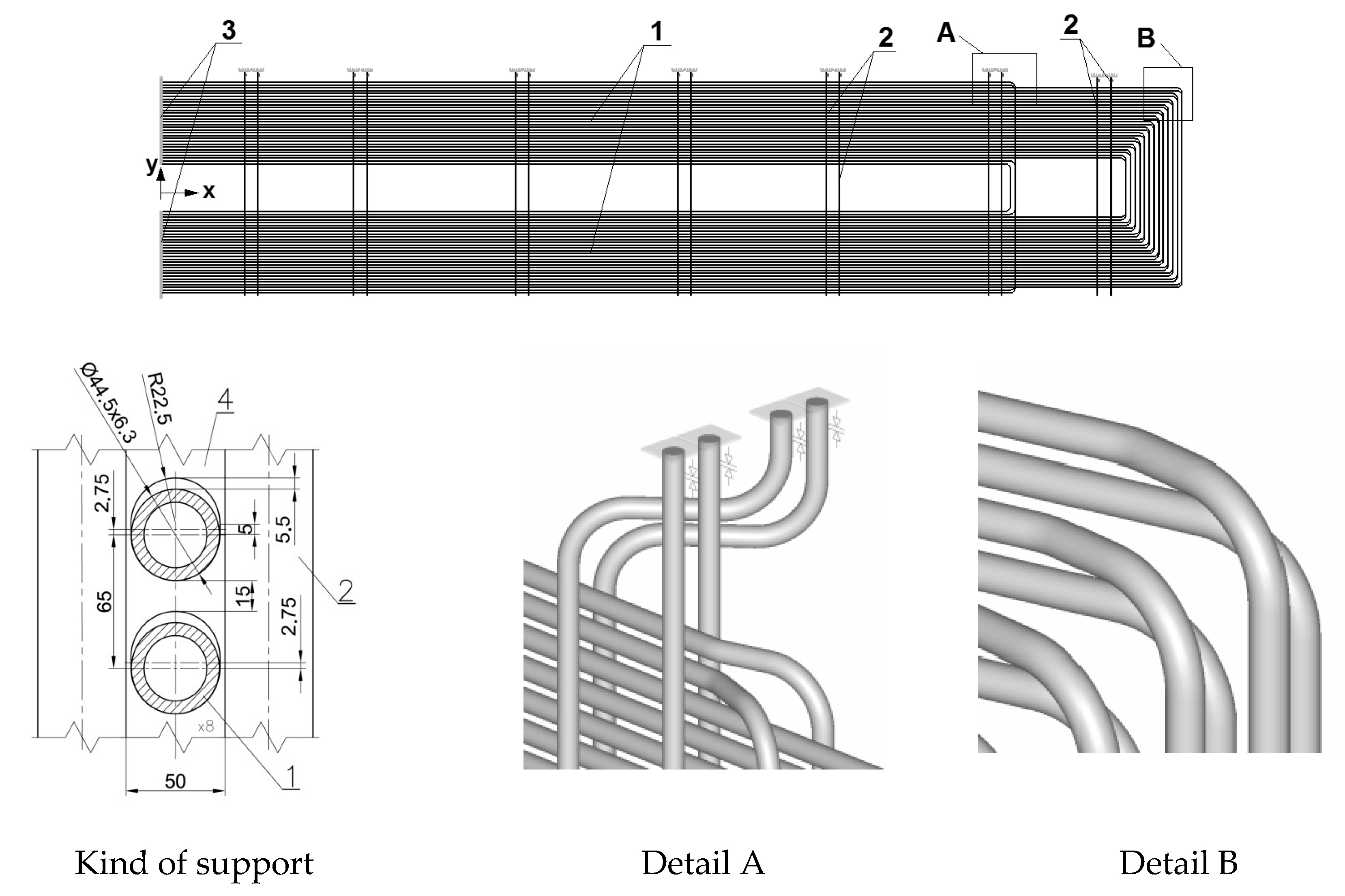
  7. RAFAKO, SA. Superheater Coils SH3 Documentation; RAFAKO SA: Racibórz, Poland, 2012. [Google Scholar]
  8. Bentley Systems. Bentley Auto Pipe V8i Select Series 5 Edition (Version 09.05.00.21); Workbook: Exton, PA, USA, 2013. [Google Scholar]
  9. ANSYS. Revision 15.0 A. In User’s Manual, Revision 15.0, Version 14; ANSYS: Canonsburg, PA, USA, 2014. [Google Scholar]
  10. The Pressure Equipment Directive (PED). Directive 2014/68/EU; L189/165-166; European Parliament: Brussels, Belgium, 2014; pp. 211–212. [Google Scholar]
  11. EN 12952-3. Design and calculation of pressure parts. In Water-Tube Boilers and Auxiliary Installations; NSAI: Dublin, Ireland, 2011. [Google Scholar]
  12. EN 13480-3. Design and calculation. In Metallic Industrial Piping; NSAI: Dublin, Ireland, 2011. [Google Scholar]
  13. Xie, L.-J.; Ren, X.; Shen, M.-X.; Tu, L.-Q. Parameter correlation of high-temperature creep constitutive equation for RPV metallic materials. J. Nucl. Mater. 2015, 465, 196–203. [Google Scholar] [CrossRef]
  14. Naumenko, K.; Altenbach, H. Modelling of Creep for Structural Analysis; Springer: Berlin, Germany, 2007; pp. 1–15. [Google Scholar]
  15. Osocha, P. Determination of the Extent of Damage to the Boiler Thick-Walled High-Pressure Elements. Ph.D. Thesis, Institute of Thermal Power Engineering-Cracow University of Technology, Cracow, Poland, 2009. [Google Scholar]
  16. Sroka, M.; Zieliński, A.; Mikuła, J. The service life of the repair welded joint of Cr-Mo/Cr-Mo-V. Arch. Metall. Mater. 2016, 61, 969–974. [Google Scholar] [CrossRef]
  17. Zieliński, A.; Sroka, M.; Miczka, M.; Śliwa, A. Forecasting the particle diameter size distribution in P92 (X10CRWMOVNB9-2) steel after long-term ageing at 600 and 650 °C. Arch. Metall. Mater. 2016, 61, 753–760. [Google Scholar] [CrossRef]
  18. Sroka, M.; Zieliński, A.; Hernas, A.; Kania, Z.; Rozmus, R.; Tański, T.; Śliwa, A. The effect of long-term impact of elevated temperature on changes in the microstructure of Inconel 740H alloy. Metalurgija 2017, 56, 333–336. [Google Scholar]
  19. Zieliński, A.; Sroka, M.; Hernas, A.; Kremzer, M. The effect of long-term impact of elevated temperature on changes in microstructure and mechanical properties of HR3C steel. Arch. Metall. Mater. 2016, 61, 761–766. [Google Scholar] [CrossRef]
  20. Felkowski, Ł.; Duda, P.; Węglowski, B. Analysis of Power Systems; Węglowski, B., Duda, P., Eds.; Cracow University of Technology Press: Kraków, Poland, 2013; pp. 387–401. [Google Scholar]
  21. ASME Case 2328-2. Cases of ASME Boiler and Pressure Vessel Code; ASME: New York, NY, USA, 2010. [Google Scholar]
  22. Miroshnik, R.; Shaked, Y.; Elmakis, D. Life Assessment Evaluation of piping branch connection under creep & fatigue. Int. J. Press. Vessels Pip. 1997, 8, 147–154. [Google Scholar]
Figure 1. Superheater SH3 model (data from [7]).
Metals 08 00892 g001
Figure 2. Boundary conditions of superheater SH3 hanger.
Metals 08 00892 g002
Figure 3. Method of superheater SH3 support: 1—Anchor, 2—Guide, 3—Cut Short.
Metals 08 00892 g003
Figure 4. Ratio of longitudinal stress to allowable stress for the superheater after 200,000 h of operation under creep conditions.
Metals 08 00892 g004
Figure 5. Real measured and modeled creep strains [-] for Super 304H steel in the temperature of 665 °C.
Metals 08 00892 g005
Figure 6. ANSYS submodel.
Metals 08 00892 g006
Figure 7. Distribution of equivalent stresses at the initial time of operation (T = 665 °C).
Metals 08 00892 g007
Figure 8. Distributions of equivalent stresses after 200,000 h (T = 665 °C).
Metals 08 00892 g008
Figure 9. Linearized equivalent stress (HMH) after 200,000 h (T = 665 °C).
Metals 08 00892 g009
Figure 10. Relaxation of equivalent stress.
Metals 08 00892 g010
Figure 11. Creep curve for points A1 and A2.
Metals 08 00892 g011
Table 1. Chemical composition of Super 304H steel.
Chemical Composition (%)—ASME Code Case 2328-1
CSiMnPSCuCrNiNbBNAl
0.07–0.13Max
0.30
Max
1.00
Max
0.0040
Max
0.0010
2.50
3.50
17.0
19.0
7.5
10.5
0.30
0.60
0.0001
0.0010
0.05
0.12
0.0003
0.0030
Table 2. Maximum longitudinal stress.
Temperature
(°C)
Stress
σ (MPa)
Stress
σC (MPa)
Yield Strength (MPa)Allowable Stress (MPa) (See Section 3.1)
fRfCRσC/fCR
65015890172319.0105.30.85
70016792160252.558.31.58
66516090160296.591.20.99

