Abstract
The behavior of MnS, a significant non-metallic inclusion in steel with low sulfur content, is poorly understood, in particular, how the MnS inclusion becomes a favorable secondary phase. To clarify how the sulfur content in DH36 structural steel affects the behaviors of MnS, and the steel properties, samples containing 20–380 ppm sulfur were melted, and the ingots were rolled in a semi-industrial single-roll mill. According to experiments using optical microscopy (OM), scanning electron microscopy (SEM), an automatic inclusion analysis system, and transmission electron microscopy (TEM), the morphology of MnS inclusions changed from thread-shaped to spherical- or spindle-shaped with decreasing sulfur content, and their size and number also decreased. The steel with 20 ppm S contained much more nanoscale MnS, whose pinning effect created a fine grain size in the steel. The reason is that the temperatures of maximum nucleation rate and fastest precipitation of MnS in this sample (900 °C and 920 °C, respectively) are much lower than the soaking temperature. Compared to samples with 70–380 ppm sulfur, the sample with 20 ppm sulfur content demonstrated the highest yield strength, tensile strength, and impact energy. Finally, the industrially produced DH36 samples were analyzed, and the steel with the lower S content had a higher stability and yield strength, in agreement with our laboratory results.
1. Introduction
DH36 is a high-strength structural steel widely used in the shipbuilding industry, especially naval warship structural applications. Since the 1980s, it has demonstrated superior mechanical properties through controlled rolling and controlled cooling, which are often called the thermomechanical controlled processes (TMCP) [1]. Moreover, the obtained final microstructure and mechanical properties are closely connected with the chemical composition of the steel. The content of sulfur (S), which is commonly considered to harm the steel properties, is increasingly being restricted in ship steel. For example, in the new modified and improved standard specification in the United States, the maximum S content has decreased from the original values of 0.006% and 0.008%, to 0.004%, a drop of about 33.3% and 50%, respectively, in order to meet the harsh marine environment [2].
The decreased S content has a direct effect on MnS precipitation in the steel. MnS is a common type of deformable non-metallic inclusion in steel. These inclusions elongate easily during hot rolling, resulting in poor transverse toughness and stress corrosion cracking of the medium plate [3,4]. In fact, since the 1960s, researchers have paid much attention to MnS and established the general response of MnS inclusions under thermal treatment. Flowers and Karas [5,6] first studied MnS inclusions in Fe-3%Si alloy by heating. McFarland and Cronn [7] investigated the shape change of elongated α-MnS when the specimens were subjected to heat treatment. Murty et al. [8,9,10] observed three stages of shape change for elongated α- and β-MnS in high-sulfur steel: (1) cylinderization, (2) ovulation, and (3) coarsening. Liu [11] observed a great amount of nanoscale sulfide in CSP low-carbon steel with low S content. It is very interesting to note that the yield strength of steel with low S content is higher than that of conventional hot-rolled sheet steels, because this indicates that the nanoscale sulfides may actually improve the mechanical property of steels. However, the relations between the sulfur content in steels and the MnS inclusion characteristics, such as its population density, size, and morphology, are not very clear. In particular, there is only very limited understanding of how MnS would become a favorable secondary phase at low S content.
In the present paper, we comprehensively examined the effect of sulfur content (20–380 ppm) in DH36 steel on the MnS precipitation in laboratory experiments. In particular, we intend to provide a bird’s eye view of the nanoscale MnS, and its effect on steel with very low S contents. Furthermore, the influences of S content on the microstructure and mechanical properties of DH36 steel were also discussed. Simultaneously, the precipitation mechanism of nanosized MnS was studied in terms of the underlying thermodynamics and dynamics, on which the discussion of grain refinement mechanisms was based.
2. Materials and Methods
2.1. Materials
To examine the effects of sulfur contents on the MnS phase and the mechanical properties of steel, an industrial DH36 steel with low S and oxygen (O) contents was used as base metal, and melted in a 20 kg vacuum induced furnace. During the smelting process, the pressure in the furnace was kept lower than 60 Pa and the temperature was raised to 1600 °C at a rate of 20 °C/min. Thereafter, a moderate amount of FeS (analytical pure) was added through a built-in charging device to adjust the S content to between 20–380 ppm. The temperature was maintained at 1600 °C for about 5 min after FeS addition, to ensure its homogeneity in the melt. Then, the melt was poured into an iron crucible under vacuum. The chemical compositions of the steels are shown in Table 1.

Table 1.
Chemical compositions of steel samples (wt %).
The hot working was performed as two rolling processes in a semi-industrial single-roll mill, as shown in Figure 1, in order to simulate the thermal history of the hot-rolling process in actual plants. Firstly, the ingots were forged into a cuboid shape with the approximate dimensions of 280 mm × 150 mm × 60 mm. It was then heated up to 1150 °C in a muffle furnace, and maintained for 50 min. The initial rolling temperature was approximating 1100 °C, and 60% reduction in total was performed by three passes (25%, 25% and 15%, respectively). The final temperature for the first rolling was near 950 °C. About 10 min later, the second rolling process was performed by adjusting the rolling temperature to approximately 900 °C. The final thickness of the plate is 8.4 mm after four rolling passes. The final rolling temperature was about 800 °C. Afterwards, the rolled plates were air-cooled (AC) to room temperature.
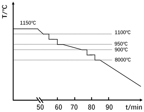
Figure 1.
Schematic of controlled rolling schedule.
2.2. Microstructural Characterization
After rolling and cooling, the specimens were machined to 10 mm × 10 mm × 8.4 mm from the center of the plate, and polished for microstructural observation using OM (Leica, Wetzlar, Germany) and SEM (Carl-Zeiss, Oberkochen, Germany). The average grain size of the specimens was calculated using the Image-Pro Plus software. The final value was the averaged measurement from 20 photos under 500 times and 1000 times, respectively, for each sulfur content. Specimens for grain size measurement were polished and etched with a Nital etchant (ethanol + 4 vol % nitric acid) to reveal the grain boundary. Non-metallic inclusions in these specimens were analyzed by an automatic inclusion analysis system (EV018-INCAsteel, Oxford Instruments, Oxfordshire, United Kingdom) to measure the equivalent diameter, number, and aspect ratio of MnS on the specimen surface in a scanning area of 5 mm × 5 mm. In the present work, only the data of MnS were taken into account in order to exclude the effect of oxides. Furthermore, nanosized MnS inclusions were observed and identified by an FEI Tecnai F20 TEM system using carbon film replicas, which were prepared by grinding the samples to 2000 grit, and then polishing the surface with diamond paste. The surface was etched in 4 vol % Nital solution, and carbon was evaporated onto the surface under vacuum. The thickness of the carbon film was controlled at about 20 nm. Finally, the carbon film replica was removed with 8 vol % Nital solution, and then cleaned with deionized water.
2.3. Mechanical Testing
The tensile direction of the tensile specimens was parallel to the rolling direction, and the length of Charpy impact specimens was parallel to the rolling direction of the plate. Tensile samples with the diameter of 20 mm and length of 150 mm were tested at room temperature on an MTS CMT4105 testing machine, as shown in Figure 2. The dimensions of Charpy specimens with V-shaped opening are shown in Figure 3. Each reported value is the mean value of three replicates.
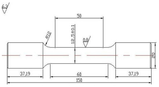
Figure 2.
Dimensions of tensile specimen in mm.

Figure 3.
Dimensions of Charpy specimens in mm.
3. Results
3.1. MnS Inclusions in Rolled Steel
Figure 4 shows the size distributions of MnS inclusion in steels with 20, 70, 150, and 380 ppm sulfur content. The equivalent diameter, the diameter of a circle with the same area, was measured by the automatic inclusion analysis system. It should be pointed out that data of detected oxide or oxide-MnS dual phase inclusions have been excluded in the results of Figure 4. At 20 ppm sulfur content, MnS with sizes in the interval of 1–2 μm occur with the highest frequency, while those at 70, 150, and 380 ppm sulfur contents are 1–3.7, 1.8–4.5, and 7–10 μm, respectively. Moreover, there were lots of MnS inclusions with size larger than 10 μm in the sample with 380 ppm S.
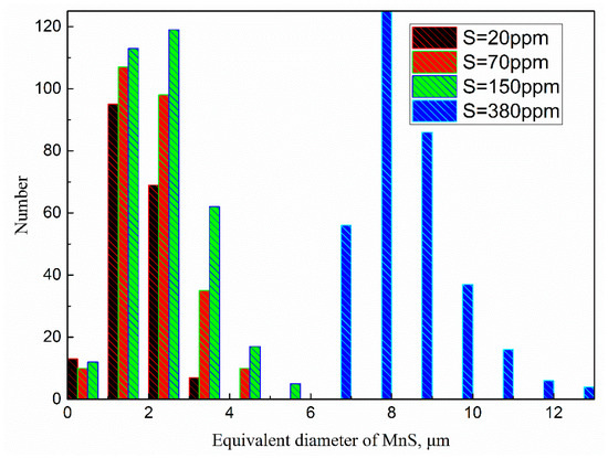
Figure 4.
Size distributions of MnS in different steel samples.
Figure 5 displays the effects of sulfur contents on the average size and number of MnS. Using the automatic inclusion analysis system, the average sizes and number of MnS both increase sharply with sulfur contents in the tested samples. When the S content was 20, 70, 150 and 380 ppm, the average diameter of MnS was 1.87, 2.05, 2.43 and 8.05 μm, respectively. At the same time, the number of MnS inclusions in the 5 mm × 5 mm area are increased from 184 to 260, 328, and 450.
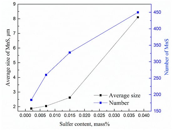
Figure 5.
Changes in the average size (left y-axis) and number (right y-axis) of MnS inclusions with the S content.
3.2. Effects of Sulfur Content on MnS Morphology
Figure 6 shows three typical MnS inclusion morphologies that were observed by SEM in all the specimens: (a) spherical, (b) spindle-shaped, and (c) thread-shaped. These inclusions were non-faceted with a smooth surface. Our previous work [12] established a theoretical model to predict the morphology of second phase particles in steel, by introducing a dimensionless Jackson α factor. The inclusion is non-faceted in morphology when its Jackson α factor is less than 2. Typically, the Jackson α factor for MnS inclusion is between 0.44 and 0.87 [12].

Figure 6.
Typical morphologies of MnS inclusions in the specimens: (a) spherical; (b) spindle-shaped; and (c) thread-shaped.
Figure 7 shows the aspect ratio distribution of MnS inclusion in the steel with different sulfur contents. In the sample with 20 ppm S, most of MnS particle had aspect ratio lower than 2. At higher sulfur content contents, the number of MnS particles with an aspect ratio larger than 2 obviously increased. Figure 8 shows the relationship among the total number of MnS, the percentage of MnS particles with aspect ratio less than 2, and the sulfur content. It is known that MnS inclusions with spindle and spherical shapes have the least negative effect on the performance of steel, while the thread-shaped ones are more harmful. Moreover, the MnS is spindle-shaped when the aspect ratio is 2 and spherical when the aspect ratio is 1 [13]. Increasing the sulfur content in DH36 structural steel increases the number of thread-shaped MnS inclusions, indicating that it alters the morphology of MnS from spindle and spherical shapes to thread-shaped. At the lowest sulfur content (20 ppm), 90% of the MnS inclusions have an aspect ratio less than 2.
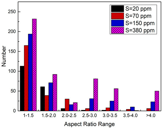
Figure 7.
Aspect ratio distribution of MnS inclusion in the steel with different sulfur content.
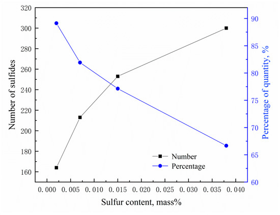
Figure 8.
Number of MnS inclusions (left y-axis) and percentage of them with aspect ratio <2 (right y-axis) in steels with different sulfur contents.
Van Eeghem [14] studied the relationship between the oxygen content and MnS morphology in steel with high S contents, and found that when w[O] > 120 ppm, the sulfide was spherical-shaped. The present results indicate that the MnS inclusions were also mainly spherical when the S content was low, with a lower oxygen content.
3.3. Effects of Sulfur Content on Steel Microstructure and Properties
Figure 9 shows microstructures of rolled samples with different sulfur contents. The white regions are ferrites, and the black regions are pearlites. The fraction of pearlites is approximately 30% for all four samples. The relationship between the grain size and sulfur content is shown in Table 2. It should be pointed out that the grain size is the average value from both ferrite and perlite. With the increase of sulfur content, the grain size also increases. Compared to the sample with 380 ppm sulfur, the sample with 20 ppm sulfur showed a grain size reduction of 54%.
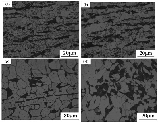
Figure 9.
Microstructures of rolled specimens at different sulfur contents: (a) 20; (b) 70; (c) 150; and (d) 380 ppm.

Table 2.
Relationship between grain size and sulfur content.
The measured yield strength, tensile strength, and impact energy for different steel samples can be seen in Table 3. With the increase of S content, the yield strength, the tensile strength, and the impact energy all decrease, but the elongation increases. At 20 ppm sulfur content, the grain size and MnS inclusion size are small enough that the steel shows better mechanical performance than samples with higher sulfur contents.

Table 3.
Relationship between sulfur content and mechanical properties: yield strength (Re), tensile strength (Rm), elongation (A), and the Charpy-V type notch impact absorption work (Akv).
4. Discussion
4.1. Thermodynamics of MnS Precipitation
The chemical reactions to form MnS inclusions and their free energies [16] are as follows:
where (s), (g), , and are the solid, gas, and standard Gibbs free energy of δ-ferrite and standard Gibbs free energy [16] of austenite, respectively.
By combining Equations (1) to (5), the following Equations (6) and (7), can be deduced.
Equation (10) describes the reaction equilibrium, where [Mn] and [S] mean dissolved Mn and S atoms in liquid steel, , , , and are the thermodynamic equilibrium constant, activity, activity coefficient, and first-order interaction coefficient, respectively.
The equilibrium solubility product of MnS is expressed as a function of reciprocal temperature in δ-ferrite and austenite, as given in Equation (14) and Equation (15). The final formula can be deduced from the equilibrium solubility product and actual solubility product.
where and are the equilibrium solubility product and actual solubility product, respectively. When < , and MnS is generated. When > , and MnS decomposes.
Using the Thermo-Calc software and the leverage model, the starting temperature of δ-ferrite and austenite phases and the precipitation temperature of MnS were obtained at different S contents, as shown in Table 4.

Table 4.
Relationship between starting temperature of each phase and sulfur contents.
From Table 4, the precipitation temperature of MnS is characterized as follows:
- (1)
- w[S]% > 0.015 mass %: MnS is generated in the δ-ferrite.
- (2)
- w[S]% < 0.007 mass %: MnS is generated in the austenite.
- (3)
- The temperature at which MnS starts to precipitate gradually increases with the sulfur content.
- (4)
- Controlling sulfur content is the most effective measure to ensure that MnS precipitates in δ-ferrite.
Takada et al. [17] found that when the S content is around 110 ppm, MnS is precipitated at the critical temperature of the δ-ferrite and austenite. For sulfur content up to 0.01%, most of the MnS inclusions are spherical. The higher the sulfur content, the larger the area with thread-shaped MnS. According to the above conclusions and the thermodynamic calculation results, we could account for Figure 6, Figure 7 and Figure 8 as follows. The controlling element in the precipitation process of MnS is Mn. Moreover, the diffusion rate of manganese (Mn) in δ-ferrite is much faster than in austenite [18,19]. Hence, the MnS precipitated in δ-ferrite has a larger size than that precipitated in austenite. Increasing the sulfur content leads to an increase in MnS inclusion size, as well as greatly increased cluster distribution of thread-shape MnS. Therefore, the distribution of MnS will be less favorable at higher S contents, leading to poor properties in steel, as shown in Table 3.
4.2. Kinetics of MnS Precipitation
In the sample with 20 ppm sulfur, a large number of nanosized MnS inclusions were found by applying TEM equipped with energy disperse spectroscopy (EDS), as shown in Figure 10. However, such nanosized MnS inclusions were rarely detected in samples with other sulfur contents. In particular, hardly any nanoscale MnS was observed in the samples with 150 ppm and 380 ppm S. Therefore, the reasons for the formation of nanoscale MnS were further analyzed in terms of the dynamics.
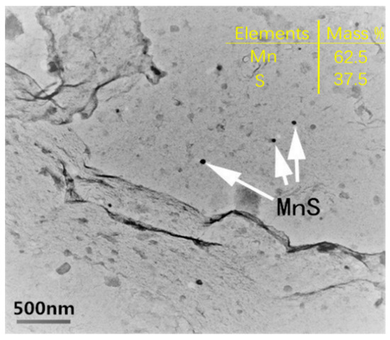
Figure 10.
TEM image of nanosized MnS with 20 ppm sulfur content.
The standard formation free energy of MnS in the iron-based system at different temperatures can be calculated from Equations (17) and (18) [16].
where δ, , , , R, and T are δ-ferrite, austenite, the mass fraction of the total Mn, mass fraction of the total S, universal gas constant (8.314 ± 0.00026 J/(mol·K)), and absolute temperature (K), respectively.
The chemical driving force associated with unit volume of MnS is approximately given by
where and are the chemical driving forces associated with the unit volume free energy and molar volume, respectively. Moreover, MnS has a fcc structure, and its lattice parameters and linear coefficients are listed in Table 5. The molar volume can be deduced from these parameters.

Table 5.
Main kinetic parameters of MnS formation in steels [16].
Neglecting the influence of elastic energy in the quantitative calculation, the critical free energy for nucleation (), the critical diameter of MnS (), the obtained nucleation rate, and the starting time of the precipitation from Ref. [16] are given by Equations (20)–(23).
where , , , , and are the interfacial free energy of the nucleus–matrix interface, the diffusion activation energy of Mn atoms, Boltzmann constant (1.3806505 × 10⁻²³ J/K), the amount of time to reach 5% during homogeneous nucleation, and the start time of homogeneous nucleation, respectively.
The precipitation amount-temperature-time (PTT) [20] curves of MnS precipitation with different S contents are shown in Figure 11. It is known that the PT curve usually has a “c” shape, and the range of effective precipitation temperature is in the vicinity of the nose point temperature, where the precipitation starts and finishes most quickly [20]. At 380 ppm sulfur content, the fastest precipitation temperature is 1480 °C. At 150, 70, and 20 ppm sulfur content, these temperatures are 1300 °C, 1080 °C, and 920 °C, respectively. The soaking temperature of DH36 structural steel is about 1150 °C, which is much higher than the temperatures of fastest MnS precipitation at 20 ppm S. Moreover, during the Ostwald ripening of MnS, S is the controlled element when w[Mn]% > 0.7 [21]. Given the above, a low precipitation temperature and a slow Ostwald ripening rate provide the condition to precipitate nanosized MnS when the sulfur content is 20 ppm.
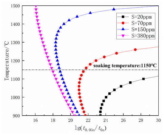
Figure 11.
Precipitation amount-temperature-time (PTT) diagram of MnS precipitation.
4.3. Contribution of MnS to Grain Refinement
Controlling the S content is the key to decreasing the MnS inclusion size and improving their morphology, mitigating the bad influence of sulfide and, indeed, changing MnS into a favorable second phase.
Zener [22] first gave the basic quantitative principle of the second-phase particles in steel that could prevent the austenite grain coarsening. Gladman [23] developed a theoretical model of the energy changes accompanying grain boundary movement, which was dependent on the volume fraction and the size of second phase particles.
where is the average equivalent diameter of grain, and d and f are the mean diameter and volume fraction of second phases, respectively. Moreover, Z is the factor of grain size. Austenite grains are coarse and uniform in the holding process. Hence, the value of Z can be taken as 1.7 [16].
The volume fraction of MnS can be approximated by the following equations.
where and are the atomic weights of Mn and S elements, respectively.
Equation (29) is known as the formula for solving the mass percentage of MnS.
where and are the densities of Fe and MnS, respectively.
Mn is the main controlled element during MnS precipitation [16]. Equations (30) and (31) give the diffusion coefficients of Mn elements in the δ-ferrite and austenite, respectively.
By replacing −1.28994 in Equation (23) with , the curve of temperature-sedimentation completion time (t0.95) can be obtained. At 70 and 20 ppm sulfur contents, the precipitation temperatures of MnS are much lower than the soaking temperature. Hence, the completion time of MnS transition at 1200 °C must be calculated to estimate the pinning effect of MnS. Referring to Figure 12, the completion times of MnS transition are estimated to be 250, 150, 40, and 4 s for 380, 150, 70, and 20 ppm S content, respectively.
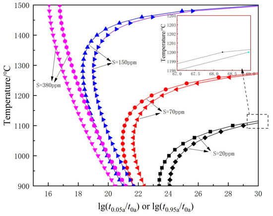
Figure 12.
Curves for starting and completion of precipitation of MnS with different S contents.
Equation (32) is the formula for calculating the radius of the precipitate. As the diffusivity of Mn is lower than that of S in δ-ferrite and austenite, diffusion of Mn is assumed to be the controlled element for MnS precipitation.
where is the rate constant with a typical value of 0.123 [16]. By combining Equations (30) to (32), the radius of MnS can be deduced. When the S content varied from 20, 70, 150, to 380 ppm, the radius of MnS is 0.01, 0.50, 1.41, and 4.02 μm, respectively. With the decrease of S content, favorable nanoscale MnS can be obtained, as shown in Figure 10.
Table 6 lists the values of various parameters of MnS at 1150 °C. There seems to be a significant difference between the calculated values of equivalent diameters (especially for 20 and 70 ppm S) and the experimental one shown in Figure 4. This is because the results in Figure 4 were measured by an automatic inclusion analysis system that only detects inclusions larger than ca. 1 μm in size, but not the nanoscale MnS, while the equivalent diameters in Table 6 are calculated theoretically by including both micrometer-scale and nanoscale MnS particles. Since the samples with 20 and 70 ppm S contain a larger number of precipitated nanoscale MnS particles, the measured inclusion equivalent diameter and calculated results appear very different. For the samples with 150 and 380 ppm S, there was nearly no nanoscale MnS precipitating and, thus, the measured results and calculations are in much better agreement.

Table 6.
Main parameters of MnS at 1150 °C.
As mentioned before, the pinning effect is closely correlated with the volume fraction and the equivalent diameter of the second phases. Table 6 shows that MnS can pin the boundary of austenite effectively and refine the austenite grain. At 20 ppm sulfur content, MnS also has a strong pinning effect, even though its volume fraction is very small. This is because with a reduction of S content, the diameter of MnS is significantly reduced. Clearly, the weak pinning is no longer working when the S content is high.
In Equations (33) through (34), considering the rolling system in Figure 1, one can calculate the final ferrite grain size after the rolling schedule.
where , , , and stand for rolling reductions, final ferrite grain size after rolling cooling, austenite grain sizes prior to deformation, and deformation temperature. The values of a, b, c, A, and B are taken as 90, 0.7, 0.027, 7.5, and 15, respectively [24].
can be obtained using Equation (33), and it is the ferrite grain size after the first pass. Substituting this value in Equation (34), one can solve for , which is regarded as the austenite grain size of the second pass. Finally, Equation (33) is used again.
Figure 13 shows the relationship between the final ferrite grain size and different sulfur contents with the same rolling schedule. To better analyze the pinning effect of MnS, the calculation ignores the influence of (Ti, Nb)(C, N) particles. This is the main cause of the difference between the measured and predicted values. With the increase of sulfur content, this difference decreases gradually, which indicates that the pinning effect of MnS also gradually decreases to zero, as shown in Table 6.
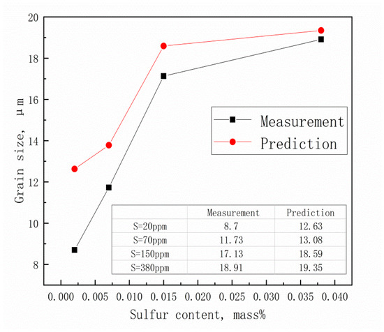
Figure 13.
Measured and predicted values of after two-pass deformation.
5. Industrial Production Results
Industrial production was carried out at Shangdong Iron and Steel Company LTD. The process flow is shown in Figure 14. Referencing the results of laboratory experiments, the start rolling temperatures of 1100 °C for recrystallization austenite region and 900 °C for non-recrystallization region were used. The total reduction was about 60 %. The finish rolling temperature was controlled at a range of 630–670 °C.
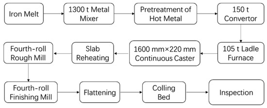
Figure 14.
Process flow of DH36 structural steel in the industrial production.
Tensile testing and component analysis of DH36 steel with different heats were measured in this study. Table 7 gives the composition range of the industrially produced steel. The S contents range from 20 to 220 ppm with different furnace times. Considering the actual technological level of the steel mill and the results of laboratory experiments, we divided 300 heats of industry data into two groups: one with low sulfur content (<40 ppm) and the other with high sulfur content (>70 ppm). Then, the yield strength data of these two groups were further analyzed using the quality control (QC) chart.

Table 7.
Composition range of DH36 steel (in wt %) from industrial production.
The QC chart was developed by Dr. Walter A. Shewhart during the 1920s, and it makes possible the diagnosis and correction of many production problems, substantially improving the product quality and reducing spoilage and rework [25]. In this paper, the QC chart is used to analyze the stability of the actual production in the factory. Each point is composed of five random data points. Here, the range is the difference between the minimum and maximum in a subgroup; UCl and LCL are the upper control line and lower control line, respectively; and CL is the average value of all data points.
Figure 15 shows the effect of S content on yield strength. The yield strength fluctuates violently, and the production is very unstable when w(S) ≥ 0.007%. Interestingly enough, all data points are distributed within the control line, and have a higher mean yield strength when w(S) ≤ 0.004%. Thus, the yield strength of the steels in industrial production strongly supports the results in our laboratory.
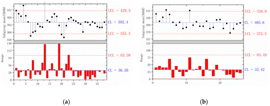
Figure 15.
QC analysis of yield strength with different S contents of (a) w(S) ≥ 0.007%; (b) w(S) ≤ 0.004%.
Interestingly, Liu et al. [11] also observed a great amount of nanoscale sulfide in a low-carbon steel with low S content in the CSP process, and found that they could improve the steel yield strength to two times higher than that of conventional hot-rolled sheet steels. Their findings are in agreement with our results, indicating that nanoscale sulfide precipitates, formed by maintaining a low S content, would also increase the strength and toughness of other types of steel. Therefore, we can improve the mechanical property of some steels by controlling the sulfur content to be very low.
6. Conclusions
Laboratory experiments were carried out to clarify the effect of S content on the MnS inclusions and the mechanical properties of DH36 structural steel. The experimental data and discussion yielded the following results.
- (1)
- Decreasing the sulfur content in DH36 steel alters the morphology of MnS from thread-shaped to spherical- or spindle-shaped, and also decreases the average size and number of MnS. For the steel with 20 ppm sulfur content, the ratio of spherical MnS increases to 90%. Compared to steels with 70, 150, and 380 ppm sulfur, the sample with 20 ppm sulfur had the most favorable mechanical properties.
- (2)
- In the DH36 steel with 150 and 380 ppm sulfur contents, MnS precipitates in δ-ferrite; while, in those with 70 and 20 ppm sulfur content, MnS precipitates in austenite. Plenty of nanoscale MnS particles were observed by TEM in the steel with 20 ppm S, and the grain size becomes finer due to its pinning effect.
- (3)
- The temperatures of maximum nucleation rate and fastest precipitation of MnS are much less than the soaking temperature when the S content is 20 ppm, which is the main reason for the formation of nanoscale MnS. Controlling the S content is the key to decrease the size of MnS, improve the morphology of MnS, and reduce the negative influence of sulfide on the properties of DH36 steel.
Author Contributions
Conceptualization, W.Y. and S.D.; Data curation, X.S.; Formal analysis, S.L.; Funding acquisition, J.G.; Investigation, W.Y.; Methodology, J.G.; Project administration, H.G.; Resources, J.W.; Supervision, H.G.; Validation, Z.Z.; Writing—original draft, J.G. and W.Y.; Writing—review & editing, J.G.
Funding
The authors express their thanks to National Science Foundation for Young Scientists of China (51704021), China postdoctoral fund (2018M630071), Fundamental Research Funds for the Central Universities (FRF-TP-16-079A1), and Joint Funds of National Natural Science Foundation of China (U1560203) for their kind financial support. This study was also supported by Beijing Key Laboratory of Special Melting and Preparation of High-End Metal Materials.
Conflicts of Interest
The authors declare no conflict of interest.
References
- Ouchi, C. Development of steel plates by intensive use of TMCP and direct quenching processes. ISIJ Int. 2001, 41, 542–553. [Google Scholar] [CrossRef]
- Czyryca, E.J.; Link, R.E.; Wong, R.J.; Aylor, D.A.; Montem, T.W.; Gudas, J.P. Development and certification of HSLA-100 steel for naval ship construction. Nav. Eng. J. 1990, 102, 63–82. [Google Scholar] [CrossRef]
- Shao, X.; Wang, X.; Ji, C.; Li, H.B.; Yang, C.; Zhu, G.S. Morphology, size and distribution of MnS inclusions in non-quenched and tempered steel during heat treatment. Int. J. Miner. Metall. Mater. 2015, 22, 483–491. [Google Scholar] [CrossRef]
- Ray, G.P.; Jarman, R.A.; Thomas, J.G.N. The influence of non-metallic inclusions on the corrosion fatigue of mild steel. Brit. Corros. J. 1985, 15, 226–227. [Google Scholar] [CrossRef]
- Flowers, J.J.W.; Karas, S.P. Coalescence of sulfides during secondary growth in 3% silicon—Iron. J. Appl. Phys. 1967, 38, 1085–1086. [Google Scholar] [CrossRef]
- Flowers, J. Grain growth inhibition by spherical particles with a distribution of sizes. IEEE Trans. Magn. 1979, 15, 1601–1603. [Google Scholar] [CrossRef]
- McFarland, W.H.; Cronn, J.T. Spheroidization of type II manganese sulfides by heat treatment. Metall. Trans. A 1981, 12, 915. [Google Scholar] [CrossRef]
- Wilson, P.C.; Murty, Y.V.; Kattamis, T.Z.; Mehrabian, R. Effect of homogenization on sulphide morphology and mechanical properties of rolled AISI 4340 steel. Metals Technol. 1975, 2, 241–244. [Google Scholar] [CrossRef]
- Murty, Y.V.; Kattamis, T.Z.; Mehrabian, R.; Flemings, M.C. Behavior of sulfide inclusions during thermomechanical processing of AISI 4340 steel. Metall. Trans. A 1977, 8, 1275. [Google Scholar] [CrossRef]
- Shao, X.; Wang, X.; Jiang, M.; Wang, W.; Huang, F. Effect of heat treatment conditions on shape control of large-sized elongated MnS inclusions in resulfurized free-cutting steels. ISIJ Int. 2011, 51, 1995–2001. [Google Scholar] [CrossRef]
- Liu, D.L. Nano-scale carbide and strengthening effect in low carbon steel produced by CSP process. J. Univ. Sci. Technol. Beijing 2003, 25, 328–331. [Google Scholar]
- Guo, J.; Guo, H.J.; Fang, K.M.; Duan, S.C.; Shi, X.; Yang, W.S. Morphology prediction theory and experimental measurement for the secondary phase particle in steel. Acta Metall. Sin. 2017, 53, 789–796. [Google Scholar]
- Xia, Z.X.; Ye, W.B.; Yang, Z.Y.; Chen, J.X. Influence of MnS morphology on toughness of ultra-high strength steel. J. Iron Steel Res. Int. 2009, 21, 11–14. [Google Scholar]
- Van Eeghem, J.; De, S.A. Side effects of cast steel deoxidation. Mod. Cast. 1964, 45, 1421–1448. [Google Scholar]
- Fu, J. New generation of low carbon steel-LSLC steel. Chin. J. Nonferr. Met. 2004, 14, 82–90. [Google Scholar]
- Yong, Q.L. Secondary Phase in Steel, 1st ed.; Metallurgical Industry Press: Beijing, China, 2006; pp. 476–478. [Google Scholar]
- Takada, H.; Kaneko, K.; Inoue, T.; Kinoshita, S. Effect of the amount and shape of inclusions on the directionality of ductility in carbon-manganese steels. ASTM Int. 1978, 645, 335–350. [Google Scholar]
- Kirkaldy, J.S. Prediction of alloy hardenability from thermodynamic and kinetic data. Metall. Trans. 1973, 4, 2327–2333. [Google Scholar] [CrossRef]
- Miettinen, J. Thermodynamic-kinetic simulation of constrained dendrite growth in steels. Metall. Mater. Trans. B 2000, 31, 365–379. [Google Scholar] [CrossRef]
- Yong, Q.L.; Chen, M.T.; Fei, H.Z. Theoretical calculation for PTT curve of microalloy carbonitride precipitated in ferrite. J. Iron Steel Res. Int. 2006, 18, 30–33. [Google Scholar]
- Yong, Q.L.; Liu, Q.Y.; Liu, S. Theoretical analysis on controlled element of Ostwald ripening process of manganese sulfide in steels. Spec. Steel 2004, 25, 7–9. [Google Scholar]
- Zener, C.S. Grains, phases and interfaces: an interpretation of microstructure. Trans. AIME 1948, 175, 15–51. [Google Scholar]
- Gladman, T. On the theory of the effect of precipitate particles on grain growth in metals. Proc. R. Soc. Lond. Ser. A 1966, 294, 298–309. [Google Scholar] [CrossRef]
- Cui, W.X.; Dai, P.G. Refining and estimation of ferrite grain size during contolled rolling. Metal Sci. Technol. 1983, 2, 1–11. [Google Scholar]
- Magar, V.M.; Shinde, V.B. Application of 7 quality control (7 QC) tools for continuous improvement of manufacturing processes. Int. J. Eng. Res. Gen. Sci. 2014, 2, 364–371. [Google Scholar]
© 2018 by the authors. Licensee MDPI, Basel, Switzerland. This article is an open access article distributed under the terms and conditions of the Creative Commons Attribution (CC BY) license (http://creativecommons.org/licenses/by/4.0/).