Residual Stress Differences between Uniform and Non-Uniform Heating Treatment of Bimetallic Roll: Effect of Creep Behavior on Residual Stress

Abstract
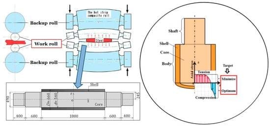
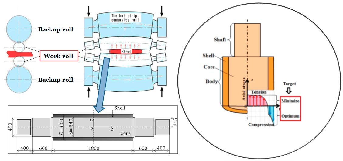
1. Introduction
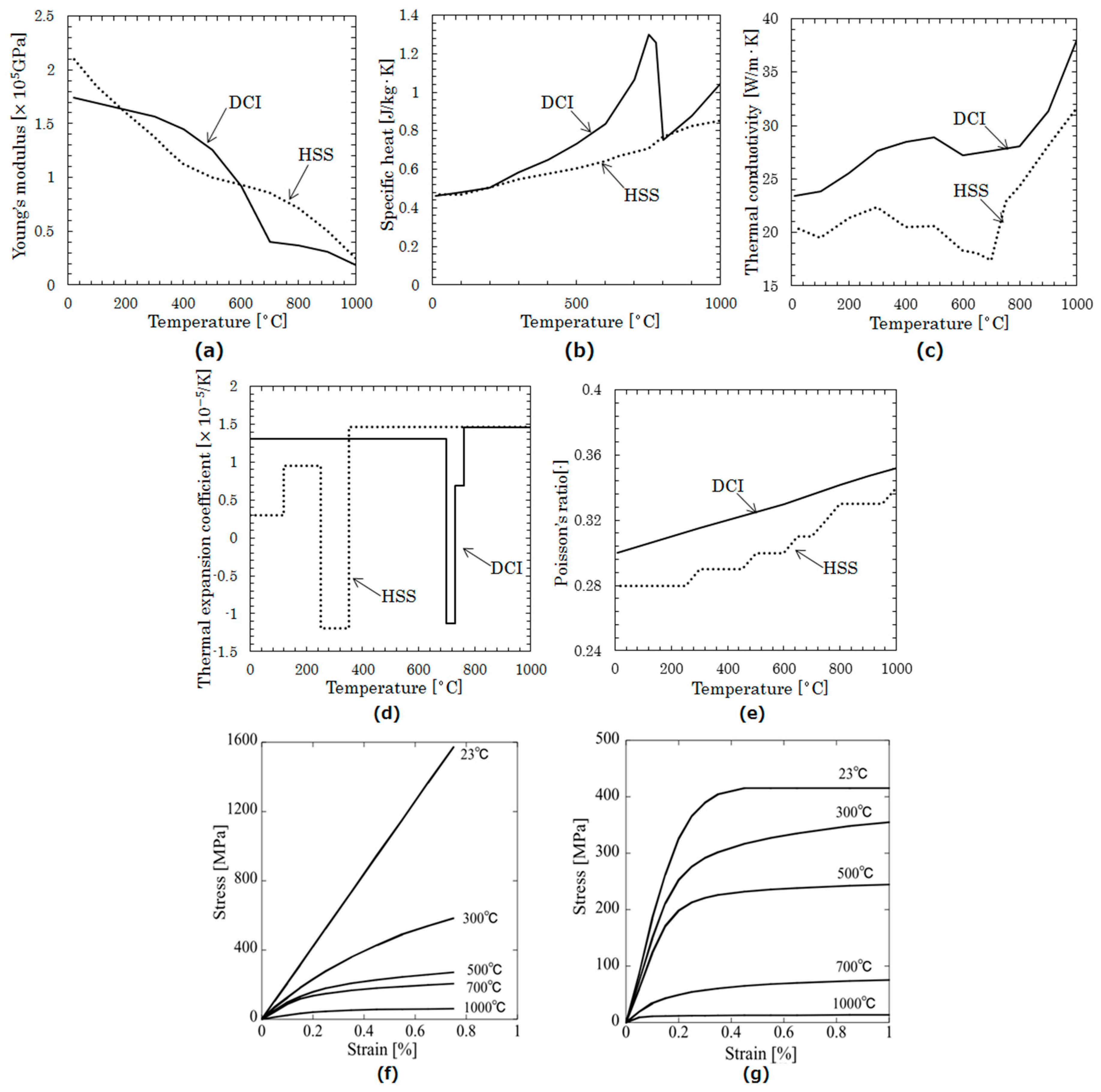
2. Mechanical Properties and Materials Data of Bimetallic Roll
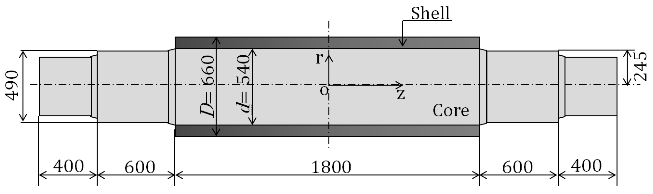
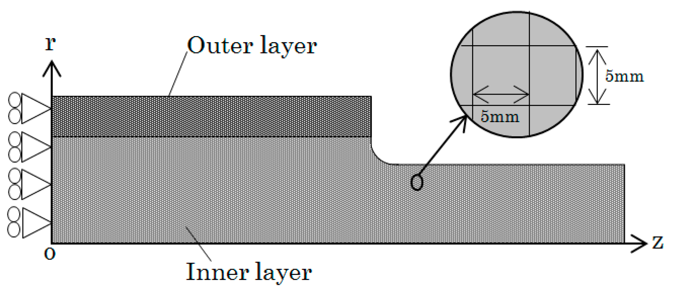
3. FEM Modeling
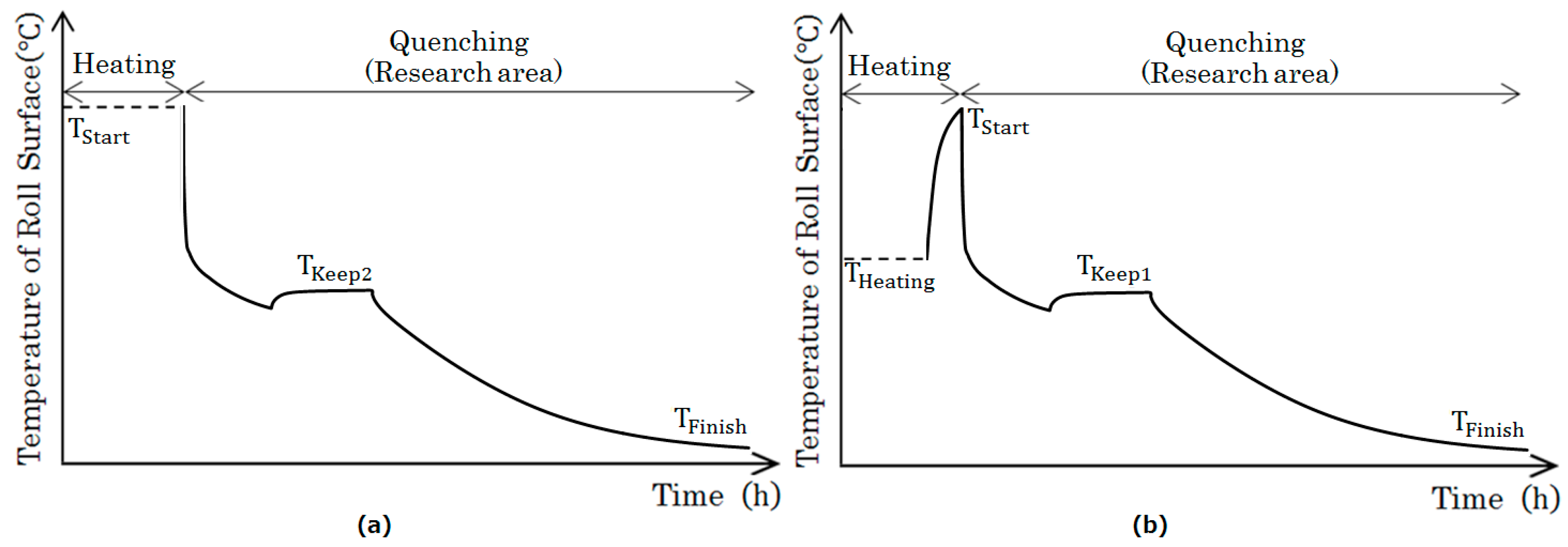
4. Influence on Residual Stress by Non-Uniform Heating
- The internal temperature is lower than 900 °C, which contributes to the avoidance of overheating and prevents material deterioration.
- Due to the rapid cooling of the quenching, a hard shell is obtained, improving the impact strength of the roll.
- Energy consumption can be reduced because the heating time is shortened.
- The time and cost of the operation can be also reduced since the time required for heating is shortened.
5. Comparison between Uniform Heating and Non-Uniform Heating
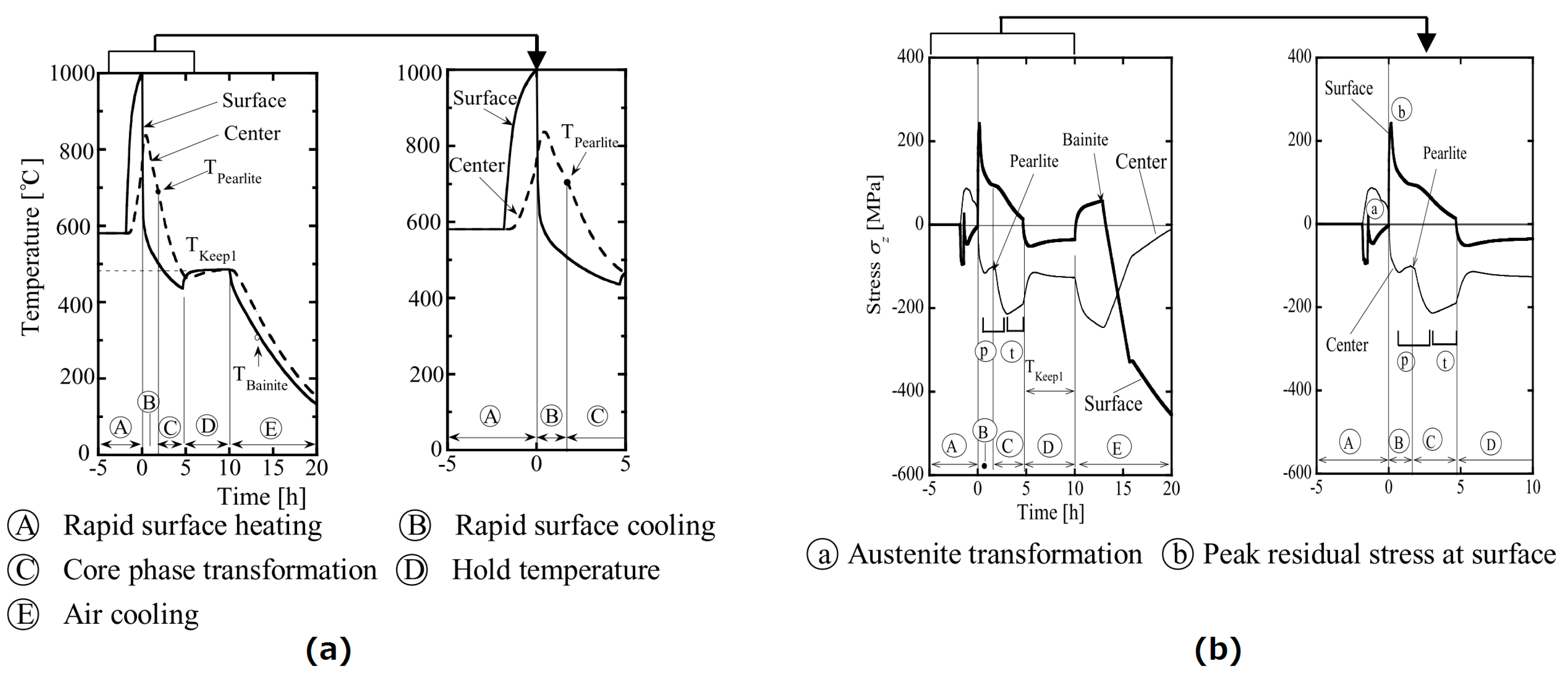
5.1. Stress Generation Mechanism of Uniform Heating and Non-Uniform Heating
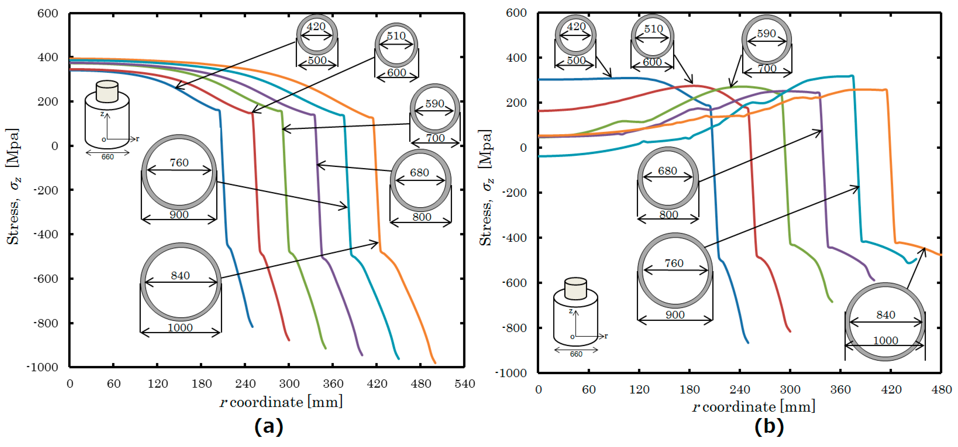
5.2. Effect of Diameter on Uniform Heating and Non-Uniform Heating
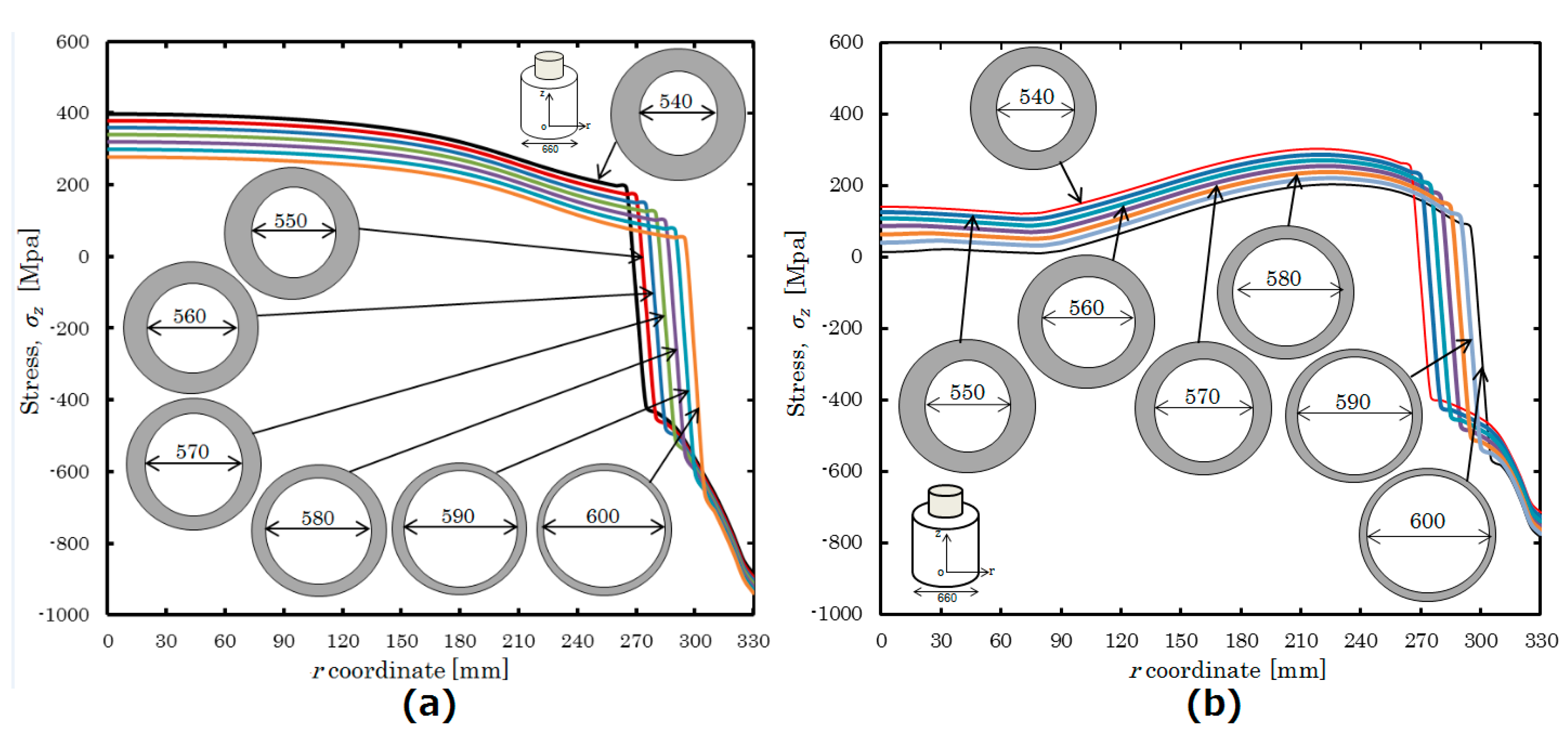
5.3. Effect of Area Ratio on Uniform Heating and Non-Uniform Heating
6. Conclusions
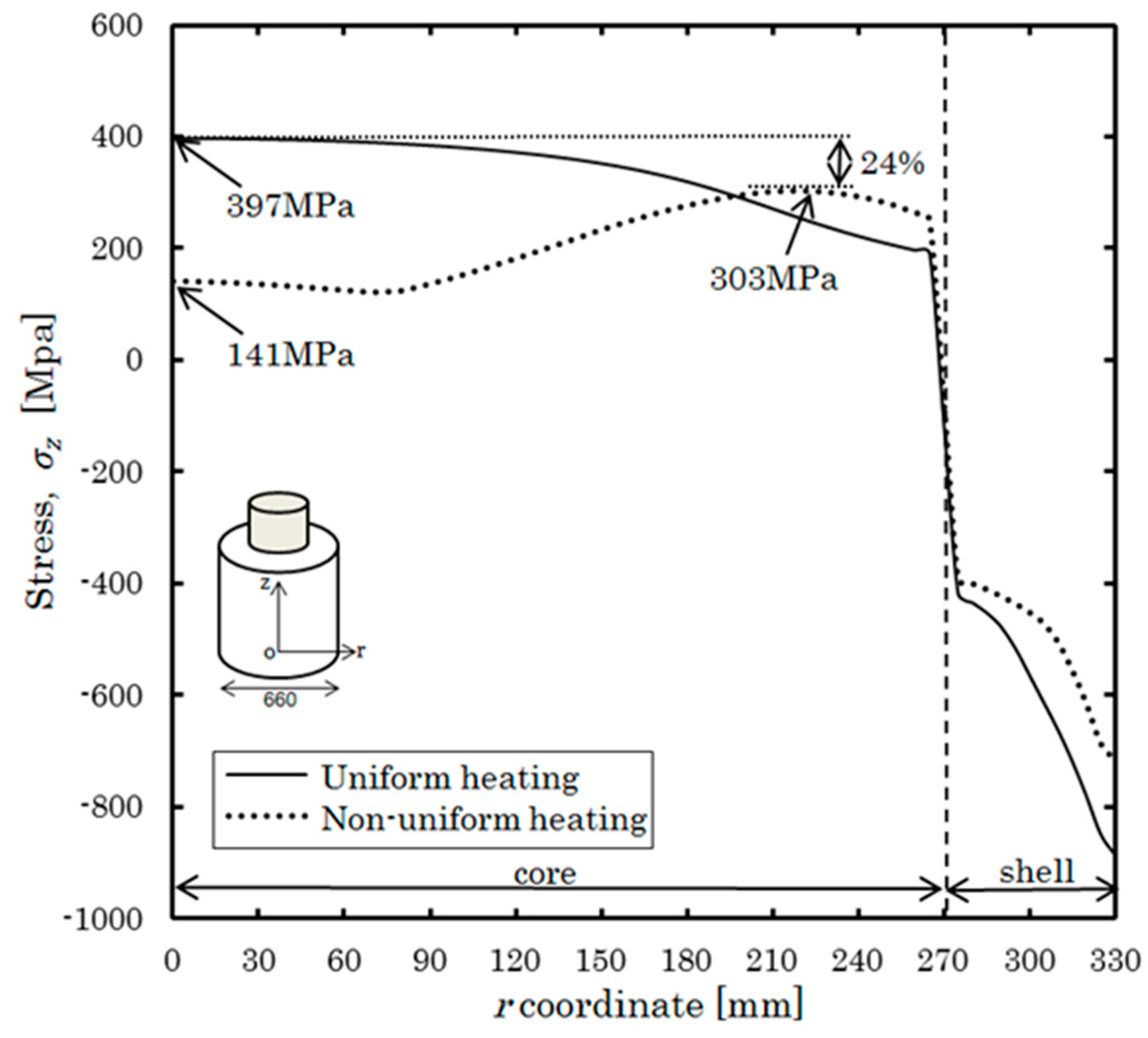
- The tensile stress of the inner layer after non-uniform heating and quenching was less than that obtained after uniform heating and quenching by 24%, while the compressive stress on the surface for both heating treatments did not differ greatly. As a result, the effect of preventing surface cracking can be expected to reduce damage originating from the center.
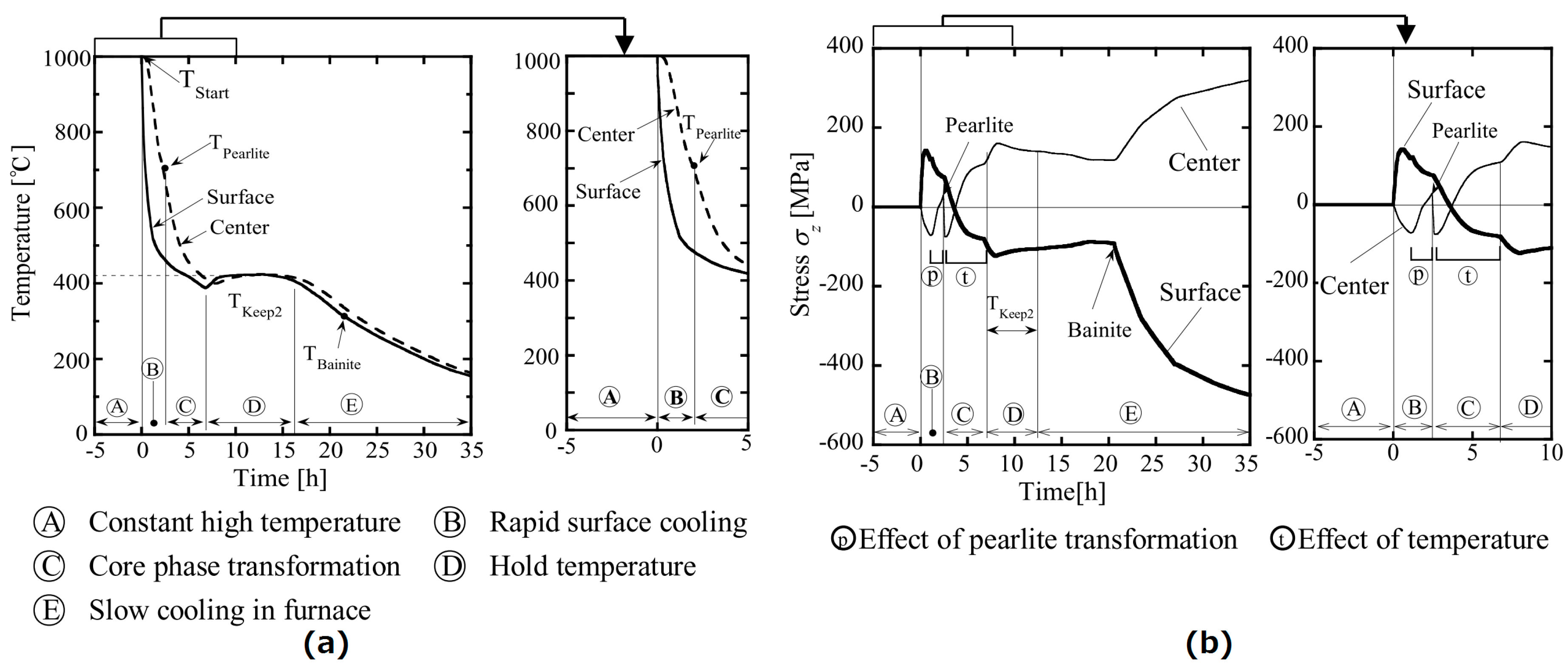
- Based on the stress generation mechanisms, it was found that the stress in the central part decreased by non-uniform heating because during pearlite transformation, Ⓑ, the increase in the central stress in non-uniform heating (ⓟ) was small. Similarly, the increase in the central stress (ⓣ) in non-uniform heating is also small in region Ⓒ after the pearlite transformation.
- Based on the diameter effect result, the center tensile stress for non-uniform heating was smaller compared to that for uniform heating. Furthermore, the surface compressive stress varied significantly as the diameter changes from 500 mm to 1000 mm.
- The results of the area ratio effect showed that the center tensile stress for non-uniform heating was smaller than that for uniform heating, while the compressive stress at the surface was almost unchanged for both results. In conclusion, the area ratio only exerts a small influence on the residual stress of bimetallic rolls for both heating treatments.
Author Contributions
Funding
Conflicts of Interest
References
- Goto, K.; Matsuda, Y.; Sakamoto, K.; Sugimoto, Y. Basic characteristics and microstructure of high-carbon high speed steel rolls for hot rolling mill. ISIJ Int. 1992, 32, 1184–1189. [Google Scholar] [CrossRef]
- Belzunce, F.J.; Ziadi, A.; Rodriguez, C. Structural integrity of hot strip mill rolling rolls. Eng. Fail. Anal. 2004, 11, 789–797. [Google Scholar] [CrossRef]
- Spuzic, S.; Strafford, K.N.; Subramanian, C.; Savage, G. Wear of hot rolling mill rolls: An overview. Wear 1994, 176, 261–271. [Google Scholar] [CrossRef]
- Park, J.W.; Lee, H.C.; Lee, S. Composition, microstructure, hardness, and wear properties of high-speed steel rolls. Metall. Mater. Trans. A 1999, 30, 399–409. [Google Scholar] [CrossRef]
- Sedlaček, M.; Podgornik, B.; Milanovič, S. A modified heat treatment to improve the properties of double layer cast rolls. Mater. Technol. 2014, 48, 983–990. [Google Scholar]
- Lee, J.H.; Oh, J.C.; Park, J.W.; Lee, H.C.; Lee, S. Effects of tempering temperature on wear resistance and surface roughness of a high speed steel roll. ISIJ Int. 2001, 41, 859–865. [Google Scholar] [CrossRef]
- Fu, H.; Xiao, Q.; Xing, J.D. A study on the crack control of a high-speed steel roll fabricated by a centrifugal casting technique. Mater. Sci. Eng. A 2008, 474, 82–87. [Google Scholar] [CrossRef]
- Noda, N.-A.; Hu, K.; Sano, Y.; Hosokawa, Y.; Wang, X. Accuracy of disk method to predict roll residual stress by measuring the sliced disk stress. ISIJ Int. 2017, 57, 1432–1440. [Google Scholar] [CrossRef]
- Li, C.S.; Yu, H.L.; Deng, G.Y.; Liu, X.H.; Wang, G.D. Numerical simulation of temperature field and thermal stress field of work roll during hot strip rolling. J. Iron Steel Res. Int. 2007, 14, 18–21. [Google Scholar] [CrossRef]
- Benasciutti, D.; Brusa, E.; Bazzaro, G. Finite elements prediction of thermal stresses in work roll of hot rolling mills. Procedia Eng. 2010, 2, 707–716. [Google Scholar] [CrossRef]
- Park, C.M.; Kim, W.S.; Park, G.J. Thermal analysis of the roll in the strip casting process. Mech. Res. Commun. 2003, 30, 297–310. [Google Scholar] [CrossRef]
- Sakai, K. Calculation of thermal stress in cylindrical steel during cooling. Tetsu-to-Hagane 1974, 60, 1591–1598. [Google Scholar] [CrossRef]
- Yin, Y.Z.; Wang, Y.Z. Numerical simulations of the effects of non-uniform temperature distributions on lateral torsional buckling resistance of steel I-beams. J. Constr. Steel Res. 2003, 59, 1009–1033. [Google Scholar] [CrossRef]
- Inoue, T.; Haraguchi, K.; Kimura, S. Stress analysis during quenching and tempering. J. Soc. Mater. Sci. Jpn. 1976, 25, 521–526. [Google Scholar] [CrossRef]
- Isomura, R. Residual stresses in heat-treated steels. Tetsu-to-Hagane 1961, 47, 936–950. [Google Scholar] [CrossRef]
- Acevedo, C.; Nussbaumer, A. Effect of tensile residual stresses on fatigue crack growth and S-N curves in tubular joints loaded in compression. Int. J. Fatigue 2012, 36, 171–180. [Google Scholar] [CrossRef]
- Noda, N.-A.; Hu, K.; Sano, Y.; Ono, K.; Hosokawa, Y. Residual stress simulation for hot strip bimetallic roll during quenching. Steel Res. Int. 2016, 87, 1478–1488. [Google Scholar] [CrossRef]
- Noda, N.-A.; Sano, Y.; Xu, W.; Nakagawa, Y.; Guan, W.; Ono, K.; Hu, K. Residual stress simulation and generation mechanism for hot strip composite roll during the quenching. Trans. Soc. Autom. Eng. Jpn. 2015, 46, 831–837. [Google Scholar]
- Noda, N.-A.; Hu, K.; Sano, Y.; Ono, K.; Hosokawa, Y. Usefulness of non-uniform heating and quenching method for residual stress of bimetallic roll: FEM simulation considering creep behavior. Steel Res. Int. 2017, 88, 1600165. [Google Scholar] [CrossRef]


| Property | Shell | Core |
|---|---|---|
| 0.2% proof stress (MPa) | 410 | |
| Young’s modulus (GPa) | 228 | 168 |
| Poisson’s ratio | 0.3 | 0.28 |
| Density (kg/m3) | 7600 | 7300 |
| Thermal expansion coefficient (K−1) | 12.6 × | 13.0 × |
| Thermal conductivity (W/m·K) | 20.2 | 23.4 |
| Specific heat (J/(kg·K) | 0.46 | 0.42 |
| Shore hardness (Hs) | 85 | 50 |
© 2018 by the authors. Licensee MDPI, Basel, Switzerland. This article is an open access article distributed under the terms and conditions of the Creative Commons Attribution (CC BY) license (http://creativecommons.org/licenses/by/4.0/).
Share and Cite
Noda, N.-A.; Sano, Y.; Aridi, M.R.; Tsuboi, K.; Oda, N. Residual Stress Differences between Uniform and Non-Uniform Heating Treatment of Bimetallic Roll: Effect of Creep Behavior on Residual Stress. Metals 2018, 8, 952. https://doi.org/10.3390/met8110952
Noda N-A, Sano Y, Aridi MR, Tsuboi K, Oda N. Residual Stress Differences between Uniform and Non-Uniform Heating Treatment of Bimetallic Roll: Effect of Creep Behavior on Residual Stress. Metals. 2018; 8(11):952. https://doi.org/10.3390/met8110952
Chicago/Turabian StyleNoda, Nao-Aki, Yoshikazu Sano, Mohd Radzi Aridi, Kenji Tsuboi, and Nozomu Oda. 2018. "Residual Stress Differences between Uniform and Non-Uniform Heating Treatment of Bimetallic Roll: Effect of Creep Behavior on Residual Stress" Metals 8, no. 11: 952. https://doi.org/10.3390/met8110952
APA StyleNoda, N.-A., Sano, Y., Aridi, M. R., Tsuboi, K., & Oda, N. (2018). Residual Stress Differences between Uniform and Non-Uniform Heating Treatment of Bimetallic Roll: Effect of Creep Behavior on Residual Stress. Metals, 8(11), 952. https://doi.org/10.3390/met8110952