Article

Microstructure and Tensile Property of the Joint of Laser-MIG Hybrid Welded Thick-Section TC4 Alloy

State Key Laboratory of Advanced Welding and Joining, Harbin Institute of Technology, Harbin 150001, China
*
Author to whom correspondence should be addressed.
Metals 2018, 8(12), 1002; https://doi.org/10.3390/met8121002
Submission received: 19 October 2018 / Revised: 13 November 2018 / Accepted: 22 November 2018 / Published: 1 December 2018

Abstract

:
In this paper, thick-section TC4 alloy was welded to itself by laser-MIG hybrid (LAMIG) welding. The microstructure of the welded joints was characterized by scanning electron microscopy (SEM) and transmission electron microscopy (TEM). The results revealed that α’ and β phases were formed in the weld seam. The effects of heat input (E) on the microstructure and tensile strength of the joints were investigated. With the increase of heat input, the residence time of platelet α’ martensite in the high-temperature phase changing zone became longer and the thickness of platelet α’ martensite increased. Furthermore, the β thickness became large, and tangling dislocations were found to exist in platelet α’. In addition, the increasing heat input could cause a decrease in the tensile strength. The failed dimple pattern experienced a change from equiaxed to tearing, which was harmful to the property of the joint.

1. Introduction

Titanium alloys have become important structural materials in the aerospace industry due to their excellent comprehensive properties such as low density, perfect thermal stability, and high corrosion resistance [1,2,3]. Among these titanium alloys, thick-section TC4 alloy is extensively used in industry. To achieve practical applications, thick-section TC4 alloy is required to be welded together to fabricate complex structures.
The research on the joining of TC4 alloy has been well reported, such as tungsten inert-gas welding (TIG) [4,5,6], metal inert-gas welding (MIG) [7], electron beam welding [8,9,10,11], laser beam welding [12,13,14], and laser-MIG hybrid (LAMIG) welding [15,16]. Among these welding techniques, LAMIG welding is suitable for the joining of TC4 alloy. LAMIG welding, combining laser beam welding and arc welding, has been proven to be able to effectively resolve the disadvantages of laser beam welding, such as insufficient gap bridging ability and required precision on positioning. The interaction of laser and MIG arcs results in a good welding stability, high energy density, and large heat input area [17]. Recently, some studies on the LAMIG welding of thin-plate titanium alloy have been reported. Brandizzi et al. [18] joined TC4 alloy with a thickness of 3 mm using LAMIG welding, and the results indicated that the joints produced by LAMIG welding exhibited higher mechanical properties and lower deformation compared with the joints welded by conventional laser beam welding. Li et al. [19] reported the LAMIG welding of Ti-Al-Zr-Fe alloy with a thickness of 4 mm. The relationship between the tensile properties and the microstructure was analyzed. The best welded joints could be achieved due to the improvement of the joint microstructure. In addition, some studies on the welding of titanium and other alloys have been reported. Oliveira et al. [20] used pulsed laser to join NiTi and Ti6Al4V with the help of a Niobium interlayer. Defect-free joints were produced that matched the ultimate tensile strength of the Niobium interlayer. Zhang et al. [21] analyzed the microstructure and mechanical properties of laser-TIG hybrid welded Ti-22Al-27Nb/TA15 joints. The microstructure evolution of heat-affected zone (HAZ) and fusion zone (FZ) was investigated. Tensile tests at room temperature and 650 °C were conducted to evaluate the mechanical properties of the hybrid welded joints.
Unfortunately, the above investigations mainly focused on the laser-MIG hybrid welding of thin-plate titanium alloys. Only a few works have investigated the LAMIG welding of thick-section TC4 alloy. Multilayer welding is usually preferred for the LAMIG welding of thick-section TC4 alloy. During the multilayer welding process, the temperature of the layers is high due to the relatively high heat input. As we know, the microstructure of the welded joints is sensitive to the temperature variation, which absolutely affects the mechanical properties of the joints. However, the effects of heat input and layer temperature on the microstructure and mechanical properties are rarely reported.
In this study, thick-section TC4 alloy was successfully welded by double-sided LAMIG welding. The microstructure and mechanical properties of the joints under different heat inputs were investigated comprehensively.

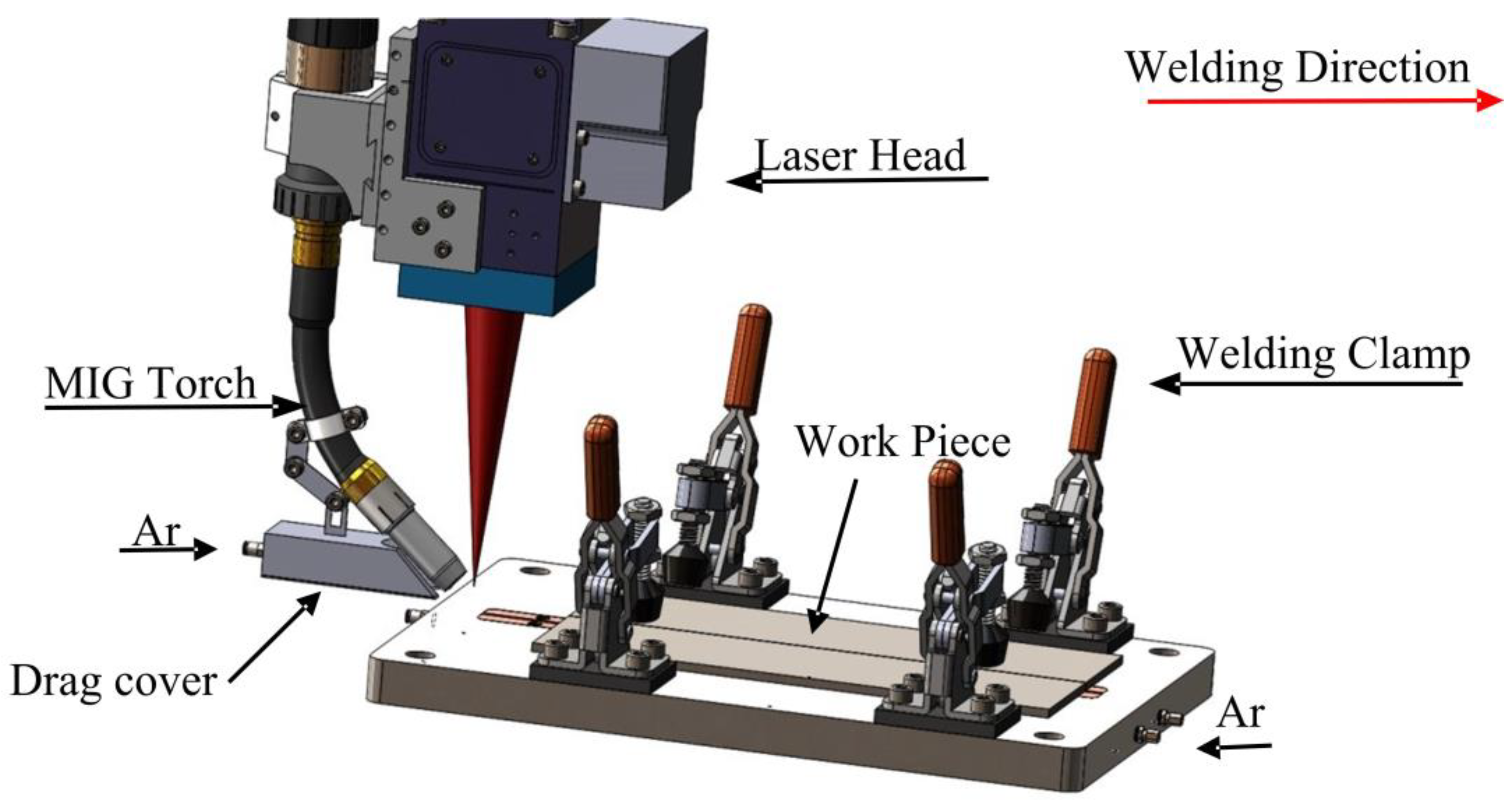
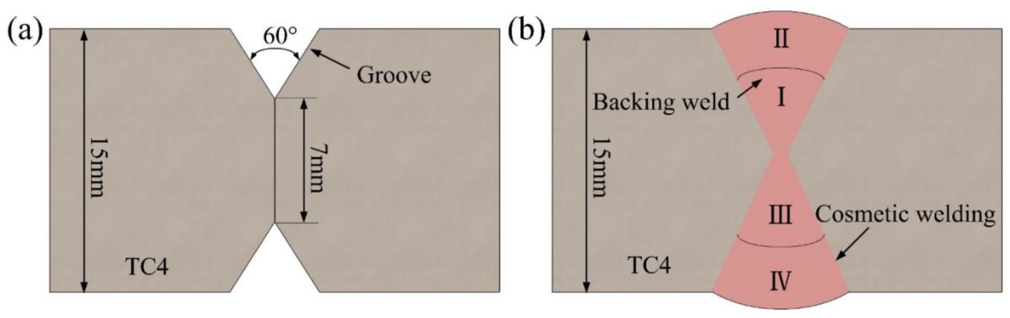
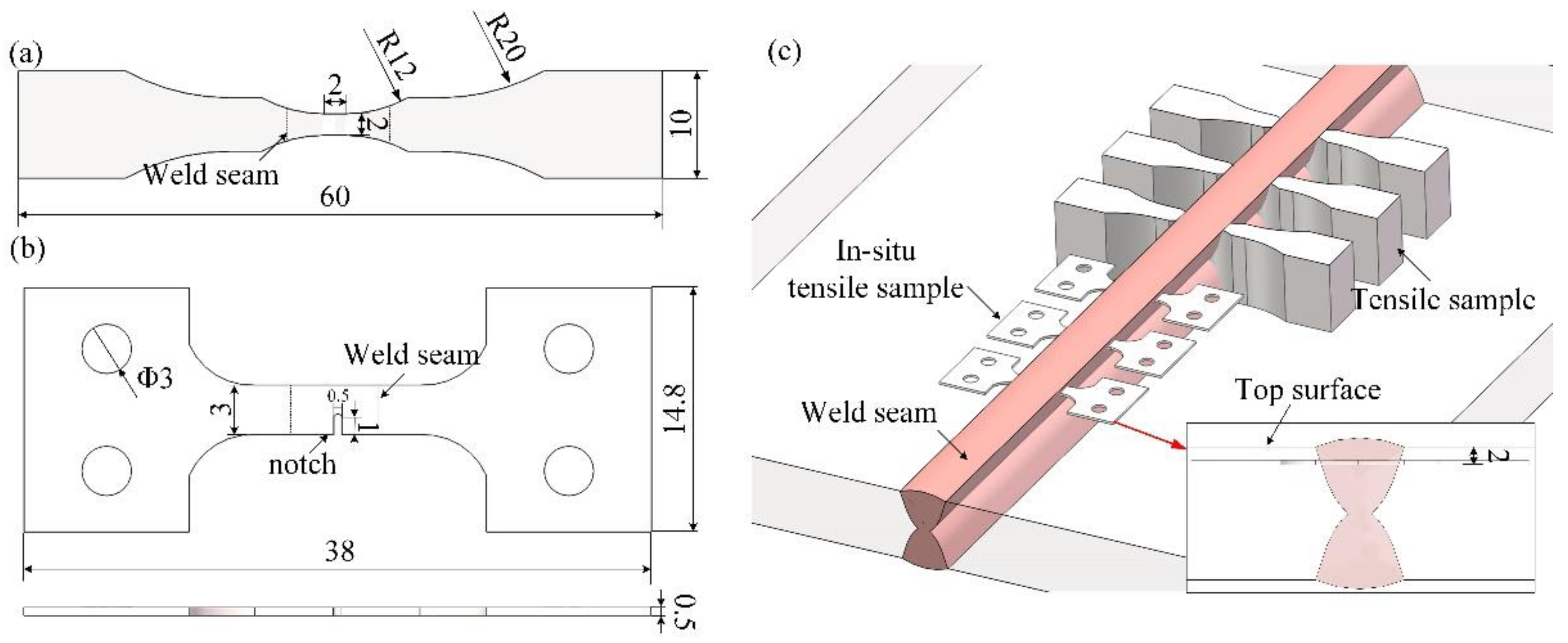
2. Materials and Methods

The base material used in this study was thick-section TC4 alloy with dimensions of 15 × 200 × 80 mm. TC4 standard welding wire ERTi-6Al-4V with a diameter of 1.2 mm was chosen as the filler material. The microstructure of thick-section TC4 alloy is displayed in Figure 1. It was clear that the microstructure of the employed TC4 alloy primarily consisted of equiaxed primary α phase and plate-shaped α + β phases. The chemical compositions and physical properties at room temperature of TC4 alloy are listed in Table 1 and Table 2, respectively.
An fiber laser (YLR-10000, IPG Photonics, Burbach, Germany) system (wavelength 1060 nm, spot size 0.26 mm, spatial profile “Gaussian distribution”) with a maximum power of 10 kW and a MIG welding (TPS4000, Fronius, Austria) system were used for the welding experiments. Figure 2 illustrates a schematic diagram of the laser-MIG hybrid welding experimental equipment. The laser focus position was in front of the trailing MIG arc. The angle between the axis of the laser beam and the welding wire was approximately 50°. The laser-MIG arc distance (DLA) was in the range of 2 to 4 mm. During welding, 99.999% pure argon gas was adopted to protect the molten pool from oxidation. Moreover, the back shielding gas behind the molten pool was also used to protect the just-solidified weld seam. The double-V shape grooves were machined from the base materials, and a four-layer welding process was adopted. The geometric dimension drawing of the LAMIG-welded TC4 joint is shown in Figure 3a. Figure 3b shows the schematic diagram of the welding sequence and distribution of welding passes, where I and III are the weld seam of a backing weld, and II and IV are the weld seam of a cosmetic weld. The parameters of the backing weld are listed as shown in Table 3, and the five types of the parameters of cosmetic weld are listed as shown in Table 4. The backing weld was carried out with fixed welding parameters.
Figure 4a shows the shape and size of the non-standard butt joint tensile sample for the tensile test. Since the strength of the titanium alloy welded joint is greater than that of the base material, the tensile strength of the obtained weld seam cannot be measured through by the standard joint form. This purpose of this paper was to analyze the changes in the microstructure and properties of the weld seam under different heat input, so this non-standard tensile specimen was selected. Three samples were tested for each condition using an electromechanical testing machine (Instron plus 50 kN) and a test speed of 0.1 mm/min. In addition, in-situ tensile equipment (MICROTEST2000, Gatan, Pleasanton, CA, USA) was adopted to investigate the effect of the microstructure on crack propagation. Figure 4b shows the shape and size of the in-situ tensile sample according to international standard EN ISO 6892.1-2009. The schematic diagram and distribution of tensile samples are shown in Figure 4c. The in situ test samples were obtained within the interior of the weld seam, which were located at a 2-mm depth from the top surface. As the tensile property of the weld seam was quite high, a notch was cut in the bottom of the weld seam to ensure the process of the in situ tensile test. The microstructure and fracture surface of the joints were analyzed using a scanning electron microscope (Quanta 200FEG, FEI, Hillsboro, OR, USA). Moreover, the morphology and diffraction patterns of the phases were characterized by transmission electron microscope (Tecnai G2 F30, FEI, Hillsboro, OR, USA).

3. Results and Discussion

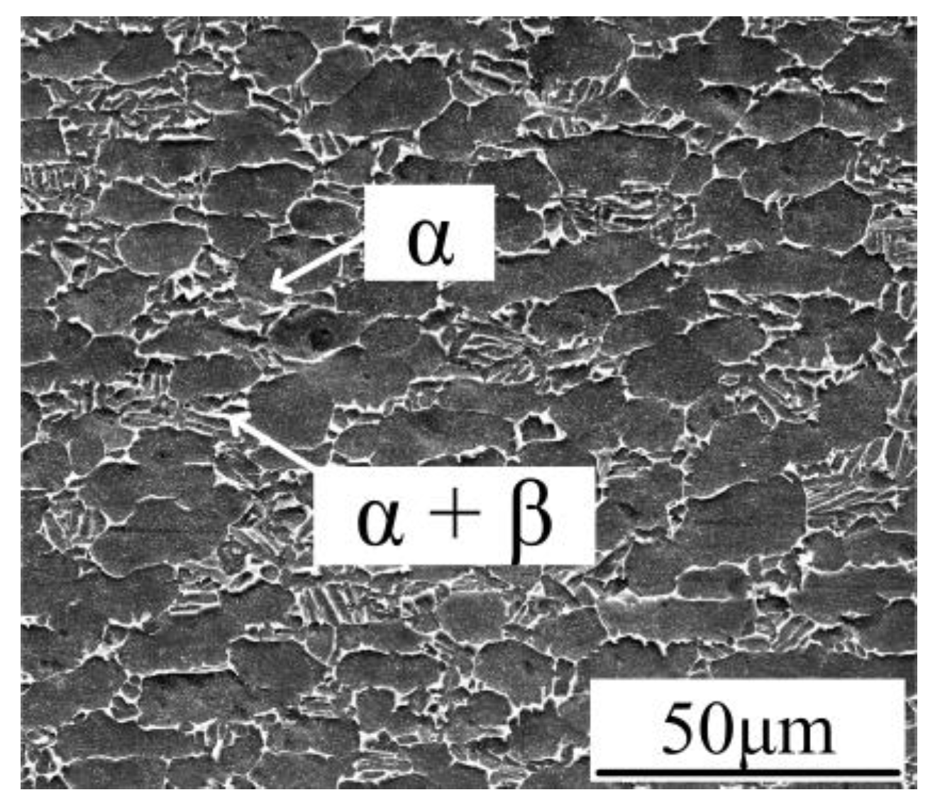
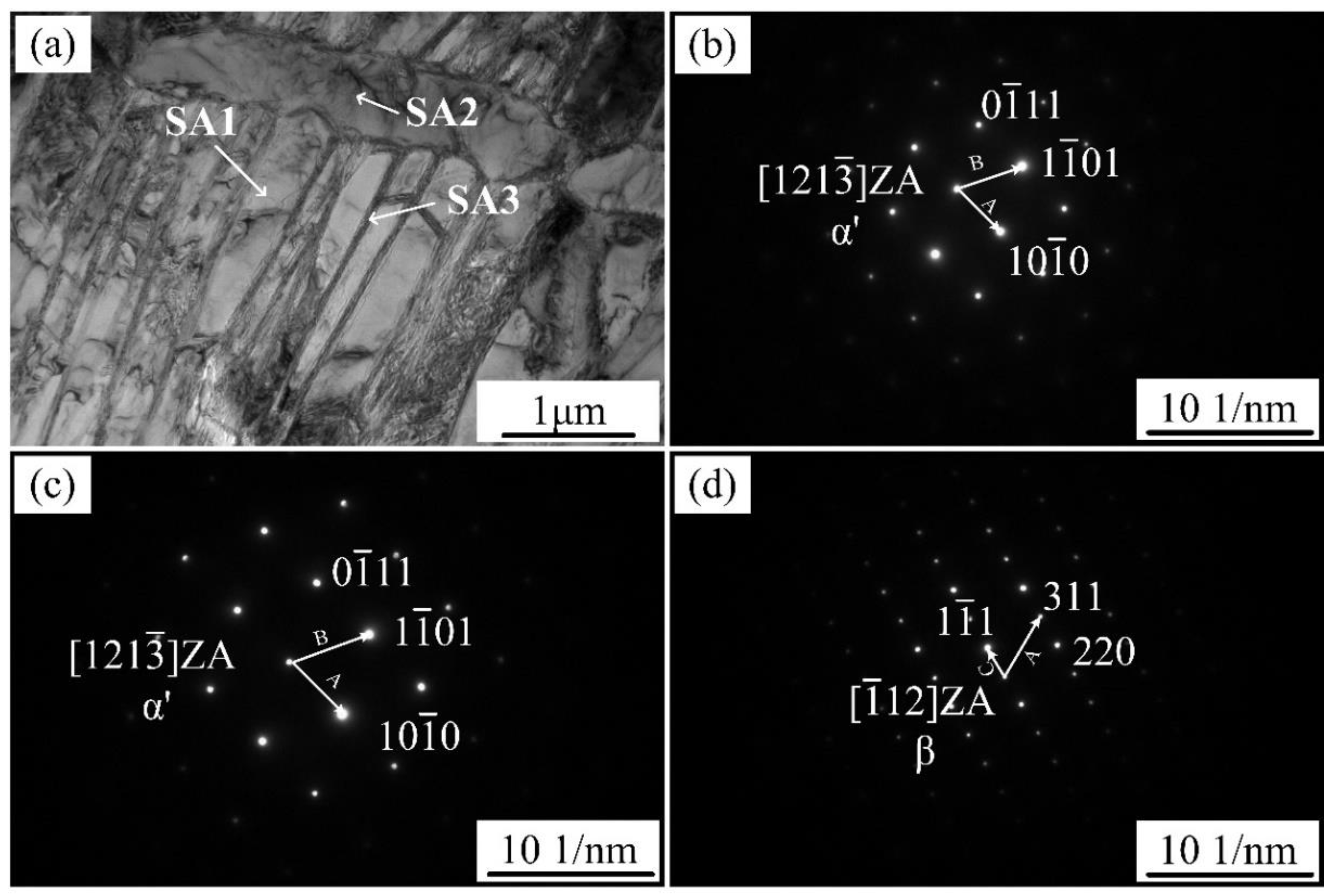
3.1. Microstructure Analysis

Figure 5a shows cross section macrographs of the LAMIG-welded joint. It is clear that the weld seam presented a dumbbell shape, and weld defects such as undercut and large pores were not observed. The detailed microstructure of the cosmetic weld (marked as A) is shown in Figure 5b. It can be seen from Figure 5b that coarsening acicular α’ phase traversed the grain to form a basket-like Widmanstätten structure. Figure 5c presents a high magnification image of the microstructure of the backing weld (labeled as B). Obviously, only a tiny acicular α’ phase existed in this zone. During the laser welding process, a smaller heat input was contained in the backing weld zone, being smaller than that in the cosmetic weld zone. Therefore, the grain size of the cosmetic weld zone was much larger than that of the backing weld zone.
TEM analysis was conducted to further analyze the microstructure of the cosmetic weld zone (marked as A), the results of which are displayed in Figure 6. The corresponding selected area electron diffractions (SAEDs) confirmed that the bright white phase corresponded to the α’ martensite phase (PDF: 51-0631) and the dark phase distributed in the martensite plates was the residual β phase (PDF: 88-2321) with a body-centered cubic structure. In addition, the martensite phases in the weld seam exhibited acicular and platelet morphologies. Therefore, the microstructure of the weld seam was composed of α’ and β phases, which was in agreement with the research results obtained by Mazumder et al. [22].

3.2. Effect of Heat Input on the Microstructure of the Weld Seam

Uygur et al. [23] suggested that metal materials usually preferred to fracture at the coarse grain structure in the weld seam. As mentioned in Section 3.1, the grain size of the cosmetic weld zone was much larger than that of the backing weld zone. The microstructure of the cosmetic weld zone could affect the mechanical properties of the joints significantly. The microstructure and tensile strength of the joints welded at different heat inputs were investigated. TEM bright-field images of the microstructure of the cosmetic weld zone welded at heat inputs from 2.2 × 10³ J/cm to 5.5 × 10³ J/cm are shown in Figure 7. It could be observed that with the increase of heat input, the thickness of platelet α’ martensite increased correspondingly, and the martensite became arranged parallel to each other. Higher heat input resulted in a longer duration of time above the α-β transformation temperature. During the cooling process, the β phase precipitated first and then grew to form a coarse-grained structure. When further decreasing the temperature below the Ms point, primary α’ martensite preferentially nucleated in the original β grain boundary [24]. Due to the low cooling rate, primary α’ martensite grew sharply with a coarse-grained morphology to form paralleled and regular platelet α’ martensite. Finally, cluster-shaped lath martensite was formed in the weld seam.
With the increase of the thickness of the platelet α’ martensite, the dislocation density and β phase distributed in the martensite plates were correspondingly changed. As the heat input increased, the thickness of the β phase increased. Additionally, a large number of tangled dislocations were formed in platelet α’, as shown in Figure 6c. The martensitic transformation was mainly achieved by the dislocation generation and movement in the grain boundary or intra-crystalline movement, which was accompanied by stress generation and release. When the heat input was low, the transition stress in the α′ martensite nucleation and growth was small and the dislocation density was also low. As the heat input increased, the formation of a large number of α′ martensite clusters caused large phase transition stress and a high dislocation density.

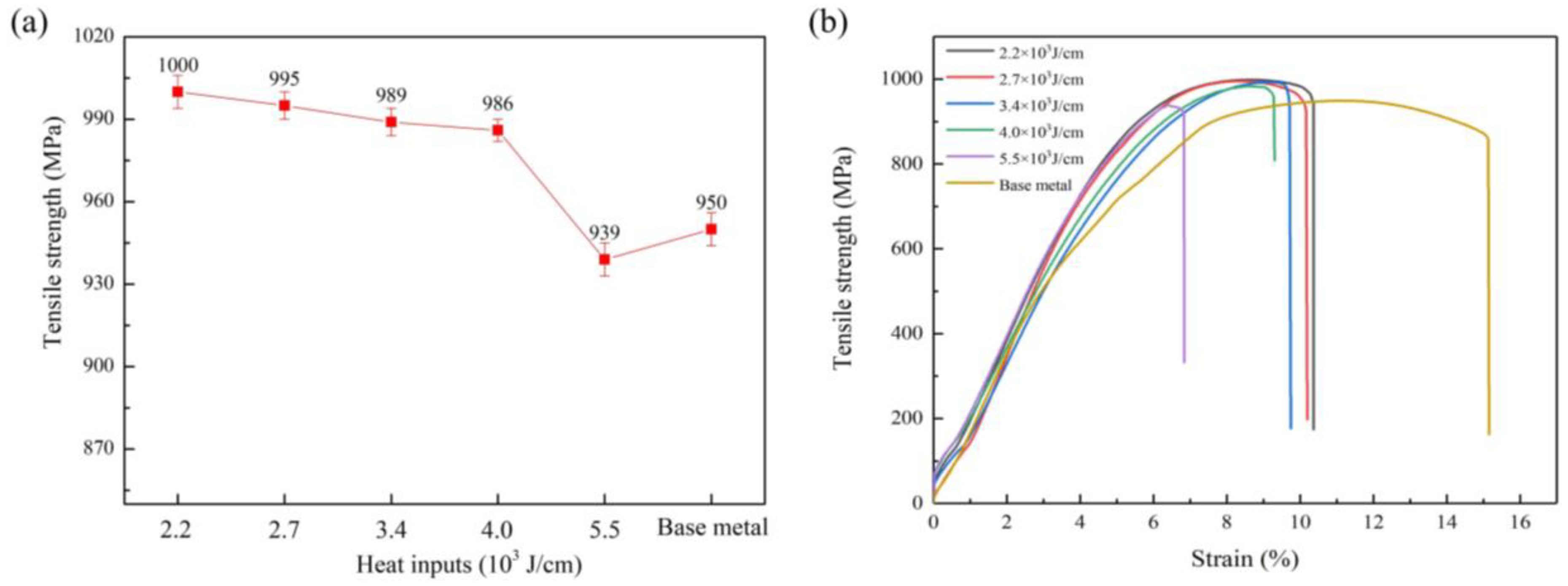
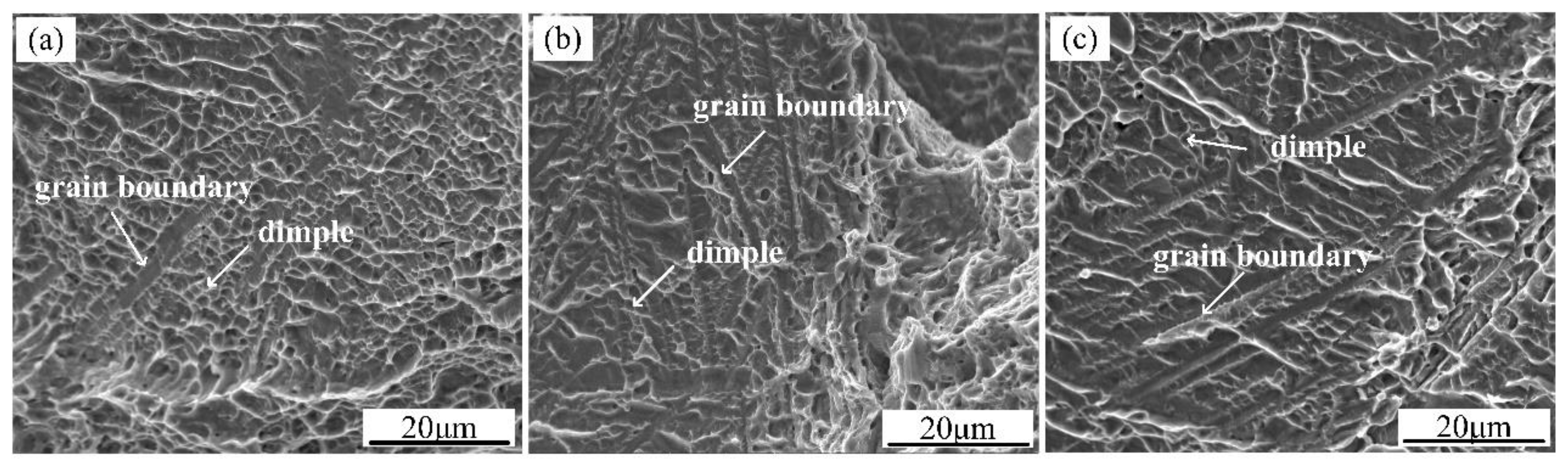
3.3. Mechanical Performance

According to the above analysis, different heat inputs resulted in various morphologies of platelet α′martensite, β phase, and dislocation. Meanwhile, the morphologies of platelet α′ martensite and β phase had a significant effect on the tensile strength of the joints. The tensile strength of the joints welded at different heat inputs is depicted in Figure 8a. For comparison, the tensile strength of the base material is also given in Figure 8a. It can be concluded that the tensile strength of the joints was decreased obviously with increasing heat input. When the heat input reached 5.5 × 10³ J/cm, the tensile strength of the joint was even lower than that of the base material. Figure 8b illustrates room-temperature strain-stress curves of weld seam prepared with different heat inputs. The strain of the six curves was quite different, and the lower heat input always led to a higher strain of the joints.
To identify the fracture path and the relationship between microstructure and mechanical properties, an in situ tensile test was conducted and the results are discussed below. Figure 9 illustrates low-magnification images of the fracture propagation path of the joints produced at different heat inputs. When the heat input was 2.2 × 10³ J/cm, the fracture propagated in a straight line perpendicular to the tensile direction. With the increase of the heat input, the fracture path became serrated and irregular, as shown in Figure 9b,c.
Figure 10 displays SEM images of the fracture surfaces at low magnification. As shown in Figure 10a, a large number of uniform dimples were observed, indicating that the fracture morphology had the characteristic of ductile fracture. However, when the heat inputs were high, many stripe-like planes were presented, as shown in Figure 10b,c. High-magnification SEM images of the fracture patterns are illustrated in Figure 11. Obviously, the morphologies of the dimples significantly changed with the increase of heat input. Under low heat input, shown in Figure 11a, the fracture surface dimples belonged to stretch and equiaxial types. As the heat input increased, the fracture surface exhibited stretch and tearing elongation-type dimples. The above fracture morphologies were also researched by Matsumoto et al. [25]. It can be concluded that when there is relatively high heat input, the main fracture mode involves microcracks that form at the crystal boundary under exogenic action, and visible microvoids are generated by the aggregation of adjacent microcracks. Subsequently, the microvoids grow, proliferate, and finally connect to each other to form a fracture.
According to above analysis, the high heat input was beneficial to the crack propagation in the weld seam. The reasons for this result are listed as follows. The higher heat input leads to a higher grain size and consequently a lower number of grain boundaries; these can give rise to crack propagation, which is consequently easier to achieve in higher heat input samples [26,27]. In addition, the β phase distributed in α’ martensite plates possessed plastic deformation, resulting in high tensile strength. A high dislocation density was detrimental to intra-crystalline crack propagation. Therefore, cracks were more likely to start and expand along the grain boundary.

4. Conclusions

Based on the above experimental analysis, the following conclusions were drawn:
(1) The microstructure of the weld seam was characterized by TEM analysis and the results indicated that the weld seam mainly consisted of α’ martensite and β phases. The grain size of the cosmetic weld zone was much larger than that of the backing weld zone due to the different cooling rates.
(2) With the increase of heat input, the morphology of α′ martensite transformed from an acicular shape at low heat input to a platelet-like shape at high heat input. Large grains, thick β phase, and high dislocation density allowed cracks to form more easily and expand along the grain boundary during the tensile testing.
(3) As the heat input increased, the fracture surfaces changed from stretch- and equiaxial-type dimples under low heat input to stretch and tearing elongation-type dimples under high heat input. Therefore, low heat input was selected for the LAMIG welding of thick-section TC4 alloy.

Author Contributions

Conceptualization, Y.C. and W.T.; Methodology, X.S. and J.F.; Formal Analysis, X.S.; Investigation, W.T.; Resources, Y.C.; Data Curation, X.S. and J.F.; Writing—Original Draft Preparation, Y.C.; Writing—Review and Editing, Y.C. and X.S.; Visualization, W.T.; Supervision, X.S. and J.F.; Project Administration, W.T.

Funding

This research received no external funding.

Acknowledgments

We thank Ze Tian, Meng Jiang, and Yunlong Zhang for all the guidance and support given throughout this research work.

Conflicts of Interest

The authors declare no conflict of interest.

References

  1. Guo, P.; Zhao, Y.; Zeng, W.; Hong, Q. The effect of microstructure on the mechanical properties of TC4-DT titanium alloys. Mater. Sci. Eng. A 2013, 563, 106–111. [Google Scholar] [CrossRef]
  2. Yung, W.K.; Ralph, B.; Lee, W.B.; Fenn, R. An investigation into welding parameters affecting the tensile properties of titanium welds. J. Mater. Process. Technol. 1997, 63, 759–764. [Google Scholar] [CrossRef]
  3. Gursel, A. Crack risk in Nd: YAG laser welding of Ti-6Al-4V alloy. Mater. Lett. 2017, 197, 233–235. [Google Scholar] [CrossRef]
  4. Junaid, M.; Baig, M.N.; Shamir, M.; Khan, F.N.; Rehman, K.; Haider, J. A comparative study of pulsed laser and pulsed TIG welding of Ti-5Al-2.5Sn titanium alloy sheet. J. Mater. Process. Tech. 2017, 242, 24–38. [Google Scholar] [CrossRef]
  5. Badheka, V.J.; Basu, R.; Omale, J.; Szpunar, J. Microstructural aspects of TIG and A-TIG welding process of dissimilar steel grades and correlation to mechanical behavior. Trans. Indian Inst. Met. 2016, 69, 1765–1773. [Google Scholar] [CrossRef]
  6. Júnior, P.C.S.; Resende, N.V.; Rodrigues, M.A.; Soares, C.J.; Raposo, L.H.A. Effect of joint design and welding type on the flexural strength and weld penetration of Ti-6Al-4V alloy bars. J. Prosthet. Dent. 2015, 113, 467–474. [Google Scholar] [CrossRef] [PubMed]
  7. Zhang, Y.M.; Li, P.J. Modified active control of metal transfer and pulsed GMAW of titanium. Weld. J. 2001, 80, 54–70. [Google Scholar]
  8. Liu, P.; Zhang, G.M.; Zhai, T.; Feng, K.Y. Effect of treatment in weld surface on fatigue and fracture behavior of titanium alloys welded joints by vacuum electron beam welding. Vacuum 2017, 141, 176–180. [Google Scholar] [CrossRef]
  9. Gao, F.; Gao, Q.; Jiang, P.; Liu, Z.; Liao, Z. Microstructure and properties of titanium alloy electron beam weldments based on the different heat input conditions of the same line energy. Vacuum 2017, 146, 136–141. [Google Scholar] [CrossRef]
  10. Edwards, P.D.; Ramulu, M. Comparative study of fatigue and fracture in friction stir and electron beam welds of 24 mm thick titanium alloy Ti-6Al-4V. Fatigue Fract. Eng. Mater. Struct. 2016, 39, 1226–1240. [Google Scholar] [CrossRef]
  11. Yang, X.; Li, S.; Qi, H. Ti-6Al-4V welded joints via electron beam welding: Microstructure, fatigue properties, and fracture behavior. Mater. Sci. Eng. A 2014, 597, 225–231. [Google Scholar] [CrossRef]
  12. Ferreira, N.A.; Senna, P.M.; Lago, D.; Senna, L.F.; Sampaio-Filho, H.R. Influence of stress corrosion on the mechanical properties of laser-welded titanium. J. Prosthet. Dent. 2016, 115, 356–362. [Google Scholar] [CrossRef] [PubMed]
  13. Panwisawas, C.; Perumal, B.; Ward, R.M.; Turner, N.; Turner, R.P.; Brooks, J.W.; Basoalto, H.C. Keyhole formation and thermal fluid flow-induced porosity during laser fusion welding in titanium alloys: Experimental and modelling. Acta Mater. 2017, 126, 251–263. [Google Scholar] [CrossRef]
  14. Akman, E.; Demir, A.; Canel, T.; Sinmazcelik, T. Laser welding of Ti6Al4V titanium alloys. J. Mater. Process. Tech. 2009, 209, 3705–3713. [Google Scholar] [CrossRef]
  15. Gao, M.; Chen, C.; Wang, L.; Wang, Z.; Zeng, X. Laser-arc hybrid welding of dissimilar titanium alloy and stainless steel using copper wire. Metall. Mater. Trans. A 2015, 46, 2007–2020. [Google Scholar] [CrossRef]
  16. Chen, Y.; Feng, J.; Li, L.; Chang, S.; Ma, G. Microstructure and mechanical properties of a thick-section high-strength steel welded joint by novel double-sided hybrid fibre laser-arc welding. Mater. Sci. Eng. A 2013, 582, 284–293. [Google Scholar] [CrossRef]
  17. Ribic, B.; Palmer, T.A.; DebRoy, T. Problems and issues in laser-arc hybrid welding. Int. Mater. Rev. 2009, 54, 223–244. [Google Scholar] [CrossRef]
  18. Brandizzi, M.; Satriano, A.A.; Sorgente, D.; Tricarico, L. Laser-arc hybrid welding of Ti6Al4V titanium alloy: mechanical characterization of joints and gap tolerance. Weld. Int. 2013, 27, 113–120. [Google Scholar] [CrossRef]
  19. Li, R.; Li, Z.; Zhu, Y.; Rong, L. A comparative study of laser beam welding and laser-MIG hybrid welding of Ti-Al-Zr-Fe titanium alloy. Mater. Sci. Eng. A 2011, 528, 1138–1142. [Google Scholar] [CrossRef]
  20. Oliveira, J.P.; Panton, B.; Zeng, Z.; Andrei, C.M.; Zhou, Y.; Miranda, R.M.; Braz Fernandes, F.M. Laser joining of NiTi to Ti6Al4V using a Niobium interlayer. Acta Mater. 2016, 105, 9–15. [Google Scholar] [CrossRef]
  21. Zhang, K.Z.; Lei, Z.L.; Chen, Y.B.; Liu, M.; Liu, Y. Microstructure characteristics and mechanical properties of laser-TIG hybrid welded dissimilar joints of Ti-22Al-27Nb and TA15. Opt. Laser. Technol. 2015, 73, 139–145. [Google Scholar] [CrossRef]
  22. Mazumder, J.; Steen, W.M. Microstructure and Mechanical Properties of Laser Welded Titanium 6Al-4V. Metall. Mater. Trans. A 1982, 13, 865–871. [Google Scholar] [CrossRef]
  23. Uygur, I.; Dogan, I. The effect of TIG welding on microstructure and mechanical properties of a butt-joined-unalloyed titanium. Metalurgija 2005, 44, 119–123. [Google Scholar]
  24. Moiseev, V.N. The martensitic transformation during deformation of titanium alloys with metastable β phase. Met. Sci. Heat Treat. 1972, 14, 391–395. [Google Scholar] [CrossRef]
  25. Matsumoto, H.; Yoneda, H.; Sato, K.; Kurosu, S.; Maire, E.; Fabregue, D.; Konno, T.J.; Chiba, A. Room-temperature ductility of Ti-6Al-4V alloy with α′ martensite microstructure. Mater. Sci. Eng. A 2011, 528, 1512–1520. [Google Scholar] [CrossRef]
  26. Lehto, P.; Remes, H.; Saukkonen, T.; Hänninen, H.; Romanoff, J. Influence of grain size distribution on the Hall-Petch relationship of welded structural steel. Mater. Sci. Eng. A 2014, 592, 28–39. [Google Scholar] [CrossRef]
  27. Oliveira, J.P.; Zeng, Z.; Omori, T.; Miranda, R.M.; Braz Fernandes, F.M. Improvement of damping properties in laser processed superelastic Cu-Al-Mn shape memory alloys. Mater. Design 2016, 98, 280–284. [Google Scholar] [CrossRef]
Figure 1. Microstructure of TC4 alloy.
Metals 08 01002 g001
Figure 2. Schematic diagram of the laser-MIG (LAMIG) welding system.
Metals 08 01002 g002
Figure 3. (a) Schematics of geometry sizes of laser-MIG hybrid (LAMIG)-welded TC4 joint; (b) schematic diagram of welding sequence and distribution of welding passes.
Metals 08 01002 g003
Figure 4. (a) Shape and size of butt joint tensile sample; (b) Shape and size of in-situ tensile sample; (c) Schematic diagram and distribution of tensile samples. (unit: mm)
Metals 08 01002 g004
Figure 5. Microstructure of the laser-MIG joint (E = 3.4 × 10³ J/cm): (a) Cross-section profile of weld joints; (b) Cosmetic weld zone; and (c) Backing weld zone.
Metals 08 01002 g005
Figure 6. (a) TEM bright-field image of the weld seam; (b) selected area electron diffraction (SAED) patterns of SA1; (c) SAED patterns of SA2; and (d) SAED patterns of SA3.
Metals 08 01002 g006
Figure 7. TEM bright field images of platelet α’ martensite at different heat inputs: (a) 2.2 × 10³ J/cm; (b) 3.4 × 10³ J/cm; and (c) 5.5 × 10³ J/cm.
Metals 08 01002 g007
Figure 8. (a) Tensile strength of the joints for different heat inputs, (b) Stress-strain curves of dissimilar weld seam.
Metals 08 01002 g008
Figure 9. Fracture paths of the joints welded at (a) E = 2.2 × 10³ J/cm; (b) E = 3.4 × 10³ J/cm; and (c) E = 5.5 × 10³ J/cm.
Metals 08 01002 g009
Figure 10. Low-magnification SEM fractographs of the joints welded at (a) E = 2.2 × 10³ J/cm; (b) E = 3.4 × 10³ J/cm; and (c) E = 5.5 × 10³ J/cm.
Metals 08 01002 g010
Figure 11. High-magnification SEM fractographs of the joints welded at (a) E = 2.2 × 10³ J/cm; (b) E = 3.4 × 10³ J/cm; and (c) E = 5.5 × 10³ J/cm.
Metals 08 01002 g011
Table 1. Chemical composition of TC4 alloy.
Composition (wt %)FeCNAlVHTi
TC4≤0.30≤0.10≤0.055.5–6.83.5–4.5≤0.015bal.
Table 2. Physical properties of TC4 alloy at room temperature, reproduced from [22], with permission from Metallurgical transactions, Physical metallurgy and materials science, 1982.
Tensile Strength (MPa)Yield Strength (MPa)Elongation (%)
895–1004834–89510–15
Table 3. Backing weld parameters.
Power (kW)Arc Current (A)Arc Voltage (V)Welding Speed (m/min)Heat Input (J/cm)
4.050170.82.5 × 103
Table 4. Cosmetic weld parameters (thermal efficiency = 0.7).
NumberPower (kW)Arc Current (A)Arc Voltage (V)Welding Speed (m/min)Heat Input (J/cm)
12.080200.72.2 × 103
22.380200.62.7 × 103
32.580200.53.4 × 103
42.860170.44.0 × 103
5355170.35.5 × 103

