Article

Numerical and Experimental Study on the Thermodynamic Coupling of Ti-6Al-4V Blade Preforms by Cross Wedge Rolling

1
School of Mechanical Engineering, University of Science and Technology Beijing, Beijing 100083, China
2
College of Mechanical Engineering, North China University of Science and Technology, Tangshan 063210, China
3
National Center for Materials Service Safety, University of Science and Technology Beijing, Beijing 100083, China
*
Authors to whom correspondence should be addressed.
Metals 2018, 8(12), 1054; https://doi.org/10.3390/met8121054
Submission received: 20 November 2018 / Revised: 5 December 2018 / Accepted: 10 December 2018 / Published: 11 December 2018

Abstract

:
Titanium alloy possesses high strength, good corrosion resistance, and high heat resistance; thus, it is widely used in the aerospace and other fields. Blades of titanium alloy are important components of aero-engines and are essential to the engines operation. In this work, a Ti-6Al-4V blade was formed by cross wedge rolling (CWR) to realize the near net-shape of an aero-engine blade. First, thermal simulation experiments of Ti-6Al-4V were carried out to obtain the thermal deformation constitutive equation of the alloy. The finite element software Deform-3D was then used to simulate the thermodynamic coupling of the forming process, and the metal flow, temperature, and stress–strain distribution laws during the forming process were analyzed. Finally, experimental verification of the Ti-6Al-4V blade was carried out by using an H500 CWR mill. The results revealed the feasibility of applying CWR to preform Ti-6Al-4V blades.

1. Introduction

Titanium alloy possesses high strength, good corrosion resistance, and high heat resistance; as such, it is widely used in aerospace applications and in other fields [1,2,3,4,5,6,7]. Ti-6Al-4V, as the trump alloy in the titanium alloy industry, is widely used in engine parts, including titanium alloy blades [8,9,10,11]. At present, titanium alloy blades are obtained by either free forging of preformed blanks or die forging [12]. During the forming process of blade preforms, free forging techniques rely on repetitive and extensive manual operation. Although such techniques can produce key parts of various shapes, some disadvantages of the use of preformed blanks have been reported. For example, free forging is strongly dependent on manual operation, it requires multiple fires and processes, and it shows poor stability. It is also prone to poor size and shape precision, preform billeting, low efficiency, and a low material utilization rate. Therefore, it can also lead to high production costs, local coarse and mixed grain structures, irregular distribution of streamlines, and other issues. To address these issues, the University of Science and Technology Beijing formed a research unit to propose a new technology for titanium alloy blade production called cross wedge rolling (CWR) preforming [7].
CWR allows the shaping of shaft parts without or with less cutting. It is an important development of the near-net forming manufacturing technology [13,14,15]. Compared with the forging and cutting processes, CWL presents the advantages of higher production efficiency (3–7 times higher than that of standard processes), 20–40% material savings, higher precision products, less severe working conditions, longer mold lifetimes, approximately 30% reduced production cost, and applicability to the mass production of rotary parts or non-preforms [16]. Several scholars have studied CWR forming. In 1993, for example, T.A. DEAN analyzed the global application and development trends of CWR. In recent years, different scholars have conducted thorough studies on the forming theory of CWR and the rolling process of different materials [17,18,19,20,21,22,23,24,25,26,27,28,29,30].
Liu [17,18,19,20,21] systematically studied the CWR forming of martensitic valve steel 4Cr9Si2 and analyzed the influences of the CWR process parameters on the resulting forming properties. A CWR billet forming process to obtain engine valves under optimized process parameters has been proposed. Zheng and Ji [31,32,33,34] analyzed and tested the CWR forming of austenitic valve steel 21-4N. Wang [27,28,29,35] analyzed the CWR forming and microstructure of high-temperature alloy GH4169; using Deform-3D, the authors successfully predicted the evolution mechanism of the alloy microstructure during deformation. Peng [36,37] studied the CWR forming of 42CrMo/Q235 composite laminated shafts and analyzed the thickness-to-diameter ratio and contact stress; composite laminated shafts were subsequently rolled out. Huo [25,26,38] studied the microstructure and plastic damage of the high-speed railway axle 25CrMo4 alloy subjected to CWR forming and analyzed the evolution mechanism of the microstructure and development of damage to achieve an accurate CWR process. Bulzak [39], with other scholars, carried out experiments and numerical simulations on the CWR of ball studs. Pater [13] later discussed the limitations of CWR, analyzed the necking problem, and reviewed the applications of the finite element software Deform in CWR. Zhou [40] also carried out a theoretical analysis and experimental research on necking and analyzed the effects of different section shrinkage rates on this problem. Bruschi [37] predicted the damage on the CWR AA6082 and determined the damage and crack in the rolling process. Yang [41] studied the CWR loose defects in the core area, analyzed the development process of the loose, and provided the criterion. Lovell [30,42,43,44] combined theoretical analysis, finite element simulation, and experimentation to analyze the critical friction and stable rolling conditions of two-roll CWR. Du [45,46] analyzed the evolution of the microstructure of the AISI 5140 alloy during CWR forming and observed changes in its grain size after rolling. At the Beijing Research Institute of Electrical Technology, Xu [47,48] performed numerical simulations on the CWR process of the intermediate axis and analyzed the concave core size formed using different technological parameters. At present, most scholars are focused on studying carbon steel, aluminum alloy, or other alloys in CWR forming. Relatively few studies have focused on titanium alloys, the CWR characteristics of which are virtually unknown. Given the increase in the applications of titanium alloys, it has become necessary to research on these forming characteristics, especially for near-net shapes.
In this work, the thermal deformation constitutive equation of Ti-6Al-4V was obtained using a Gleeble-1500D instrument for thermal simulation experiments. The finite element software Deform was then used to carry out thermodynamic coupling numerical simulations on the forming process of the alloy, and the patterns of metal flow, temperature, stress–strain distribution, rolling force, and other parameters were analyzed during the forming process. Finally, the Ti-6Al-4V blade was verified using an H500 CWR mill.

2. Establishing the Constitutive Equation of Ti-6Al-4V

The thermal simulation experiment of the Ti-6Al-4V alloy was carried out on the 1500-D thermal simulation test machine at Tsinghua University, as shown in Figure 1. Specimens with a diameter of 8 mm and depth of 15 mm were machined as shown in Figure 2. Experiments were carried out at temperatures of 850, 950, 1000, or 1050 °C and at strain rates of 0.01, 0.1, 1, or 10 s−1; where the true strain was 0.916. During the experiment, the two ends of the Ti-6Al-4V titanium alloy were coated with graphite lubricant and heated at a rate of 10 °C/s−1 up to the deformation temperature. Deformation occurred after 3 min of insulation. Figure 3 shows the true stress curves of the Ti-6Al-4V titanium alloy obtained from the experimental measurements.
The rheological behavior of the materials can be expressed as mathematical functions, including the power, exponential, and hyperbolic sine functions as expressed in Equations (1)–(3). The hyperbolic sine function can be adapted to a large stress range; thus, it is widely used in engineering. This paper used the hyperbolic sine function to describe the Ti-6Al-4V constitutive equation as described in references [49,50,51]. The Zener–Hollomon function describes the deformation temperature and deformation rate [52], which is also known as the Z parameter, and it is expressed as in Equation (4).
ε ˙ = C σ m exp ( Q R T ) α σ < 0.8
ε ˙ = B e x p ( β σ ) exp ( Q R T ) α σ > 1.2
ε ˙ = A [ sinh ( α σ ) ] n exp ( - Q R T ) Full stress range
Z = ε ˙ e x p ( Q R T )
where A, B, C, m, n, α , and β are material constants, α = β / m , ε ˙ is the strain rate (s−1), σ is the rheological stress, Q is the deformation activation energy (KJ/mol), T is the absolute temperature (K), and R is the gas constant (8.3145 J mol−1 K−1).
Monophasic and biphasic regions exist in the titanium alloy structure. A two-phase region exists at temperatures below 950 °C, whereas a single-phase region exists at temperatures above 950 °C. Constitutive equations of the monophasic and biphasic regions were established. After the calculations, the Zener-Hollomon parameters of the Ti-6Al-4V titanium alloy could be expressed as follows (Equations (5) and (6)):
Z = ε ˙ exp ( Q R T ) = ε ˙ exp ( 571680 R T ) Biphasic region
Z = ε ˙ exp ( Q R T ) = ε ˙ exp ( 249540 R T ) Monophasic region
Combining the Zener–Hollomon parameters of the Ti-6Al-4V titanium alloy with Equations (1)–(3), the constitutive equation of the titanium alloy was obtained as follows (Equations (7) and (8)):
σ = 1 0.01653 ln { ( Z 2.3 × 10 23 ) 1 4.58 + [ ( Z 2.3 × 10 23 ) 2 4.58 + 1 ] 1 2 } Biphasic region
σ = 1 0.02821 ln { ( Z 3.3 × 10 15 ) 1 5.02 + [ ( Z 3.3 × 10 15 ) 2 5.02 + 1 ] 1 2 } Monophasic region

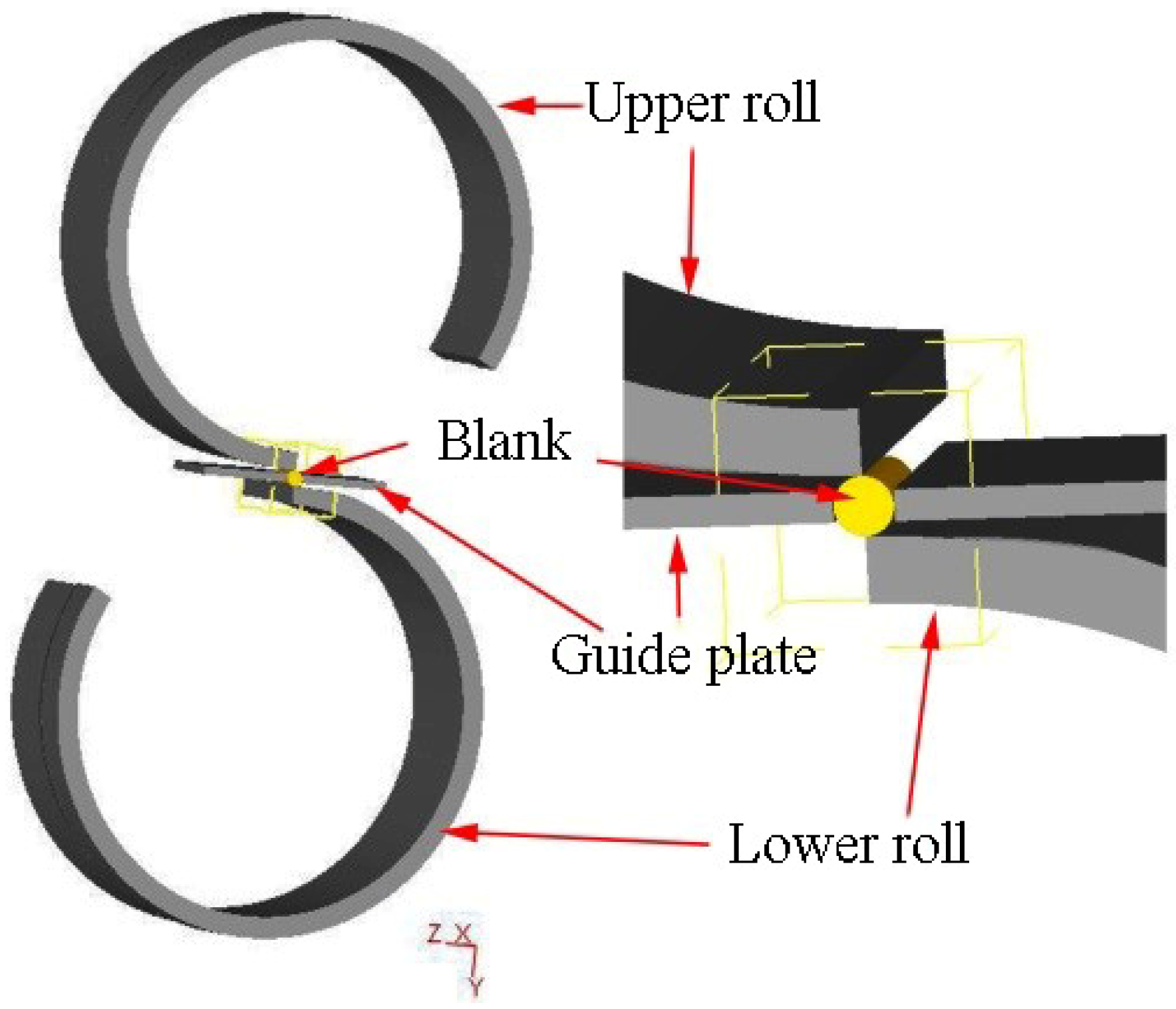
3. Establishment of a Finite Element Model

CWR is mainly conducted to form shaft parts. Figure 4 shows the plane layout of a CWR die, which is divided into three parts: the wedging, stretching, and finishing stages. The wedging stage mainly involves blanking out of a V-shaped groove to facilitate forming. The stretching stage is the main stage of the whole process of rolling forming, and the finishing stage involves modification of the components to improve the component’s accuracy and to meet size requirements.
The thermal deformation constitutive equation of the Ti-6Al-4V, obtained by the thermal simulation experiment was imported into Deform-3D [7,20,21,25], and a finite element model of engine blade forming by CWR was established. Figure 5 shows the finite element model, which is composed of two rollers, two guides, and one billet. According to the characteristics of Ti-6Al-4V the titanium alloy CWR, the following assumptions were made to improve the working efficiency of the model:
(1)
During CWR, large plastic deformation is observed on the rolled piece, and the elastic deformation is negligible. Therefore, the Ti-6Al-4V titanium alloy rolled piece can be considered as a plastic body, whilst the CWR die can be considered as a rigid body.
(2)
The Ti-6Al-4V titanium alloy is rolled symmetrically. For convenient calculations, only half of the rolled structure is selected for the simulation calculation. Symmetric constraint boundary conditions are defined at the symmetrical portion of the rolled piece.
(3)
Sheet metal forming usually adopts the Cullen friction. For bulk forming, shear friction is usually adopted, and the contact relationship between the rolling piece and the guide plate is neglected. The friction coefficient between the Ti-6Al-4V billet and the die is set to 0.7 as in References [7,19,27].
(4)
Deform automatically re-divides the grid when the cumulative maximum strain increment of the rolling piece is 0.7, to ensure that the software is sufficiently accurate without requiring excessive mesh repartitioning.
(5)
A thermodynamic coupling model is introduced. Considering various heat transfer processes, such as thermal convection, heat radiation, heat conduction, plastic deformation heat, and frictional heat, the heat transfer boundary is defined in the rolled piece, die, and the surrounding environment. When the ambient temperature is 20 °C, the heat radiation rate of the rolled piece is 0.7, the convection heat transfer coefficient between the rolled piece and the air is 250 W/m2·K, and the contact thermal conductivity between the rolled piece and the die is 11 × 103 W/m2·K.
(6)
An H500 CWR mill is selected with a die specification of Φ500 mm × 400 mm. On the basis of actual conditions, the speed of the roller rotation is set to 10 r/min in the numerical simulation.
The main parameters for the Ti-6Al-4V alloy blade CWR simulation are shown in Table 1. The main die parameters are shown in Table 2.

4. Results and Discussion

4.1. Forming Process

Figure 6 shows the Ti-6Al-4V blade CWR forming process. When t = 0.14 s in the wedging stage, the rolled piece bit into the cavity with rotation of the mold and a V groove was extruded from the symmetrical center of the rolled piece. With further rotation of the mold, the depth of the groove was gradually increased until the wedge was completed. The rolling zone of the rolled piece was compressed in the radial direction, and the outer diameter gradually decreased. When t = 1.06 s, the stretching stage was initiated, and the rolled piece continued to rotate under the function of the die type. Considering that the wedge height of the die was unchanged and that the width of the wedge die changed from narrow to wide, the metal in the deformation zone was further compressed by the die along the axial direction, and radial compression occurred to meet the size requirement. With increasing width, the rolled piece formed at t = 4.01 s. In the finishing stage, the rolled piece was rolled into the required size, and the surface quality was refined.

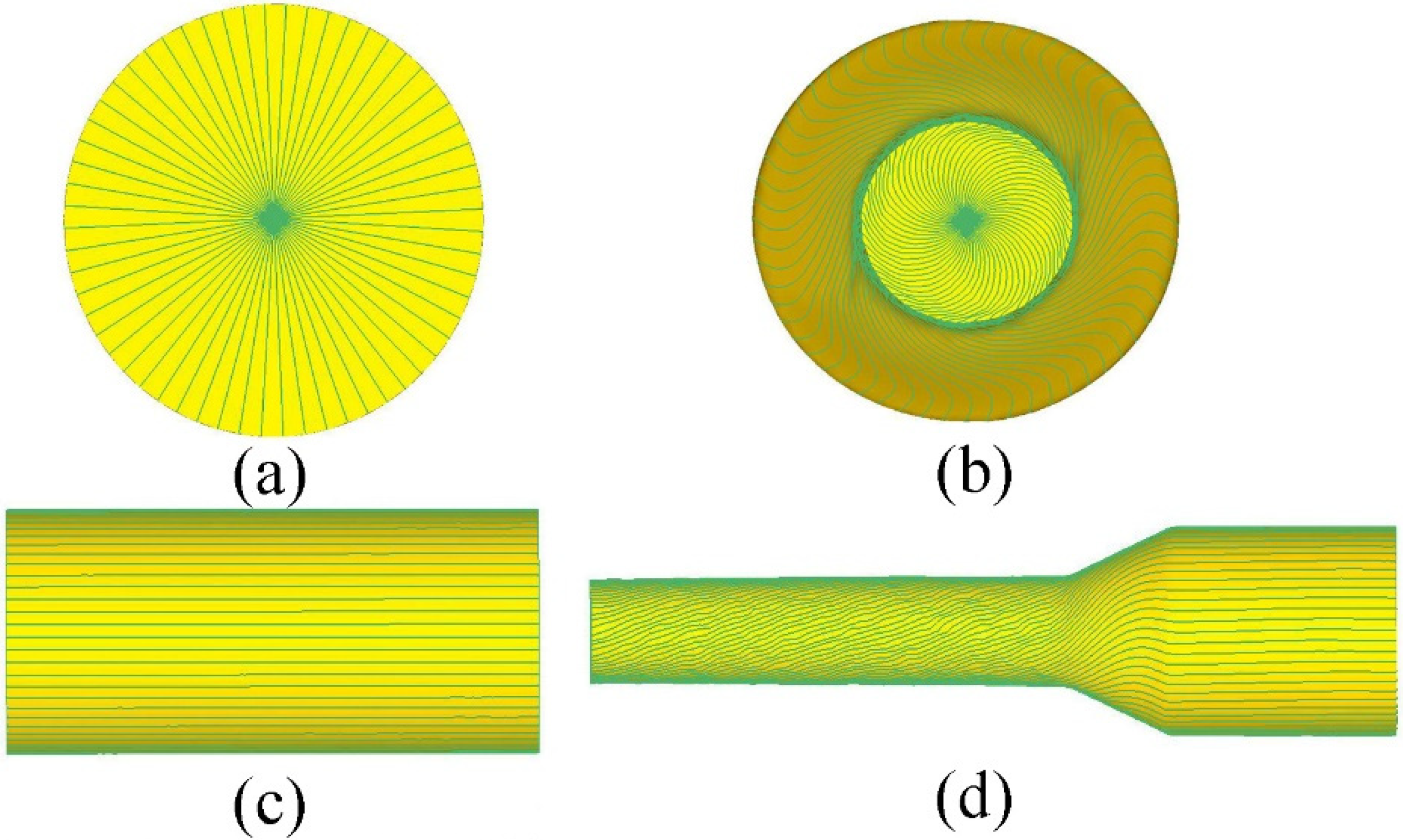
4.2. Law of Metal Flow

The mechanism of CWR forming can be reflected by observing the flow pattern of the metals. Rolling mainly drives metal flow according to the shape of the die until the piece is finally formed. Figure 7 shows the deformation of the rolled piece mesh before and after rolling. The main deformation of the rolled piece involved radial compression and axial extension. Figure 7a,b show the changes in the transverse mesh of the Ti-6Al-4V blade before and after the CWR; where the material was subjected to large torsion along the rolling direction. Figure 7c,d show schematics of the changes in the longitudinal mesh before and after the Ti-6Al-4V blade CWR. From the lower part of the rolling contact zone to the symmetrical center of the piece, the torsional degree of the mesh increased gradually, and the torsional direction was the same as that of the rolled piece. At the upper part of the rolling contact surface, the torsional direction was opposite to the rotational direction of the rolled piece. In the middle of the rolling contact surface, a point in the rolled piece that did not experience torsion was formed. This point was referred to as the K point, which reflected the non-relative sliding of the rolled piece and the die. In this position, the tangential velocities of the rolled piece and the die were equal. At a position below the K point, the linear velocity of the die was greater than that of the rolled piece. The surface metal of the rolled piece under the force of friction, with the die, experienced growth movement to the rolled piece rotation direction, resulting in torsional bias in the direction of the rolled piece. At a location higher than that of the K point, the linear velocity of the die was less than that of the rolled piece. The surface metal of the rolled piece was hindered by the die under the action of friction, and the motion was relatively lagged, resulting in torsion at the opposite direction of the rotation of the rolled piece.

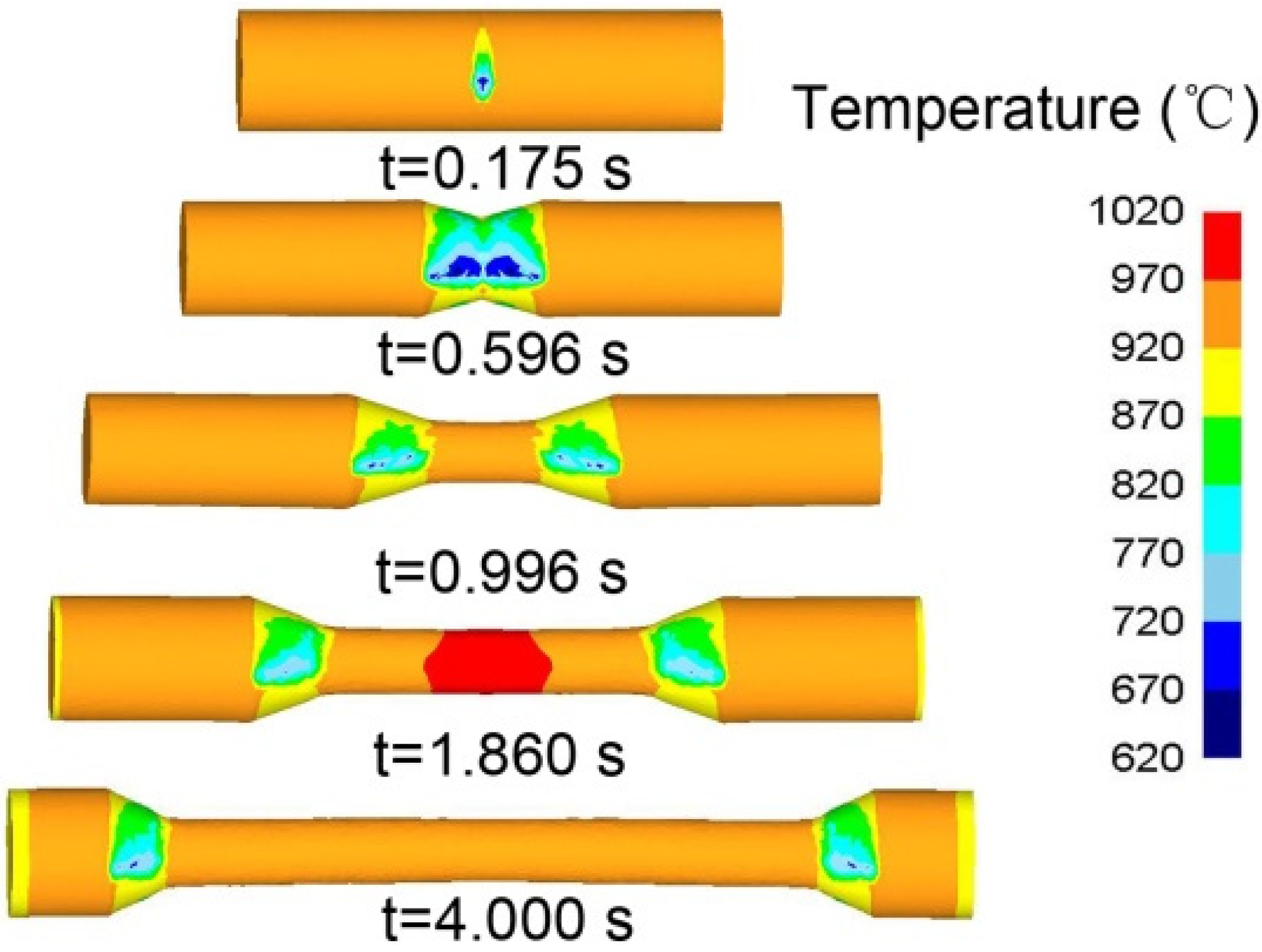
4.3. Temperature Distribution

Temperature was among the important factors affecting thermal processing. The Ti-6Al-4V blade rolling forming was also affected by temperature. Deform software was used to analyze temperature changes in the rolling process, as such this knowledge was of great significance in controlling the shaped microstructures. Figure 8 shows the changes in temperature during the rolling of the Ti-6Al-4V blade. Figure 8a shows the changes in temperature during the numerical simulation. In the wedging stage, when t = 0.175 s, the contact zone temperature of the rolled piece surface and the die was reduced rapidly. The temperature reached 820 °C, whereas the temperature of the core remained almost unchanged. At t = 0.596 s, the wedge was completed, and the surface temperature could reach 700 °C. In the stretching stage, when t = 0.996 s, the metal along the radial compression degree became larger, but the plastic work was inadequate to produce more heat. The temperature of the outer surface of the metal, which was under the action of the die, decreased. When t = 4.000 s, the forming process ended, and the temperature of the rolled piece decreased to about 900 °C, as shown by the numerical simulation. The temperature of the Ti-6Al-4V blade rolled piece was approximately 850 °C after CWR, as measured by the thermal imager (Figure 8b). This finding was consistent with and supported the results of the numerical simulation.

4.4. Stress Analysis

Figure 9a–c shows the directions of stress distribution of the Ti-6Al-4V rolled piece in the wedging, stretching, and finishing stages. In the wedging stage, the die cut a V groove on the surface of the rolled piece, where contact with the die exerted a maximum compressive stress of up to 130 MPa on the piece, and the equivalent stress from the contact point to the core of the rolled piece was gradually reduced. As the rolled piece entered the stretching stage, its stress distribution characteristics became identical to those of the wedging stage. Owing to the repeated rubbing of the metal during rolling, the various stresses indicated that the core was under tensile stress, reaching 300 MPa in the X, Y, and Z directions. Loose core defects roll out easily after rolling was completed. Finally, upon entering the finishing stage, the deformation was complete, and the contact parts of the rolled piece surface and the die were subjected to a compressive stress of approximately 50 MPa.

4.5. Strain Analysis

The core area point (P1), middle area point (P2), and the surface point (P3) of the rolled piece were taken to track strain changes during the forming process (Figure 10). To facilitate the analysis, the strain distribution of the three points was traced using a cylindrical coordinate system. Figure 11 shows that both the radial and tangential strains were compressive in nature, whereas the axial strain was tensile in nature before P2, P3, and P1 entered the rolling deformation area. Afterward, the radial strain of P1, P2, and P3 decreased rapidly. After 1.0 s, P1, P2, and P3 were always subjected to compressive strain. The variation trend of the tangential strain during rolling deformation was similar to that of the radial strain. The axial strain on P1 was subjected to a large tensile strain, which rapidly increased to 1.4 after rolling started. During rolling, the strain tended to remain constant. P1 and P2 showed a similar trend, which was maintained at about 1.1. The equivalent strain showed a large and rapid change in P1, which indicated that the deformation degree of the external point was greater than that of the other points. After entering the finishing stage, the strain tended to be stable. Overall, the strain values of the metals in the deformation area initially increased rapidly, whilst the radial and tangential strain experienced cyclic fluctuations. The axial strain increased rapidly and then stabilized.

4.6. Analysis of the Force Energy Parameters

Force energy parameters are an important reference value when selecting suitable rolling mill equipment and optimization of the mold parameters. A better understanding of the force energy parameters of the Ti-6Al-4V during CWR corresponds to a better understanding of the rolling rules. Figure 12a shows the change rules of the force energy parameters during the Ti-6Al-4V rolling. In the wedging stage, the rolled piece was in contact with the die. The contact area was small, which caused the rolling force to increase rapidly. Figure 12a shows that the rolling force increases rapidly from 0 kN to 5 kN. When the rolled piece began to wedge into the die, a small V groove formed, and the deformation resistance became large. Hence, a large rolling force was needed to overcome the deformation resistance of the rolled piece, resulting in a rapid increase in the rolling force. With the gradual increase in the wedge depth, the rolled piece entered the stretching stage. At a stable rolling force, the Ti-6Al-4V rolled piece was characterized by a radial compression and axial tensile state, with forces of 1.5, 2, and 5 kN in the X, Y, and Z directions, respectively. In the finishing stage, the contact area between the Ti-6Al-4V rolled piece and the die remained unchanged, and the rolling force was reduced to 0. Figure 12b illustrates the change rules of rolling torque in the rolling process. The maximum rolling torque was 4500 N·m in the wedging stage, and the steady rolling torque was 3500 N·m in the stretching stage and it decreased to 0 at the end of rolling.

5. Experimental Verification

The Ti-6Al-4V blade CWR blank test was completed at the part rolling center of the University of Science and Technology Beijing. A CWR mill and tube-type electric furnace were used in the equipment. Figure 13a shows the H500 CWR mill. According to the experimental configuration or die processing, a block-type die was adopted to cut the processing time and to reduce the experiment costs. To satisfy the experimental requirements, two sets of parameters were applied to each die. Subsequent experimental conditions were modified based on the results of the initial die, and the length of the material used in the experiment was 100 mm. The blank was placed into the tube-type electric furnace and it was heated to the corresponding rolling temperature before initiating the rolling experiment. Figure 13b shows the Ti-6Al-4V blade obtained after rolling; this blade was compliant with the size requirements. Table 3 shows the experimental data, which are consistent with the simulation results. The error was less than 2%, which indicated that the measurements were credible.

6. Conclusions

In this paper, the CWR billets of Ti-6Al-4V blades were thoroughly studied. Through theoretical analysis, numerical simulation, and rolling experiments, the following main conclusions were obtained.
(1)
The Gleeblel-1500D thermal simulation test was carried out, and the constitutive equation of the Ti-6Al-4V alloy was established. The rules of metal flow, temperature, stress–strain distribution, and rolling force during the CWR were systematically analyzed.
(2)
In the forming process of the Ti-6Al-4V alloy, the metal flows differed along the length of the rolled piece. The metal flowed quickly at the surface point, but it flowed slowly at the core area point. The axial flows of material from the interior to the exterior of the piece gradually increased toward the outer surface and then decreased. Increases in rolling length increased the difference between the axial flows.
(3)
When the Ti-6Al-4V alloy was formed, the rolling temperature was approximately 850–900 °C. From the trend of temperature change, in the axial direction, by rolling the middle symmetry plane, which was gradually reduced to both sides; in the radial, the temperature of rolled piece from the core area to surface was gradually decreased. Owing to the repeated rubbing of metal during rolling, the core area was subjected to tensile stress, which could reach 300 MPa in the X, Y, and Z directions. Hence, loose core defects appeared after the completion of rolling. In the forming process, the equivalent strain of the surface point was greater than that of the core and it gradually stabilized after entering the stretching stage.
(4)
In the process of the Ti-6Al-4V blade CWR blank, the forces were 1.5, 2, and 5 kN in the three directions at the stretching stage, and the maximum rolling torque was 4500 N·m.
(5)
The technology of the Ti-6Al-4V blade CWR blank is feasible and it presents great advantages in the production of Ti-6Al-4V blades.
In future work, the microstructure of the Ti-6Al-4V blade after CWR will be analyzed. Furthermore, research on the formation integration of the CWR of titanium alloy blades will be conducted to expand the industrial applications of this technology.

Author Contributions

Manuscript writing, H.J.; Literature search and production chart, J.D.; Data analysis, L.X.; Production chart, X.H.; Research design, J.L.

Funding

This work is supported by the Project funded by China Postdoctoral Science Foundation (Grant No. 2018M641186). This work is also supported by the National Natural Science Foundation of China (Grant No. 51505124). The Central University's special research funding fee is FRF-BD-17-003A (Grant No. FRF-BD-17-003A).

Conflicts of Interest

The authors declare no conflict of interest.

References

  1. Valoppi, B.; Ghiotti, A.; Bruschi, S. Elevated Temperature Behaviour of Ti6Al4V Sheets with Thermo-electro-chemical Modified Surfaces for Biomedi-cal Applications. J. Mater. Des. Appl. 2015. [Google Scholar] [CrossRef]
  2. Egea, A.J.S.; Rojas, H.A.G.; Celentano, D.J.; Peiró, J.; Cao, J. Thermomechanical Analysis of an Electrically Assisted Wire Drawing Process. J. Manuf. Sci. Eng. 2017, 139, 111017. [Google Scholar] [CrossRef]
  3. Valoppi, B.; Sánchez, E.; Antonio, J.; Zhang, Z.; González Rojas, H.; Ghiotti, A.; Bruschi, S.; Cao, J. A hybrid mixed double-sided incremental forming method for forming Ti6Al4V alloy. CIRP Ann. 2016, 65, 309–312. [Google Scholar] [CrossRef] [Green Version]
  4. Çakırcalı, M.; Kılıçaslan, C.; Güden, M.; Kıranlı, E.; Shchukin, V.; Petronko, V. Cross wedge rolling of a Ti6Al4V (ELI) alloy: The experimental studies and the finite element simulation of the deformation and failure. Int. J. Adv. Manuf. Technol. 2013, 65, 1273–1287. [Google Scholar] [CrossRef]
  5. Ji, S.; Li, Z.; Wang, Y.; Ma, L. Joint formation and mechanical properties of back heating assisted friction stir welded Ti-6Al-4V alloy. Mater. Des. 2017, 113, 37–46. [Google Scholar] [CrossRef]
  6. Zhao, A.M.; Yang, H.; Fan, X.; Gao, P.; Zuo, R.; Meng, M. The flow behavior and microstructure evolution during (α+β) deformation of β wrought TA15 titanium alloy. Mater. Des. 2016, 109, 112–122. [Google Scholar] [CrossRef]
  7. Li, J.; Wang, B.; Ji, H.; Huang, X.; Tang, X.; Ma, W. Effects of the cross-wedge rolling parameters on the formability of Ti-6Al-4V alloy. Int. J. Adv. Manuf. Technol. 2017, 92, 2217–2229. [Google Scholar] [CrossRef]
  8. Yang, L.; Wang, B.; Liu, G.; Zhao, H. Prediction model of tensile mechanical properties of TA15 sheet at room temperature based on internal variables. Chin. J. Nonferrous Met. 2015, 25, 652–661. [Google Scholar]
  9. Yang, L.; Wang, B.; Liu, G.; Zhao, H.; Xiao, W. Behavior and modeling of flow softening and ductile damage evolution in hot forming of TA15 alloy sheets. Mater. Des. 2015, 85, 135–148. [Google Scholar] [CrossRef]
  10. Yang, L.; Wang, B.; Liu, G.; Zhao, H.; Zhou, J. Hot Tensile Behavior and Self-consistent Constitutive Modeling of TA15 Titanium Alloy Sheets. J. Mater. Eng. Perform. 2015, 24, 4647–4655. [Google Scholar] [CrossRef]
  11. Zhao, H.; Wang, B.; Liu, G.; Yang, L. Unified constitutive model of TA15 titanium alloy in hot deformation based on the globularization mechanism. J. Univ. Sci. Technol. Beijing 2014, 36, 925–930. [Google Scholar]
  12. Xue, S. Study on the Forming Features and Process of Large Scale TA15 Titanium Alloy Aviation Structural Parts; Chongqing University, School of Material Science and Engineering: Chongqing, China, 2011; pp. 1–12. [Google Scholar]
  13. Pater, Z.; Tomczak, J.; Bulzak, T. New forming possibilities in cross wedge rolling processes. Arch. Civ. Mech. Eng. 2018, 18, 149–161. [Google Scholar] [CrossRef]
  14. Gontarz, A.; Pater, Z.; Tofil, A. Numerical analysis of unconventional forging process of hollowed shaft from Ti-6Al-4V alloy. J. Shanghai Jiaotong Univ. Sci. 2011, 16, 157–161. [Google Scholar] [CrossRef]
  15. Pater, Z. Theoretical and experimental analysis of cross wedge rolling process. Int. J. Mach. Tools Manuf. 2000, 40, 49–63. [Google Scholar] [CrossRef]
  16. Hu, Z.; Zhang, K.; Wang, B.; Shu, X.; Yang, C. The Forming Technology and Simulation of Parts with Cross Wedge Rolling; Metallurgical Industry Press: Beijing, China, 2004; pp. 88–124. [Google Scholar]
  17. Huang, J.; Liu, J.; Wang, B.; Hu, Z. Effect of Process Parameters on Surface Spiral in Cross Wedge Rolling of 4Cr9Si2. J. Northeast. Univ. Nat. Sci. 2014, 35, 1778–1782. [Google Scholar]
  18. Huang, J.; Liu, J.; Wang, B.; Hu, Z. Influence Analysis of Wedging Tip Fillet for Forming in the Process of Cross Wedge Rolling 4Cr9Si2 Valve. J. Mech. Eng. 2014, 24, 93–99. [Google Scholar] [CrossRef]
  19. Huang, J.; Liu, J.; Wang, B.; Hu, Z. Process research on 4Cr9Si2 martensite steel valve in CWR. J. Cent. South Univ. Sci. Technol. 2013, 44, 2744–2750. [Google Scholar]
  20. Huang, J.; Liu, J.; Wang, B. Effect of stretching angle on the forming quality of cross wedge rolling 4Cr9Si2 valves. J. Univ. Sci. Technol. Beijing 2013, 35, 1188–1194. [Google Scholar]
  21. Ji, H.; Liu, J.; Wang, B.; Zheng, Z.; Huang, J.; Hu, Z. Cross-wedge rolling of a 4Cr9Si2 hollow valve: Explorative experiment and finite element simulation. Int. J. Adv. Manuf. Technol. 2015, 77, 15–26. [Google Scholar] [CrossRef]
  22. Zhou, J.; Yu, Y.; Zeng, Q. Analysis and experimental studies of internal voids in multi-wedge cross wedge rolling stepped shaft. Int. J. Adv. Manuf. Technol. 2014, 72, 1559–1566. [Google Scholar] [CrossRef]
  23. Zhou, J.; Xiao, C.; Yu, Y.; Jia, Z. Influence of tool parameters on tool wear in two-roll cross-wedge rolling. Int. J. Adv. Manuf. Technol. 2013, 65, 745–753. [Google Scholar] [CrossRef]
  24. Jia, Z.; Zhou, J.; Ji, J.; Yu, Y.; Xiao, C. Influence of tool parameters on internal voids in cross wedge rolling of aluminum alloy parts. Trans. Nonferrous Met. Soc. China 2012, 22, s21–s26. [Google Scholar] [CrossRef]
  25. Huo, Y.; Lin, J.; Bai, Q.; Wang, B.; Tang, X.; Ji, H. Prediction of microstructure and ductile damage of a high-speed railway axle steel during cross wedge rolling. J. Mater. Process. Technol. 2017, 239, 359–369. [Google Scholar] [CrossRef]
  26. Huo, Y.; Wang, B.; Lin, J.; Zhou, J. Damage mechanisms research for the high-speed railway axle steel 25CrMo4 during hot cross wedge rolling. J. Northeast. Univ. Nat. Sci. 2013, 34, 1625–1629. [Google Scholar]
  27. Zhang, N.; Wang, B.; Lin, J. Effect of cross wedge rolling on the microstructure of GH4169 alloy. Int. J. Miner. Metall. Mater. 2012, 19, 836–842. [Google Scholar] [CrossRef]
  28. Zhang, N.; Wang, B.; Hu, Z. The Numerical Simulation of GH4169 Alloy during Cross Wedge Rolling. Adv. Mater. Res. 2011, 230–232, 384–388. [Google Scholar] [CrossRef]
  29. Zhang, N.; Wang, B.; Hu, Z. Thermomechanical coupled numerical simulation of GH4169 alloy for cross wedge rolling. J. Univ. Sci. Technol. Beijing 2011, 33, 1396–1401. [Google Scholar]
  30. Deng, Z.; Lovell, M.R.; Tagavi, K.A. Influence of Material Properties and Forming Velocity on the Interfacial Slip Characteristics of Cross Wedge Rolling. J. Manuf. Sci. Eng. 2001, 123, 647–653. [Google Scholar] [CrossRef]
  31. Zheng, Z.; Liu, J.; Wang, B.; Hu, Z. Effect of forming angle on the central quality of 21-4N valves by cross wedge rolling. J. Univ. Sci. Technol. Beijing 2013, 35, 228–233. [Google Scholar]
  32. Yan, X.; Liu, J.; Ji, H.; Wang, B.; Zheng, Z.; Li, Z. Effect of mandrel diameter on the wall thickness uniformity of the hollow valve of 5Cr21Mn9Ni4 by cross-wedge rolling. Chin. J. Eng. 2017, 39, 267–275. [Google Scholar]
  33. Ji, H.; Liu, J.; Wang, B.; Zhang, Z.; Zhang, T.; Hu, Z. Numerical analysis and experiment on cross wedge rolling and forging for engine valves. J. Mater. Process. Technol. 2015, 221, 233–242. [Google Scholar] [CrossRef]
  34. Ji, H.; Liu, J.; Wang, B.; Tang, X.; Lin, J.; Huo, Y. Microstructure evolution and constitutive equations for the high-temperature deformation of 5Cr21Mn9Ni4N heat-resistant steel. J. Alloys Compd. 2017, 693, 674–687. [Google Scholar] [CrossRef]
  35. He, T.; Wang, B.; Hu, Z. Thermal-mechanical coupled simulation of Inconel718 alloy cross wedge rolling. J. Plasticity Eng. 2008, 15, 157–159. [Google Scholar]
  36. Peng, W.; Zhu, J.; Shu, X. Influence of process parameters on thickness-radius ratio of cross-wedge rolling of Laminated shaft of 42CrMo/Q235 composites. Acta Mater. Compos. Sin. 2017, 34, 160–167. [Google Scholar]
  37. Peng, W.; Zheng, S.; Chiu, Y.; Shu, X.; Zhan, L. Multi-wedge Cross Wedge Rolling Process of 42CrMo4 Large and Long Hollow Shaft. Rare Met. Mater. Eng. 2016, 45, 836–842. [Google Scholar] [CrossRef]
  38. Huo, Y.; Bai, Q.; Wang, B.; Lin, J.; Zhou, J. A new application of unified constitutive equations for cross wedge rolling of a high-speed railway axle steel. J. Mater. Process. Technol. 2015, 223, 274–283. [Google Scholar] [CrossRef]
  39. Bulzak, T.; Pater, Z.; Tomczak, J. Numerical and experimental analysis of a cross wedge rolling process for producing ball studs. Arch. Civ. Mech. Eng. 2017, 17, 729–737. [Google Scholar] [CrossRef]
  40. Jia, Z.; Zhou, J.; Ji, J.; Lei, Z.; Xiang, D.; Sun, X. Influence analysis of area reduction for necking in twice-stage cross wedge rolling. Int. J. Adv. Manuf. Technol. 2013, 66, 1407–1413. [Google Scholar] [CrossRef]
  41. Yang, C.; Dong, H.; Hu, Z. Micro-mechanism of central damage formation during cross wedge rolling. J. Mater. Process. Technol. 2018, 252, 322–332. [Google Scholar] [CrossRef]
  42. Li, Q.; Lovell, M.R. Predicting Critical Friction in a Two-Roll Cross Wedge Rolling Process. J. Tribol. 2003, 125, 200–213. [Google Scholar] [CrossRef]
  43. Li, Q.; Lovell, M.R.; Slaughter, W.; Tagavi, K. Investigation of the morphology of internal defects in cross wedge rolling. J. Mater. Process. Technol. 2002, 125, 248–257. [Google Scholar] [CrossRef]
  44. Dong, Y.; Tagavi, K.A.; Lovell, M.R.; Deng, Z. Analysis of stress in cross wedge rolling with application to failure. Int. J. Mech. Sci. 2000, 42, 1233–1253. [Google Scholar] [CrossRef]
  45. Wang, M.; Li, X.; Du, F.; Zheng, Y. A coupled thermal–mechanical and microstructural simulation of the cross wedge rolling process and experimental verification. Mater. Sci. Eng. A 2005, 391, 305–312. [Google Scholar] [CrossRef]
  46. Wang, M.; Li, X.; Du, F.; Zheng, Y. Hot deformation of austenite and prediction of microstructure evolution of cross-wedge rolling. Mater. Sci. Eng. A 2004, 379, 133–140. [Google Scholar] [CrossRef]
  47. Zeng, J.; Xu, C.; Ren, W.; Li, P. Study on the deformation mechanism for forming shafts without concavity during the near-net forming cross wedge rolling process. Int. J. Adv. Manuf. Technol. 2017, 91, 127–136. [Google Scholar] [CrossRef]
  48. Ren, W.; Xu, C.; Zeng, J.; Li, P. Numerical simulation optimization and test on cross wedge rolling process of intermediate shaft. Forg. Stamp. Technol. 2017, 66–70. [Google Scholar] [CrossRef]
  49. Sun, Z.; Li, X.; Wu, H.; Yang, H. A unified growth model of the secondary grain boundary α phase in TA15 Ti-alloy. J. Alloys Compd. 2016, 689, 693–701. [Google Scholar] [CrossRef]
  50. Sun, Z.; Li, X.; Wu, H.; Yang, H. Morphology evolution and growth mechanism of the secondary Widmanstatten α phase in the TA15 Ti-alloy. Mater. Charact. 2016, 118, 167–174. [Google Scholar] [CrossRef]
  51. Wu, C.; Yang, H.; Li, H. Substructure and texture evolution and flow behavior of TA15 titanium alloy compressed in the alpha+beta two-phase field. J. Mater. Process. Technol. 2013, 213, 2033–2041. [Google Scholar]
  52. Xiao, J.; Li, D.; Li, X.; Deng, T. Constitutive modeling and microstructure change of Ti-6Al-4V during the hot tensile deformation. J. Alloys Compd. 2012, 541, 346–352. [Google Scholar] [CrossRef]
Figure 1. The 1500-D thermal simulation test machine.
Metals 08 01054 g001
Figure 2. The compression samples (unit: mm).
Metals 08 01054 g002
Figure 3. Ti-6Al-4V stress and strain curve (a) 850 °C (b) 950 °C; (c) 1000 °C; (d) 1050 °C.
Metals 08 01054 g003
Figure 4. Geometric model of the cross wedge rolling (CWR).
Metals 08 01054 g004
Figure 5. Finite element model of the CWR for Ti-6Al-4V.
Metals 08 01054 g005
Figure 6. Forming process of the CWR Ti-6Al-4V blade.
Metals 08 01054 g006
Figure 7. The deformation mesh during the CWR Ti-6Al-4V blade process, (a) The initial lateral mesh; (b) The lateral mesh after deformation; (c) The initial longitudinal mesh; (d) The longitudinal mesh after deformation.
Metals 08 01054 g007
Figure 8. The temperature distribution of the CWR Ti-6Al-4V blade process.
Metals 08 01054 g008
Figure 9. Stress distribution of the CWR Ti-6Al-4V blade rolling process (a) The wedging stage; (b) The Stretching stage; (c) The Finishing stage.
Metals 08 01054 g009aMetals 08 01054 g009b
Figure 10. The reference point location diagram.
Metals 08 01054 g010
Figure 11. The strain distribution of the CWR Ti-6Al-4V blade process. (a) Radial strain; (b) Tangential strain; (c) Axial strain; (d) Effective strain.
Metals 08 01054 g011
Figure 12. The distribution of forces and torque during CWR Ti-6Al-4V blade rolling process (a) The distribution of force; (b) The distribution of torque.
Metals 08 01054 g012
Figure 13. The experiment of the CWR Ti-6Al-4V blade (a) H500 mill; (b) The samples of rolled.
Metals 08 01054 g013
Table 1. Main parameters of the CWR simulation.
ParametersValue
Speed of roll10 (rpm)
The initial temperature of the material850 (°C)
Environment temperature20 (°C)
Heat transfer coefficient11 × 103 (W/m2·K)
Convection coefficient250 (W/m2·K)
Friction factor0.7
Mesh number for billet50,000
Billet materialTi-6Al-4V
Table 2. Main die parameters for simulation.
Working ConditionForming Angle (°)Stretching Angle (°)Area Reduction Rate (%)
130, 35, 40565.9
2353, 5, 7, 965.9
335551.2, 56.9, 65.9, 72.4
Table 3. Diameter distribution after rolling.
ProjectDesign ValueTest (mm)Relative Error (Exp)Numerical Simulation (mm)Relative Error (FEM)
110.5010.681.6%10.700.43%
210.5010.600.9%10.651.4%
310.5010.651.4%10.681.6%
410.5010.580.7%10.661.5%

