2. Experimental Method
The chemical composition of low carbon steel in this study was 0.053 C, 0.22 Si, 1.35 Mn, 0.082 (Nb + V + Ti), 0.0012 B, 0.23 Cr, 0.37 Mo balanced by Fe.
Specimens with dimensions of φ 6 × 50 mm were cut from the hot rolled steel plate along the transversal direction. The HAZ simulations were carried out using a thermo-mechanical simulator and a two dimensional Rykalin mathematical model was adopted to control the testing temperature. A Pt-10% Rh thermocouple was welded at the middle of the cylinders to monitor the temperature change during heat treatment. A linear variable displacement transducer type dilatometer was used to measure the relative change in diameter of these samples.
Specimens were heated to a peak temperature at a rate of 130 °C/s and held for 2 s. The peak temperature was set at 1350 and 1100 °C to obtain widely varying austenite grain sizes, which simulates the thermal cycles at coarse grained HAZ (CGHAZ) and fine grained HAZ (FGHAZ), respectively. The samples were then subjected to various cooling rates that were defined as the cooling time from 800 to 500 °C (the
t8/5 time varies from 5 to 600 s) until the phase transformation has completed.
Figure 1 shows the measured thermal cycle curves. Dilatation curves were obtained to determine the phase change temperatures. Continuous cooling transformation (CCT) diagrams for the CGHAZ and FGHAZ were constructed together to exhibit the effect of prior austenite grain size on phase transformation, although the CCT diagram of the CGHAZ has been reported elsewhere [
13].
The partially transformed bainite microstructure was expected to be retained using an interrupted cooling method by water quenching. Based on the CCT diagrams, the partial bainite transformation samples were quenched in water immediately after the welding thermal cycle temperature was lowered to 470, 500, or 550 °C, as signified with red arrows in
Figure 1.
For in situ observation of phase transformation, two samples were cut directly from the welding thermal simulation samples, machined into disks (6 mm diameter and 3 mm thickness), and then mechanically polished. These prepared samples were austenitized at 1300 °C and 1100 °C to simulate the CGHAZ and FGHAZ thermal cycles, respectively. The linear cooling rate of 2.5 °C/s was employed, which is approximately equal to the average cooling rate of the t8/5 = 120 s cooling time. The real-time information of phase transformation was recorded using high-temperature LSCM.
Metallographic specimens were cut from the heat treatment region of interest and then polished by conventional techniques. Microstructural characteristics were examined using an optical microscope(Leica DMIRM, Leica company, Weitz, Germany), a field-emission scanning electron microscope equipped with electron probe microanalysis (SEM, ULTRA 55, ZEISS, Jena, Germany), and a transmission electron microscope (TEM, FEI Tecnai G2F20, FEI company, Hillsboro, OR, USA). Vickers hardness measurements were conducted using an FM 700 hardness-testing machine (Hardness tester, FM-700, FUTURE-TECH company, Kawasaki-City, Japan) employing a 0.5 N load with 15 s dwell time. The average hardness values for each heat treatment condition were calculated based on at least 10 repeat tests.
3. Results and Discussion
On the basis of the dilatation curves (some typical examples were given in the literature [
11,
13]), the transformation start/finish temperatures could be confirmed with a normal extrapolation method [
15]. The CCT diagrams for CGHAZ and FGHAZ are constructed together in
Figure 2a. The transformation start temperature gradually lowers and the transformation finish temperature first increases, but then decreases with the decrease in cooling time. The bainite microstructure could be formed within a wide range of cooling rates, as marked in the diagram, which are attributed to the fact that the combined addition of multi-microalloys, such as Mo, Nb, Ti, and V, into steel extends the range of bainite transformation [
16]. As expected, FGHAZ always has a lower Bs temperature than CGHAZ for any given cooling rate (highlighted with gray background), although the discrepancy in bainite transformation finish temperature seems to be very insignificant. The largest difference in the Bs temperature between CGHAZ and FGHAZ is about 30 °C at the middle cooling rate.
Figure 2b shows the change of hardness with cooling time. As the cooling time increases, the hardness decreases rapidly and then gradually levels off. Meanwhile, at a given cooling rate, FGHAZ always seems to have a slightly higher hardness than CGHAZ. This further proves the difference in transformation behaviors (
Figure 2a) because the lower temperature transformation microstructure normally results in a higher hardness.
Figure 3 represents three groups of typical microstructures for CGHAZ and FGHAZ after they were subjected to the
t8/5 times of 5, 85, and 600 s, respectively. The average grain size of FGHAZ measured with the line intercept method ranges from about 16.8 μm to 29.5 μm, while CGHAZ has an average grain size higher than 300 μm. At the shortest cooling time, the microstructure is predominantly lath martensite, accompanied by very little bainitic ferrite, regardless of peak temperature (
Figure 3a,d). Comparing
Figure 3a and d, the packet size of martensite in the morphology seems to be refined by the fine prior grain size (
Figure 3e). Because of the hierarchical structure of martensite [
2,
3,
4,
5], the block size and lath width may be also decreased in FGHAZ.
At the cooling time (85 s), CGHAZ and FGHAZ microstructures are mainly characterized by bainitic ferrite (
Figure 3b,e). However, the martensite–austenite (MA) constituents that are formed below the Ms temperature as a result of incomplete bainite transformation [
17] have different sizes and distribution sites, although most of them have a similar short and slender shape. For example, the MA constituents in CGHAZ are present inside the grains and their distribution approximately describes some sites of parallel lath boundaries [
17]; while in FGHAZ, most of them appear along the prior austenite grain boundaries (signified with arrows in
Figure 3e), which seems to make the grain boundaries coarser. The distribution of MA constituents implies that the redistribution of carbon atoms is different during the transformation for CGHAZ and FGHAZ, because notable enrichment of carbon was observed within the MA constituents using atom probe tomography (APT) [
18].
As the cooling time increases to 600 s, the predominant microstructure for CGHAZ and FGHAZ becomes granular bainite (
Figure 3c,f). The MA constituents have a massive shape, mainly because the uphill diffusion of carbon atoms becomes much easier at the lower cooling rate condition [
19]. However, for CGHAZ, most massive MA constituents distribute uniformly in the matrix, except that a few of the MA constituents appear along the prior austenite grain boundaries, whereas in FGHAZ, they seem to have a larger average size and are mainly attached to the grain boundaries, as signified by arrows in
Figure 3c,f. Because CGHAZ and FGHAZ have similar microstructures, the difference of MA constituents should be mainly attributed to the number of grain boundaries (i.e., prior austenite grain size), as the grain boundary has a higher diffusivity for interstitial atoms (including C, B, and H) than the grain interior and also act as a sink for these atoms [
20,
21,
22].
Using the high temperature LSCM observation, the real-time features of bainite at the early stage of the transformation were recorded, as shown in
Figure 4 and
Figure 5. The phase transformation does not occur when the temperature decreases to 634 °C (
Figure 4a). The first ferritic lath can be found at 632 °C and its nucleation site is exactly on the grain boundary, as signified with an arrow in
Figure 4b. However, this temperature is higher than that detected using a dilatometer (
Figure 2a). This difference is probably acceptable as the dilatometer sensitivity is about 10 percent volume fraction transformed and the free surface effect of the LSCM sample can enhance the transformation temperature [
23]. With a further slightly decreasing temperature (629 °C), several ferritic laths form, simultaneously attached to the grain boundaries (
Figure 4c). Meanwhile, it is very interesting to find that a newly formed ferritic lath sympathetically nucleates on the pre-existing ferritic lath and grows toward the other direction, as marked with a cycled white arrow. This mechanism is a necessity that gives rise to the interlocked distribution of bainitic ferrite packets and partitions the coarse austenite grains into several finer and separate regions [
24]. Nevertheless, other grains still do not occur in phase transformation, which means the bainite formation is inhomogeneous at the grain scale. This agrees well with the results by Sainis et al. [
25], who found that the rate of nucleation varies markedly between different austenite grains.
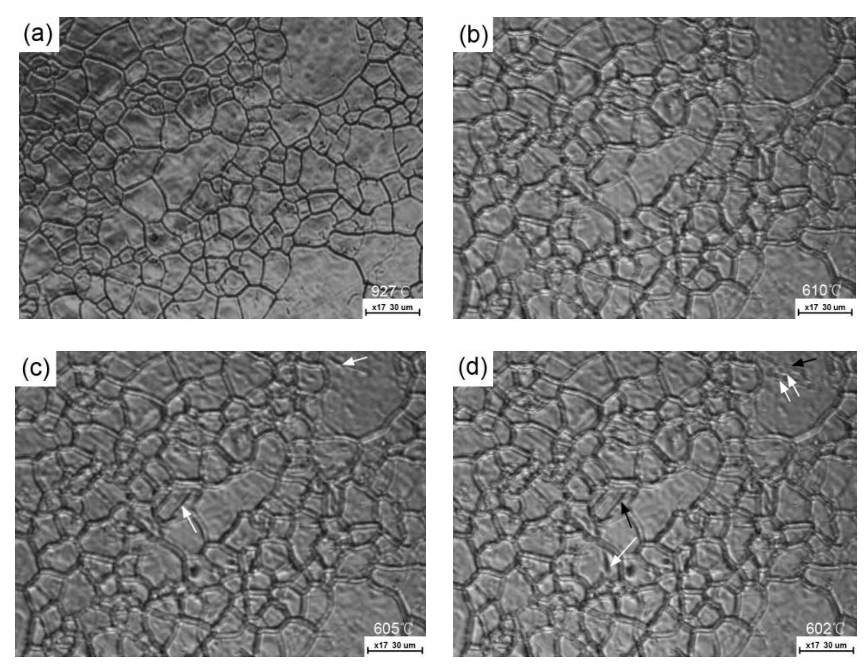
For the FGHAZ thermal cycle, the austenite grains are smaller and their size is more uniform (
Figure 5a) compared with that of CGHAZ. When the temperature decreases to 610 °C, no obvious phase transformation takes place (
Figure 5b). The ferritic laths can first be found at 605 °C, and their nucleation sites are also derived from the austenite grain boundaries (arrowed in
Figure 5c), although the image quality was not as good as before. The growth rate of these ferritic laths seems to be very fast, leading to their length across almost the prior austenite grain in no time. Subsequently, the newly formed bainitic laths appear in a “side-by-side” mode relative to the pre-existing laths, rather than an interlocked mode as in CGHAZ with the decrease in temperature (
Figure 5d), indicating that this mode may make only a packet structure in the morphology formed inside each fine prior austenite grain [
14]. According to these real-time micrographs, it is confirmed that the fine austenite grain size decreases the Bs temperature by about 30 °C, which is in good agreement with the dilatation tests.
Figure 6 shows the partially transformed bainite microstructure after the samples were subjected to partial welding thermal cycle cooling, followed by water quenching. At the very beginning of phase transformation, the lath morphology of ferrite forms and the nucleation of these ferritic laths are attached to the grain boundary (
Figure 6a). With the progress of bainite transformation (
Figure 6b), the packet structure of bainite can clearly be found as the carbides or MA constituents decorate the parallel lath boundaries. Several primary ferritic laths nucleate at different sites of the grain boundary inside one large prior austenite grain (marked with black arrows in
Figure 6b), and many secondary laths sympathetically nucleate on the pre-existing ferritic laths (signified with white arrows), which agrees well with the LSCM results (
Figure 4c). Through close observation of the nucleation sites of the primary laths, no MA constituents can be found, implying that in this case, the carbon atoms do not enrich at the nucleation sites of the prior austenite grain boundaries. On the contrary, most of carbon atoms should be expelled into the lath boundaries during transformation.
Only a small amount of bainite microstructures can be found for the FGHAZ sample (
Figure 6c) when the quenching temperature decreases to 500 °C. The prior austenite grain boundaries seem to be particularly evident (arrowed in
Figure 6c) compared with these in
Figure 6a using the same etchant solution. The lath boundaries of bainite in the vicinity of prior austenite grain boundaries are ambiguous as almost no any carbide was formed to decorate these lath boundaries in these micro-regions (
Figure 6d). An electron probe microanalysis on carbon distribution along the AB line (
Figure 6d) across a prior austenite grain boundary semi-quantitatively shows that the prior austenite grain boundary with MA constituent contains much higher carbon concentration compared with the grain interior (
Figure 6e).
Several TEM images were joined together in
Figure 7 to show the morphology of bainite formed inside a fine prior austenite grain. Each of ferritic laths seem to be composed of several sub-units (one of which was delineated) and very few of MA constituents can be formed along the lath boundaries. These features are different from the morphology of bainite formed in coarse prior austenite grains (the lath boundaries are always decorated by the slender MA constituents shown in
Figure 5d of the literature [
13]). Based on the bainite transformation theory, these sub-units formed with a limited size may be attributed to the fact that the increase in strength of austenite due to a relatively lower transformation temperature or the limited space of ferritic growth impedes the plastic accommodation of remaining austenite for transformation strain [
26].
Most interestingly, the prior grain boundaries are decorated by many long strip MA constituents with an average width of about 0.4 μm, as signified with white arrows (
Figure 7). The magnified image in
Figure 8 shows they have a character of high density dislocation martensite, which implies that the austenite along the grain boundaries is stabilized by carbon enrichment at these micro-zones, and most of them transform into martensite during final quenching. From the morphology of ferritic lath point of view, these carbon atoms enriched at the grain boundaries are considered to occur in super-cooled austenite at very early stages of the transformation or even prior to the transformation. Assuming that these segregated carbon atoms are expelled from the product phase during the transformation, they should be enriched in front of the phase interface and a quasi-eutectoid structure is likely to be formed [
27], as presented in CGHAZ.
4. Overall Discussion
The size and distribution of MA constituents are different between CGAHZ and FGHAZ, regardless of similar microstructures under any cooling time condition (e.g.,
Figure 3 and
Figure 6). This means that the prior austenite grain size to some extent influences the redistribution of carbon atoms before and after the transformation, as schematically shown in
Figure 9. The distribution of carbon atoms should be very uniform in CGHAZ grains at elevated temperatures (
Figure 9a), as the solid solubility of carbon in austenite increases with the temperature. Additionally, the number of vacancies generated inside the grains increases with the temperature, and they bind with carbon atoms to form stable carbon–vacancy pairs [
20,
28]. As a result, the carbon atoms uniformly distribute in super-cooled austenite for CGHAZ. During the transformation, the excess carbon atoms for BCC crystals are expelled in front of the phase interface into the lath boundaries (
Figure 9b).
The carbon atoms segregated along the prior austenite grain boundaries for FGHAZ (
Figure 9c) may be derived from the following two reasons. First, the grain boundary acts as a sink for vacancies. The higher the density of grain boundaries, the easier the grain boundary segregation of carbon atoms occurs because of the equilibrium and non-equilibrium segregation mechanism [
29]. Second, the trend of carbon diffusion into the grain boundaries may be enhanced as a result of the lowering solid solubility of carbon in super-cooled austenite. However, the distance of carbon diffusion in FGHAZ is much shorter than in CGHAZ, and the carbon diffusivity along the grain boundary is higher than inside the grains [
22], which gives rise to the presence of carbon enrichment at the grain boundaries for the FGHAZ (
Figure 9c), and the grain boundaries were finally decorated with the MA constituents (
Figure 9d). Timokhina et al. [
30] found that two types of the remaining austenite with different lattice parameters are present as a result of different carbon content at the beginning of the transformation using an in situ neutron diffraction technique. This means that the carbon redistribution does occur at the very early stage of the transformation, which seems to be in support of our result that the carbon atoms may be segregated at the prior grain boundaries prior to the transformation, although the present steel used has a much lower carbon content.
Zhang et al. [
20] considered that the prior austenite grain boundaries, which are high-energy regions with disordered atomic arrangements, could accommodate a number of carbon atoms and thus decrease the overall energy. In this sense, the difference in the carbon concentration of the grain boundary will change the overall boundary energy, which further influences the drive force of grain boundary nucleation. Therefore, carbon segregation at the grain boundaries in FGHAZ mentioned above is probably responsible for the difference in Bs temperature. More details are discussed below.
According to the classical nucleation theory, the free energy ∆
G for nucleation at prior austenite grain boundaries is given by [
31,
32]
where ∆
Gchem is the molar chemical Gibbs energy difference between the parent and product phase, ∆
Gstr is the summation of molar strain energy resulting from the volume misfit between ferrite and austenite (i.e., transformation strain), and ∆
Gint is the molar interfacial energy for the new phase formed. The latter two items are the resistance to phase transformation. If the transformation strain can be accommodated by the plastic deformation of austenite, the required strain energy for the creation of a new nucleus is much lower. The grain boundary nucleation thus occurs under the low transformation driving force condition, as presented in CGHAZ. However, the plastic accommodation in fine austenite grains is largely constrained by the Hall–Petch strengthening effect. As a result, it is always considered to be the main factor to decrease the Bs and Ms temperatures [
1,
3,
10,
23], because a larger super-cooled temperature is required to proceed to the phase transformation.
Very little strain energy seems to be required at the early stage of the bainite transformation as the transformation strain is insignificant at this point [
30]. Here, the change of interfacial energy probably plays a vital role in decreasing Bs temperature as a result of carbon segregation at the grain boundary. The heterogeneous nucleation attached to the grain boundary is mainly attributed to the fact that the prior grain boundary energy decreases the interfacial energy of new-phase nucleation. Song et al. [
32] showed that the maximum reduction of interfacial energy can be achieved when the embryo forms at the high-energy austenite grain boundary. However, the austenite grain boundary energy will be reduced if the excess carbon atoms are segregated on them, leading to the fact that the energy assisting the new-phase nucleation is lowered. Madariaga et al. [
33] also considered that grain boundary segregation has an influence on new-phase nucleation through the associated change of the interfacial energy and, presumably, of the structure of the boundary itself. On the basis of the partially transformed microstructure (
Figure 8), the width of carbon enriched micro-zones at grain boundaries is around 0.4 μm in FGHAZ. This means that the actual nucleation sites of ferritic laths are some distance (maybe about 0.2 μm) away from the grain boundaries. The nucleation of ferritic laths might not even take advantage of the prior austenite grain boundary energy. Therefore, it can be concluded that compared with CGHAZ, a larger driving force of transformation is needed to offset the increase in interfacial energy of nucleation for FGHAZ, which is embodied in the lower in Bs temperature.

