2. Materials and Methods
In order to generate graded rod-shaped materials, the process of gradation extrusion was developed. For detailed characterization of the microstructural evolution during processing, a unique extrusion die was designed and manufactured.
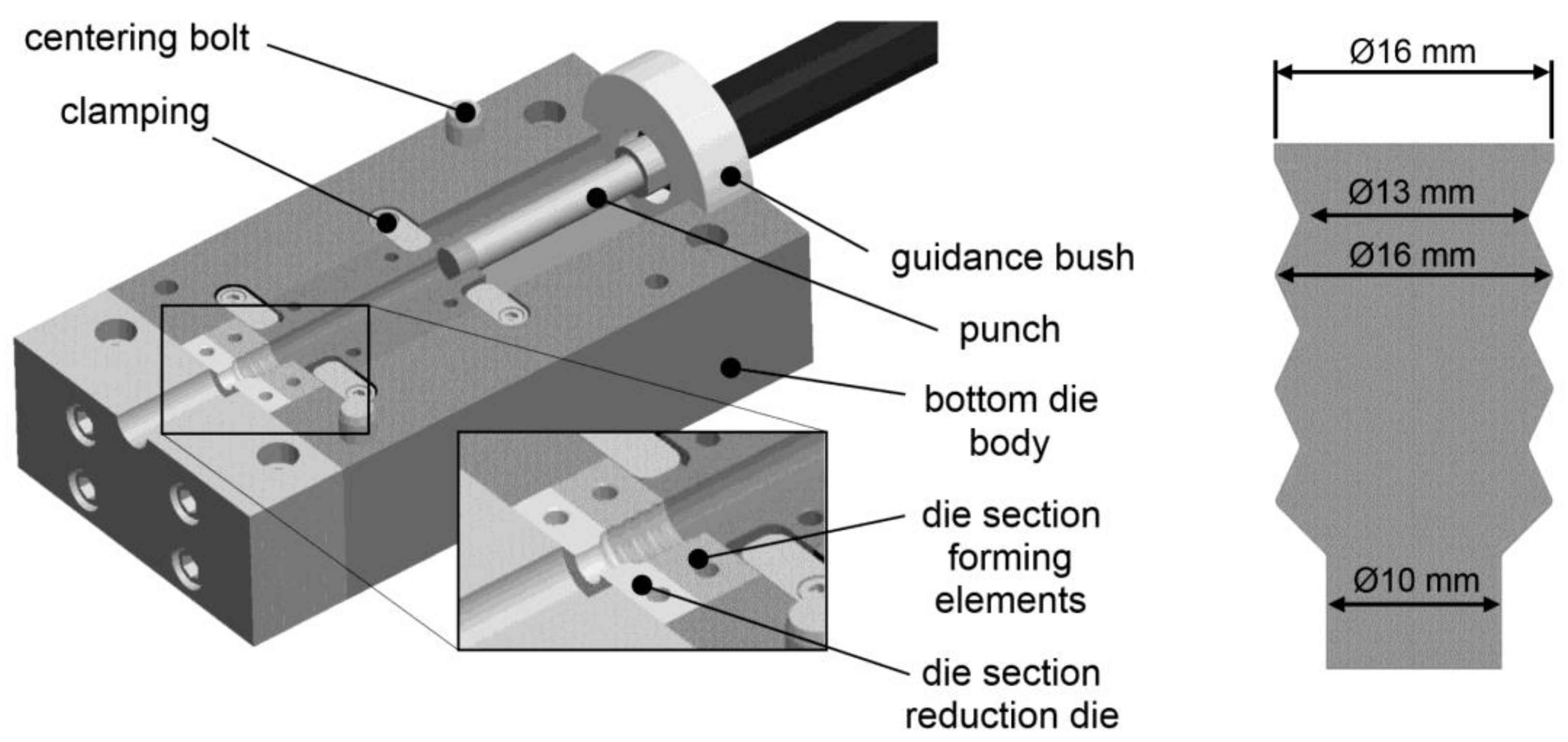
In contrast to conventional extrusion dies, the die is separated into an upper part and a lower die part. The separation plane is in the longitudinal direction and contains the axis of symmetry. This design allows for the removal of the processed billet. This is a basic requirement for a systematic characterization of microstructural evolution since the steady-state material flow is stopped at a certain point of extrusion. The billet can easily be removed without any damage or additional influence on the microstructure. The die parts are closed and compressed with a hydraulic press during forming, as presented in greater detail in [
27]. The second distinct feature is another separation of the die into a gradation element and an extrusion element (see
Figure 2). This design also allows different combinations (i.e., different relative contributions to the overall deformation) of gradation and extrusion.
The die was mounted in a hydraulic press with a maximum capacity of 15 MN in order to close the die parts. An additional horizontal hydraulic cylinder with a maximum capacity of 2.5 MN provided the necessary pressing force for gradation extrusion. The gradation extrusion was performed at room temperature. Due to the low pressing speed of 1 mm/s during the extrusion experiments, quasi-adiabatic heating was prevented. Note that the pressing speed is a major processing factor that influences several aspects of the forming process like temperature gradients and failure mechanisms. Further details on the influence of pressing speed in conjunction with other parameters such as die geometry are discussed elsewhere [
28]. In order to reduce friction during the gradation extrusion experiments, a commercial lubricant spray containing molybdenum disulfide and graphite that is commonly used for SPD processes [
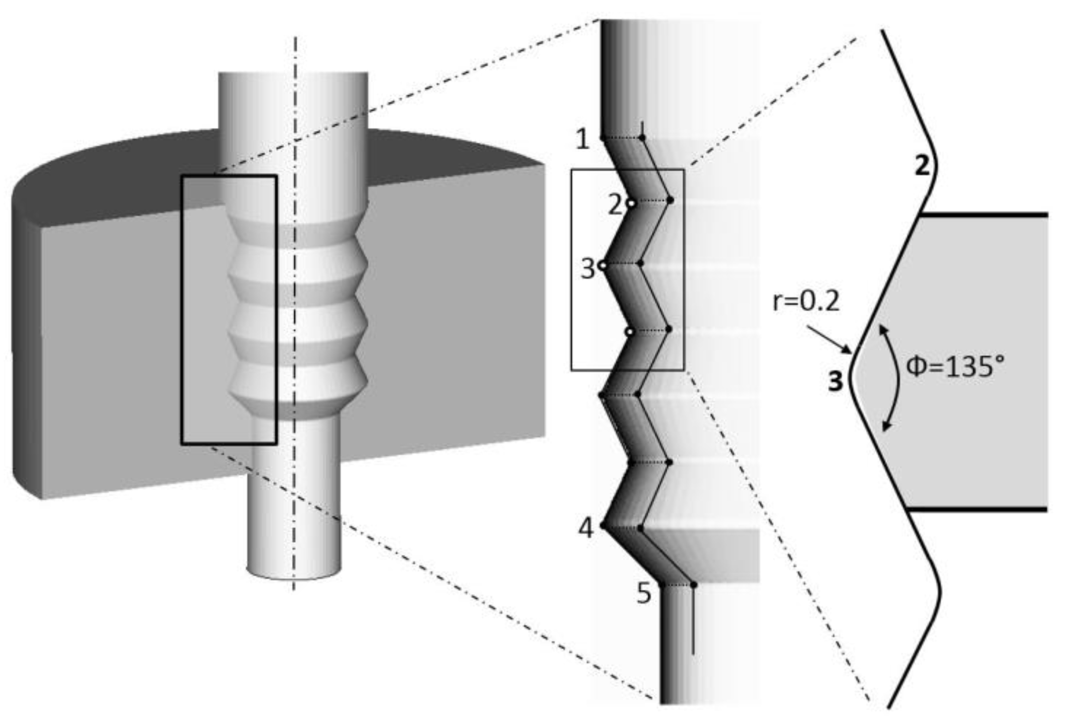
31] was applied on the cavity surface. The initial diameter of the billets was 16 mm and the minimum diameter of the concave forming elements was 13 mm. The maximum diameter of the convex forming elements was 16 mm. The final reduction leads to a diameter of 10 mm (see
Figure 2).
In this study, gradation extrusion was performed using an age-hardenable aluminum alloy AA6082. The chemical composition of the investigated material can be found in
Table 1. Prior to processing, the initial AA6082 alloy was solid solution annealed and naturally aged (T4). This alloy is often used for extrusion due to its high formability and strength. The initial material was commercially hot extruded and exhibits a typical near-surface zone characterized by large equiaxed grains, which results from dynamic recrystallization and pronounced grain growth in this highly strained region [
32,
33,
34].
After interrupted gradation extrusion, the billet was removed from the die and split lengthwise for mechanical and microstructural investigations. Hardness mapping (HV0.5) of an extruded billet was performed with the help of an automatic hardness tester (KB250BVRZ, KB Prüftechnik GmbH, Hochdorf-Assenheim, Germany). An equidistant grid was prepared with a spacing of 0.5 mm between individual indents and at a distance of 0.2 mm from the billet’s outer surface.
Microstructural evolution during gradation extrusion was investigated using the opposite part of the lengthwise-split billet. Surfaces of longitudinal sections were prepared as described in [
35] with a final finishing step of vibrational polishing. All micrographs presented in this paper were recorded with a viewing direction parallel to the normal direction of the specimen. The microstructure was investigated by scanning electron microscopy (SEM) using a field-emission device (Zeiss NEON 40 EsB, Zeiss, Jena, Germany) equipped with a backscatter electron detector (BSD) and an electron backscatter diffraction (EBSD) system (OIM 5.2, EDAX TSL, Mahwah, NJ, USA) which was operated at 15 kV with the 60 µm aperture in high current mode. EBSD data sets were typically recorded in regions of interest of 250 µm × 1000 µm with a step size of 3 µm, and of 15 µm × 15 µm with a step size of 50 nm, respectively. The EBSD data were subjected to a slight cleanup procedure comprising neighbor confidence index (CI) correlation and grain CI standardization with a minimum confidence index of 0.1. Parameters for grain size and grain aspect ratio determination were set to 15° tolerance angle, a minimum of 5 hits per grain, and a minimum CI of 0.1.
In order to compare the effective strains during gradation extrusion with other SPD processes, Finite Element (FE) simulations were performed. The finite element simulation includes work hardening of the material and friction between die and sample. The simulation setup and processing simulation were performed using the software Simufact Forming (version 13.3). The processes were set up as rotationally symmetric 2D models since the investigated die geometries are rotationally symmetric. A total of 7209 elements (element length 0.3 mm) of type advancing front quad were used. Both tool parts (punch and die) were defined as rigid bodies. The material and friction description used for the numerical simulation are summarized in
Table 2 [
28], where
ϕ corresponds to true strain.
3. Results and Discussion
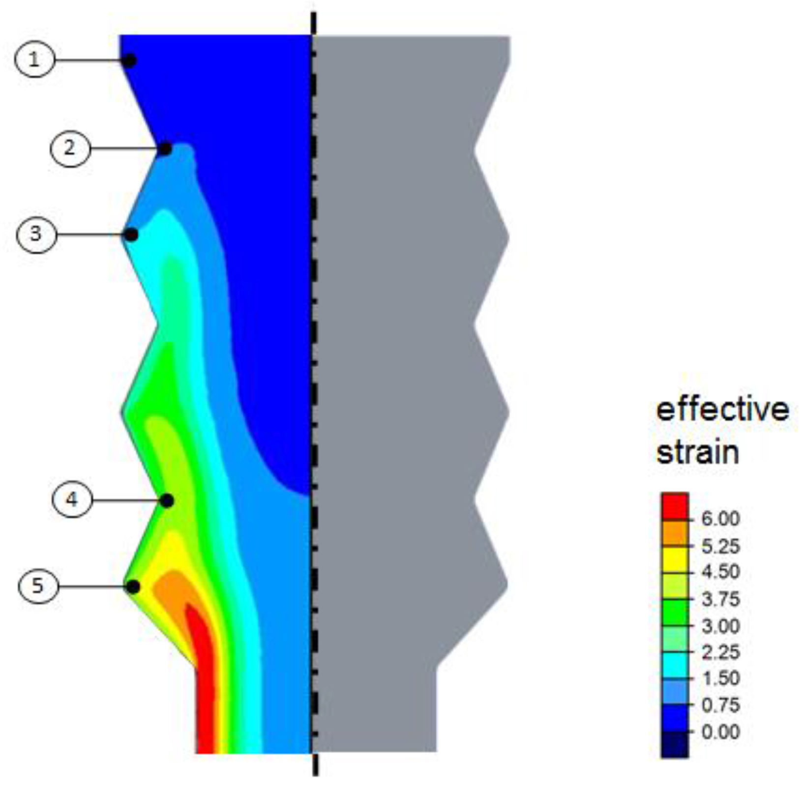
Figure 3 shows the distribution of effective (plastic) strain obtained from the FE simulation representing the steady state of material flow. A pronounced gradient of effective strain was found from the interior region to the surface. This gradient increases with every forming element in the axial direction. The final cross-sectional reduction leads to an additional introduction of strain, resulting in a final gradient ranging approximately from 1.4 (interior) to 6.9 (surface). The process basically fulfills the requirements for severe plastic deformation processes (SPD processes) since large effective strains, load path changes, high hydrostatic pressure, and temperatures below recrystallization temperature are applied. These results show that processing by gradation extrusion has a high potential for grain refinement by SPD, which leads to the assumption that distinct microstructural gradients may occur [
28]. For a detailed analysis of the microstructure discussed below, five distinct locations are highlighted in
Figure 3, representing interesting stages of deformation history during processing.
Figure 4 shows a processed billet of the investigated AA6082 alloy. The billet exhibits a smooth surface and no cracks have been found. It is also obvious that the cavities of all forming elements have been sufficiently filled with material, which indicates that the process of gradation extrusion was successfully performed. Both this experimental observation and the results of the FE simulation highlight that the requirements for a well-defined microstructural refinement by SPD are fulfilled.
The initial material for gradation extrusion was first analyzed by SEM and EBSD (
Figure 5). The microstructure of the commercially extruded AA6082 alloy is characterized by elongated fine grains in the interior region of the billet and by a surface area with a considerably coarsened grain structure. The mean grain size of the interior region is 10.2 (±2.3) µm and grains have a grain shape aspect ratio of 3. The shape of the grains in the interior region can be rationalized with the extrusion process of the initial material. This structure is a typical extrusion pancake structure [
36]. The surface area has a thickness of approximately 200 µm and is characterized by almost equiaxed large grains with a diameter of about 150 µm. The exceptionally large shear strains introduced into the surface area, accompanied by quasi-adiabatic heating during commercial direct extrusion in conjunction with an overall high pressing temperature, lead to intensive dynamic recrystallization and grain growth in the surface area [
36]. Furthermore, a typical strong <111> fiber texture accompanied by a <100> fiber texture caused by extrusion is found (see also
Figure 5).
As already shown by the FE simulation (
Figure 3), processing by gradation extrusion leads to microstructural changes due to incremental shear deformation by severe plastic deformation, especially in the surface area [
36].
Figure 6 shows the contour of a gradation-extruded lengthwise-cut billet. The incremental deformation is realized by three concave and three convex, alternatingly arranged forming elements and by a subsequent reduction of the circular cross section. With the help of a hardness mapping on this lengthwise-split extrusion billet, a pronounced hardness gradient was documented. It was found that hardness does not change in the interior region while it rapidly increases (by 20%) in the surface area along the first concave and convex forming elements. At Point 3, the maximum hardness at the surface was observed. Moreover, these maximum hardness values were measured up to a depth of approximately 2 mm from the surface, which is the deepest uniformly distributed hardness all over the specimen.
From the point of view of obtaining a maximum gradation in terms of hardness, the processing should be finished after Point 3: Additional forming elements for gradation extrusion lead to a decrease in hardness and a less-pronounced gradient of mechanical properties at the second concave and convex forming elements. This can be rationalized with dynamic recovery and/or recrystallization due to undesired heating by friction and severe local straining. At the last concave and convex forming element (Point 4), an increase of hardness and, therefore, an increased gradient is observed again. It is assumed that a repeated increase in strain hardening caused by dislocation and defect multiplication of the dynamically recrystallized material leads to the observed increase in hardness. As a result, the last two concave and convex forming elements do not increase the hardness gradient. The final cavity involving a reduction of the cross section at Point 5 results in a homogenization of the hardness gradient, while the magnitude of the gradient itself remains. The zone of maximum hardness exhibits a constant width of approximately 1 mm and a thin transition region to the softer interior region of the billet is hardly affected by gradation extrusion.
The history of deformation during gradation extrusion that first has been characterized by hardness measurements was furthermore rationalized by accompanying microstructural investigations at the same five points of interest (
Figure 6). For this investigation, the split billet was analyzed with the help of EBSD.
Figure 6b–f corresponds to the points from the hardness mapping, respectively. At all five points, an EBSD measurement (at the same point) was performed using identical parameters. Each of
Figure 6b–f shows an orientation map (OM) and the corresponding image quality map (IQ) below. This methodology allows a sufficient comparison of grain sizes, orientation data, and elongation of the grains at all five investigated points. The (severely strained) surface area is located on the left for each OM/IQ image. IQ maps give a qualitative indication of the magnitude of inherent strain. A brighter IQ image is associated with less lattice distortion and, therefore, lower inherent strains, and highly strained regions as well as grain boundaries typically show low/dark band contrast [
37]. Note that microstructural features of the surface region are discussed in greater detail below (see also
Figure 7).
Figure 6b corresponds to Point 1 and represents the initial condition of the material prior to gradation extrusion. As already shown in
Figure 5, the surface area (~200 µm thickness) is characterized by almost equiaxed large grains (diameter ~150 µm) resulting from a pronounced dynamic recrystallization which is also confirmed by lower hardness values in this region. Underneath the coarse-grained surface region, the microstructure is characterized by elongated fine grains and a homogeneous pancake-like structure. The bright IQ image reveals a very low magnitude of inherent strain resulting from the commercial hot extrusion accompanied by pronounced recovery/recrystallization.
Figure 6c corresponds to Point 2 and represents the condition after the first concave forming element with an effective strain of approximately 1.4. Due to this severe plastic deformation, grain refinement occurs (comparable to other SPD microstructures) within the first 150 µm from the surface. The formerly coarse grains of the surface region are considerably refined compared to those of the interior region. Furthermore, a slight rotation of the grains can be observed originating from the material’s flow through the cavity at Point 2. From the orientation map, it can be concluded that after about 300 µm from the surface, the microstructure is almost similar to that of the interior region of the initial material. However, the introduced work hardening indicated by the dark IQ map extends to about 500 µm. Work hardening and grain refinement during this local severe plastic deformation led to a considerable increase in hardness.
Figure 6d corresponds to Point 3 and represents the condition after the first concave and convex forming element with an effective strain of approximately 2.1. The maximum hardness at this point can be rationalized by the additional strain hardening and grain refinement induced by SPD. Considerable grain refinement is found within a region of about 250 µm from the billet surface. Again, the highly strained region is much larger with approximately 700 µm from the surface, as shown by the corresponding IQ map. Furthermore, a slight change of the dominating crystallographic orientations is found in the interior region. The pancake structure does not proceed parallel to the surface anymore (originating from the extruded initial material) but fits along the geometry of the cavity inside the gradation extrusion die. The passing of one concave and one convex forming element led to exceptional grain refinement and work hardening of the surface region, which results in the maximum hardness.
Figure 6e corresponds to Point 4 and represents the condition after three concave and three convex forming elements with an effective strain of approximately 3.6. The shape of the grains appears to be more equiaxed than at the previously investigated point. The globular grain shape is an indication of dynamic recrystallization between Points 3 and 4, driven by friction- and strain-induced (quasi-adiabatic) heating and severe lattice distortion from an overall high defect density. There are almost no traces of a pancake structure left. The bright IQ map confirms the assumption of pronounced dynamic recrystallization and recovery all over the entire area investigated by EBSD (250 µm × 1000 µm). This is additionally confirmed by the decreased hardness between Points 3 and 4 in the surface area. The high hardness at Point 4 is mainly attributed to the fine-grained microstructure and not to work hardening (bright IQ map).
Interestingly, some shear localization can be observed in the EBSD measurement, which might be an indication for a very low local strain hardening rate of the material in this condition. One possible reason might be the evolution of the texture during processing, which might consequently lead to some kind of softening or kinematic hardening that supports the localization of strain even while recrystallization takes place. Additional microstructural analysis is needed for a more detailed understanding of the relationship between certain microstructural features and the occurrence of shear localization. Such shear localizations may also induce material damage at the surface of the specimen, which supports the conclusion that the gradation process is finalized just after the first cavity and no additional forming elements are needed. This finding also supports the need for careful characterization of the material’s shear behavior [
38] from both experimental and theoretical points of view to minimize the risk of shear-induced cracking in SPD processes.
Figure 6f corresponds to Point 5 and represents the point after the final reduction of the specimen with an effective strain of approximately 4.3. This final reduction of the diameter leads to a reduction of the width of the maximum hardness region. This also results in an intensification of the hardness gradient (thin transition from surface to interior region) and in a homogenization of the microstructure within both regions.
Considering the results from
Figure 6, it can be assumed that only one forming element and a final reduction cavity for the gradation extrusion process are sufficient from the point of gaining maximum hardness and maximum gradients. This is also beneficial from an economic point of view, since processing consumes less time and friction is simultaneously reduced, which decreases pressing forces and reduces the risk of material damage at the billet surface.
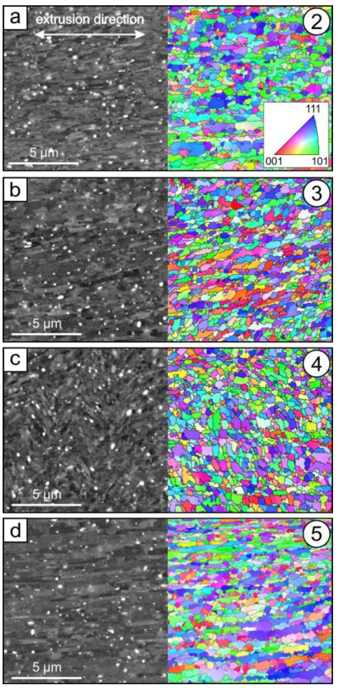
In
Figure 7, a more detailed microstructural investigation of the fine-grained surface area is presented. SEM images and color-coded orientation maps from EBSD measurements of Points 2–5 are shown; the corresponding extrusion direction is highlighted in
Figure 7a. Note that representative SEM images and the corresponding EBSD maps are taken from the same region but not from exactly the same area. With the help of the EBSD measurements, mean grain sizes and grain shape aspect ratios for the investigated points were derived (
Table 3). Note that the white speckles in the SEM images are typical Fe-/Mn-rich precipitates [
39] and are not further considered here.
Figure 7a corresponds to the surface area at Point 2. As discussed earlier, a grain refinement due to SPD processing can be observed and the initially coarse-grained surface layer has been fully refined. The initial material at Point 1 exhibits an average grain size of about 150 µm in the surface area and 10.2 ± 2.3 µm in the interior region (see
Table 3). The grain size at Point 2 is of ultrafine-grained (UFG) type with 0.79 ± 0.24 µm, and is homogeneously distributed. This result highlights that gradation extrusion is an effective process to provide the formation of numerous high-angle grain boundaries, resulting in a UFG microstructure. Note that the standard deviation of the grain size for all investigated locations is between 20 and 30% of the measured grain size, which is a characteristic value not originating from an uncertainty of the measurement but from the typical distribution of the grain size of SPD-processed materials. The corresponding grain shape (aspect ratio 2.7, see
Table 3) remains almost unaffected compared with that in the initial structure (aspect ratio 3.0) since gradation extrusion introduces a shear deformation which also results in elongated grains.
Figure 7b shows the microstructure of the near-surface area at Point 3. The average grain size (0.60 ± 0.18) has been slightly reduced compared with the grain size at Point 2. Furthermore, the aspect ratio of the grains has also been slightly reduced to 2.5, indicating that the fraction of grains originating from the transformation of equiaxed dislocation cells into high-angle boundaries is increased.
The microstructure of the surface area at Point 4 (see
Figure 7c) shows further changes: the former arrangement of elongated grains (see also
Figure 6c,e) in the extrusion direction cannot be observed anymore. An ultrafine deformation microstructure with a grain size of 0.51 ± 0.16 µm can be observed with an aspect ratio of 2.1, which is slightly lower compared to those at Point 3. Interestingly, localized plastic deformation occurred at this stage. The corresponding SEM image reveals distinct shear localization and the presence of shear bands (see also
Figure 8).
Figure 7d shows the microstructure of the near-surface area at Point 5, which represents the condition after the final reduction of the gradation extrusion. This final reduction leads again to an elongation of the grains parallel to the pressing direction. As a consequence of this extrusion step, the aspect ratio increases to 2.9. This is almost similar to the initial material, but compared to the initial material, the final grain size is significantly lower (0.66 ± 0.20 µm).
Figure 8 shows a SEM micrograph of a heterogeneously deformed region (see also
Figure 7c). The alignment of elongated ultrafine grains (see dashed line in
Figure 8) reveals the presence of two distinct band-like regions that have a width of several microns. An alternating arrangement of severely sheared regions next to regions with less strain is observed. These regions of localized straining are known to often act as initiation sites for cracking during further severe plastic deformation [
40,
41]. The absence of cracks in the billets after gradation extrusion indicates that microstructural gradients may also be beneficial in suppressing billet failure by shear localization.

 ,
, 


