Five-Axis Milling of Large Spiral Bevel Gears: Toolpath Definition, Finishing, and Shape Errors


Abstract
:1. Introduction
2. Integrated Rough-Finishing Approach
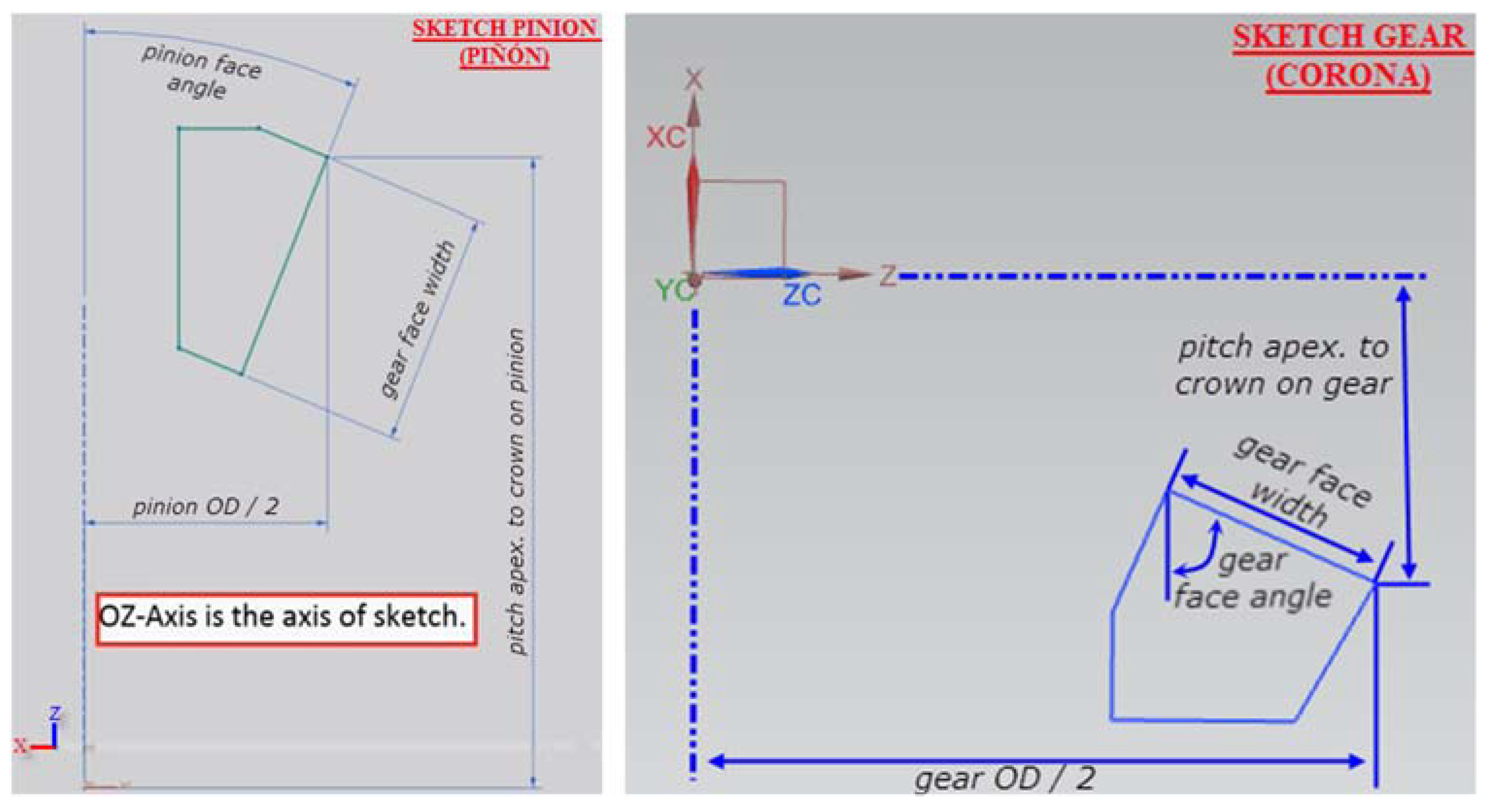
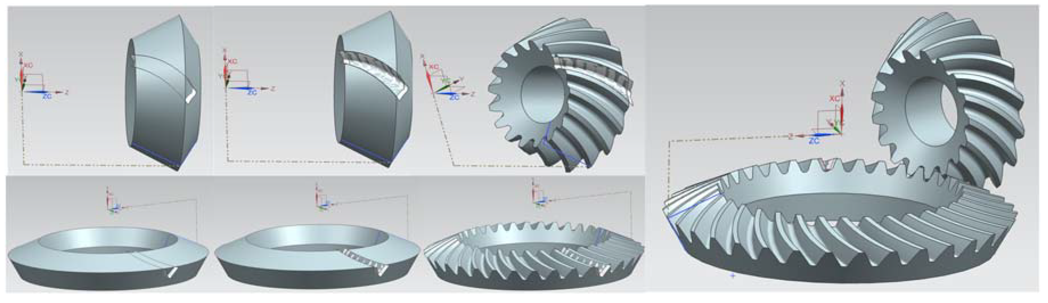
2.1. Design: CAD Step
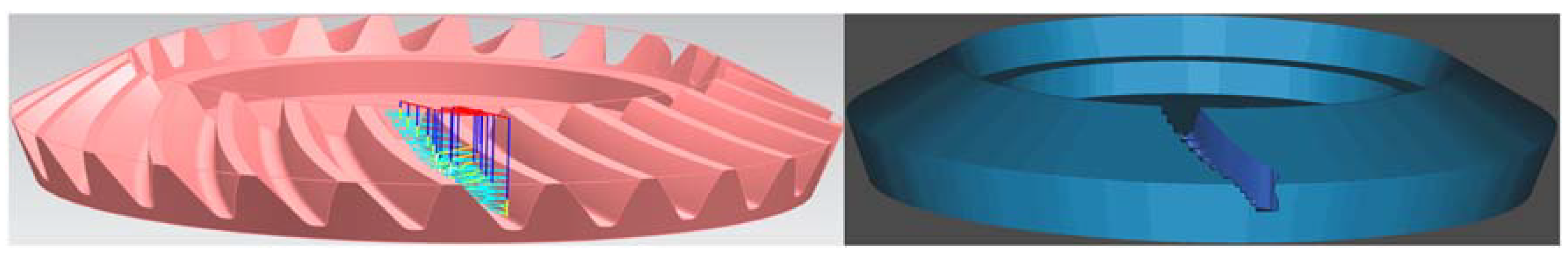
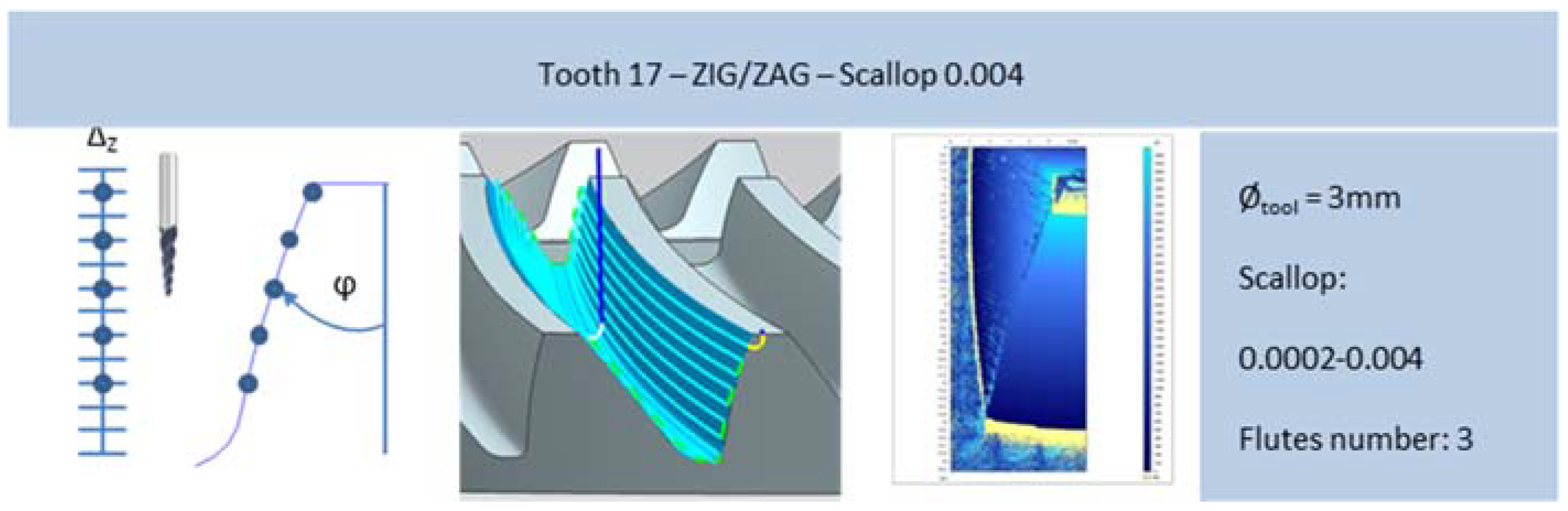
2.2. Manufacturing Trajectories Design: CAM Step
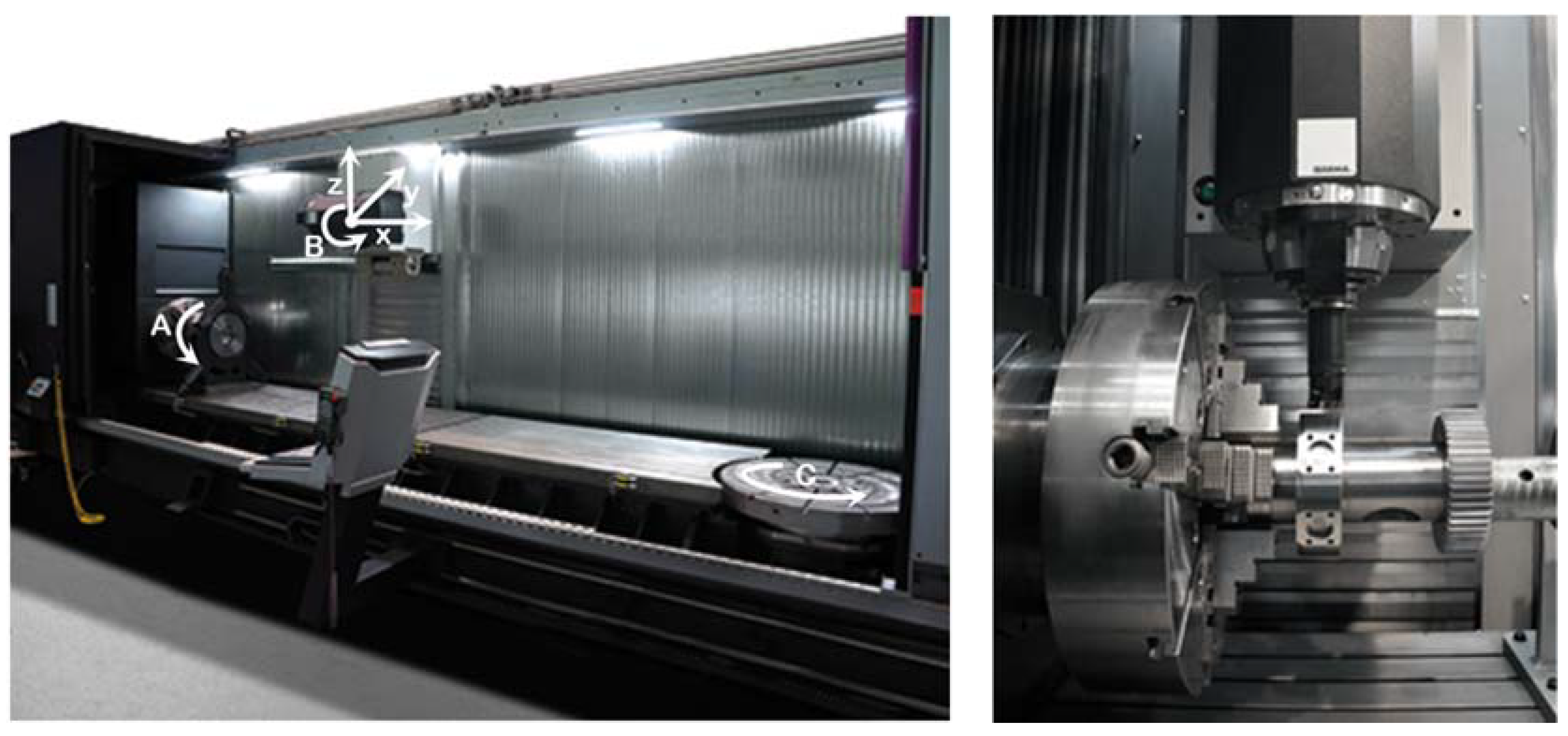
2.3. Experimental Set Up: Multiprocess Machine
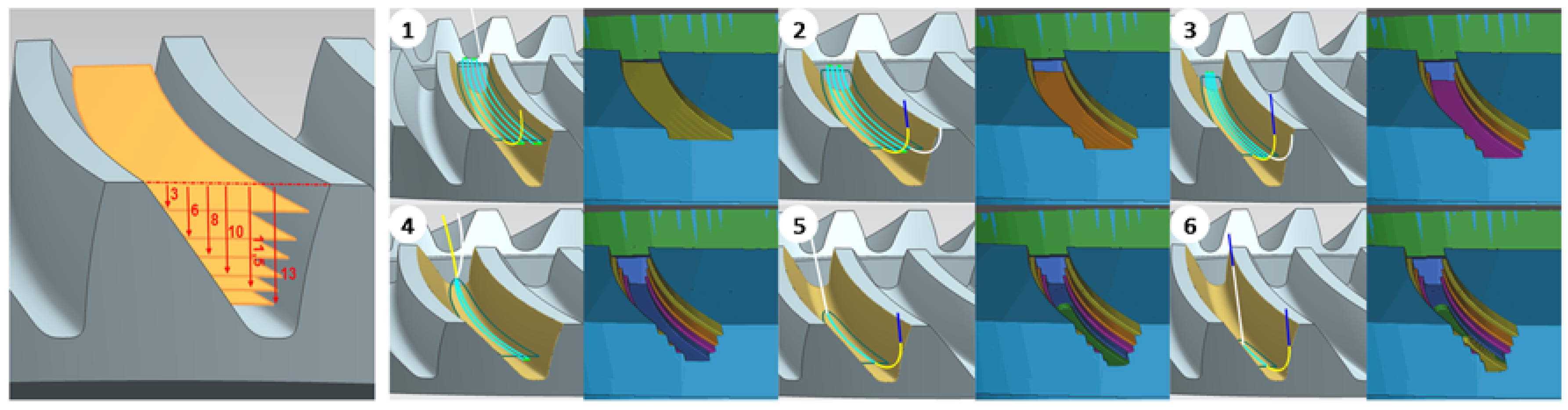
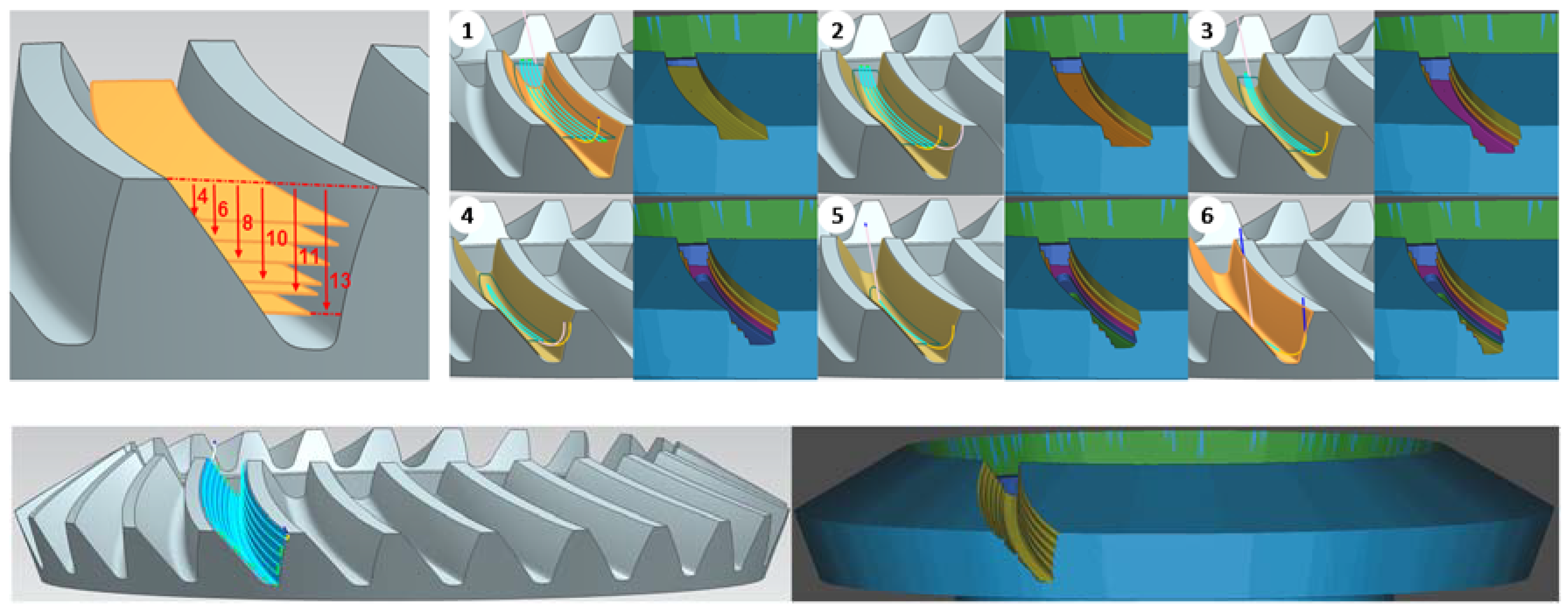
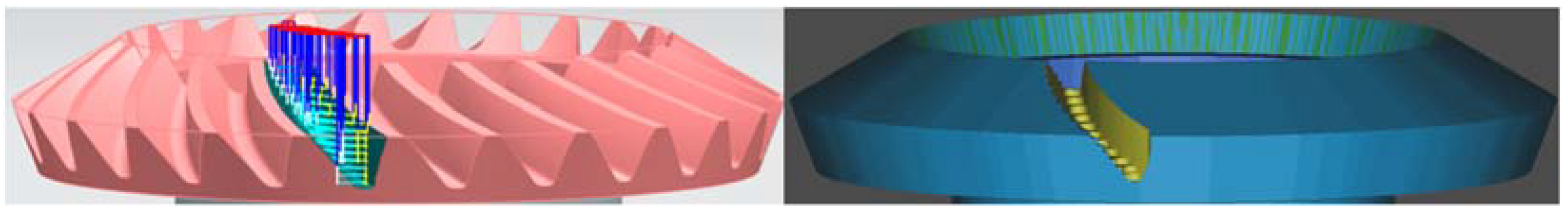
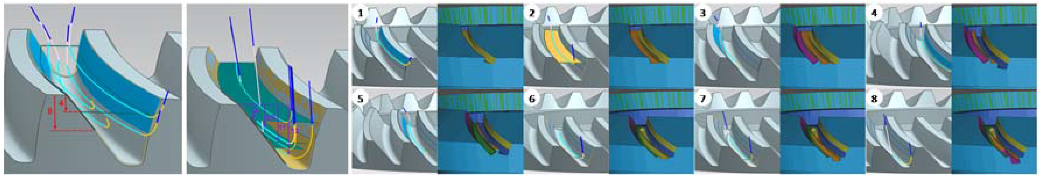
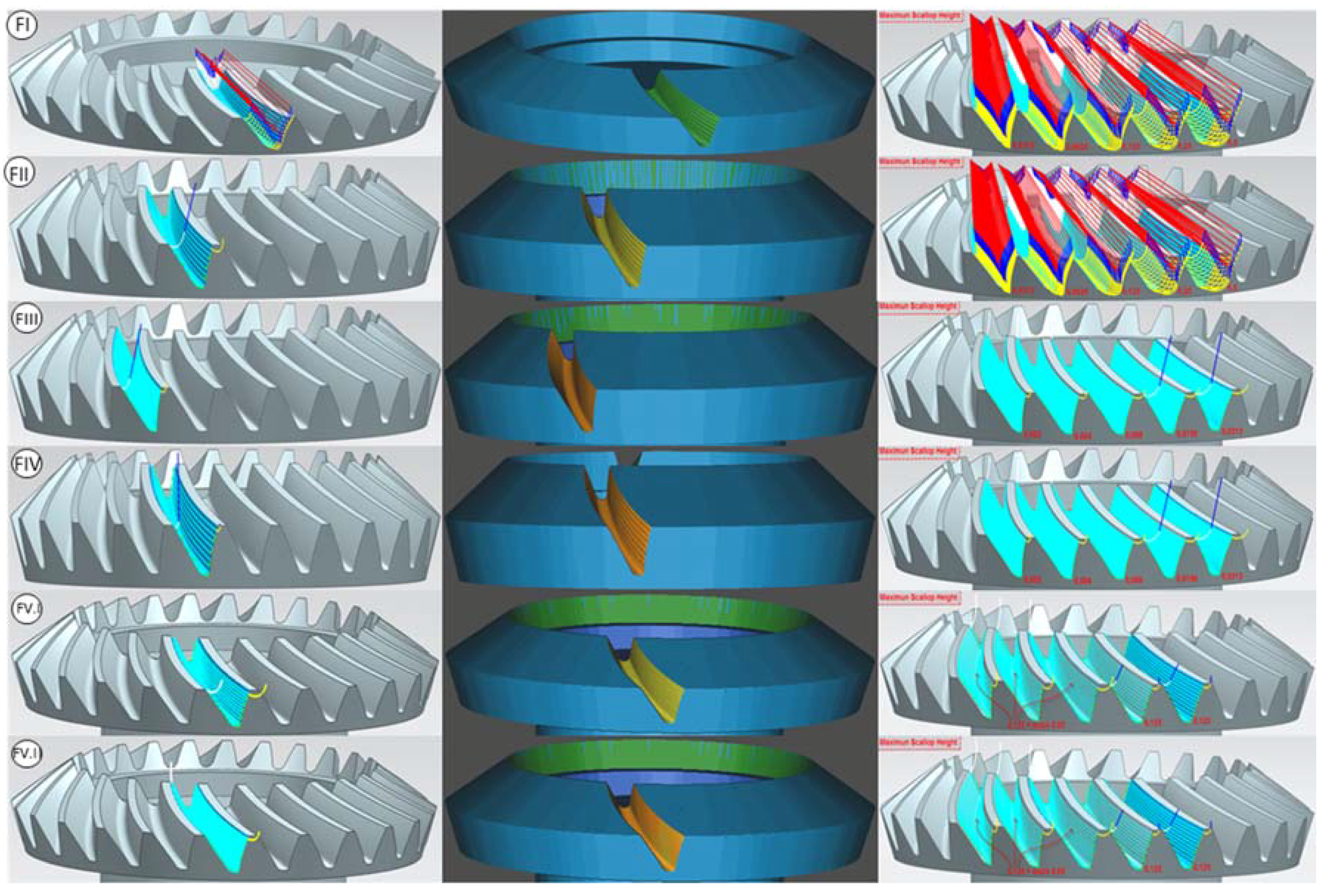
2.4. Integrated Roughing–Semifinishing–Finishing Approach
2.5. Machining
3. Results
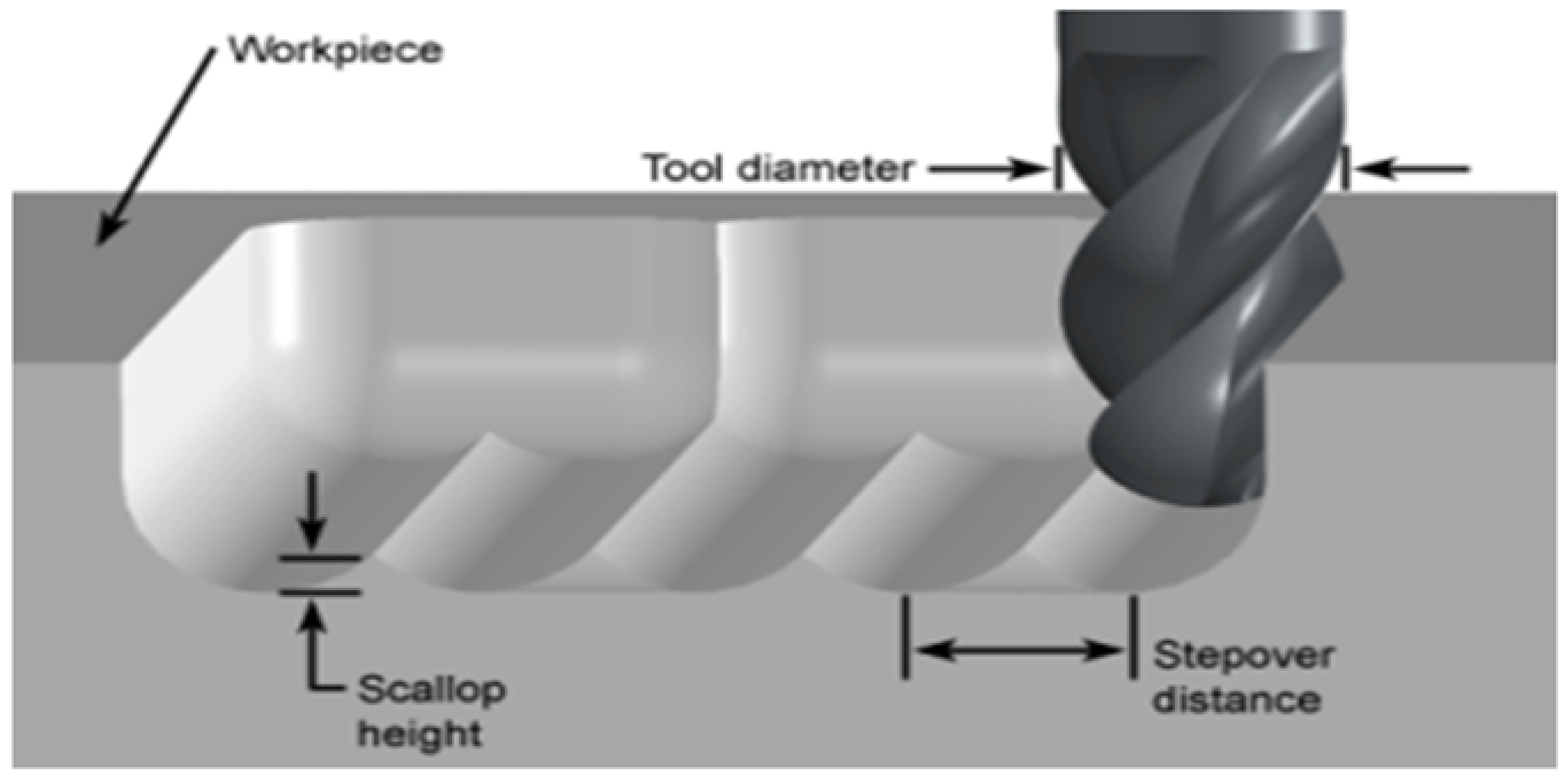
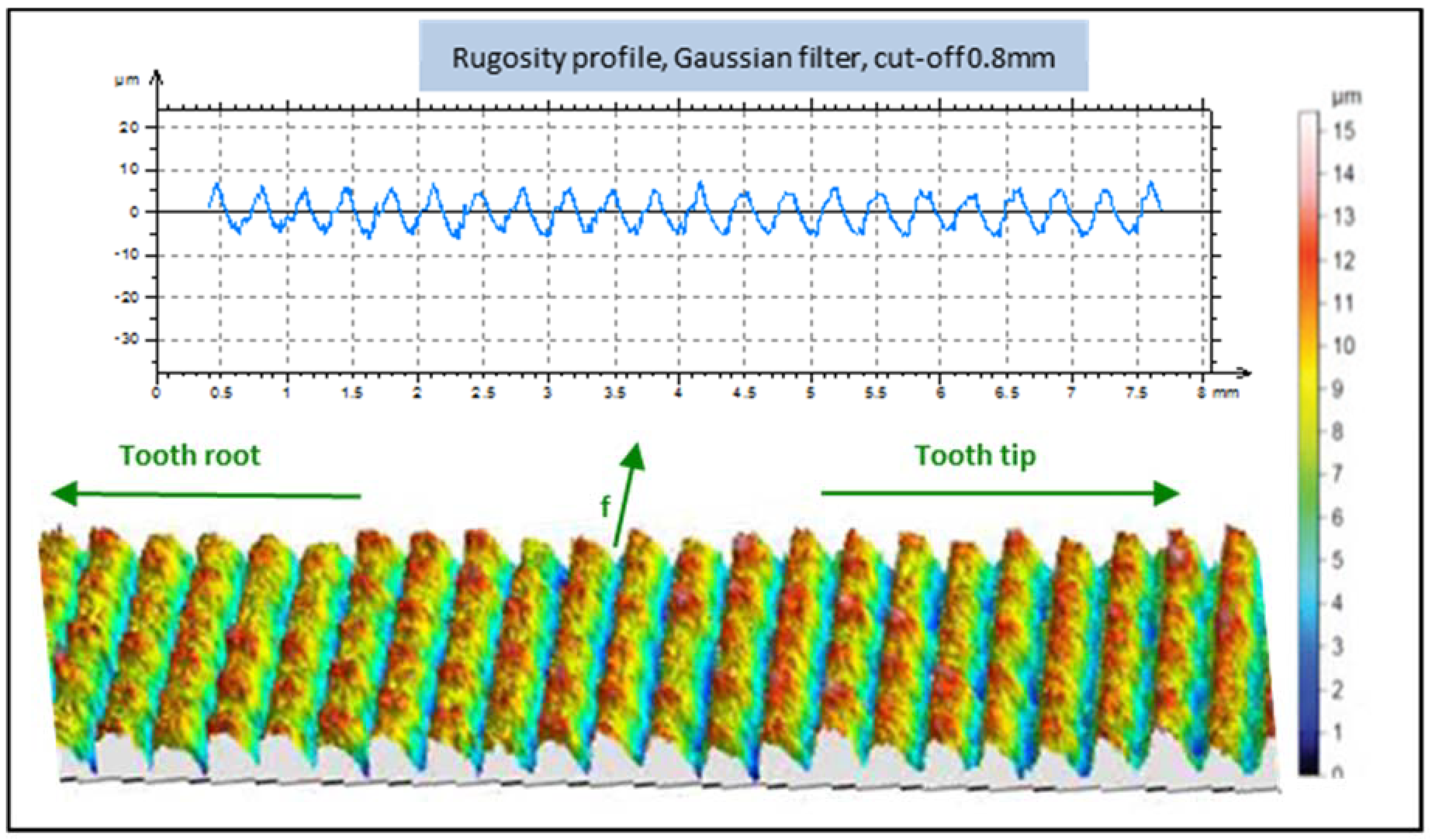
3.1. Roughness Analysis
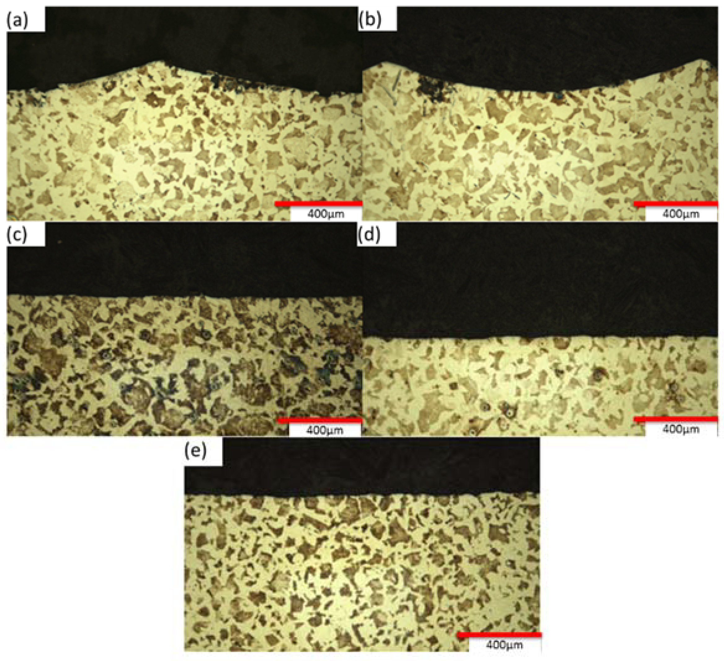
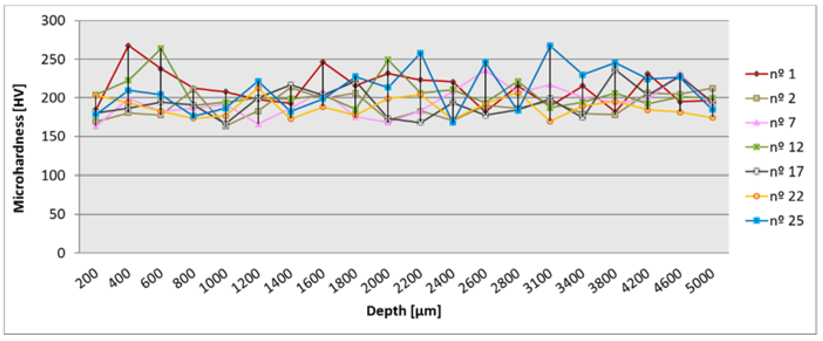
3.2. Surface Integrity
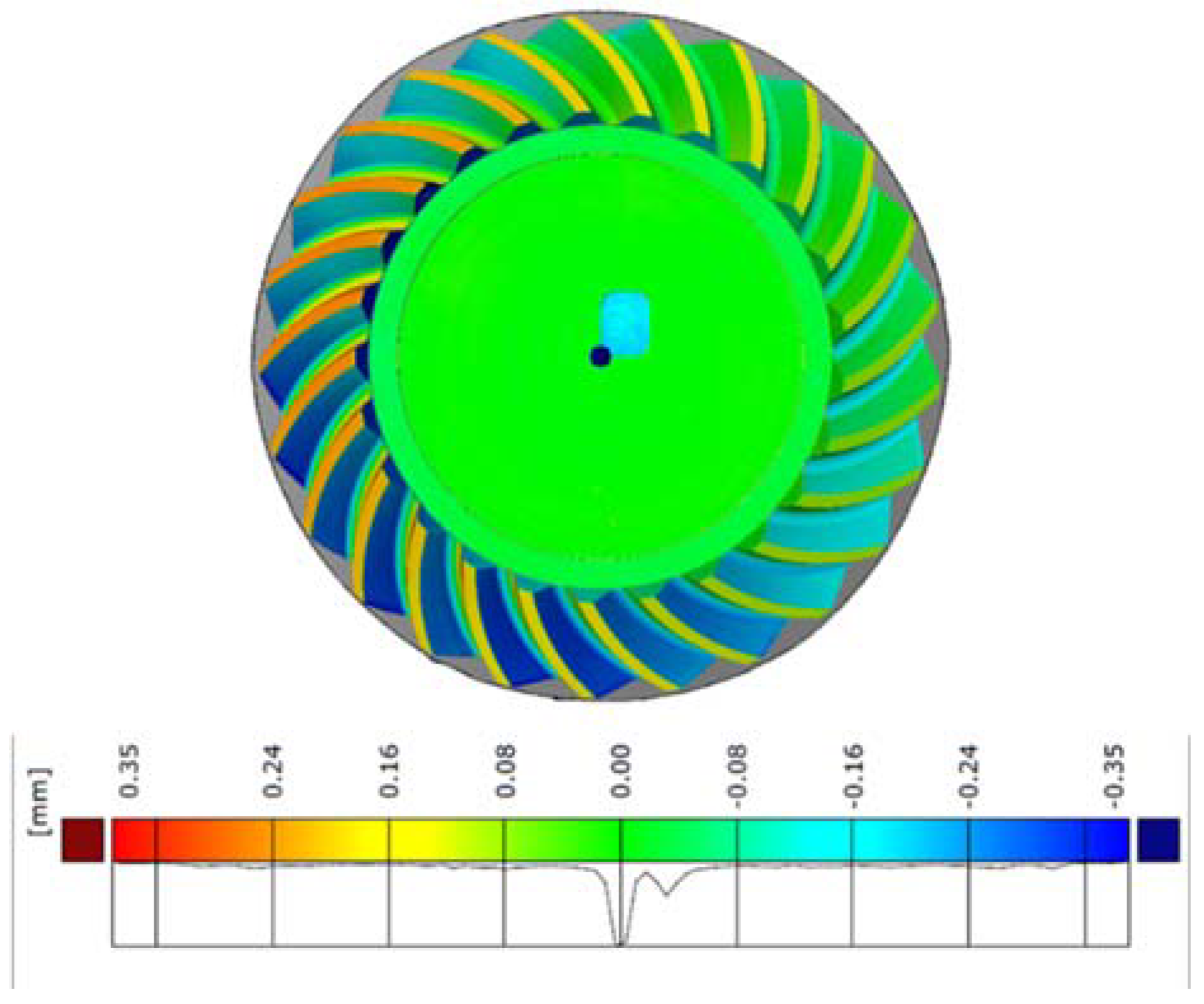
3.3. Form Deviation
3.4. Pitch Deviation
4. Discussion
5. Conclusions
Author Contributions
Funding
Acknowledgments
Conflicts of Interest
References
- Qin, Z.; Luo, Y.; Li, K.; Peng, H. Optimal design of a novel hybrid Electric powertrain for tracked vehicles. Energies 2017, 10, 2141. [Google Scholar] [CrossRef]
- Xu, G.; Hua, D.; Dai, W.; Zhang, X. Design and performance analysis of a coal bed gas drainage machine based on incomplete non-circular gears. Energies 2017, 10, 1933. [Google Scholar] [CrossRef]
- Stadtfeld, H.J. Gleason Bevel Gear Technology: The Science of Gear Engineering and Modern Manufacturing Methods for Angular Transmissions; Gleason Works: Rochester, NY, USA, 2014; ISBN 9780615964928. [Google Scholar]
- Watson, H.J. Gear Milling. In Modern Gear Production; Elsevier: New York, NY, USA, 1970; Chapter 8; pp. 146–158. ISBN 9780080158358. [Google Scholar]
- Lechner, G. Klingelnberg spiral bevel gears. J. Mech. 1968, 3, 217–218. [Google Scholar] [CrossRef]
- Zhuang, W.; Hua, L.; Han, X.; Zheng, F. Design and hot forging manufacturing of non-circular spur bevel gear. Int. J. Mech. Sci. 2017, 133, 129–146. [Google Scholar] [CrossRef]
- Calleja, A.; Gonzalez, H.; Polvorosa, R.; Ortega, N.; Lopez-de-Lacalle, L.N. Multitasking machines: evolution, resources, processes and scheduling. DYNA 2017, 92, 637–642. [Google Scholar] [CrossRef]
- Suh, S.H.; Jih, W.S.; Hong, H.D.; Chung, D.H. Sculptured surface machining of spiral bevel gears with CNC milling. Int. J. Mach. Tool Manuf. 2001, 41, 833–850. [Google Scholar] [CrossRef]
- Kawasaki, K.; Tsuji, I.; Abe, Y.; Gunbara, H. Manufacturing method of large-sized spiral bevel gears in cyclo-palloid system using multi-axis control and multi-tasking machine tool. In Proceedings of the International Conference on Gears, Garching, Germany, 4–6 October 2010; pp. 56–61. [Google Scholar]
- Uzun, M. The investigation on manufacturing time of a new type concave-convex gear by a CNC milling machine. Int. J. Adv. Manuf. Technol. 2015, 77, 1275–1280. [Google Scholar] [CrossRef]
- González, H.; Calleja, A.; Pereira, O.; Ortega, N.; López de Lacalle, L.N.; Barton, M. Super abrasive machining of integral rotary components using grinding flank tools. Metals 2018, 8, 24. [Google Scholar] [CrossRef]
- Gupta, K.; Jain, N.K.; Laubscher, R. Manufacturing of conical and noncircular gears. In Advanced Gear Manufacturing and Finishing; Academic Press: Cambridge, MA, USA, 2017; Chapter 3; pp. 53–66. [Google Scholar]
- Li, J.-B.; Ma, H.J.; Deng, X.Z. An approach to realize the networked closed-loop manufacturing of spiral bevel gears. Int. J. Adv. Manuf. Technol. 2017, 89, 1469–1483. [Google Scholar] [CrossRef]
- Rego, R.; Löpenhaus, C.; Gomes, J.; Klocke, F. Residual stress interaction on gear manufacturing. J. Mater. Process. Technol. 2018, 252, 249–258. [Google Scholar] [CrossRef]
- Gupta, K.; Laubscher, R.F.; Davim, J.P.; Jain, N.K. Recent developments in sustainable manufacturing of Gears: A review. J. Clean. Prod. 2016, 112, 3320–3330. [Google Scholar] [CrossRef]
- Lin, C.; Cheng, K.; Qin, D.; Guo, Q.; Zhou, P.; Qiu, H. An investigation on high-speed dry gear hobbing. Int. J. Mach. Mach. Mater. 2011, 9, 35–46. [Google Scholar] [CrossRef]
- Klocke, F.; Brumm, M.; Staudt, J. Quality and surface of gears manufactured by free form milling with standard tools. In Proceedings of the International Gear Conference, Lyon, France, 26–28 August 2014; pp. 506–515, ISBN 9781782421948. [Google Scholar] [CrossRef]
- Dudás, I.; Bodzás, S.; Dudás, I.S.; Mándy, Z. Development of spiroid worm gear drive having arched profile in axial section and a new technology of spiroid worm manufacturing with lathe center displacement. Int. J. Adv. Manuf. Technol. 2015, 79, 1881–1892. [Google Scholar] [CrossRef]
- Lin, C.; Fan, Y.; Zhang, Z. Additive manufacturing with secondary processing of curve-face gears. Int. J. Adv. Manuf. Technol. 2016, 86, 9–20. [Google Scholar] [CrossRef]
- Li, Z.; Wang, B.; Ma, W. Comparison of ironing finishing and compressing finishing as post-forging for net-shape manufacturing. Int. J. Adv. Manuf. Technol. 2016, 86, 3333–3343. [Google Scholar] [CrossRef]
- Hyatt, G.; Piber, M.; Chaphalkar, N.; Kleinhenz, O.; Mori, M. A Review of new strategies for gear production. Procedia CIRP 2014, 14, 72–76. [Google Scholar] [CrossRef]
- Bouquet, J.; Hensgen, L.; Klink, A.; Jacobs, T.; Klocke, F.; Lauwers, B. Fast production of gear Prototypes—A comparison of technologies. Procedia CIRP 2014, 14, 77–82. [Google Scholar] [CrossRef]
- Bae, I.; Schirru, V. An approach to find optimal topological modification to duplicate tooth flank form of the existing Gear. In Proceedings of the International Gear Conference, Lyon, France, 26–28 August 2014; pp. 34–43. [Google Scholar]
- 3-D Mathematical Modeling of Geared Mechanical Systems. Available online: http://www.spiralbevel.com/ (accessed on 1 May 2018).
- Fuentes, A.; Ruiz-Orzaez, R.; Gonzalez-Perez, I. Computerized design, simulation of meshing, and finite element analysis of two types of geometry of curvilinear cylindrical gears. Comput. Methods Appl. Mech. Eng. 2014, 272, 321–339. [Google Scholar] [CrossRef]
- Tang, J.; Yang, X. Research on manufacturing method of planning for spur face-gear with 4-axis CNC planer. Int. J. Adv. Manuf. Technol. 2016, 82, 847–858. [Google Scholar] [CrossRef]
- Calleja, A.; Alonso, M.A.; Fernández, A.; Tabernero, I.; Ayesta, I.; Lamikiz, A.; López de Lacalle, L.N. Flank milling model for tool path programming of turbine blisks and compressors. Int. J. Prod. Res. 2014, 53, 3354–3369. [Google Scholar] [CrossRef]
- López de Lacalle, L.N.; Lamikiz, A.; Sánchez, J.A.; de Bustos, I.F. Recording of real cutting forces along the milling of complex parts. Mechatronics 2006, 16, 21–32. [Google Scholar] [CrossRef]
- Malkin, S.; Guo, C. Thermal Analysis of grinding. Ann. CIRP 2007, 56, 760–782. [Google Scholar] [CrossRef]
- Kundrák, J.; Markopoulos, A.P.; Zarkalos, N.E. Numerical simulation of grinding with realistic representation of grinding wheel and workpiece Movements: A finite volumes study. Procedia CIRP 2017, 58, 275–280. [Google Scholar] [CrossRef]
- Ortega, N.; Alonso, U.; Sánchez, J.A.; Pombo, I.; Plaza, S.; Izquierdo, B. Modelling of the hardening and finishing stages of grind-hardened workpieces. Int. J. Adv. Manuf. Technol. 2016, 82, 435–449. [Google Scholar] [CrossRef]


| Standard | Grade | C | Mn | P | S | Si | Cr | Mo |
|---|---|---|---|---|---|---|---|---|
| EN 10084 | 18CrMo4/1.7243 | 0.15–0.21 | 0.60–0.90 | 0.025 | 0.035 | 0.9–1.2 | 0.9–1.2 | 0.15–0.25 |
| Step 1: Input Preliminary Data | |
| Gear heel pitch diameter (mm) | 200 |
| Ratio (pinion rmp/gear rpm) | 2 |
| Hand of spiral (left or rigth) | LEFT |
| Step 2: Finalize Data. Run ‘Gear’ ‘Pinion’ | |
| Shaft angle | 90 |
| Number of teeth on gear | 34 |
| Number of teeth on pinion | 17 |
| Gear face width (mm) | 34 |
| Preassure angle (deg) | 20 |
| Spiral angle (deg) | 35 |
| Gear transversal tooth thickness on heel (mm) | 9 |
| Angular blacklash gear (deg) | 0.15 |
| Gear coef. of addendum | 1 |
| Coef. of tooth height | 2.25 |
| Face cutter generating diameter (mm) | 140 |
| Profile crowning (mm) | 0.005 |
| Lead crowning (mm) | 0.002 |
| Coef. root radial clearance | 0.25 |
| Output | |
| Gear face angle (deg) | 66.37533996 |
| Pinion face angle (deg) | 29.64876178 |
| Pinion od (mm) | 108.947 |
| Gear od (mm) | 204.435 |
| Pitch apex to crown on pinion (mm) | 97.763 |
| Pitch apex to crown on gear (mm) | 45.564 |
| Root clearance (mm) | 0.783 |
| Pinion heel pitch diameter (mm) | 100 |
| Pinion transversal tooth thickness on heel (mm) | 9.218 |
| Face cutter radial distance (mm) | 79.214 |
| Feed (mm/min) | Speed (rpm) | Depth of Cut Per Pass (mm) | Cutting Fluid |
|---|---|---|---|
| 230 | 9550 | 0.5 | Conventional oil and water emulsion coolant |
| Roughing Strategy | Tooth Number | Machining Time | |
|---|---|---|---|
| R-I | Cavity mill (3 + 1-axis) Follow periphery | 1, 2, 3, 4, 5 | 5′11′′ |
| R-II | Variable contour (5-axis) Stream line | 6, 7, 8, 9, 10 | 4′15′′ |
| R-III | Variable contour (5-axis) Stream line | 11, 12, 13, 14, 15 | 3′54′′ |
| R-IV | Variable contour (5-axis) Surface area + Stream line | 16, 17, 18, 19, 20 | 2′ |
| R-V | Cavity mill (3 + 1-axis) Throchoidal | 21, 22, 23, 24, 25 | 11′42′′ |
| Finishing Strategy | Tooth Number (Groove) | Machining Time | |
|---|---|---|---|
| F-I | Surface area + relative vector Cut pattern zig(1,3)-zig/zag(2,4,5) (Scallop 0.004-0.004-0.002-0.002-0.002) | 1 | 8′58′′ |
| 2 | 4′31′′ | ||
| 3 | 12′59′′ | ||
| 4 | 6′24′′ | ||
| 5 | 6′24′′ | ||
| F-II | Surface area + relative vector Cut pattern zig(6,8)-zig/zag(7,9,10) (Scallop 0.004-0.004-0.002-0.002-0.002) | 6 | 8′58′′ |
| 7 | 4′31′′ | ||
| 8 | 12′59′′ | ||
| 9 | 6′24′′ | ||
| 10 | 6′24′′ | ||
| F-III | Surface area + relative vector Cut pattern zig(11,13)-zig/zag(12,14,15) (Scallop 0.004-0.004-0.002-0.002-0.002) | 11 | 11′58′′ |
| 12 | 6′53′′ | ||
| 13 | 16′40′′ | ||
| 14 | 9′45′′ | ||
| 15 | 9′45′′ | ||
| F-IV | Surface area + relative vector Cut pattern zig(16,18)-zig/zag(17,19,20) (Scallop 0.004-0.004-0.002-0.002-0.002) | 16 | 8′58′′ |
| 17 | 4′31′′ | ||
| 18 | 12′59′′ | ||
| 19 | 6′24′′ | ||
| 20 | 6′24′′ | ||
| F-V.1 F-V.2 | Surface area + relative vector Cut pattern: zig/zag (Scallop 0.125) | 21 | 4′48′′ |
| 22 | 2′35′′ | ||
| 23 | 4′48′′ | ||
| 24 | 2′35′′ | ||
| 25 | 24′ | ||
| Finishing Strategy Group | 1 | 2 | 3 | 4 | 5 | ||||||||||||||||||||
|---|---|---|---|---|---|---|---|---|---|---|---|---|---|---|---|---|---|---|---|---|---|---|---|---|---|
| Tooth Number | 1 | 2 | 3 | 4 | 5 | 6 | 7 | 8 | 9 | 10 | 11 | 12 | 13 | 14 | 15 | 16 | 17 | 18 | 19 | 20 | 21 | 22 | 23 | 24 | 25 |
| Ra | 1.0 | 2.9 | 1.4 | 1.8 | 2.2 | 1.3 | 2.9 | 1.1 | 1.8 | 1.9 | 0.7 | 2.5 | 0.5 | 1.5 | 1.6 | 0.8 | 2.2 | 0.6 | 1.1 | 1.1 | 2.0 | 2.6 | 2.2 | 2.8 | 0.8 |
| Rz | 4.9 | 10.9 | 11.7 | 8.2 | 8.8 | 7.0 | 11.9 | 8.1 | 9.5 | 9.6 | 3.7 | 10.3 | 2.9 | 7.2 | 7.2 | 4.3 | 9.5 | 3.3 | 5.3 | 5.3 | 11.8 | 14.8 | 11.7 | 14.4 | 4.5 |
© 2018 by the authors. Licensee MDPI, Basel, Switzerland. This article is an open access article distributed under the terms and conditions of the Creative Commons Attribution (CC BY) license (http://creativecommons.org/licenses/by/4.0/).
Share and Cite
Álvarez, Á.; Calleja, A.; Ortega, N.; De Lacalle, L.N.L. Five-Axis Milling of Large Spiral Bevel Gears: Toolpath Definition, Finishing, and Shape Errors. Metals 2018, 8, 353. https://doi.org/10.3390/met8050353
Álvarez Á, Calleja A, Ortega N, De Lacalle LNL. Five-Axis Milling of Large Spiral Bevel Gears: Toolpath Definition, Finishing, and Shape Errors. Metals. 2018; 8(5):353. https://doi.org/10.3390/met8050353
Chicago/Turabian StyleÁlvarez, Álvaro, Amaia Calleja, Naiara Ortega, and Luis Norberto López De Lacalle. 2018. "Five-Axis Milling of Large Spiral Bevel Gears: Toolpath Definition, Finishing, and Shape Errors" Metals 8, no. 5: 353. https://doi.org/10.3390/met8050353
APA StyleÁlvarez, Á., Calleja, A., Ortega, N., & De Lacalle, L. N. L. (2018). Five-Axis Milling of Large Spiral Bevel Gears: Toolpath Definition, Finishing, and Shape Errors. Metals, 8(5), 353. https://doi.org/10.3390/met8050353