Abstract
The formation of nanocrystalline structures in bulk metal materials is of great significance for both investigating the structural features of nanocrystalline materials and enhancing the value of bulk metal materials in engineering applications. Herein, we report a nanocrystalline structure formed by lattice transformation in a three-dimensional bulk metal material. We characterized its phase composition, three-dimensional features, and boundary structure. This nanocrystalline structure had microscale length and height and nanoscale width, which gave it a “nanoplate” structure in three-dimensional space. We observed edge dislocations in the interior of the nanocrystalline structure. A unique transitional boundary that contributed to maintaining its nanoscale size was found at the border between the parent phase and the nanocrystalline structure.
1. Introduction
Since the last century, nanomaterials have been extensively studied because of their outstanding mechanical and physical properties [1,2,3]. The use of both physical and chemical methods, such as gas-phase condensation [4] and electrodeposition [5,6], for the synthesis of such nanomaterials, have been reported in abundance. Nanomaterials include quantum dots and small nanoparticles (zero-dimensional) [7,8], nanotubes and nanowires (one-dimensional) [9,10], nanofilms and nanocoatings (two-dimensional) [11,12], and more complex structures (three-dimensional) [13]. However, bulk materials are still the dominant materials used for engineering applications.
It is well known that a nanocrystalline structure can be formed into three-dimensional bulk metals, greatly improving the performance and quality of such materials and thus increasing their applicability. Several methods of forming a nanocrystalline structure, such as crystallization of amorphous solids [14,15], severe plastic deformation (SPD) [16,17,18,19], and dynamic plastic deformation (DPD) [20], have been adopted. However, the above methods are complex and require a large amount of energy.
Recently, a nanoscale structure with a combination of extremely high strength and toughness was formed in a kind of high-carbon, silicon-containing steel by Bhadeshia et al. using austempering at a temperature slightly above the starting temperature of martensite phase transition over several tens of days [21,22,23,24]. This method effectively provides nanostructures by recombination of the atoms in a three-dimensional bulk metal system.
Herein, we explore a nanocrystalline structure formed in a bulk steel material that is adjustable through tailoring the transformation temperature and time. This method required less time and energy cost than ever before, and we present the structural characteristics of the material, especially the boundary characteristics of this nanocrystalline structure.
2. Experimental Details
2.1. Sample Preparation
The chemical composition of the experimental steel used in this study was similar to that of the high-carbon steels studied by Bhadeshia et al. [21]. To obtain a circular cone, Fe–1.01C–1.48Si–1.05Cr–0.44Mn–0.04Ni (wt%) was melted in a ZG-25 vacuum medium-frequency induction melting furnace (Zhonghuan Lab Furnace, Tianjin, China). After that, the ingot was forged into round bars with a diameter of 30 mm. Table 1 shows the chemical composition of the final sample measured using a SPECTROMAXx spectrometer (Ametek, San Diego, CA, USA). The homogenizing treatment for the samples was carried out in an argon-protective atmosphere at 1200 °C for 24 h.

Table 1.
Chemical composition of the experimental steel (wt%).
After heating in an argon atmosphere protection furnace to 950 °C and holding for 30 min, the samples were cooled to room temperature in two ways. One of the ways was to quickly transfer them from high temperature to molten salt (55% NaNO2 + 45% KNO3), then keep them at a constant temperature for 40 min (austempering), and finally put them into water to cool to room temperature. The other way was to directly cool the samples in the furnace to bring their temperature down to room temperature (annealing).
2.2. Characterization Techniques
The treated samples were etched in a 4% nitric acid alcohol solution after being mechanically ground and polished. The microstructure of the samples was observed using a Carl Zeiss Axio Scope A1 optical microscope (Carl Zeiss, Oberkochen, Germany).
The phase of the samples was analyzed by Rigaku D/Max-2500V X-ray diffractometer (Rigaku, Tokyo, Japan). The working parameters were Cu target Kα radiation, 40 kV operating voltage, and 100 mA operating current, and the scanning angle 2θ ranged from 30° to 90° with a scanning speed of 1°/min.
The samples prepared for the SEM analysis were deeply etched by the 4% nitric acid alcohol solution for 12 s. The analysis of the samples was performed using a Phenom Pro X scanning electron microscope (Phenom, Eindhove, The Netherlands).
The transmission electron microscopy (TEM) films, with a diameter of 3 mm and a thickness of 2 mm, were cut out from the heat-treated experimental material and mechanically ground to 30 μm in thickness on a waterproof abrasive paper. Then 20 V was applied at −20 °C using 5% perchloric acid and a 95% methanol (Aladdin, Shanghai, China) solution. The voltage was thinned by double injection until perforation, and thin film samples were prepared. Fine-structure analysis of the samples was performed using a FEI TECNAI G2 F20 transmission electron microscope (FEI, Hillsboro, OR, USA).
3. Results and Discussion
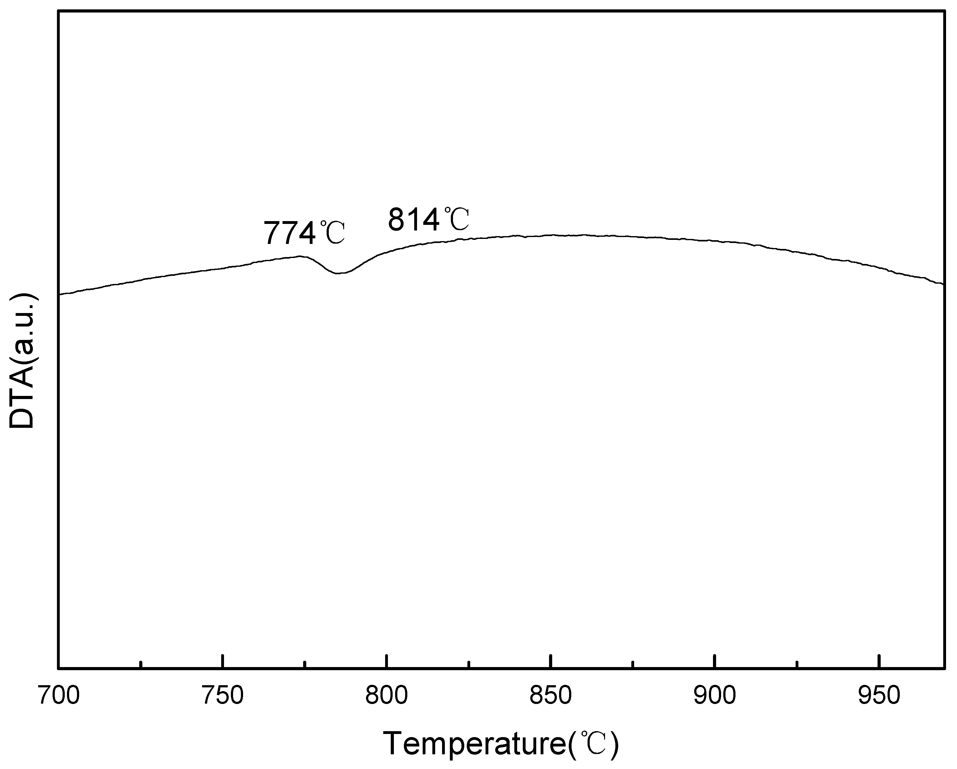
The enthalpy changes of the samples during the crystal lattice transition of the heating process were analyzed by a TG/DTA6300 analyzer (Netzsch, Frankfurt am Main, Germany). The DTA result is shown in Figure 1, the endothermic reaction, which marks the transition from body-centered cubic to face-centered cubic, was detected between 774 °C and 814 °C. The resulting material did not show significant endothermic or exothermic reactions above 814 °C, indicating that the samples were in a single γ-Fe lattice state at 814 °C and above [24].
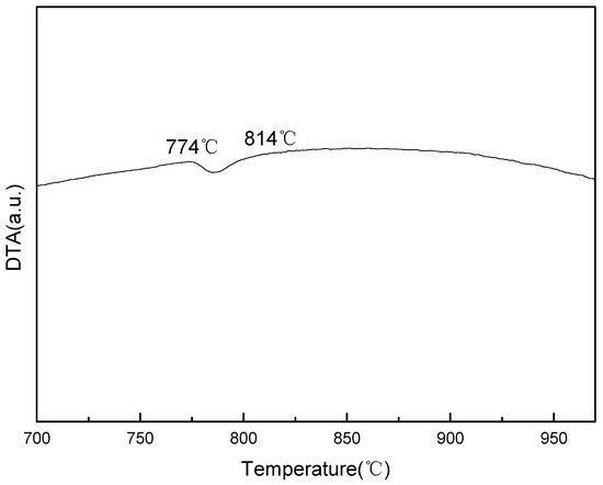
Figure 1.
Differential thermal analysis (DTA) curve of the samples during the heating process. The temperature interval of the lattice transformation is about 774 °C–814 °C.
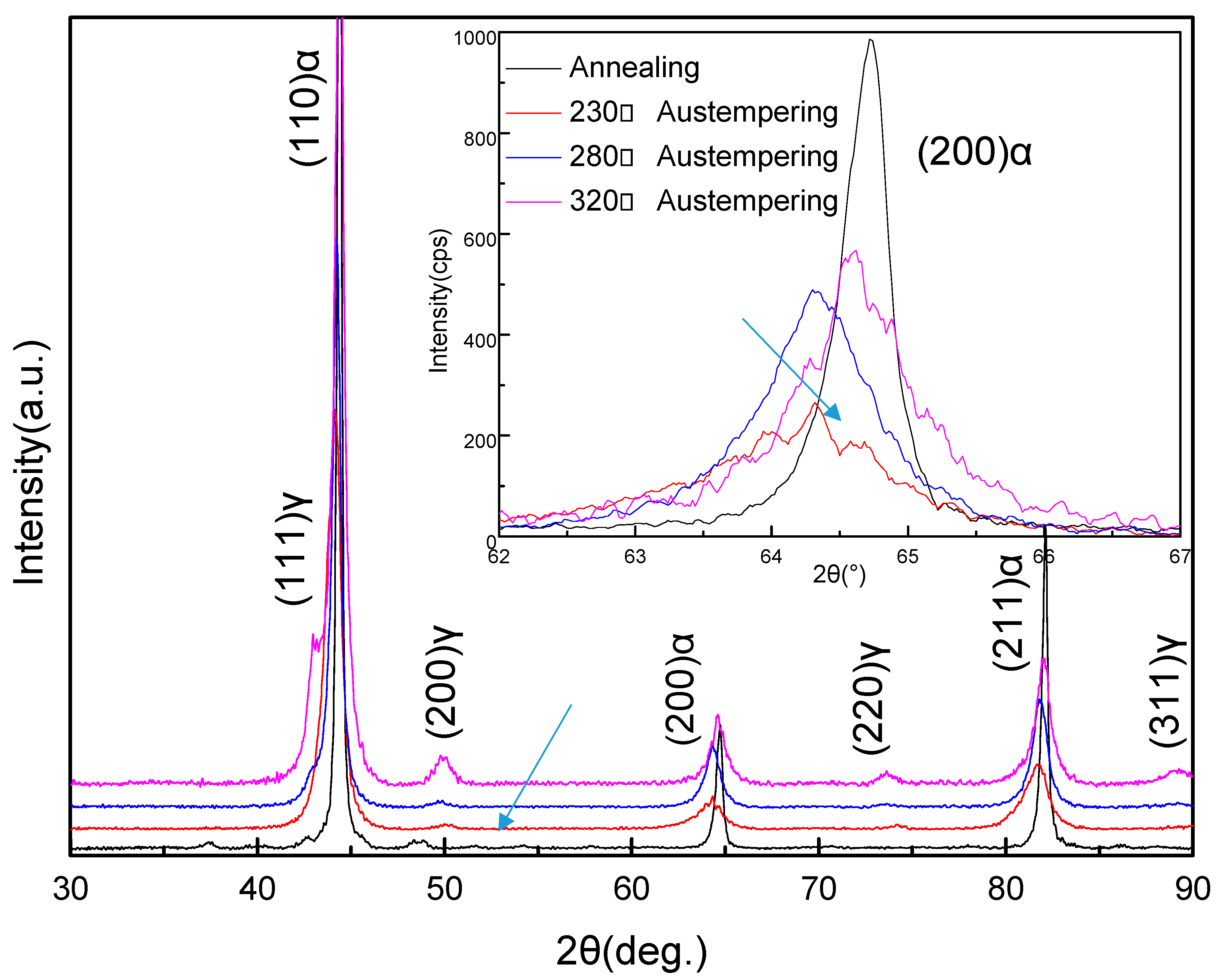
The XRD analysis of the samples that had been austempered at different temperatures after heating to 950 °C showed that the structure mainly consisted of fcc lattice (γ-Fe) and bcc lattice (α-Fe), as shown in Figure 2. It was evident that the γ-Fe phase was the residual parent phase, while the α-Fe phase was the new phase formed during the isothermal process. Compared with the annealed samples, the peaks of the α-Fe phase in the austempered samples, such as the peaks representing the (200) crystal plane of α-Fe, were more diffuse. On the basis of previous X-ray diffraction studies [25,26], this result means that the α-Fe phase formed smaller grains in the austempered samples. Compared to the other austempered samples, the diffraction peak representing the (200) plane of the α-Fe in the sample that was austempered at 230 °C was the widest and the lowest in intensity (indicated by the arrow). When the austempering temperature was increased to 280 °C, the width of the diffraction peak representing the (200) plane of α-Fe was slightly reduced but the intensity clearly increased. When the austempering temperature was increased to 320 °C, the (200) plane diffraction peak of α-Fe became more cuspidal. This showed that when the austempering time of the samples was the same, the increasing of the austempering temperature caused the α-Fe grains to grow. At lower austempering temperatures, the α-Fe grains were finer, but their total content was lower.
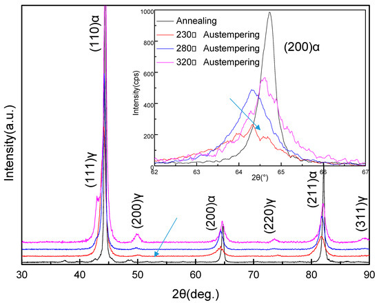
Figure 2.
X-ray diffraction (XRD) patterns of the samples after heat treatment. α and γ denote the α-Fe lattice phase and the γ-Fe lattice phase, respectively. The figure at top right shows the XRD peaks from the (200) plane of the α-Fe lattice phase by slow scanning.
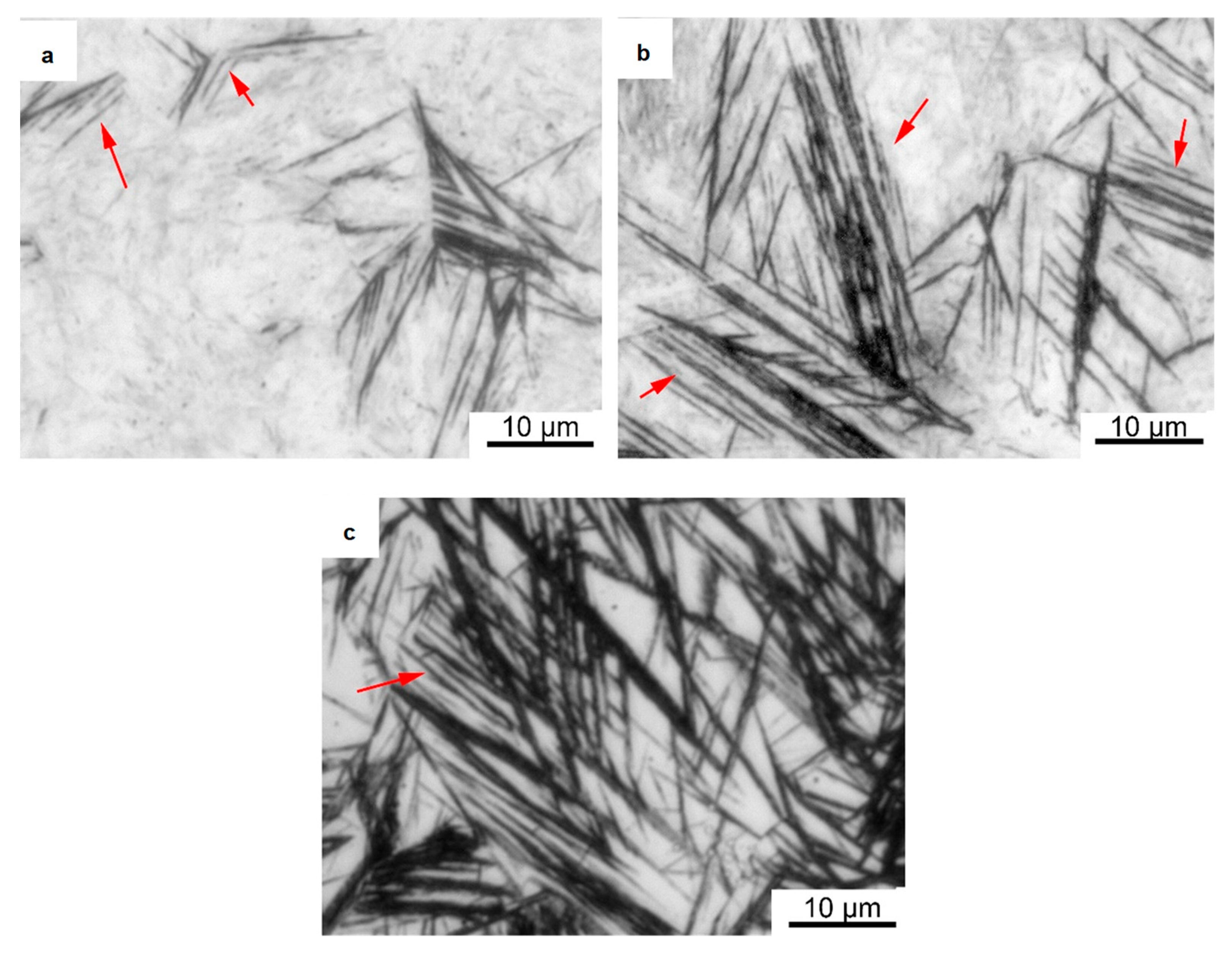
A substantial number of observations of the austempered samples were made using an optical microscope. It was found that a new phase consisting of extremely fine strips arranged in parallel was formed in the samples, as shown in Figure 3a–c. The length of each strip ranged from a few micrometers to tens of micrometers (indicated by the red arrows), and their widths were too small to measure using an optical microscope. The samples austempered at 230 °C showed the lowest number of paralleled strips. With an increase in the austempering temperature to 280 °C, these paralleled strips became significantly longer, but they remained extremely thin. When the austempering temperature reached 320 °C, the number of strips in the samples increased, and they became significantly wider. This result shows that when the austempering temperature exceeded 280 °C, the width of the strips could be increased. Based on quantitative metallography, we used the Proimaging software (Version 1.1, Carl Zeiss, Oberkochen, Germany) to analyze the amounts of this phase, and the results showed that the amounts of the bcc phase were 6%, 25%, and 36%, respectively. This is consistent with the previous XRD results.
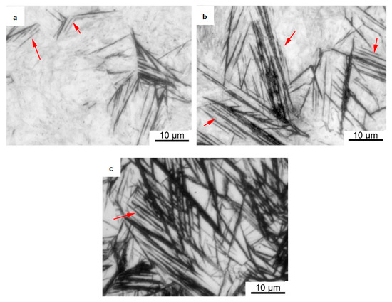
Figure 3.
Optical micrographs of samples austempered in molten salt. (a) Quenching at 230 °C; (b) Quenching at 280 °C; (c) Quenching at 320 °C.
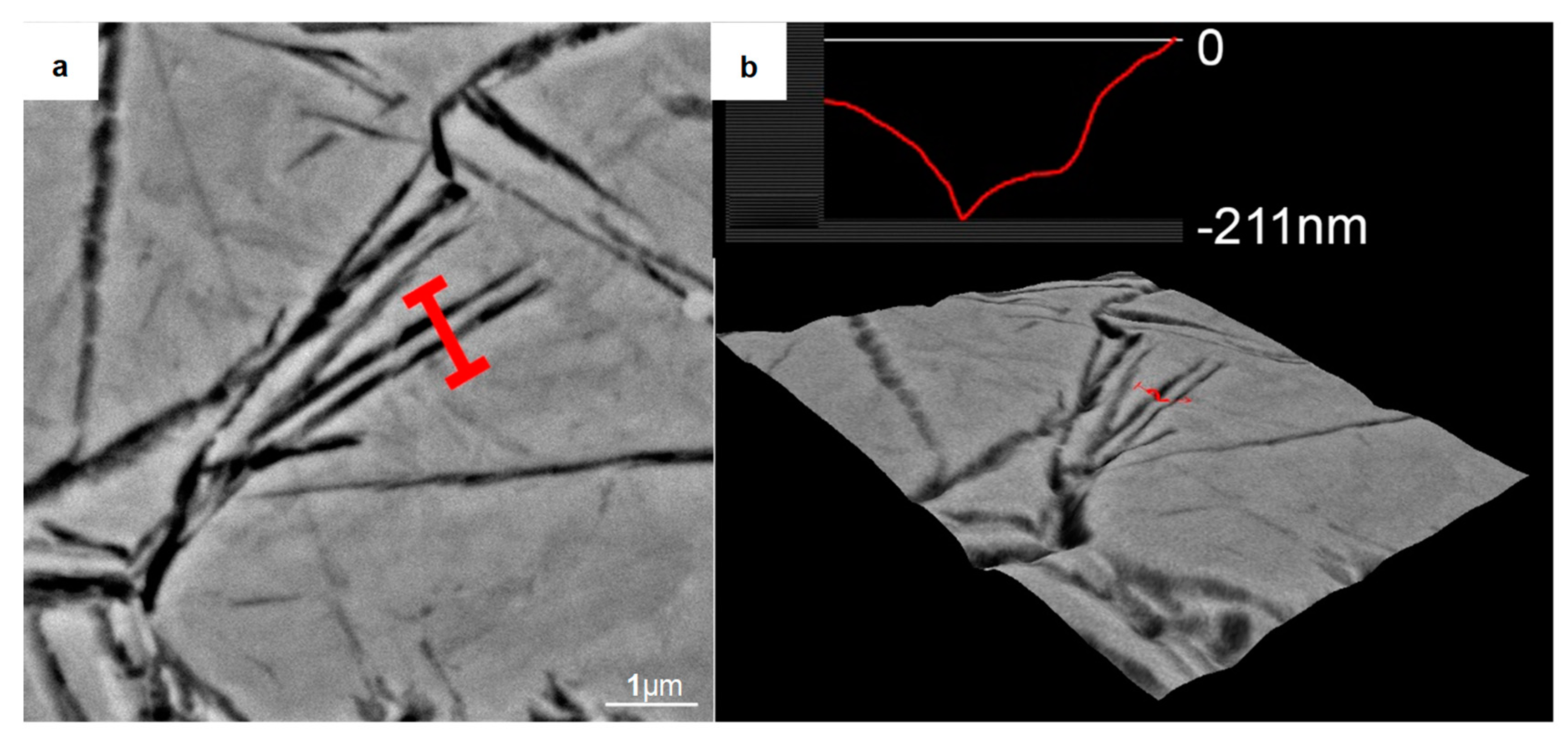
To further reveal the three-dimensional characteristics of these strips, we used a 4% nitric acid ethanol solution to etch the sample (austempered at 280 °C) for 12 s. A typical SEM micrograph of the corroded areas is shown in Figure 4. Parallel furrow-like structures were observed. The grooves were the α-Fe lattice phases, which were deeply eroded by the nitric acid solution, while the embossments were the remaining γ-Fe lattice phases [27]. Three-dimensional roughness analysis showed that the strips has a height of more than 200 nm.
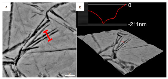
Figure 4.
Analysis of the nanocrystalline structure formed in the sample quenched at 280 °C after deep etching by a 4% nitric acid alcohol solution. (a) Backscattered electron image of the analysis area; (b) Size analysis by the 3D Roughness Reconstruction software. It indicates that the nanocrystalline structure had a size of about 200 nm in the height direction.
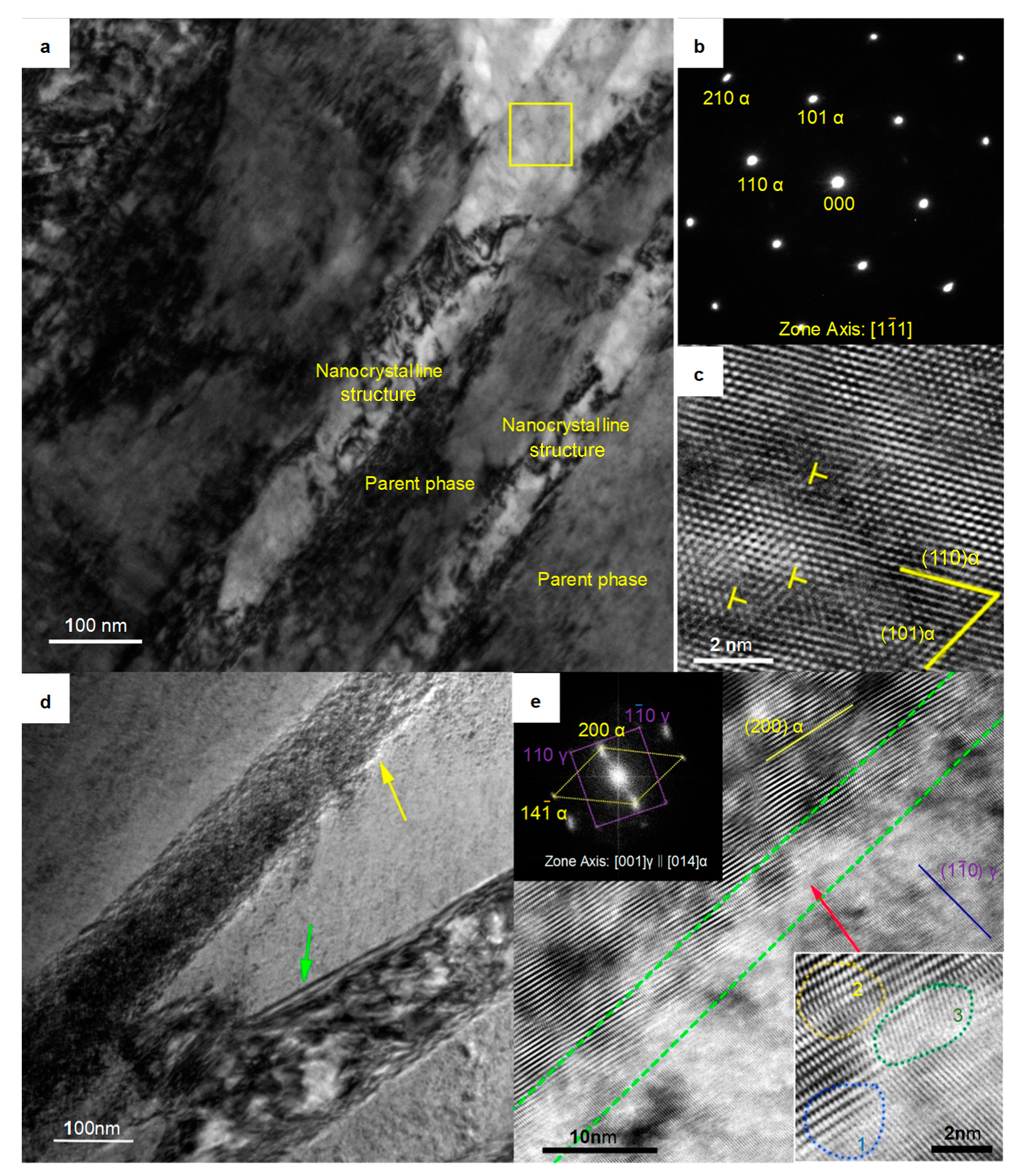
The transmission electron microscopy (TEM) results clearly revealed the widths of the strips. As shown in Figure 5a, these strips did not present any discontinuities and showed widths of approximately 80 nm. Selective electron diffraction analysis was performed on the region blocked by the yellow frame, and the result is shown in Figure 5b. Although the diffraction spots of the samples austempered at 280 °C were slightly deformed, such as the (211) α diffraction spot, the selected areas still clearly showed characteristics of α-Fe crystal lattice, a result different from those of others reports in similar systems [28]. High resolution transmission electron microscope (HRTEM) analysis of the α-Fe strips showed that there were edge dislocations in the α-Fe crystal lattice, as shown in Figure 5c, which is consistent with the observations of some nanocrystalline structures in other metals [29,30]. This nanocrystalline structure had microscale length and height and nanoscale width. The strips exhibited a plate-like structure in three-dimensional space. We named it “nanoplate”.
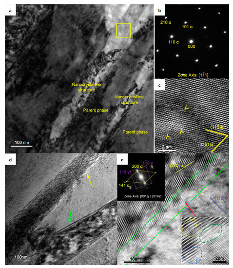
Figure 5.
TEM micrographs of the sample austempered at 280 °C. (a) Bright-field image of the parent phase and the nanocrystal phase; (b) Electron diffraction pattern of the area indicated by the yellow frame in (a). (c) High resolution transmission electron microscope (HRTEM) image of the area located in the yellow frame in (a); (d) Bright-field image of the boundary between the nanoplate and the parent phase; (e) HRTEM image of the area indicated by the yellow arrow in (d). The image at top left is the fast Fourier transform (FFT) of this image. The image at the bottom right shows an enlarged view of the area indicated by the red arrow.
The nanoplate indicated by the yellow arrow in Figure 5d was perpendicular to the viewing surface (unlike the nanoplate indicated by the green arrow in Figure 5d; there were no bands of equal thickness, which indicated a boundary that was not perpendicular to the viewing surface). There was an exceptionally bright contrast at the boundary between the nanoplate and the parent phase. Studies on the boundary structure of nanocrystalline structures have attracted great attention [31,32,33,34], so this feature was worthy of further study. HRTEM analysis was performed on this region, and, as shown in Figure 5e, the junction region between the nanoplate and the parent phase (framed by the green dashed line) had a concave–convex structure. The width of this region was approximately 5 nm. We enlarged the concave area indicated by the red arrow and found it had features characteristic of a transitional boundary: the γ-Fe lattice and the α-Fe lattice were coherent at zone 1, the α-Fe lattices were distorted in zone 2, and those in zone 3, which were adjacent to zone 2, were distinctive. The lattices in zone 3 were disordered (they did not belong to the α-Fe crystal lattice or the γ-Fe crystal lattice, while the lattices in the γ-Fe phase clearly showed a (10) γ crystal plane, and the lattices in the α-Fe phase showed a (200) α crystal plane).
The heating temperature of 950 °C, higher than 814 °C, ensured that the composition of γ-Fe crystals be homogeneous, especially in terms of the carbon content, and that the lattice structure be uniform and without defects such as dislocations. In addition, previous studies have shown that higher heating temperatures provide higher equilibrium vacancy concentrations, which contribute to the formation of nanocrystalline structure regions [35].
The boundary, which had characteristics of a transitional boundary, led to an increase in the system energy and thus showed an exceptionally bright contrast in the HRTEM image. The boundaries of the nanoplates did not have a single type of boundary structure, such as a coherent or incoherent structure boundary, as in traditional crystals. Both the lattice distortion regions (zone 2) and the disordered-state region (zone 3) of the α-Fe phase limited the widening of the α-Fe phase, ensuring the nanoscale width of the α-Fe phase. In addition, the isothermal temperature corresponded to the chemical driving force of the lattice transformation of the system. High- isothermal temperatures give the atoms a large amount of thermal motion, increasing the energy available to overcome the resistance zone and relaxing the boundary structure; therefore, it is difficult for the new phase to maintain its nanometer size. In contrast, at a lower isothermal temperature, the atoms have difficulty overcoming the resistance zone, and the new phase can maintain the nanoplate structure.
4. Conclusions
A nanocrystalline structure was formed by crystal lattice transformation in a bulk steel material. This method requires less time and energy cost than previous methods. The structural characteristics of this nanocrystalline structure were studied. The major findings and conclusions are as follows:
- (1)
- This nanocrystalline structure had microscale length and height and nanoscale width; the strips exhibited a plate-like structure in three-dimensional space. We named it “nanoplate”.
- (2)
- This nanocrystalline structure had α-Fe crystal lattice and presented edge dislocations.
- (3)
- There were unique boundaries between the nanocrystalline structures and the parent phase which consisted of three areas. These boundaries may help the nanocrystalline structure maintain a nanoscale size.
Author Contributions
Q.L. initiated this research project. T.C. and J.L. designed the experiments, prepared the initial samples, and performed the heat treatment process. T.C. performed the XRD, SEM, and TEM experiments. X.Z. and D.Z. analyzed the data and wrote the paper. All authors participated in the discussion and interpretation of the results.
Funding
This research was supported by the National Natural Science Foundation of China (No. 51601126).
Acknowledgments
We would like to thank Xiaohua Chen, Yidong Wu and Gengwu Ge (from State Key Laboratory for Advanced Metals and Materials, University of Science and Technology Beijing) for their fruitful discussion and kind help.
Conflicts of Interest
The authors declare no competing interests.
References
- Gleiter, H. Nanostructured Materials: Basic Concepts and Microstructure. Acta Mater. 2004, 35, 1–29. [Google Scholar] [CrossRef]
- Meyers, M.A.; Mishra, A.; Benson, D.J. Mechanical properties of nanocrystalline materials. Prog. Mater. Sci. 2006, 51, 427–556. [Google Scholar] [CrossRef]
- Zhao, Y.H.; Liao, X.Z.; Cheng, S.; Ma, E.; Zhu, Y.T. Simultaneously Increasing the Ductility and Strength of Nanostructured Alloys. Adv. Mater. 2006, 18, 2280–2283. [Google Scholar] [CrossRef]
- Vernieres, J.; Steinhauer, S.; Zhao, J.; Chapelle, A.; Menini, P.; Dufour, N.; Djurabekova, F.; Grammatikopoulos, P.; Sowwan, M. Gas Phase Synthesis of Multifunctional Fe-Based Nanocubes. Adv. Funct. Mater. 2017, 27, 1605328. [Google Scholar] [CrossRef]
- Xia, F.F.; Jia, W.C.; Ma, C.Y.; Yang, R.; Wang, Y.; Potts, M. Synthesis and characterization of Ni-doped TiN thin films deposited by jet electrodeposition. Appl. Surf. Sci. 2018, 434, 228–233. [Google Scholar] [CrossRef]
- Mukherjee, N.; Show, B.; Maji, S.K.; Madhu, U.; Bhar, S.K.; Mitra, B.C.; Khan, G.G.; Mondal, A. CuO nano-whiskers: Electrodeposition, Raman analysis, photoluminescence study and photocatalytic activity. Mater. Lett. 2011, 65, 3248–3250. [Google Scholar] [CrossRef]
- Wang, K.; Wu, H.; Ge, M.; Xi, W.; Luo, J. Exponential surface melting of Cu nanoparticles observed by in-situ TEM. Mater. Charact. 2018, 145, 246–249. [Google Scholar] [CrossRef]
- Mielnik-Pyszczorski, A.; Gawarecki, K.; Gawełczyk, M.; Machnikowski1, P. Dominant role of the shear strain induced admixture in spin-flip processes in self-assembled quantum dots. Phys. Rev. B 2018, 97, 245313. [Google Scholar] [CrossRef]
- Brunatova, T.; Matej, Z.; Oleynikov, P.; Vesely, J.; Danis, S.; Popelkova, D.; Kuzel, R. Thermal stability of titanate nanorods and titania nanowires formed from titanate nanotubes by heating. Mater. Charact. 2014, 98, 26–36. [Google Scholar] [CrossRef]
- Gracia Jiménez, J.M.; Cembrero, J.; Mollar, M.; Marí, B. Photoluminescent properties of electrochemically synthetized ZnO nanotubes. Mater. Charact. 2016, 119, 152–158. [Google Scholar] [CrossRef]
- Yu, B.; Leung, K.M.; Guo, Q.; Lau, W.M.; Yang, J. Synthesis of Ag–TiO2 composite nano thin film for antimicrobial application. Nanotechnology 2011, 22, 115603. [Google Scholar] [CrossRef] [PubMed]
- Chhowalla, M.; Shin, H.S.; Eda, G.; Li, L.J.; Loh, K.P.; Zhang, H. The chemistry of two-dimensional layered transition metal dichalcogenide nanosheets. Nat. Chem. 2013, 5, 263–275. [Google Scholar] [CrossRef] [PubMed]
- Tiwari, J.N.; Tiwari, R.N.; Kim, K.S. Zero-dimensional, one-dimensional, two-dimensional and three-dimensional nanostructured materials for advanced electrochemical energy devices. Prog. Mater. Sci. 2012, 57, 724–803. [Google Scholar] [CrossRef]
- Liu, X. Microstructures of Nanocrystalline Materials Synthesized by Amorphous Crystallization. Mater. Trans. JIM 1998, 39, 783–794. [Google Scholar] [CrossRef]
- Tan, X.; Xu, H.; Bai, Q.; Dong, Y. Fe-Zr-Nd-Y-B permanent magnet derived from crystallization of bulk amorphous alloy. Appl. Phys. Lett. 2007, 91, 252501. [Google Scholar] [CrossRef]
- Zhu, Y.T.; Langdon, T.G. The Fundamentals of Nanostructured Materials Processed by Severe Plastic Deformation. JOM 2004, 56, 58–63. [Google Scholar] [CrossRef]
- Dinda, G.; Rösner, H.; Wilde, G. Synthesis of bulk nanostructured Ni, Ti and Zr by repeated cold-rolling. Scr. Mater. 2005, 52, 577–582. [Google Scholar] [CrossRef]
- Sun, H.Q.; Shi, Y.N.; Zhang, M.X.; Lu, K. Plastic strain-induced grain refinement in the nanometer scale in a Mg alloy. Acta Mater. 2007, 55, 975–982. [Google Scholar] [CrossRef]
- Hilšer, O.; Rusz, S.; Szkandera, P.; Čížek, L.; Kraus, M.; Džugan, J.; Maziarz, W. Study of the Microstructure, Tensile Properties and Hardness of AZ61 Magnesium Alloy Subjected to Severe Plastic Deformation. Metals 2018, 8, 776. [Google Scholar] [CrossRef]
- Li, Y.S.; Tao, N.R.; Lu, K. Microstructural evolution and nanostructure formation in copper during dynamic plastic deformation at cryogenic temperatures. Acta Mater. 2008, 56, 230–241. [Google Scholar] [CrossRef]
- Yokota, T.; Mateo, C.G.I.; Bhadeshia, H.K.D.H. Formation of Nanostructured Steels by Phase Transformation. Scr. Mater. 2004, 51, 767–770. [Google Scholar] [CrossRef]
- Caballero, F.G.; Bhadeshia, H.K.D.H. Very Strong Bainite. Curr. Opin. Solid State Mater. Sci. 2004, 8, 251–257. [Google Scholar] [CrossRef]
- Bhadeshia, H.K. The first bulk nanostructured metal. Sci. Technol. Adv. Mater. 2013, 14, 014202. [Google Scholar] [CrossRef] [PubMed]
- Sourmail, T.; Smanio, V. Low temperature kinetics of bainite formation in high carbon steels. Acta Mater. 2013, 61, 2639–2648. [Google Scholar] [CrossRef]
- Ungár, T.; Gubicza, J.; Hanák, P.; Alexandrov, I. Densities and character of dislocations and size-distribution of subgrains in deformed metals by X-ray diffraction profile analysis. Mater. Sci. Eng. A 2001, 319–321, 274–278. [Google Scholar] [CrossRef]
- Ungár, T.; Gubicza, J.; Ribárik, G.; Borbely, A. Crystallite size distribution and dislocation structure determined by diffraction profile analysis principles and practical application to cubic and hexagonal crystals. J. Appl. Crystallogr. 2001, 34, 298–310. [Google Scholar] [CrossRef]
- Singh, K.; Kumar, A.; Singh, A. Effect of prior austenite grain size on the morphology of nano-bainitic steels. Metall. Mater. Trans. A Phys. Metall. Mater. Sci. 2018, 49A, 1348–1354. [Google Scholar] [CrossRef]
- Hulme-Smith, C.N.; Peet, M.J.; Lonardelli, I.; Dippel, A.C.; Bhadeshia, H.K.D.H. Further evidence of tetragonality in bainitic ferrite. Mater. Sci. Technol. 2015, 31, 254–256. [Google Scholar] [CrossRef]
- Edalati, K.; Horita, Z.; Valiev, R.Z. Transition from poor ductility to room-temperature superplasticity in a nanostructured aluminum alloy. Sci. Rep. 2018, 8, 8. [Google Scholar] [CrossRef]
- Hughes, D.A.; Hansen, N. Exploring the Limit of Dislocation Based Plasticity in Nanostructured Metals. Phys. Rev. Lett. 2014, 112, 5. [Google Scholar] [CrossRef]
- Chookajorn, T.; Murdoch, H.A.; Schuh, C.A. Design of stable nanocrystalline alloys. Science 2012, 337, 951–954. [Google Scholar] [CrossRef]
- Liu, X.C.; Zhang, H.W.; Lu, K. Strain-induced ultrahard and ultrastable nanolaminated structure in nickel. Science 2013, 342, 337–340. [Google Scholar] [CrossRef]
- Hu, J.; Shi, Y.N.; Sauvage, X.; Sha, G.; Lu, K. Grain boundary stability governs hardening and softening in extremely fine nanograined metals. Science 2017, 355, 1292–1296. [Google Scholar] [CrossRef]
- Zhou, X.; Li, X.Y.; Lu, K. Enhanced thermal stability of nanograined metals below a critical grain size. Science 2018, 360, 526–529. [Google Scholar] [CrossRef]
- Liu, Q.; Shen, Y.; Wu, Q.; Gao, B.; Zhang, X. Research on nucleation mechanism of the nanoscale bainite ferrite in a high carbon steel Fe–0.88C–1.35Si–1.03Cr–0.43Mn. J. Mater. Res. 2016, 31, 1510–1517. [Google Scholar] [CrossRef]
© 2018 by the authors. Licensee MDPI, Basel, Switzerland. This article is an open access article distributed under the terms and conditions of the Creative Commons Attribution (CC BY) license (http://creativecommons.org/licenses/by/4.0/).

