Article

Crack Propagation of SS304/BNi-2 Brazed Joints: Experiments and Numerical Simulations

1
College of New Energy, China University of Petroleum (East China), Qingdao 266580, China
2
Hangzhou Shenshi Energy Conservation Technology Co., Ltd., Hangzhou 311612, China
*
Author to whom correspondence should be addressed.
Metals 2019, 9(10), 1031; https://doi.org/10.3390/met9101031
Submission received: 1 August 2019 / Revised: 15 September 2019 / Accepted: 17 September 2019 / Published: 23 September 2019

Abstract

:
The strength of brazed joints is of great significance for plate-fin heat exchangers. Although a lot of research on the strength of brazed joints has been carried out, few studies have focused on the whole process of the crack propagation of brazed joints under loading, and no accurate simulation methods have been published. In this paper, the crack propagation of SS304/BNi-2 brazed joints was investigated by both experiments and numerical simulations. The cohesive zone model (CZM) was applied to simulate the crack propagation. The cohesive energy was obtained by the T-type brazed joint peeling experiments. The cohesive strength was determined as 30 MPa by comparing the load–displacement curves from the simulations and experiments. The results showed that the crack propagation process predicted by the CZM was consistent with the experimental results. Furthermore, with the increase of displacement applied on the specimen, the rate of crack propagation of the brazed joints was high at the beginning, and then gradually slowed down in the later stages. Under displacement-controlled conditions, increasing the thickness and the yield strength of the base metal could delay the crack initiation, but it would increase the crack growth rate once the crack was initiated.

1. Introduction

At present, because of its large heat transfer area and high heat transfer efficiency, plate-fin heat exchangers are widely used in aerospace, nuclear power and fuel cells, oil engineering, and other fields [1,2,3]. A plate-fin heat exchanger is composed of baffle plates, fins, and seals, which are connected by brazing. Under the influence of the temperature difference and pressure difference between the hot and cold runner medium, the brazed joint is subjected to constant erosion, and the brazed seam is easy to crack. Therefore, an investigation on the crack propagation of brazed joints in plate-fin heat exchangers is of great value in engineering applications.
The reliability of brazed joints against the propagation of pre-existing defects and cracks relies on the strength of brazed joints. Many researchers have mainly focused on the effects of the brazing process, temperature, material composition, and surface roughness on the strength of brazed joints [4,5,6,7]. In addition, the effect of residual stress on the fracture toughness of brazed joints has been studied by experiments and finite element simulation [8,9,10]. At present, the traditional fracture mechanics method is widely used in the study of crack propagation behavior. However, this method is often used for the study of macroscopic cracks, and it is not suitable for the study of crack initiation [11,12,13]. Besides, it has been commonly accepted that the single-parameter fracture criterion shows dependency on the specimen geometry and loading configurations [14]. Therefore, although many experiments and simulations on the strength of brazed joints have been carried out, few studies have focused on the whole process of the initiation and crack propagation of the brazed joints, and no accurate calculation methods have been published.
The research methods on crack propagation mainly include analytical methods and numerical simulation methods. As analytical methods have great limitations in engineering applications, it is of great significance to use numerical methods to simulate the crack propagation accurately and effectively. The numerical simulation methods can be used to observe the crack propagation process, calculate the load bearing capacity of the structures with crack defects, put forward measures to prevent crack extension, and determine the service life of the structure. With the development of computer technology and deep research, various numerical simulation methods have been developed, such as the boundary element method [15], element free method [16], extended finite element method [17], and finite element method [18]. At present, the finite element method (FEM) is the most commonly used. The grid division of the crack tip in FEM has a great influence on the simulations of the crack propagation process. There are five methods to implement the fracture mechanics concept in the finite element method, namely: the node release technique [19], embedded discontinuity model [20], remeshing techniques [21], virtual crack closure technique [22], and cohesive zone model.
The cohesive zone model (CZM) was first described in the 1960s by Dugdale [23] and Barenblatt [24]. As a two-parameter fracture analysis tool, CZM is capable of interface fracture analysis, and is independent of geometry and loading. Compared with the traditional fracture mechanics method, CZM avoids the stress singularity of the crack tip in the linear elastic fracture mechanics [25]. CZM does not require pre-cracks, so it can not only simulate crack initiation, but also simulate crack growth. Tvergaard and Hutchinson [26] applied CZM to the fracture simulation of a multi-layer bonded structure under a monotone load. Yang [27] simulated the fairly large plastic deformation of the type-II fracture of the adhesive joint using CZM. They successfully simulated the fracture process of adhesive joints with different geometric shapes with the same cohesion parameters, and proved that CZM was adapted for the fracture prediction of various joints. Moreover, CZM has achieved popularity in simulating the fracture process in laminated [28,29], fiber [30,31], and honeycomb [32] composite material structures, and so on. Ghovanlou [33] studied the crack propagation process in low-carbon steel brazed joints with copper-filled metal using CZM, and the finite element simulation results were in good agreement with the experimental data, indicating that CZM has a good applicability in the crack propagation of brazed joints. However, although CZM has a stronger advantage than the traditional fracture mechanics method for simulating crack propagation, only a few researchers adopted CZM to study the crack propagation law of brazed joints.
In this paper, the crack propagation of SS304/BNi-2 brazed joints in the plate-fin heat exchangers was investigated by both experiments and numerical simulations. CZM based on continuum damage mechanics was firstly developed to simulate the crack initiation and propagation of SS304/BNi-2 brazed joints. The validity of CZM was proven by comparing the simulated results with the T-type brazed joint peeling experimental results. Then, the whole process of crack propagation and the propagation law of the brazed joint were obtained. Furthermore, the influence of the thickness and the yield strength of the base metal on the crack propagation of brazed joints was investigated and discussed.

2. Materials and Experiments

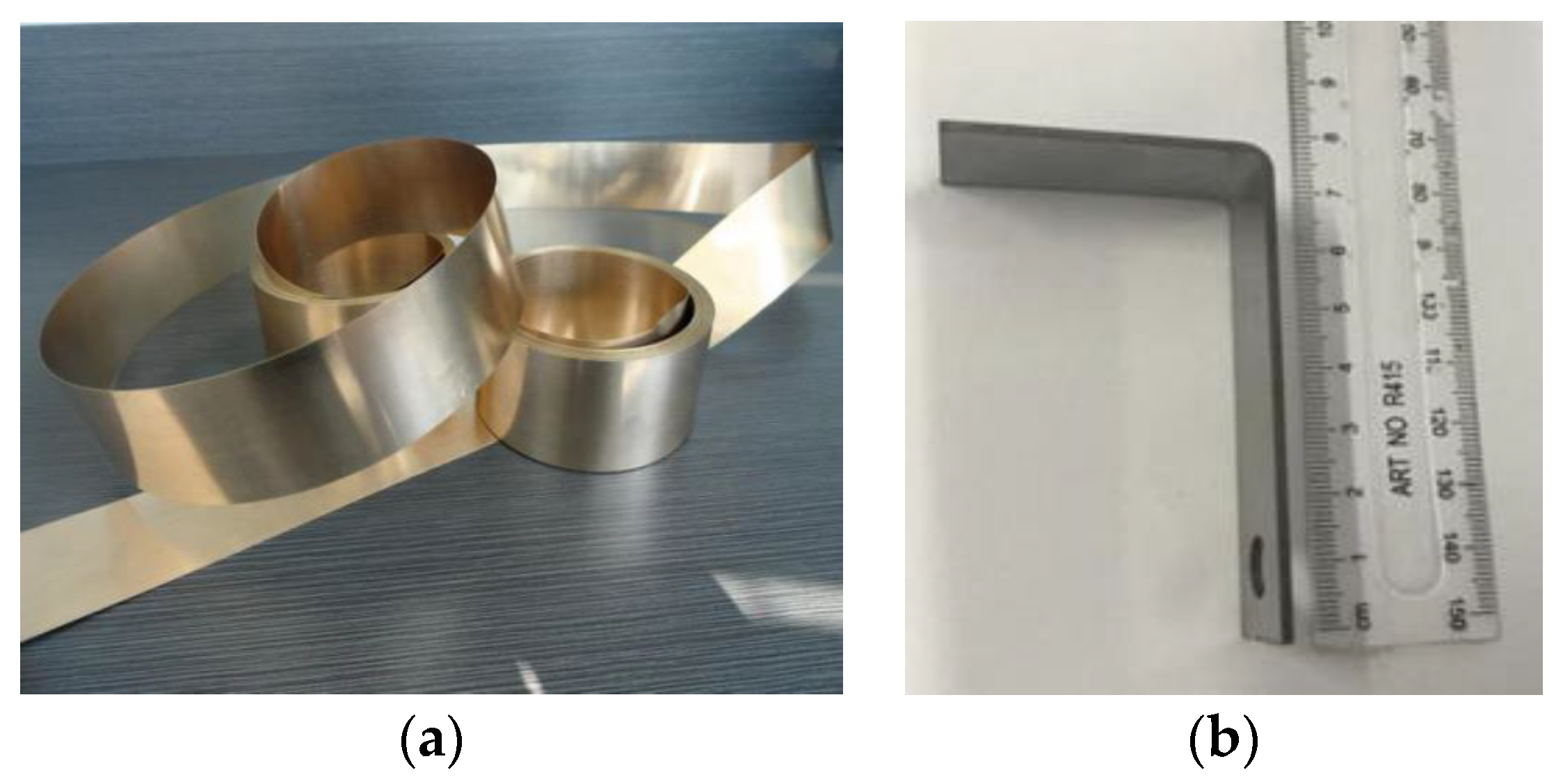
2.1. T-Type Brazed Joint Peeling Experiments

In this paper, the materials for the base metal and filler metal were SS304 steel and nickel-based filler metal BNi-2, respectively. Their chemical compositions are listed in Table 1, where the symbol “-” means the chemical element is not contained in this material.
At present, there are no relevant standards on the crack propagation experiment of the brazed joint of plate-fin heat exchangers. Considering that the stress state and crack propagation behavior of the plate-fin brazed joints are similar to the adhesive structure of T-type joints, we used an adhesive T-type brazed joint to study the crack propagation laws of a plate-fin brazed joint. According to the Standard of the GB/T 2791-1995 adhesive T peeling strength test method, we designed a T-type brazed joint, as shown in Figure 1a.
According to the brazing process designed by Jiang [34], two L-type stainless steel plates (SS304 material) were brazed together by the BNi-2 filler metal, as shown in Figure 1b. The width of the stainless-steel plate was 20 mm, and the thickness was 1 mm. The brazing seam was located at the center section of the specimen. The thickness of the BNi-2 filler metal foil was 40 μm, as shown in Figure 2a. Therefore, two layers of BNi-2 foil were applied to the welded part of the L-type 304 stainless steel (Figure 2b) in order to obtain an 80 μm thickness of the filler metal. The length of the holding end was 70 mm, the brazing part was 40 mm in length, and the brazing part and the holding end passed through a fillet of 2 mm. The notch diameter was 8 mm.
In this paper, the tensile crack propagation experiment of the brazed joints was carried out at room temperature using a creep testing machine; the test device and sample holding are shown in Figure 3a,b, respectively. The experiments were conducted under a displacement-controlled condition at a rate of 0.005 mm·s−1. The load and displacement were recorded during the tensile test.

2.2. Experimental Results

Three experiments were carried out under the same conditions, and the load–displacement curves that were obtained are shown in Figure 4. It can be seen that there are some differences in the three curves, which is mainly due to the differences in the welding quality. However, the difference of the stable load, which is used to calculate the cohesive energy, is small. The values of the maximum load and stability load that were obtained by each specimen are listed in Table 2. The average values will be used in the determination of the critical cohesive energy.

3. Finite Element Analysis

3.1. Cohesive Zone Modeling

The cohesive zone model defines a traction–separation relationship in order to account for the progressive damage and fracture mechanisms along a fracture surface. Various cohesive models, such as the bilinear [35], trapezoid [36], exponential [37], and monotonically decreasing [38] models, have been developed in order to simulate the fracture of different materials. In the standard finite element method, the cohesive zone model is generally implemented by introducing cohesive contact surfaces. Prior to the computational simulation, cohesive contact surfaces were inserted between the continuum elements within a potential crack path, which led to an intrinsic cohesive zone modeling approach.
In this work, for the traction–separation relationship of the cohesive zone model, a bilinear cohesive model was employed, as shown in Figure 5. According to the fracture process of the material, the model can be divided into the following three phases: the elastic deformation stage (line OA), the damage evolvement stage (line AC), and the complete failure stage (line CD). In the elastic deformation stage, the slope was the penalty stiffness (k), which could defend the cohesive element surfaces from the separation. In other words, the displacement compatibility between the FEs was ensured approximately in the elastic stage via a penalty function method. When the effective separation (δm) was bigger than the effective separation at the damage initiation ( δ m 0 ), the corresponding cohesive element entered the damage evolvement stage. In this stage, the material began to damage.
Once the effective separation, δm, reached the effective separation at complete failure, δ m f , the two surfaces of the cohesive element separated from each other completely, and a new surface crack was formed. The closure of the cracks could be simulated via contact methods in order to deal with the interaction between the crack surfaces.
From the analysis above, we can find that the cohesive model mainly includes three important parameters (δm, δ m 0 , and δ m f ), which can be utilized to determine the stage of a cohesive element.
The effective separation (δm) is defined as follows:
δ m = δ 1 2 + δ 2 2 + δ 3 2
where δ1 is the normal separation component, while δ2 and δ3 are the tangential separation components. The Macaulay bracket (<·>) can be represented as follows:
If   δ 1   >   0 ,   δ 1 = δ 1 ;   else   δ 1 = 0
The maximum nominal stress criterion is employed to determine whether the material begins to damage. This criterion can be represented as follows:
max = { t 1 t 1 0 , t 2 t 2 0 , t 3 t 3 0 } = 1
where t1 is the normal traction component, while t2 and t3 are the tangential traction components. t 1 0 is the tensile strength in mode I, while t 2 0 and t 3 0 are the shear strengths in modes II and III, respectively.
The same penalty stiffness was utilized for modes I, II, and III, and the tractions in the elastic stage were as follows:
t i = k δ i ,   ( I =   1 ,   2 ,   3 )
t i 0 = k δ i 0 ,   ( I =   1 ,   2 ,   3 )
where δ 1 0 is the separation component at the initial damage for mode I, while δ 2 0 and δ 3 0 are those for modes II and III, respectively.
When a cohesive element enters the damage evolvement stage, its stiffness monotonously decreases. The stiffness degradation coefficient (D) is defined as follows:
D = δ m f ( δ m max δ m 0 ) δ m max ( δ m f δ m 0 )
where δ m 0 = σmax,0/k and δ m f = 2Gcmax,0. The cohesive strength (σmax,0) is the maximum traction attained with the fracture process zone at the onset of the damage initiation, and the cohesive energy (Gc) is the work needed for the full material separation per unit area of the crack extension. The maximum value of the effective separation during the loading history ( δ m m ax ), is defined as follows:
δ m max = max { δ m max , δ m }
In the damage evolvement stage, the normal and tangential tractions were as follows:
t i = ( 1 D ) k δ i ,   ( I =   1 ,   2 ,   3 )

3.2. Finite Element Model

In this work, the crack propagation process of the T-type brazed joints was modeled using the commercial finite element software ABAQUS. The geometric dimensions of the model were the same as the size of the sample in the experiments, as shown in Figure 1a. A two-dimensional finite element model was built. The initial constitutive thickness of the cohesive elements was set equal to the joint clearance of 80 μm.
The critical cohesive energy, initial stiffness, and the cohesive strength of the brazed joint will be studied in the next section. The hardening behavior of the base metal was taken from the tensile tests, and the corresponding stress values versus the plastic strains are provided in Table 3.
In the simulation, a general static analysis step was applied, and a geometric nonlinear analysis was adopted. The FE model of the T-type specimen and its boundary conditions are shown in Figure 6. In order to make the simulation closer to the experimental value, it is necessary to set the boundary conditions to be the same as the test conditions. Considering the limiting effect of the clamp on the specimen during the experiments, the upper and lower ends of the specimen model were divided into regions with the same length as the clamp. The lateral displacements of the regions in the X direction were limited. The lower end of the T-type specimen was fixed. An upward displacement with a loading rate of 0.005 mm·s−1 was applied on the end face of the upper end.

3.3. Mesh Convergence Study

Studies show that it is more reasonable to use one base metal element to correspond to 2~5 cohesive elements [39,40]. Therefore, one base metal element corresponding to four cohesive elements will be used in this work. In the simulation, the two-dimensional cohesive element type was COH2D4, with four nodes and two integration points. The brazed joint interlayer was divided into a single row of cohesive elements along the thickness direction. The surrounding base metal regions were meshed by a four-node bilinear plane strain quadrilateral, reduced integration, hourglass control element, and CPE4R. The finite element meshing of the T-type brazed joint is shown in Figure 7.
A mesh convergence study was carried out in order to obtain the suitable size of the cohesive element (LCZM). Four different sets of finite element meshes were divided, and the sizes of the base metal element were 0.4, 0.2, 0.1, and 0.04 mm, and the corresponding sizes of the cohesive elements were 0.1, 0.05, 0.025, and 0.01 mm, respectively. The load–displacement curves obtained with different cohesive element sizes are shown in Figure 8. It can be seen that before the load reached the maximum, the resulting curves of the different cohesive element sizes almost overlapped. However, the maximum loads diverged. The detail results are shown in Table 4. It is shown that when the mesh size reached 0.025 mm, the maximum loads were convergent and almost unaffected by the mesh sizes. Therefore, 0.025 mm can be regarded as the critical mesh size of the cohesive elements, and was determined as the cohesive element size in this work. Accordingly, the size of the base metal elements is 0.1 mm. Finally, the FE model consisted of 23,180 elements and 26,890 nodes, as shown in Figure 7.

3.4. Determination of Critical Cohesive Energy and Cohesive Strength

The peeling test was a popular test method for measuring the peeling energy between flexible laminates [41,42]. For the brazed joint, the total input energy (G) in the test was related to the stable peeling load (P), the width (b) of the specimen, and the peeling angle (θ), which are shown in the following formula:
G = P b ( 1 cos θ )
The sample was brazed by two L-type peeling arms of 304 stainless-steel, each with a peeling angle of θ = π/2, so the formula (8) can be simplified as follows:
G = P b
The total input energy (G) includes the critical cohesive energy (Gc) and the plastic dissipation energy (Gd) consumed in the bending of the peeling arm. The critical cohesive energy (Gc) is a “characteristic” property of the material, independent of the thickness (h) of the peeling arm and the peeling angle (θ). However, the value of Gc may be affected by the loading rate and temperature.
Georgiou [43] and Kawashita [44] deduced the calculation method of plastic dissipation energy (Gd) from the theory, and obtained the formula of the critical cohesive energy (Gc), given by the following:
G c = θ 0 2 G 2 σ y h + σ y 2 2 E
where E is the elastic modulus, σy is the yield strength of the peeling arm, and θ0 is the root rotation.
The value of θ0 is determined by the characteristic length of the deformation (Δ), as shown in Figure 9, and is defined by the following:
θ 0 = Δ h
The value Δ/h is related to the geometrical and elastic modulus of the specimen, as shown in Formula (12), where Ec is the elastic modulus of the solder, hc is the filler metal thickness. It should be noted that Formula (12) is actually obtained under the assumption of a linear stiffness curve [43]. So, the function of this formula is just to give an estimate value of Gc in this work.
( Δ h ) 4 = 1 6 E E c ( 1 + 2 h c h E E c )
The cohesive energy obtained from the experiment was assigned to the cohesive elements. The cohesive zone stiffness, which is equal to the slope of the linear elastic part of the traction–separation law, is defined by the following [45]:
k = E c h c
The values of the material parameters, geometrical dimensions of the base material, the brazing filler metal, and the critical cohesive energy obtained by the calculations are listed in Table 5.
Another important parameter in the simulation was the cohesive strength. The method used in this paper was to simulate the crack propagation of the brazed joint by assuming different values of cohesive strength, and comparing the simulated load–displacement curves with the experimental curves, then seeking the optimum value. Figure 10 shows the load–displacement curves obtained with different cohesive strength values. It can be seen that the final loads increased with the cohesive strength values. Table 6 shows the comparison of the maximum load and final load by the experiments and simulations with different cohesive strength values. The errors between the experimental and simulated results were at a minimum when the cohesive strength was 30 MPa. The error between the maximum load and the test value was 0.08%, and the error between the final load and the test value was 1.32%. Therefore, the value of the cohesive strength in this paper was determined as 30 MPa.

4. Results and Discussion

4.1. Crack Propagation Law Analysis

The crack growth results obtained by the simulations and experiments are shown in Figure 11. The experimental results showed that the crack grew through the joint filler metal region, and no delamination occurred at the steel interface. It has been proven that it is correct to set the cohesive element in the brazing seam. The deformation of the base metal and the crack length of the brazed joint obtained by the simulations were close to the experimental results, which further showed that the bilinear cohesive zone model can predict the crack propagation of the brazed joint accurately. Furthermore, with the loading of the displacement, there was plastic deformation of the base metal, which consumed a lot of energy. This could explain why the cohesive energy of Gc = 10.45 mJ·mm−2 was less than the total energy of G = 40.29 mJ·mm−2.
The damage of the first element at the edge of the brazing seam is plotted in Figure 12. It can be seen that before displacement reached Point A, the damage was zero. With the increase of displacement, the rate of the damage growth was high at first and then slowed down. When the displacement reached Point B, the damage reached one. The crack initiation time was defined as the calculated time needed for the damage to change from zero to Point B in the simulation. Figure 13 shows the traction distribution along the edge of the brazing seam at different damage stages of crack initiation. The first cohesive element located at the initial crack tip had the largest traction, and the traction decreased gradually to zero along the weld seam, as shown in Curve 1. When the traction reached a cohesive strength of 30 MPa (Point A in Figure 12), the damage initiated and increased nonlinearly. A further increase in the separation resulted in the gradual degradation of the damage-initiated cohesive elements along the interlayer. Accordingly, the traction dropped below the cohesive strength of 30 MPa (Curve 2). When the loading displacement reached 0.85 mm, the damage accumulated to one (Point B in Figure 12), and the traction reached zero for the first fully damaged cohesive element (Curve 3). The cohesive element was deleted to simulate the crack initiation when its damage accumulated to one and its traction reached zero in the simulation.
The stress distributions of the brazing joint with different crack lengths are shown in Figure 14a–d. Correspondingly, the damage and traction distribution of the cohesive elements along the brazing seam are shown in Figure 15a,b and Figure 16. As the figures show, the seam can be divided into three stages, namely: crack section, damage accumulation section, and undamaged section. In the cracked section, the cohesion unit damage reached one, and the corresponding traction was reduced to zero, which lad to the disappearance of the cohesion element, and the crack extended to the deeper position of the brazing seam. It can be seen from the damage magnification diagram that the damage near the tip of the crack reached more than 0.999, which caused this part to experience failure under a little separation.
Figure 17 shows the simulated crack length curve in comparison with the experimental results. The experimental crack lengths were measured by the direct current (DC) method. The simulated crack lengths were calculated by multiplying the element length by the number of the deleted elements. It can be seen that the trend of the simulated curve is similar to that obtained by the experiment, which shows that it is feasible to simulate the crack propagation of the brazed joint by CZM. However, the value of the crack length measured by the experiment was slightly larger than that of the simulation. This is because the brazed joint in the experiment had some defects during the brazing process, which were not considered in the simulation. Furthermore, the difference in the crack length definition between the experiments and simulation could be another reason.

4.2. Effect of Thickness of Base Metal on Crack Propagation

In order to study the effect of the thickness of the base metal on the crack propagation of the brazed joint, the thickness of the 304 stainless steel was set to 1, 2, 3, and 4 mm, respectively. The other parameters (E and σy) remained the same, as listed in Table 5. The thickness of the filler metal remained 80 μm. The displacement applied on the end of the brazed joint was also 6 mm. The effects of the base metal thickness on the load–displacement curve and crack initial time are shown in Figure 18a,b. It shows that the load that the brazed joint can bear increased, and the crack initiation time of brazed joint became longer with the increase of the base metal thickness. Therefore, increasing the thickness of the base metal can slow down the crack initiation of the brazed joint.
Figure 19a shows the effect of the base metal thickness on the crack length. The crack growth rate of the brazed joint increased with the increase of the base metal thickness. With the displacement increasing, the length of the crack became longer. This is because with the increase of the base metal thickness of the T specimens, the cross section of the stripping arm increased, resulting in an increase in the stiffness of the material and a decrease of the elastic deformation. When the same displacement was applied, the joint was easier to tear in a larger area. Therefore, although increasing the thickness of the base metal can slow down the crack initiation of the brazed joint, the crack growth rate of the brazed joint will increase with the base metal thickness, once the crack is formed. The relation between the crack length and the base metal thickness when the displacement load was 6 mm was obtained by fitting the points in Figure 19b. It can be seen that the crack growth length had a linear relationship with the base metal thickness.

4.3. Effect of Yield Strength of Base Metal on Crack Propagation

It is well known that the yield strength of the same steel material varies greatly with different heat treatment methods. To study the effect of the heat treatment on the crack resistance of brazing joints, simulations of the cracking propagation of brazed joints with different yield strengths were conducted. An elastoplastic constitutive model was adopted for the base metal, but the hardening behavior was not considered. The thickness of the base metal was set to 1 mm. The other parameters remained the same as listed in Table 5. The thickness of the filler metal remained at 80 μm. The effect of the yield strength on the load–displacement and crack initial time of the brazed joint was obtained, as shown in Figure 20a,b. It can be seen that with the increase of the yield strength of the base metal, the maximum load and the steady load that the brazed joint can bear increased. Increasing the yield strength of the base metal can improve the ability of the brazed joint to resist cracking. This is because the total energy required for the peeling test increased with the increase of the steady load, and the energy consumed by the plastic deformation of the base metal increased when the critical cohesive energy was constant, and the time required for the initiation of brazed joints increased.
Figure 21a shows the effect of the yield strength on the crack length. It is shown that with the loading of the displacement, the crack growth rate of the brazed joint increased with the yield strength. This is because the greater the yield strength of the metal material, the stronger the ability to resist plastic deformation, and the smaller the flexibility. When applying the same displacement load, a longer crack length was easily formed on the brazed joint of a greater yield strength. When the 6 mm displacement load was applied, the relationship between the crack length and the yield strength of the base metal was obtained by fitting the points in Figure 21b. The crack growth length was linear with the yield strength of the base metal.
Based on the above analysis, it can be seen that under controlled displacement conditions, increasing the thickness of the base metal not only slowed down the crack initiation of the brazed joint, but also increased the crack growth rate of the brazed joint once the crack was formed. When the thickness of the base metal was a fixed value, increasing the yield strength of the base metal could improve the ability of the brazed joint to resist cracking, but the crack growth rate of the brazed joint would also increase in the meanwhile. Therefore, to resist the crack propagation of brazed joints in engineering applications, a suitable thickness and the necessary heat treatment of the base metal need to be determined by measuring both the crack initiation and the crack growth rate.

5. Conclusions

In this paper, the bilinear cohesive zone model (CZM), as a two-parameter fracture analysis tool, has been successfully applied to predict the whole process of the crack propagation of SS304/BNi-2 brazed joints. The following conclusions are drawn from this study:
(1) The crack propagation experiments of SS304/BNi-2 brazed joint were carried out. The energy consumed by the plastic deformation of the base metal is eliminated from the total energy input from the crack propagation by the analytic method. As one of the CZM parameters, the critical cohesive energy of the brazed joints calculated by the experimental data is 10.45 mJ·mm−2.
(2) The cohesive strength, another important parameter in CZM, is determined by comparing the simulated results with the experimental results. The crack propagation of the brazed joint with different values of cohesive strength is simulated using CZM. The load–displacement curves obtained by simulation were compared with the experimental curves. The cohesive strength with the minimum error between the simulation and experiment is the optimum value. Finally, the value of the cohesive strength is determined as 30 MPa.
(3) The predicted results of the crack propagation of the T-type brazed joints are in good agreement with the experimental results. The agreement shows that CZM can predict the crack propagation of the brazed joint accurately. The results show that with the increase of the displacement loading, the rate of crack propagation is high at the beginning, and then gradually slows down in the later stage.
(4) The influence of the thickness and the yield strength of the base metal on the crack propagation of brazed joints was investigated. The results show that under the controlled displacement condition, increasing the yield strength or the thickness of the base metal can delay the crack initiation of the brazed joint, but that it will increase the crack growth rate of the brazed joint once the crack is formed.

Author Contributions

Conceptualization, F.Z. and W.J.; investigation, J.T.; software, F.Z.; writing (original draft), J.T.; writing (review and editing), F.Z. and W.J.; methodology, J.S. and D.Y.; resources, J.S. and D.Y.

Funding

The authors gratefully acknowledge the support provided by the National Natural Science Foundation of China (no. 11372359), the Natural Science Foundation for Distinguished Young Scholars of Shandong Province (no. JQ201417), the Fundamental Research Funds for the Central Universities (no. 15CX08006A and no. 18CX02147A), and the Natural Science Foundation of Shandong Province (no. ZR2019BEE061).

Conflicts of Interest

The authors declare no conflict of interest.

Nomenclature

acrack length t 2 0 : t 3 0 shear strengths in modes II and III
bwidth of the specimenxloading displacement
Dstiffness degradation coefficientδ1normal separation component
Eelastic modulusδ2, δ3tangential separation components
Ecelastic modulus of the solder δ 1 0 separation component at initial damage for mode I
Gtotal input energy δ 2 0 , δ 3 0 separation component at initial damage for modes II and III
Gccritical cohesive energyδmeffective separation
Gdplastic dissipation energy δ m 0 damage initiation
hthickness of the peeling arm δ m f effective separation at complete failure
hcfiller metal thickness δ m max the maximum value of the effective separation
kslope of the linear elastic part of the traction-separation lawδi(i = 1,2,3) separation components
LCZMsize of the cohesive elementΔcharacteristic length of the deformation
Pstable peeling loadθpeeling angle
t1normal traction componentθ0root rotation
t2, t3tangential traction componentsσyyield strength of the peeling arm
t 1 0 tensile strength in mode I

References

  1. Chang, H.-M.; Gwak, K.H. New application of plate–fin heat exchanger with regenerative cryocoolers. Cryogenic 2015, 70, 1–8. [Google Scholar] [CrossRef]
  2. Sundén, B.; Fu, J. Chapter 6—Aerospace Heat Exchangers. In Heat Transfer in Aerospace Applications; Academic Press: New York, NY, USA, 2017; pp. 89–115. [Google Scholar]
  3. Bartel, N.; Chen, M.; Utgikar, V.; Sun, X.; Kim, I.-H.; Christensen, R.; Sabharwall, P. Comparative analysis of compact heat exchangers for application as the intermediate heat exchanger for advanced nuclear reactors. Ann. Nucl. Energy 2015, 81, 143–149. [Google Scholar] [CrossRef] [Green Version]
  4. Jiang, W.; Gong, J.; Tu, S. A study of the effect of filler metal thickness on tensile strength for a stainless steel plate-fin structure by experiment and finite element method. Mater. Des. 2010, 31, 2387–2396. [Google Scholar] [CrossRef]
  5. Feng, J.; Liu, D.; Zhang, L.; Lin, X.; He, P. Effects of processing parameters on microstructure and mechanical behavior of SiO2/Ti–6Al–4V joint brazed with AgCu/Ni interlayer. Mater. Sci. Eng. A 2010, 527, 1522–1528. [Google Scholar] [CrossRef]
  6. Jiang, W.; Gong, J.; Tu, S. Effect of holding time on vacuum brazing for a stainless steel plate–fin structure. Mater. Des. 2010, 31, 2157–2162. [Google Scholar] [CrossRef]
  7. Nishi, H.; Kikuchi, K. Influence of brazing conditions on the strength of brazed joints of alumina dispersion-strengthened copper to 316 stainless steel. J. Nucl. Mater. 1998, 258, 281–288. [Google Scholar] [CrossRef]
  8. Fu, L.D.; Miyashita, Y.; Mutoh, Y. Elastoplastic Singular Behavior of Residual Stress in Si3N4/S45C Joint with Copper Interlayer. Key Eng. Mater. 2004, 274, 1011–1016. [Google Scholar] [CrossRef]
  9. Xu, S.; Wang, S.; Zhao, Y.; Jiang, W. The residual stress in a brazed joint of metallic bipolar plates of PEMFC: A numerical model. Int. J. Hydrog. Energy 2016, 41, 5304–5314. [Google Scholar] [CrossRef]
  10. Jiang, W.; Liu, Z.; Gong, J.; Tu, S. Numerical simulation to study the effect of repair width on residual stresses of a stainless steel clad plate. Int. J. Press. Vessel. Pip. 2010, 87, 457–463. [Google Scholar] [CrossRef]
  11. Cornetti, P.; Sapora, A.; Carpinteri, A. Short cracks and V-notches: Finite Fracture Mechanics vs. Cohesive Crack Model. Eng. Fract. Mech. 2016, 168. [Google Scholar] [CrossRef]
  12. Taylor, D.; Cornetti, P.; Pugno, N. The fracture mechanics of finite crack extension. Eng. Fract. Mech. 2005, 72, 1021–1038. [Google Scholar] [CrossRef]
  13. Henninger, C.; Leguillon, D.; Martin, E. Crack initiation at a V-notch—Comparison between a brittle fracture criterion and the Dugdale cohesive model. C. R. Méc. 2007, 335, 388–393. [Google Scholar] [CrossRef]
  14. Ghovanlou, M.K.; Jahed, H.; Khajepour, A. Mechanical reliability characterization of low carbon steel brazed joints with copper filler metal. Mat. Sci. Eng. A Struct. 2011, 528, 6146–6156. [Google Scholar]
  15. Tan, C.L. Boundary element methods in creep and fracture. Can. J. Civ. Eng. 1983, 10, 780–781. [Google Scholar] [CrossRef]
  16. Dong, Y.; Wu, S.; Xu, S.; Zhang, Y.; Fang, S. Fracture of concrete structure using simplified meshless method. Cem. Concr. Res. 2009, 39, 966–972. [Google Scholar] [CrossRef]
  17. Dolbow, J.; Belytschko, T.; Moës, N. A finite element method for crack growth without remeshing. Int. J. Numer. Methods Eng. 1999, 46, 131–150. [Google Scholar]
  18. Yang, J.; Wang, L. Optimizing the Local Strength Mismatch of a Dissimilar Metal Welded Joint in a Nuclear Power Plant. Metals 2018, 8, 494. [Google Scholar] [CrossRef]
  19. Bouchard, P.; Bay, F.; Chastel, Y. Numerical modelling of crack propagation: Automatic remeshing and comparison of different criteria. Comput. Methods Appl. Mech. Eng. 2003, 192, 3887–3908. [Google Scholar] [CrossRef]
  20. Wells, G.; Sluys, L.; Wells, G. Three-dimensional embedded discontinuity model for brittle fracture. Int. J. Solids Struct. 2001, 38, 897–913. [Google Scholar] [CrossRef]
  21. Maligno, A.; Rajaratnam, S.; Leen, S.; Williams, E. A three-dimensional (3D) numerical study of fatigue crack growth using remeshing techniques. Eng. Fract. Mech. 2010, 77, 94–111. [Google Scholar] [CrossRef]
  22. Krueger, R. Virtual crack closure technique: History, approach, and applications. Appl. Mech. Rev. 2004, 57, 109–143. [Google Scholar] [CrossRef]
  23. Dugdale, D. Yielding of steel sheets containing slits. J. Mech. Phys. Solids 1960, 8, 100–104. [Google Scholar] [CrossRef]
  24. Barenblatt, G. The Mathematical Theory of Equilibrium Cracks in Brittle Fracture. Adv. Appl. Mech. 1962, 7, 55–129. [Google Scholar]
  25. Pirondi, A.; Moroni, F. Improvement of a Cohesive Zone Model for Fatigue Delamination Rate Simulation. Materials 2019, 12, 181. [Google Scholar] [CrossRef]
  26. Tvergaard, V.; Hutchinson, J.W. Toughness of an interface along a thin ductile layer joining elastic solids. Philos. Mag. A 1994, 70, 641–656. [Google Scholar] [CrossRef]
  27. Yang, Q.; Thouless, M.; Ward, S. Elastic–plastic mode-II fracture of adhesive joints. Int. J. Solids Struct. 2001, 38, 3251–3262. [Google Scholar] [CrossRef]
  28. Zou, Z.; Reid, S.; Li, S. A continuum damage model for delaminations in laminated composites. J. Mech. Phys. Solids 2003, 51, 333–356. [Google Scholar] [CrossRef]
  29. Yang, Q.; Cox, B. Cohesive models for damage evolution in laminated composites. Int. J. Fract. 2005, 133, 107–137. [Google Scholar] [CrossRef]
  30. Fan, C.; Ben Jar, P.-Y.; Cheng, J.R. Cohesive zone with continuum damage properties for simulation of delamination development in fibre composites and failure of adhesive joints. Eng. Fract. Mech. 2008, 75, 3866–3880. [Google Scholar] [CrossRef]
  31. Xie, D.; Salvi, A.G.; Sun, C.; Waas, A.M.; Caliskan, A. Discrete Cohesive Zone Model to Simulate Static Fracture in 2D Triaxially Braided Carbon Fiber Composites. J. Compos. Mater. 2006, 40, 2025–2046. [Google Scholar] [CrossRef]
  32. Han, T.-S.; Ural, A.; Chen, C.-S.; Zehnder, A.T.; Ingraffea, A.R.; Billington, S.L. Delamination buckling and propagation analysis of honeycomb panels using a cohesive element approach. Int. J. Fract. 2002, 115, 101–123. [Google Scholar] [CrossRef]
  33. Ghovanlou, M.K.; Jahed, H.; Khajepour, A. Cohesive zone modeling of ductile tearing process in brazed joints. Eng. Fract. Mech. 2013, 102, 156–170. [Google Scholar] [CrossRef]
  34. Jiang, W.; Gong, J.; Tu, S.T. Effect of brazing temperature on tensile strength and microstructure for a stainless steel plate-fin structure. Mater. Des. 2010, 32, 736–742. [Google Scholar] [CrossRef]
  35. Mi, Y.; Crisfield, M.A.; Davies, G.A.O.; Hellweg, H.B. Progressive Delamination Using Interface Elements. J. Compos. Mater. 1998, 32, 1246–1272. [Google Scholar] [CrossRef]
  36. Tvergaard, V.; Hutchinson, J.W. The relation between crack growth resistance and fracture process parameters in elastic-plastic solids. J. Mech. Phys. Solids 1992, 40, 1377–1397. [Google Scholar] [CrossRef]
  37. Barenblatt, G.I. The formation of equilibrium cracks during brittle fracture. General ideas and hypotheses. Axially-symmetric cracks. J. Appl. Math. Mech. 1959, 23, 622–636. [Google Scholar]
  38. Camacho, G.; Ortiz, M. Computational modelling of impact damage in brittle materials. Int. J. Solids Struct. 1996, 33, 2899–2938. [Google Scholar] [CrossRef]
  39. Turon, A.; Dávila, C.G.; Camanho, P.P.; Costa, J. An engineering solution for mesh size effects in the simulation of delamination using cohesive zone models. Eng. Fract. Mech. 2007, 74, 1665–1682. [Google Scholar] [CrossRef]
  40. Zhou, F.; Molinari, J.-F.; Shioya, T. A rate-dependent cohesive model for simulating dynamic crack propagation in brittle materials. Eng. Fract. Mech. 2005, 72, 1383–1410. [Google Scholar] [CrossRef]
  41. Kinloch, A.J.; Lau, C.C.; Williams, J.G.; Kinloch, A. The peeling of flexible laminates. Int. J. Fract. 1994, 66, 45–70. [Google Scholar] [CrossRef]
  42. Kim, K.-S.; Aravas, N. Elastoplastic analysis of the peel test. Int. J. Solids Struct. 1988, 24, 417–435. [Google Scholar] [CrossRef]
  43. Georgiou, I.; Hadavinia, H.; Ivankovic, A.; Kinloch, A.J.; Tropsa, V.; Williams, J.G.; Kinloch, A. Cohesive zone models and the plastically deforming peel test. J. Adhes. 2003, 79, 239–265. [Google Scholar] [CrossRef] [Green Version]
  44. Kawashita, L.F.; Moore, D.R.; Williams, J.G. The development of a mandrel peel test for the measurement of adhesive fracture toughness of epoxy–metal laminates. J. Adhes. 2004, 80, 147–167. [Google Scholar] [CrossRef]
  45. ABAQUS/CAE, Version 6.7-1; Dassault Systems: Villakublai, France, 2007.
Figure 1. Specimen for a T-type brazed joint: (a) schematic geometry and (b) photograph.
Metals 09 01031 g001
Figure 2. Brazing joint parts: (a) BNi-2 foil and (b) L-type 304 stainless steel.
Metals 09 01031 g002
Figure 3. (a) Testing machine and (b) the clamping of the T-type brazed joint.
Metals 09 01031 g003
Figure 4. The load–displacement curves.
Metals 09 01031 g004
Figure 5. The load–displacement curves.
Metals 09 01031 g005
Figure 6. Finite element (FE) model of the specimen and boundary conditions.
Metals 09 01031 g006
Figure 7. Finite element meshing of the brazed T-type specimen.
Metals 09 01031 g007
Figure 8. Load–displacement curve for different cohesive element mesh sizes.
Metals 09 01031 g008
Figure 9. Schematic diagram of θ0.
Metals 09 01031 g009
Figure 10. Load–displacement curves with different cohesive strength values.
Metals 09 01031 g010
Figure 11. Comparison of the crack propagation results: simulation vs. experiment.
Metals 09 01031 g011
Figure 12. Damage of the first element at the edge of the brazing seam.
Metals 09 01031 g012
Figure 13. Traction distribution along the edge of the brazing seam at different damage stages of crack initiation.
Metals 09 01031 g013
Figure 14. Stress distribution of the brazed joint with different crack lengths: (a) a = 0 mm, (b) a = 1 mm, (c) a = 3 mm, and (d) a = 5 mm.
Metals 09 01031 g014
Figure 15. (a) Damage distribution of the cohesive element along the weld seam after crack propagation; (b) partial enlargement.
Metals 09 01031 g015
Figure 16. Traction force of the cohesive element along the brazing seam after crack growth.
Metals 09 01031 g016
Figure 17. Simulated crack length curve compared to the experimental results.
Metals 09 01031 g017
Figure 18. (a) Effect of base metal thickness on the load–displacement curve; (b) effect of base metal thickness on the crack initial time.
Metals 09 01031 g018
Figure 19. (a) Effect of base metal thickness on crack length; (b) Fitting relationship between crack length and base metal thickness.
Metals 09 01031 g019
Figure 20. (a) Effect of yield strength on the load–displacement curve; (b) effect of yield strength on the crack initial time.
Metals 09 01031 g020
Figure 21. (a) Effect of yield strength on crack length; (b) fitting relationship between crack length and yield strength.
Metals 09 01031 g021
Table 1. Chemical composition of SS304 and BNi-2 (in wt %).
MaterialCSiMnSPCrBNiFe
304≤0.03≤1.00≤2.00≤0.03≤0.03517.0~19.0-8.00~11.0Balance
BNi-20.064.50---7.003.182.343.0
Table 2. Maximum load and stable load for each specimen.
Specimen IDMaximum Load (N)Stable Load (N)
11116.6406.6
21018.6378.3
31042.8423.8
Average value1059.3402.9
Table 3. The stress values versus the plastic strains for the base metal.
Plastic Strain (mm/mm)00.010.020.030.040.060.080.090.10
Stress (MPa)208260281300315342366375386
Table 4. Maximum loads and errors for different cohesive element sizes.
No. (i)Cohesive Element Sizes (mm)Number of ElementsNumber of NodesMaximum Load Pi (N)Error (e = (Pi+1Pi)/Pi) %
10.1200629381018.02-
20.05618080381046.622.81
30.02523,18026,8901059.191.20
40.01139,250148,5221060.330.01
Table 5. Results of the tensile testing of T-type SS304/BNi-2 brazed joints.
Base MetalFiller MetalTotal EnergyPlastic Dissipated EnergyCohesive Energy
E/MPaσy/MPah/mmEc/MPahc/mmG/mJ·mm−2Gd/mJ·mm−2Gc/mJ·mm−2
199,0002081205,0000.0840.2929.8410.45
Table 6. Comparison of the maximum load and final load by the experiments and simulations.
CategoryMaximum Load (N)Fractional Error (%)Final Load (N)Fractional Error (%)
Experimental value1059.33 512.01
Simulation valueσmax = 20 MPa928.9712.36485.055.27
σmax = 25 MPa998.955.76503.191.72
σmax = 30 MPa1059.190.08518.751.32
σmax = 35 MPa1110.624.78532.343.97
σmax = 40 MPa1155.839.04544.456.34

