Article

Semi-Continuous Equal-Channel Angular Extrusion and Rolling of AA5083 and AZ31 Alloys

by
Vladimir Segal
1,*,
Svetlana V. Reznikov
1,
Nagendra Murching
1,
Vincent H. Hammond
2 and
Laszlo J. Kecskes
3
1
Engineered Performance Materials (EPM), 11228 Lemon Rd., Suite-A, Whitmore Lake, MI 48189, USA
2
Weapons and Materials Research Directorate, US Army Research Laboratory, Aberdeen Proving Ground, MD 21005, USA
3
Hopkins Extreme Materials Institute, Johns Hopkins University, 3400 North Charles Street, Baltimore, MD 21218, USA
*
Author to whom correspondence should be addressed.
Metals 2019, 9(10), 1035; https://doi.org/10.3390/met9101035
Submission received: 13 August 2019 / Revised: 16 September 2019 / Accepted: 18 September 2019 / Published: 24 September 2019

Abstract

:
This paper describes a new modification of equal-channel angular extrusion for the “pass-by-pass” semi-continuous (sc-ECAE) processing of lightweight alloys. Sc-ECAE leads to a multifold increase in productivity and decrease in costs, providing a technical basis for the commercialization of severe plastic deformation (SPD) on a large scale with massive volume production. The evolution of the structure and properties are analyzed for an aluminum alloy (AA) 5083 and a magnesium alloy AZ31 as model materials representing, respectively, the structural refinement under severe plastic deformation (SPD) via strain-induced formation of new grain boundaries and via dynamic recrystallization. For the first alloy, the microstructure after sc-ECAE is formed via ultrafine sub-grains, which are further transformed into sub-micrometer grains during post-ECAE rolling. The preliminary solution treatment of AA5083 is an important stabilizing factor for the achievement of high mechanical properties. For the second alloy, optimized sc-ECAE results in a remarkable structural refinement, and a good balance of properties is obtained with a low number of passes. However, additional rolling in the latter case leads to a degradation of the structure and properties.

1. Introduction

Among the numerous severe plastic deformation (SPD) techniques available [1], equal-channel angular extrusion (ECAE) is the most developed and promising for the fabrication of ultrafine-grained and bulk nanostructured materials. Presently, ECAE is the only SPD technique that found practical applications and, therefore, could be considered as an industrially mature technology [2]. However, despite the sufficiently long history of its development, a few shortcomings still remain in the transformation of ECAE into an effective technique for mass production of bulk ultrafine-grained materials. These issues relate to material handling, including billet insertion into the tool, ejection from tool, reshaping, lubrication, and preheating between passes during multi-pass ECAE at room or elevated temperatures. Currently, all of these operations are performed in a discontinuous manner, which are both time- and labor-intensive. Another problem is the large mismatch between the simple geometric shapes of the typical ECAE billets and the complex shapes of most practical products, thus requiring additional post-processing, such as machining or forming. As a result, known versions of ECAE processing are expensive and, therefore, the metal processing industry remains skeptical about the practical potentials of this technology, despite the well-documented superior performance of the ECAE-processed materials.
This problem was partly resolved after introducing ECAE of plate-shaped billets with subsequent rolling into flat products of different thicknesses, which can have numerous applications. The related technology was patented in 1995 [3] and commercialized in 2002 at Honeywell International, Inc. for the fabrication of sputtering targets for use in the microelectronic and semiconductor industries [2]. More recently, further progress was made by the development of semi-continuous multi-pass ECAE (sc-ECAE) for a “pass-by-pass” processing sequence without the need for billet reshaping and reheating between passes [4]. Using this innovation, the time for billet processing operations takes just minutes instead of hours, which leads to a multifold reduction in the required labor and production costs. In principle, multi-pass sc-ECAE can also be performed with automatic material handling in an automated robotic line.
In addition to improved material handling and efficiency, sc-ECAE changes the temperature–time conditions during processing. On one hand, each pass of ECAE is accompanied by adiabatic heating of the material. During multi-pass sc-ECAE, because of the short time intervals between passes, this heat does not dissipate into the tooling and surrounding atmosphere. After a few passes, the accumulated adiabatic heating is significant, and the material temperature may surpass the recrystallization temperature, especially during warm sc-ECAE. On the other hand, recovery in the material also depends strongly on temperature and time. The summary effect of both adiabatic heating and recovery will determine the overall extent of grain refinement and any other structural modification in the material. Thus, the relatable conditions for ordinary (or discontinuous) ECAE and semi-continuous ECAE are different. More specifically, for discontinuous ECAE, during the long time intervals between passes, necessary for material ejection, cooling, reshaping, and reheating, the adiabatic heat fully dissipates and does not accumulate in the material. Since a concurrence between accumulation of defects and recovery defines the final microstructures [5], one may expect a remarkable difference in the structural refinement induced by semi-continuous and ordinary ECAE. As such, the former case has additional possibilities to control the evolution of the resultant microstructures depending on the type of material and the prevailing processing conditions.
In this paper, the technique of semi-continuous ECAE is briefly described with an emphasis on the processing of two model materials—an aluminum alloy AA5083 and a magnesium alloy AZ31, both of which have many practical applications. Magnesium alloys present a special interest because of their low density and potency for improved strength and ductility via structural refinement during SPD. Extensive scientific activity in this field was recently overviewed in Reference [5]. Experimental results on the structures and properties of both alloys after multi-pass sc-ECAE and subsequent rolling are analyzed and discussed in detail. The technological potentials for up-scaling and transition to a manufacturing environment of the new technique of sc-ECAE are also discussed.

2. Experimental Procedures

2.1. Semi-Continuous ECAE

The schematic shown in Figure 1 illustrates and explains the principle and tooling design of sc-ECAE. The original billet (2) is inserted into the vertical channel (8) of the die block (1). A horizontal channel (3) is formed between the die block (1) and a slider (5). The die block and the slider are mounted on a frame (4) and a base plate (9). At the beginning of the extrusion cycle, a hydraulic cylinder (7) moves the slider toward the right direction in the figure until the slider protrusion (10) overlaps with the horizontal channel and makes contact with the billet. During the working extrusion stroke, the punch (6) forces the billet from the vertical channel into the horizontal channel until the punch reaches the upper edge of the horizontal channel. Then, the cylinder (7) activates and retracts the slider to its limit in the left position. When the bottom billet surface is fully released, the punch (6) pushes the billet down onto the bottom plate (9), and the cylinder (7) moves the slider to the limit position on the right and, at the same time, ejects the billet from the tool. Simultaneously, a knife edge (11) cuts off any flash at the top billet surface.
In comparison with ordinary ECAE, this new processing method has the following important advantages:
1. The billet in the horizontal channel is fully constrained by the tool, which preserves the correct rectangular shape and size. After ejection, it can be immediately lubricated and inserted again into the tool to perform next processing pass.
2. During extrusion, the slider and billet move with the same speed, providing zero interfacial friction and the optimal processing conditions [6].
3. The slider protrusion transforms negative friction between the slider and base plate into a useful back pressure applied to the billet. Application of this protrusion becomes possible because the extrusion and ejection are performed in opposite directions (Figure 1).
4. A radius, R, at the inner channel corner eliminates tensile stresses and material fracture at the top billet surface [7]. The related flash is trimmed automatically by the knife edge during billet ejection.
In this research, the die in Figure 1 was fabricated for plate-shaped billets of the size 180 × 180 × 30 mm3. The die was equipped with an automated heating system. Extrusions were performed on a hydraulic press (modified by HP Inc, Grand Rapids, MI, USA) of 475-ton capacity with a fixed extrusion speed of 3 mm/s.

2.2. Material Selection, Processing, and Characterization

The selected industrial alloys, i.e., aluminum alloy AA5083 and magnesium alloy AZ31, are often used in research works and were described in many publications on SPD processing (see, for example, References [8,9,10] for AA5083 and References [11,12,13] for AZ31). For AA5083, the primary grain refinement mechanism is the strain induced formation of new high/low angle boundaries. As this mechanism is associated with the accumulation of dislocations during severe straining, processing is usually performed at warm temperatures below the recrystallization temperature of the alloy. In this case, an effect of adiabatic heating during sc-ECAE may be noticeable. For AA5083, which is a non-heat treatable alloy, second phases do not affect the material strength and ductility but do play a significant role for properties such as corrosion resistance, fatigue, toughness, strength at cryogenic temperatures, and workability. Also, the second phases stabilize the microstructure and define the grain size after recrystallization. To explore possible options, the three following initial conditions for the AA5083 were used for sc-ECAE processing:
I. As-received hot and warm rolled plate material with an H321 temper condition.
II. As-received material with an additional solution treatment of heating to 530 °C + soaking for 1.5 h + water quench + natural aging for 240 h.
III. As-received material with an additional over-aging treatment of heating to 530 °C + soaking for 1.5 h + furnace cooling.
For the material condition I, the lowest temperature of ECAE processing without localization and other defects was 250 °C. As such, the same temperature was accepted for conditions II and III. All materials were ECAE-processed with a strain rate of about 0.8 s−1 via four passes of route D (equivalent to route BC, i.e., rotation of 90° in one direction after each pass). This is because preliminary experiments showed that an excessive number of passes did not affect the material structure and properties after additional rolling. The time intervals between successive passes was 15–20 s. The ECAE-processed billets were scalped to a thickness of 25 mm and rolled with various reductions at a temperature of 150 °C using preheated rolls with a diameter of 400 mm.
Similar experiments were carried out for the magnesium alloy AZ31 for the as-received hot rolled and annealed condition. Two-pass sc-ECAE did not unveil any defects at a temperature of 275 °C. At lower temperatures, some edge cracks appeared at the front end of the billet. This temperature is much higher than the nominal recrystallization temperature of 200 °C of the alloy. Therefore, the main grain refinement mechanism during such hot deformation processing was expected to be dynamic recrystallization (DRX) [13]. It was optimized by the iterative selection of the processing temperature and a number of passes that provided the finest microstructure for the fixed strain rate. Rolling of the sc-ECAE-processed AZ31 alloy to large thickness reductions without transverse and edge cracks was possible at a lowest temperature of 300 °C.
Material characterization of the AA5083 and AZ31 alloys after sc-ECAE and sc-ECAE + rolling was performed via measurement of Rockwell hardness HRB, optical microscopy (Nikon Eclipse L150, Nikon Instruments, Melville, NY, USA), SEM (Hitachi 3400N, Hitachi, Schaumburg, IL, USA), and electron backscatter diffraction (EBSD) techniques (EBSD Analytical Lab, Lehi, UT, USA). Mechanical properties were evaluated by tensile testing of representative samples with a gauge diameter/width of 5 mm and length of 25 mm.

3. Experimental Results

3.1. Semi-Continuous ECAE and Rolling of AA5083 Alloy

3.1.1. Structures of the Original Material

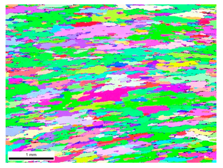
The characteristic microstructure of the as-received material is shown in Figure 2a. It comprises elongated grains with an average size of about 45 μm and numerous particles of the second phases. The multicomponent AA5083 system forms three groups of intermetallic compounds [14,15]: (i) constituent particles (Al + Fe, Mn, Si) with a size range of 0.5–10 μm; (ii) dispersions (Al + Mg, Mn, Cr, Zn) with a size range 0.05–0.5 μm; and (iii) precipitates (beta-phase Mg2Al3) of a nanometer size. Optical microscopy at large magnification (×1000) of the polished and unetched as-received material detected only the sufficiently large constituent particles and dispersions oriented along the rolling direction (Figure 2b). The high-temperature (530 °C) solution treatment produced a significantly coarser microstructure with an average grain size of about 800 μm (Figure 3). However, it preserved the orientation and the aspect ratio of the original grains. Such a treatment dissolved the precipitates and some of the dispersions into the aluminum matrix. This phase transformation was fixed by water quenching. To stabilize the microstructure, the solution-treated material was naturally aged for 10 days. For the overaged material condition, the microstructure was identical to that shown in Figure 3. Since optical microscopy could not unveil such small phases as precipitates, the final distribution of particles in the heat-treated materials was identical to the as-received material except that the dispersions looked slightly finer for the solution-treated condition and slightly coarser for the over-aged condition than that shown in Figure 2a.

3.1.2. Structures after Sc-ECAE

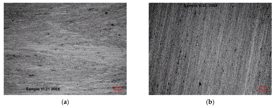
Figure 4a,b show optical micrographs after four-pass sc-ECAE via route D for material conditions I and II, respectively. In both cases, the individual grains could not be visualized, confirming significant structural refinement. The as-received material after sc-ECAE preserved the laminar structure of the original material (Figure 4a), as well as the oriented distribution of particles. In contrast, the microstructures of the fully recrystallized solution-treated condition looked more “isotropic” with a uniform distribution of particles. A similar microstructure was detected for the over-aged material. The grain microstructure of the sc-ECAE-processed samples were further examined by EBSD analysis. In general, the appearance for all the three conditions were identical. Typical EBSD results are illustrated in Figure 5a–c for the as-received material. The estimated grain size was 1.2 μm. The misorientation angles for most grain boundaries were in a range from 2° to 5°. Such low angle boundaries are characteristics of sub-grains rather than normally refined grains. The sub-grains occupied the larger parts of the parent grains having serrated high-angle boundaries. For the solution-treated and over-aged conditions, the misorientation angles were slightly lower than those shown in Figure 5c for the as-received material. A post-ECAE examination of the processed billets for the last two cases showed better surface finish without any flow localization or even shallow surface cracks.

3.1.3. Structures after Rolling of Sc-ECAE-Processed Materials

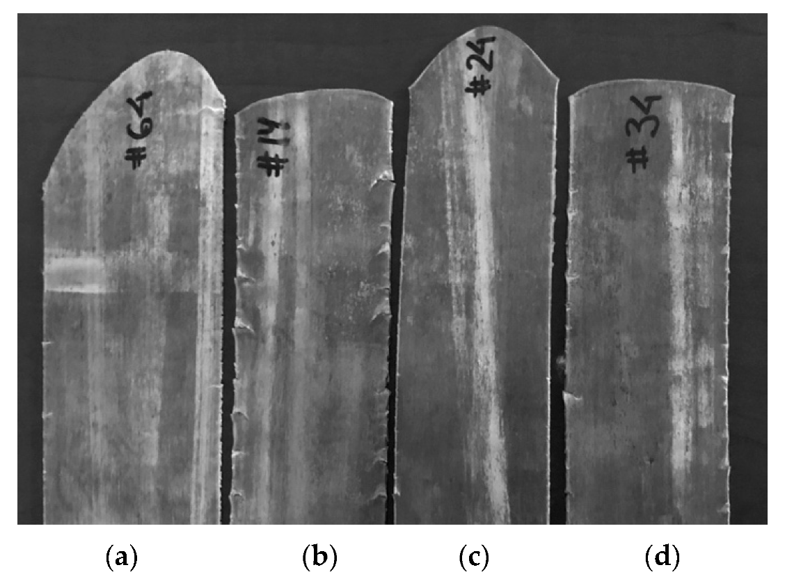
Rolling with different thickness reductions was performed for the three material conditions after sc-ECAE and for the as-received material without sc-ECAE. Samples for structural characterization and mechanical testing were selected after reductions of 50%, 75%, 87.5%, and 93.75%. Rolling to an 87.5% reduction did not develop any defects. At a reduction of 93.75%, edge cracks were observed depending on the initial material conditions (Figure 6). The biggest edge cracks were observed in the as-received material (sample #14), whereas the solution-treated material (sample #24) did not show any edge cracks.
Figure 7a,b demonstrate how additional rolling transformed a near-isotropic structure of the solution-treated material (see Figure 4b) into a fine, highly oriented laminar microstructure. Some results of the EBSD analysis of the sc-ECAE-processed material with subsequent rolling are presented in Figure 8a–c for the as-received condition after a reduction of 50%. During rolling, sub-grains, induced by semi-continuous ECAE, changed their equiaxed morphology into thin long grains with an average size of about 0.4 μm, whereas boundaries of the large original grains disappeared, intermetallic particles were fractured, and most low-angle boundaries were transformed into high-angle boundaries. The histogram in Figure 8c shows that, even after a relatively low rolling reduction of 50%, high-angle boundaries with angles of misorientation > 15° comprised about 65% of all of the grain boundaries.

3.1.4. Mechanical Properties

Table 1 shows hardness data (HRB) for the three material conditions after solution heat treatment, 10 days after treatment, and after four passes of sc-ECAE. The effect of the rolling reduction on the material hardness for the different conditions is shown in Figure 9 for the as-received material (curve 1), over-aged material + four (D) sc-ECAE passes (curve 2), as-received material + four (D) sc-ECAE passes (curve 3), and solution-treated material + four (D) sc-ECAE passes (curve 4). The best hardness was observed for the solution -treated material; as such, tensile tests after rolling were performed for this condition into the rolling direction. Results for the yield stress (YS; curve 1), ultimate tensile strength (UTS; curve 2), and relative elongation (EL; curve 3) are presented in Figure 10. For comparison, curve 4 shows the ultimate tensile strength of the as-received material after four (D) discontinuous ECAE passes at the same temperature of 250 °C.
A comparison of the mechanical properties of AA5083 achieved via the various processing routes and with a rolling reduction of 87.5% is presented in Table 2.

3.2. Semi-Continuous ECAE and Rolling of AZ31 Alloy

3.2.1. Sc-ECAE Processing of AZ31

During the past few years, an extensive volume of research was performed on ECAE of magnesium alloys [5]. In contrast to aluminum alloys, processing of magnesium alloys by ordinary, discontinuous ECAE appears to be much more difficult and less successful. Therefore, application of the sc-ECAE processing method to the magnesium-based alloy AZ31 presents significant interests. The typical microstructure of an industrially processed and annealed AZ31 material is shown in Figure 11. The grains are equiaxed with an average size of about 35 μm. Subsequent ECAE processing was carried out at temperatures of 200, 225, 250 275, and 300 °C with one, two, and three passes via route D, providing the effective strains of 1.15, 2.30, and 3.45, respectively. Because of significant refinement, the resultant microstructures were detected on polished and etched samples by SEM at a magnification of ×2000. Selected results are presented in Figure 12, Figure 13 and Figure 14.
Single-pass ECAE did not induce cracks at temperatures above 250 °C. Even one pass drastically changed the microstructure (Figure 12a). The microstructure was duplex, comprising a large number of fine fully recrystallized grains with an average size of about 2 μm and some larger grains oriented in the shear direction. Probably, these heavily elongated grains were remains of the larger original grains. For a temperature of 275 °C, the microstructure (Figure 12b) was much coarser with a large number of recrystallized grains of 8–10 μm. Therefore, it may be concluded that, for a single pass of ECAE, the optimal temperature of 250 °C does not complete dynamic recrystallization.
Two-pass ECAE processing was performed semi-continuously. No defects were observed at a temperature of 250 °C. Two passes provided a finer grain size (Figure 13a) than one pass at the same temperature (Figure 12a). At the higher temperature of 275 °C (Figure 13b), recrystallization in the bulk was completed. The previously observed duplex microstructure was absent and, instead, a uniform, equiaxed, and ultrafine-grained microstructure with an average grain size of about 2 μm covered the entire volume. An increase in temperature to 300 °C resulted again in a coarser and duplex microstructure. Three passes could be carried out without defects at a temperature of 300 °C; however, it did not lead to the further grain refinement. Therefore, two passes of sc-ECAE at a temperature of 275 °C were accepted as the optimal processing schedule for this material and the selected strain rate.

3.2.2. Rolling of Sc-ECAE-Processed AZ31

Preliminary experiments showed that rolling with high thickness reductions at temperatures below 300 °C led to through-thickness cracks. To eliminate such defects at the temperature of 300 °C, the typical rolling schedule comprised a series of steps with partial reductions of 12% or an effective strain of 0.14 per pass. After total reductions of 50%, 75%, and 87.5%, the material was reheated to the temperature of 300 °C for 10 min. The microstructural analysis for all reductions showed that rolling resulted in a degradation of the ultrafine-grained structure induced by ECAE and led to the development of coarser structures. As examples, Figure 14a,b demonstrate microstructures after rolling reductions of 50% and 93.75%, respectively. For comparison, similar rolling was performed on the original as-received material without any ECAE. All samples were subjected to tensile testing. The testing data together with the resultant grain sizes are shown in Table 3.

4. Discussion

As pointed out in the foregoing description, semi-continuous multi-pass ECAE provides significant technological advantages, resulting in much higher productivity and potentially lower costs than ordinary (or discontinuous) ECAE. Related to the structural evolution of the material, the actual difference between the two processing methods is the elapsed time intervals between successive passes. In the first case, for a fixed processing temperature and pressing speed, the shorter intervals increase the material temperature from pass to pass and reduce the recovery time. In the second case, much longer intervals, necessary for material cooling, reshaping, and preheating, preserve or maintain the processing temperature at a fixed value but significantly increase the recovery time. Due to adiabatic heating, these differences remain also for cold ECAE; however, single-pass processing would be identical in both cases. Specific temperature–time characteristics of semi-continuous and discontinuous ECAE provide different processing windows for the realization of various mechanisms of the structural evolution depending on material and processing conditions. The experimental results obtained for the two model alloys illustrate two limiting situations.
For AA5083, the primary grain refinement mechanism relates to the formation of new high/low-angle boundaries induced by severe shear strains. This mechanism requires the accumulation of strains and a high concentration of dislocations and other defects that may be effective only below the material’s recrystallization temperature. As processing and recrystallization temperatures of AA5083 are 250 °C and 325 °C, respectively, and the estimated adiabatic heating for aluminum alloys is about 50–70 °C per pass [16], the under-recrystallization threshold could be overcome after one to two passes. Thus, the practical way to stabilize the alloy microstructure during processing is through the control of precipitate particles by solution treatment and dynamic aging. Although AA5083 is a non-heat-treatable aluminum alloy, such an approach was often used for specific problems [17,18]. Usually, the solution treatment is performed at relatively low temperatures to prevent grain growth. However, in the present work, owing to the strong structural refinement during ECAE, a high solution temperature of 530 °C allowed the full dissolution of fine precipitates and, probably, some of the larger dispersoids [19]. These fine particles did not prevent the inevitable grain growth during heat treatment and, as a result, Figure 3 shows a very coarse microstructure of the alloy.
In comparison to the as-received material, the grain size of the solution-treated and over-aged materials was almost two orders of magnitude larger. This explains some of the differences in the observed experimental results. It is known that four ECAE passes via route D annihilate distortion of the material elements and restore the original macrostructure. For the originally rolled plate billets after four (D) passes, the resultant lamellae were oriented along the extrusion direction, but the patterns observed by optical microscopy depended on the original grain size and magnification. An “isotropic” or, as one may say, “vortex” pattern for the solution-treated material (Figure 4b) demonstrated the “micro-flow” of a few originally large recrystallized grains, whereas the laminar pattern for the as-received material (Figure 4a) showed “macro-flow” of an assembly of many oriented fine grains.
However, there is a big similarity between refined microstructures of semi-continuous ECAE. For all three conditions, the microstructures were formed by colonies of sub-grains of an average size of 1.2 μm and misorientation angles of 2–5° (Figure 5a–c) within large old grains with serrated boundaries. A development of such sub-grained microstructures demonstrates that an effect of adiabatic heating during short intervals was balanced by the stabilizing effect of numerous precipitate particles for the as-received and over-aged conditions and dynamic precipitation at sub-grain boundaries for the solution treated condition. These microstructures differed drastically from the microstructure of the same material and processing conditions after discontinuous ECAE comprising of ultrafine grains with an average size of 0.4 μm with misorientation angles more than 12° [20].
Additional warm rolling after semi-continuous ECAE led to a remarkable change of the refined microstructure. Even a moderate thickness reduction of 50% transformed sub-grains into fine elongated grains with mostly high-angle boundaries, whereas the old grains disappeared (Figure 8a–c). The pattern of “micro-flow” detected by the optical microscopy for the solution-treated and over-aged materials (e.g., Figure 7a) became identical to the as-received material (Figure 4a), confirming further structural refinement. With an increase in reductions, the long ultra-fine grains became very thin lamellae (Figure 7b), similar to those obtained via ordinary rolling.
The described structural evolution correlates with the mechanical properties of the alloy. In the original condition (Table 1), the highest hardness was observed for the as-received material and the lowest hardness for the over-aged material because of the presence of larger precipitates and other particles. Table 1 shows that, after 10 days, there was some natural aging of the solution-treated material. This material had the highest hardness after ECAE and following straining due to dynamic aging, which produced the finest precipitates. Such precipitate strengthening, together with dislocation strengthening and grain refinement, increased material hardness (Figure 9) and strength (Figure 10) during rolling. It is interesting to note that the ultimate tensile strength after semi-continuous ECAE + rolling of the solution-treated material was practically the same as for the as-received AA5083 after discontinuous ECAE + rolling in identical conditions (compare curves 2 and 4 in Figure 10). However, a comparison of both materials after sc-ECAE (curves 3 and 4 in Figure 9) shows that the solution-treated condition provided higher strength. Characteristics of ductility (Table 2) and workability (Figure 6) were also higher for the solution-treated material, confirming that dynamic aging occurred during processing and testing. In the results, the solution heat treatment significantly improved workability during ECAE, including the feasibility of processing at lower temperatures and during subsequent rolling, as well as improving the ductility of the final product.
It is informative to compare the mechanical properties of AA5083 achieved via different processing routes. Table 2 shows the yield stress (YS), ultimate tensile strength (UTS), and relative elongation (EL) of the ordinary AA5083 (temper H321, one-inch-thick material), the AA5083 after four (D) passes of discontinuous ECAE at a temperature 250 °C, and the same material after solution treatment + four (D) sc-ECAE passes at 250 °C. In both cases of ECAE, the increase in UTS was about 16% in comparison with temper H321. Subsequent warm rolling at a temperature of 150 °C provided a further increase in strength. For a reduction of 87.5%, the additional increase in UTS was 28%. Thus, the total improvement in UTS against temper H321 was almost 50%. The data in Table 2 indicate that post-ECAE rolling is not only a necessary step in the production route, but also an important step in the fabrication of high-strength lightweight materials.
There is an entirely different situation for AZ31. Historically, ECAE was firstly applied to aluminum alloys, for which the structural refinement to a sub-micrometer grain size was attained by multi-pass processing at temperatures below the recrystallization temperature. Later, this approach was extended to magnesium alloys. However, in contrast to aluminum alloys with a face-centered cubic crystallographic lattice, magnesium alloys having the hexagonal close-packed crystallographic structure are much less ductile and, therefore, they can be processed via severe plastic deformation only at higher temperatures. In principle, sub-micrometer structures in Mg alloys can be also achieved by ECAE at low temperatures with application of using high back pressures [21]. For example, to suppress fracture during multi-pass ECAE of AZ31 at temperatures below the recrystallization temperature of 200 °C, the magnitude of the back pressure should be greater than the material yield stress. This is highly impractical and difficult to realize at an industrial scale. Other suggestions such as using original stock materials with special crystallographic orientations [22] or relying on multi-step processing with continuously reduced temperatures [23] are equally complicated and impractical in a manufacturing environment.
On the other hand, Mg alloys are disposed to dynamic recrystallization (DRX), which takes place at specific ranges of strains, strain rates, and temperatures. This concept was recognized recently and clearly formulated in a review by Vinogradov et al. [5] (please note that the same approach was under development at EPM, Whitmore Lake, MI since 2015). When optimized, DRX can produce a minimum grain size of a few micrometers. As DRX depends strongly on recovery between passes, sc-ECAE is an effective processing technique for such optimization. In the present work, the strain rate was about 0.8 s−1, which matches the typical strain rates available at industrial hydraulic presses. The remaining variable parameters are the temperature and total imparted strain, equivalent to the number of passes necessary to achieve a stable, uniform, and minimum grain size. The results for AZ31 are summarized below.
1. The lowest processing temperatures without cracks and other defects were determined for one, two, and three passes. These critical temperatures increased with the number of passes.
2. For each pass, there was an optimal processing temperature, providing a minimum average grain size and a more uniform microstructure. The optimal temperatures also increased with the number of passes.
3. Even a single pass of ECAE significantly reduced the average grain size (Figure 12a,b). However, one pass did not complete the recrystallization process and, as a result, provided duplex microstructures comprising large grains.
4. Two-pass sc-ECAE processing at the optimal temperature of 275 °C completed the dynamic recrystallization of the material and produced a uniform, equiaxed, ultrafine-grained microstructure with an average grain size of about 2 μm (Figure 13b).
5. Additional passes did not contribute noticeably to the structural refinement but reduced productivity and increased cost.
These experimental observations conform to Vinogradov’s et al. previous conclusions [5].
For post-ECAE processing, there is also a minimum critical temperature for rolling without defects of the ECAE processed material to high rolling reductions, which are necessary for the fabrication of sheet and plate products. Since this temperature is higher than the optimal temperature of ECAE, if rolling is performed in a series of small deformations steps, and the intervals between reheating steps are kept sufficiently long, the rolled material will experience repeated dynamic and static recrystallizations, which, in turn, will destroy the ultrafine- to fine-grained microstructure, induce grain coarsening (Figure 14a,b), and lead to a degradation of properties. This was confirmed by tensile testing of the AZ31 samples in their original condition, after sc-ECAE, and after additional rolling with various thickness reductions (Table 3). In comparison to the original AZ31 alloy, sc-ECAE processing increased the ultimate tensile strength by 35%, the yield stress by 70%, and relative elongation by 22%. The balance between properties for this alloy after just two sc-ECAE passes was impressive: the average grain size was 2 μm, YS = 240 MPa, UTS = 335 MPa, and EL = 28%. A further comparison with similar data reported in a number of papers on ECAE processing of AZ31 [5] proves the significant advantages of semi-continuous ECAE. However, subsequent rolling leads to degradation of the ultrafine-grained microstructure and mechanical properties. For example, a thickness reduction of 75% increased the grain size from 2 μm to 8 μm and reduced the mechanical characteristics by 13% for YS, 20% for UTS, and 65% for EL. These results give rise to questions about the rationale and expediency of such combined processing routes.

5. Conclusions

1. The main advantage of multi-step semi-continuous ECAE is processing “pass-by-pass” without the need for billet reshaping and reheating. It provides a multifold increase in productivity and decrease in associated costs. With this modification, ECAE is transformed into an effective technique, which is similar to ordinary metal forming operations and can be adapted to common industrial practices including automated processing lines. Among the various known techniques of SPD, semi-continuous ECAE is an obvious alternative for practical applications, especially for the fabrication of bulk components at massive production scales.
2. Although the main focus of the development of semi-continuous ECAE was to understand material-specific processing conditions, our results presented additional options to control the prevailing temperature–time windows during SPD and, as such, the structural evolution of the resultant materials. In particular, the processing temperature was found to increase due to adiabatic heating, and the recovery time was reduced, thus changing the dynamics of the structural transformations. Related effects were identified for the aluminum alloy AA5083 as grain refinement via the strain-induced formation of new boundaries, and for the magnesium alloy AZ31 as grain refinement via dynamic recrystallization.
3. For AA5083, the summary effect of multi-pass semi-continuous ECAE for the as-received, solution-treated, and over-aged conditions resulted in the formation of sub-grained microstructure within the original grains. This is in contrast to the sub-micrometer grained microstructure produced by discontinuous ECAE. However, during subsequent rolling, these sub-grains were transformed into new grains similar to those obtained via ordinary ECAE. Owing to dynamic aging, the solution-treated condition provided the best properties compared to the other conditions evaluated, i.e., an equivalent high strength to ordinary ECAE but better levels of ductility and workability.
4. For AZ31, optimization of dynamic recrystallization by selection of the minimum processing temperature and total accumulated strains (for a fixed or, possibly, optimized strain rate) resulted in a very fine uniform microstructure and an excellent balance of properties using a low number of ECAE passes.

Author Contributions

Conceptualization, V.S.; investigation, V.S., S.V.R., N.M., and L.J.K.; methodology, S.V.R. and N.M.; project administration, V.H.H.; writing—original draft, V.S.; writing—review and editing, V.H.H. and L.J.K.

Funding

This research was funded by the US Army SBIR Office through the Project W911NF–16–0065.

Acknowledgments

The authors gratefully acknowledge funding by the US Army SBIR Office and the US Army Research Laboratory for its interest and support.

Conflicts of Interest

The authors declare no conflicts of interest.

Data Availability Statement

Requirements to reproduce these findings cannot be shared at this time as the data also form part of an ongoing study.

References

  1. Segal, V.M. Modes and processes of severe plastic deformation. Materials 2018, 11, 1175. [Google Scholar] [CrossRef] [PubMed]
  2. Ferrasse, S.; Segal, V.M.; Alford, F.; Strothers, S.; Kardocus, J.; Grabmeier, S.; Evans, J. Scale-up and commercialization of ECAE sputtering products with sub-microcrystalline structures. In Severe Plastic Deformation. Toward Bulk Products of Nanostructured Materials; Altan, B.S., Ed.; Nova Publishers: New York, NY, USA, 2006; pp. 585–601. [Google Scholar]
  3. Segal, V.M. Method and Apparatus for Intensive Plastic Deformation of Flat Billets. U.S. Patent No. 5,850,755, 22 December 1998. Available online: http://patft.uspto.gov/netacgi/nph-Parser?Sect1=PTO1&Sect2=HITOFF&d=PALL&p=1&u=%2Fnetahtml%2FPTO%2Fsrchnum.htm&r=1&f=G&l=50&s1=5850755.PN.&OS=PN/5850755&RS=PN/5850755 (accessed on 16 September 2019).
  4. Segal, V.M. Method of Equal Channel Angular Extrusion. U.S. Patent Application No. 20,170,320,115, 9 November 2017. Available online: http://appft.uspto.gov/netacgi/nph-Parser?Sect1=PTO2&Sect2=HITOFF&u=%2Fnetahtml%2FPTO%2Fsearch-adv.html&r=142&f=G&l=50&d=PG01&s1=segal.IN.&p=3&OS=IN/segal&RS=IN/segal (accessed on 16 September 2019).
  5. Vinogradov, A.; Serebryany, V.N.; Dobatkin, S.V. Tailoring microstructure and properties of fine-grained magnesium alloys by severe plastic deformation. Adv. Eng. Mater. 2018, 20, 1700785. [Google Scholar] [CrossRef]
  6. Segal, V.M. Equal channel angular extrusion (ECAE). In Severe Plastic Deformation Technology; Rosochowsky, A., Ed.; Whittles Publishing Limited: Dunbeath, UK, 2017; pp. 1–40. [Google Scholar]
  7. Luri, R.; Luis, C.J.; Leon, J.; Sebastian, M. A new configuration for equal channel angular extrusion dies. J. Manuf. Sci. Eng. 2006, 128, 860–865. [Google Scholar] [CrossRef]
  8. Dupuy, L.; Blandin, J.J.; Rauch, E.F. Structural and mechanical properties in AA5083 processed by ECAE. Mater. Sci. Tech. 2000, 16, 1256–1258. [Google Scholar] [CrossRef]
  9. Jin, H. Improvement superplasticity in AA5083 by equal-channel angular extrusion and rolling. Mater. Sci. Tech. 2017, 33, 1696–1702. [Google Scholar] [CrossRef]
  10. Gzyl, M.; Rosochowski, A.; Boczkal, S.; Olejnik, L.; Katimon, M.N. Producing high-strength metals by I-ECAP. Adv. Eng. Mater. 2016, 18, 219–223. [Google Scholar] [CrossRef]
  11. Ma, A.; Jiang, J.; Saito, N.; Ichnori, S.; Yuan, Y.; Nishida, Y. Improving both strength and ductility of a Mg alloy through a large number of ECAP passes. Mater. Sci. Eng. A 2009, 513, 122–1217. [Google Scholar] [CrossRef]
  12. Jin, L.; Lin, D.; Mao, D.; Zeng, F.; Chen, B.; Ding, W. Microstructure evolution of AZ31 Mg alloy during equal-channel angular extrusion. Mater. Sci. Eng. A 2006, 423, 247–252. [Google Scholar] [CrossRef]
  13. Figueiredo, R.B.; Aguilar, M.T.P.; Cetlin, P.R.; Langdon, T.G. Processing magnesium alloys by severe plastic deformation. IOP Conf. Ser. Mater. Sci. Eng. 2014, 63, 012171. [Google Scholar] [CrossRef] [Green Version]
  14. McQuenn, H.J.; Spigarelli, S.; Kassner, M.E.; Evangelista, E. Hot Deformation and Processing of Aluminum Alloys; CRC Press: Boca Raton, FL, USA, 2011. [Google Scholar]
  15. Lee, C. Thermo-Mechanical Processing of an Al-Mg Alloy. Ph.D. Thesis, University of London, Imperial College, London, UK, 1989. [Google Scholar]
  16. Segal, V.M.; Beyerlein, I.J.; Tome, C.N.; Chuvil’deev, V.I.; Kopylov, V.I. Fundamentals and Engineering of Severe Plastic Deformation; Nova Science Publishers: New York, NY, USA, 2010. [Google Scholar]
  17. Kim, S.J.; Jang, S.K. Effects of solution heat treatment on corrosion resistance of 5083F alloy. Trans. Non-Ferr. Meter. Soc. China 2009, 19, 887–891. [Google Scholar] [CrossRef]
  18. Huang, C.; Wu, Z.; Huang, R.; Wang, W.; Li, L. Mechanical properties of AA5083 in different tempers at low temperatures. IOP Conf. Ser. Mater. Sci. Eng. 2017, 279, 012002. [Google Scholar] [CrossRef]
  19. Sivam, S.P.S.S.; Kumar, A.L.; Moorthy, K.S.; Kumar, R. Investigation exploration outcome of heat treatment on corrosion resistance of AA5083 in marine applications. Int. J. Chem. Sci. 2016, 14, 453–460. [Google Scholar]
  20. Jin, H.; Gallerneault, M.; Segal, V.M.; Young, P.J.; Lloyd, D.J. Grain structure and texture in aluminum alloy AA5083 after equal angular extrusion, warm rolling and subsequent annealing. Mater. Sci. Tech. 2011, 27, 789–792. [Google Scholar] [CrossRef]
  21. Lapovok, R.Y. The positive role of back-pressure in equal-channel angular extrusion. Mater. Sci. Forum 2006, 503, 37–44. [Google Scholar] [CrossRef]
  22. Biswas, S.; Dhinwal, S.S.; Suwas, S. Room temperature equal channel angular extrusion of pure magnesium. Acta Mater. 2010, 58, 3247–3261. [Google Scholar] [CrossRef]
  23. Foley, D.C.; Al-Maharbi, M.; Hartwig, K.T.; Karaman, I.; Kecskes, L.J.; Mathaudhu, S.N. Grain refinement vs. crystallographic texture: Mechanical anisotropy in magnesium alloy. Scr. Mater. 2011, 64, 193–196. [Google Scholar] [CrossRef]
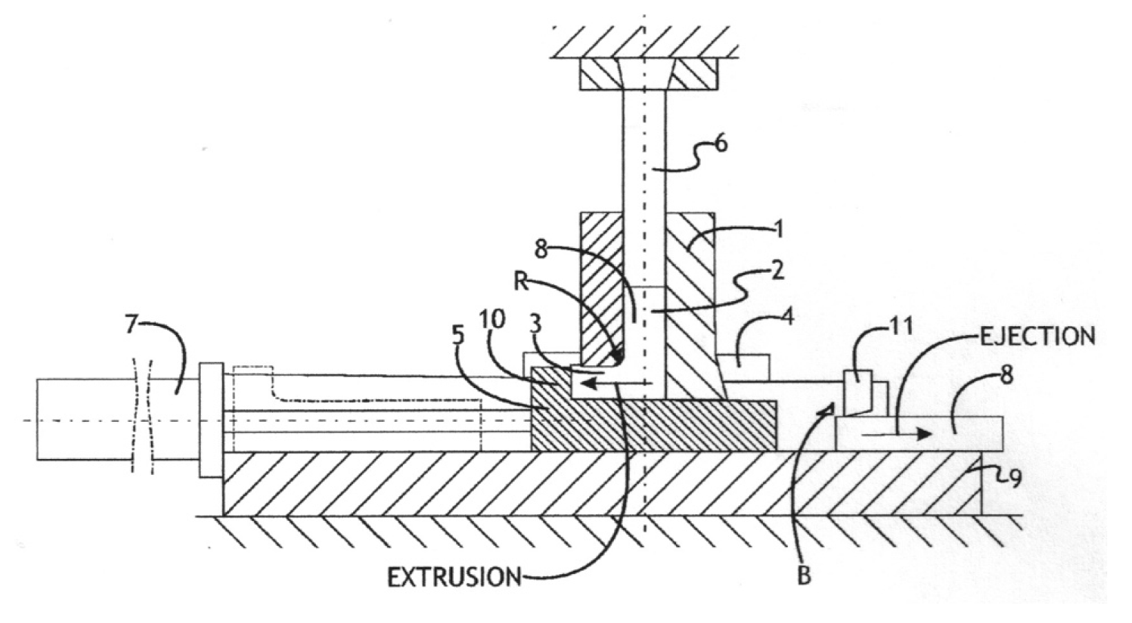
Figure 1. Schematic of the tooling design for semi-continuous equal-channel angular extrusion (sc-ECAE).
Metals 09 01035 g001
Figure 2. (a) Optical microstructure (scale bar is 100 μm) and (b) distribution of particles (scale bar is 10 μm) in the as-received aluminum alloy AA5083.
Metals 09 01035 g002
Figure 3. Electron backscatter diffraction (EBSD) color-coded orientation map of the solution-treated AA5083 (step size is 5 μm).
Metals 09 01035 g003
Figure 4. Optical microstructure of AA5083 after four (D) passes of sc-ECAE for (a) the as-received material (scale bar is 30 μm; lamellae are oriented in the rolling/extrusion direction) and (b) isotropic macrostructure of the solution-treated material (scale bar is 50 μm).
Metals 09 01035 g004
Figure 5. EBSD analysis of the as-received AA5083 after four (D) sc-ECAE passes: (a) image quality map (step size is 70 nm); (b) color-coded orientation map; and (c) misorientation angle histogram (5° is set as the minimum). Lamellae in (a,b) are oriented along the extrusion direction.
Metals 09 01035 g005
Figure 6. Edge cracks in AA5083 after rolling reduction of 93.75%: (a) as-received material; (b) as-received material + four (D) sc-ECAE passes; (c) solution-treated material + four (D) sc-ECAE passes; and (d) over-aged material + four (D) sc-ECAE passes.
Metals 09 01035 g006
Figure 7. Optical microstructure of the solution-treated AA5083 + four (D) sc-ECAE passes after (a) rolling reductions of 50% and (b) rolling reductions of 87.5% (scale bars are 50 μm). Lamellae are oriented in the rolling direction.
Metals 09 01035 g007
Figure 8. EBSD analysis of the as-received AA5083 after four (D) sc-ECAE passes + 50% rolling reduction: (a) image quality map (step size is 25 nm); (b) color-coded orientation map; and (c) misorientation angle histogram (5° is set as the minimum). Lamellae in (a,b) are oriented in the rolling direction.
Metals 09 01035 g008
Figure 9. Effect of rolling reduction on hardness of AA5083: 1—as-received material; 2—over-aged material + four (D) sc-ECAE passes; 3—as-received material + four (D) sc-ECAE passes; 4—solution-treated material + four (D) sc-ECAE passes.
Metals 09 01035 g009
Figure 10. Effect of rolling reduction on yield stress (YS), ultimate tensile strength (UTS), and relative elongation (EL) of AA5083: 1—YS of the solution-treated material + four (D) sc-ECAE passes; 2—UTS of the solution-treated material + four (D) sc-ECAE passes; 3—EL of the solution treated material + four (D) sc-ECAE passes; 4—UTS after four (D) discontinuous ECAE passes of the as-received material.
Metals 09 01035 g010
Figure 11. Original microstructure of the magnesium alloy AZ31.
Metals 09 01035 g011
Figure 12. Microstructures of AZ31 after one ECAE pass at temperatures of 250 °C (a) and 275 °C (b). The large grains in (a) are oriented along the extrusion direction.
Metals 09 01035 g012
Figure 13. Microstructures of AZ31 after two sc-ECAE passes at temperatures of 250 °C (a) and 275 °C (b). The large grains in (a) are oriented along the extrusion direction.
Metals 09 01035 g013
Figure 14. Isotropic microstructures of AZ31 after two sc-ECAE passes + rolling with reductions of 50% (a) and 87.5% (b).
Metals 09 01035 g014
Table 1. Hardness (HRB) of aluminum alloy AA5083. Sc-ECAE—semi-continuous equal-channel angular extrusion.
Material ConditionAs-Received MaterialSolution-Treated MaterialOver-Aged Material
Original hardness32.224.222.2
Hardness after 10 days32.226.222.2
Hardness after sc-ECAE47.553.844.5
Table 2. Mechanical properties of AA5083. YS—yield stress; UTS—ultimate tensile strength; EL—elongation.
Processing RouteYS (MPa)UTS (MPa)EL (%)
As-received AA5083 H32122831716
As-received AA5083 + four (D) sc-ECAE passes29036618
Solution-treated AA5083 + four (D) sc-ECAE passes29637018
As-received AA5083 + four (D) sc-ECAE passes + 87.5% rolling reduction 45047510
Solution-treated AA 5083 + four (D) sc-ECAE passes + 87.5% rolling reduction45547014
Table 3. Grain size and tensile properties of magnesium alloy AZ31.
Material ConditionsAverage Grain Size (μm)Yield Stress (MPa)Ultimate Tensile Strength (MPa)Elongation (%)
As-received, annealed3514024822
As-received + rolling with reductions:----
50%1320027819
75%919027518
87.5%816527516
93.75%617028015
As-received + two (B) sc-ECAE passes224033528
As received + two (B) sc-ECAE passes + rolling with reductions:----
50%1517027022
75%821028017
87.5%618528015
93.75%618028213