Article

Initial Transfer Behavior and Solidification Structure Evolution in a Large Continuously Cast Bloom with a Combination of Nozzle Injection Mode and M-EMS

1
School of Metallurgical and Ecological Engineering, University of Science and Technology Beijing, Beijing 100083, China
2
Technical Quality Center, Xining Special Steel Co., Ltd., Xining 810005, China
*
Authors to whom correspondence should be addressed.
Metals 2019, 9(10), 1083; https://doi.org/10.3390/met9101083
Submission received: 6 September 2019 / Revised: 3 October 2019 / Accepted: 3 October 2019 / Published: 8 October 2019
(This article belongs to the Special Issue Mathematical Modeling and Simulation in Ironmaking and Steelmaking)

Abstract

:
A three-dimensional numerical model combining electromagnetic field, fluid flow, heat transfer, and solidification has been established to study the effect of nozzle injection mode and mold electromagnetic stirring (M-EMS) on the internal quality of a continuously cast bloom. The model is validated by measured data of the magnetic flux density along the stirrer center line. According to the simulation and experimental results, M-EMS can introduce a horizontal swirling flow ahead of the solidification front, promoting the superheat dissipation of molten steel and columnar to equiaxed transition (CET). As the stirring current increases from 0 to 800 A, the superheat at the mold exit in the bloom center decreases by 1.9 K for the single-port nozzle case and 3.8 K for the five-port nozzle case. The resulting increase in the equiaxed crystal ratio is about 5.65% and 4.06%, respectively. In comparison, the injection mode shows a more significant influence on the heat transfer and solidification structure in the bloom under the present casting conditions. The superheat at the mold exit in the bloom center decreases by 5.1–7.7 K as the injection mode changes from a single-port nozzle to a five-port nozzle, and the increase in the equiaxed crystal ratio ranges between 14.8% and 17%. It is found that the flow velocity of the molten steel in front of the solidification interface for the five-port nozzle is higher than that for the single-port nozzle regardless of the M-EMS power. The washing effect here reinforces both the heat exchange through the solidification interface and the dendrite re-melting or fragmenting, stimulating the formation of an equiaxed crystal at the bloom center. In addition, it is observed that both the central shrinkage and carbon segregation have decreased with the five-port nozzle plus M-EMS. This suggests that the combined application of a five-port nozzle and M-EMS can effectively improve the internal quality of large bloom castings.

1. Introduction

The quality of special rolled steel products is closely related to the control effect of the as-cast macrostructure and composition uniformity. Bloom continuous casting is the basic process for the production of large-section special steel bars, and most defects affecting the special steel quality in the continuous casting (CC) process are associated with metallurgical behavior in the mold, which mainly depends on the flow pattern, controlled by a submerged entry nozzle (SEN) and mold electromagnetic stirring (M-EMS) [1,2]. At present, M-EMS is a widely accepted technique used to optimize molten steel flow in bloom casting; the swirling flow driven by the rotating electromagnetic force improves the heat transfer at the solidification front, which has been proven to enhance the columnar to equiaxed transition (CET) during solidification. Moreover, M-EMS can reduce the center segregation defects to improve the product quality [3]. The impingement depth of the molten steel under the single-port nozzle is usually very large, which is not beneficial for the flotation removal of non-metallic inclusions. Due to the complexity of transport phenomena in a combination of the nozzle injection mode and M-EMS, it is difficult to investigate the melt flow and solidification through physical experiments and plant measurements. Therefore, the development of a numerical simulation method makes it possible to achieve a forward-looking evaluation of the action pattern of nozzle type, and then guide the production process.
Ayata et al. [4] developed a new nozzle with an air-cooling system and EMS on the upper part of the nozzle to reduce the temperature of the molten steel. However, the space of the continuous casting platform limits the application of this technique. Yokoya et al. [5] applied swirling blades to the top of the single-port nozzle to form a horizontal swirling flow for the purposes of achieving superheat dissipation. Because the blade structure is complicated and easily washed away or eroded by liquid steel, which may lead to a nozzle block during service, the service life cannot be guaranteed. Sun et al. [6] compared the flow and solidification behavior of molten steel in different nozzle types, and found that the four-furcated tangential nozzle can produce a horizontal swirling flow of molten steel in the mold, obtaining a metallurgical effect similar to that of M-EMS. However, the higher manufacturing cost due to the complex structures is a factor limiting the wide application of this technology. Wang et al. [7] applied a 3D numerical model to analyze the molten steel flow with M-EMS for a round strand, in which the operational parameters for the current, frequency, and nozzle submerged depth were determined for an improved round strand quality. Yu and Zhu [8] simulated the flow field, the distribution of the temperature field, and the inclusion trajectory in the round billet, and conducted an industrial test to adjust the stirring parameters of the M-EMS, which significantly improved the shrinkage and surface defects of the strand. Li et al. [9,10] established a coupled model of electromagnetic, flow, heat transfer, and solidification under the low Reynolds number model of bloom casting. The electromagnetic field under different stirring parameters was revealed, and it was seen that increasing the current intensity will not only promote superheat dissipation, but also cause slow growth in the region of shell solidification. Sun and Zhang [11] established 3D and 2D hybrid models to simulate fluid flow and solute transport during the bloom casting under electromagnetic stirring. It was found that the solute enrichment of the molten steel caused positive segregation, and the washing effect caused by electromagnetic stirring caused negative segregation in the strand.
Up to now, there have been few reports that focus on the effect of a combination of different injection modes and M-EMS on the metallurgical transport behavior and macroscopic morphology of strand castings. In this study, a 3D coupling numerical model of electromagnetic, flow, heat transfer, and solidification in the mold region is established by taking the example of a 410 mm × 530 mm bloom casting for carbon 45 steel bar production. The 3D coupling analysis has been carried out together with industrial casting experiments, which is expected to reveal the influence of the stirring current intensity in the conventional single-port nozzle and a newly designed five-port nozzle injection modes on the macro-solidification structure of large bloom castings.

2. Model Descriptions

The carbon 45 steel is manufactured with process 110 t electric arc furnace → IF ladle refining → VD vacuum degassing → 3-strand continuous casting machine → hot rolled bars, in which there are popular as-cast defects like center shrinkage cavity and carbon segregation. The geometry of the single-port nozzle and the new five-port nozzle are shown in Figure 1, where the center line of the side holes of the five-port nozzle is at an angle of 45° to the center line of the wide face of the bloom. The schematic diagram of the bloom continuous casting mold with M-EMS discussed in this paper is shown in Figure 2a, and the location of the M-EMS is given in Figure 2b. The model of M-EMS mainly includes molten steel, a stirring coil, a copper tube mold, an iron core, and an air region (not shown). The M-EMS is a 12-coil, three-pair winding structure; the origin of the coordinates is at the center of the mold meniscus. The inner diameter is 1050 mm, the outer diameter is 1490 mm, the height is 590 mm, the wall thickness of the copper tube is 33 mm, the center of the M-EMS is 480 mm from the meniscus, and the stirring mode is continuous horizontal rotation stirring.

2.1. Basic Assumptions of the Model

In order to reasonably describe the complex and mutually influential metallurgical physical phenomena in the mold, the basic assumptions are as follows:
  • During the electromagnetic stirring process, the magnetic Reynolds number of the molten steel is small, ignoring the influence of the molten steel flow on the magnetic field.
  • Under low-frequency agitation, the electromagnetic field can be regarded as a magnetic quasi-static field, ignoring the displacement current, and using the time-average electromagnetic force instead of the transient value.
  • Ignoring the anisotropy of the material, it is considered that the molten steel, copper tube, and iron core are all isotropic materials, and physical properties such as conductivity and magnetic permeability are treated as constants.
  • The low-Reynolds number k ε model is adopted to simulate the turbulence in the mold, and the mushy zone is treated as a porous medium, where the flow obeys Darcy’s law.
  • The molten steel is assumed to be an incompressible Newtonian fluid. The viscosity, specific heat, and thermal conductivity are assumed to be constants.
  • The influence of mold oscillation and mold curvature on the fluid flow is not considered.

2.2. Governing Equations

2.2.1. Electromagnetic Field

At a low frequency of M-EMS, the Maxwell’s equations of electromagnetic field can be found from Li et al. [12]:
Gauss’s law for magnetism:
× B = 0 .
Ampere’s law:
J = × B μ .
Faraday’s law:
× E = B t .
Ohm’s law:
J = σ ( E ) .
The average electromagnetic force is calculated by the following:
F E = 1 2 R e ( J × B ) ,
where B is the magnetic induction density; J is the current-induced intensity in the melt; μ is the magnetic permeability; E is the electric field strength; and σ is the electrical conductivity.

2.2.2. Flow and Solidification

  • The continuity equation is as follows:
    ( ρ u j ) x j = 0 ,
    where ρ is the density of steel and u j is the velocity component in the direction x j of the stream.
  • The momentum equation is as follows:
    ρ ( u i u j ) x j = ( P ) x j + x j ( μ e f f u i x j ) + x i ( μ e f f u j x i ) + ρ g + F B + F E + S P ,
    where P is the pressure and μ e f f is the effect viscosity coefficient, which can be defined as follows:
    μ e f f = μ l + μ t ,
    where μ l is the laminar viscosity and μ t is the turbulent viscosity, which can be defined as follows:
    μ t = ρ f μ C μ k 2 ε ,
    where f μ and C μ are constants in the low Reynolds number turbulence two-equation model, k is the turbulent energy, and ε is the turbulent energy dissipation rate, which can be calculated by the low Reynolds number turbulence two-equation model [13]. F E is the electromagnetic force and F B is the thermal buoyancy, defined as follows:
    F B = ρ g β ( T T l ) ,
    where β is the thermal expansion coefficient, T is the temperature, and T l is the liquidus temperature. S P accounts for the phase interaction force within the mushy zone, which can be described by Darcy’s law:
    S P = ( 1 f l ) 2 ( f l 3 + 0.001 ) A m u s h ( u u p ) ,
    where A m u s h is a mushy zone constant that has a great influence on the calculation of flow and solidification; in this study, it is set to 5 × 10⁸ to obtain the most accurate results.   u p is the casting speed; f l is the liquid fraction and is given by the lever rule in the mushy zone as follows:
    f l = 1 f s = { 1 T T l T T s T l T s T s < T < T l 0 T T s ,
    where T s is the solidus temperature and f s is the solid fraction.
  • The energy equation is as follows:
    ρ ( u i H ) x j = x i ( k e f f T x i ) ,
    where H is the total enthalpy, defined as follows:
    H = h r e f + T r e f T c p d T + f l L ,
    where h r e f is the sensible enthalpy, c p is the specific heat, L is the latent heat of molten steel solidification, and k e f f is the effective thermal conductivity, which can be defined as follows:
    k e f f = k l + c p μ t P r t ,
    where k l is the thermal conductivity and P r t is the turbulent Prandtl number, which is set to 0.9 [14].

2.3. Boundary Conditions

2.3.1. Electromagnetic Field

  • Three pairs of coil windings are loaded with a three-phase alternating current; the phase difference of each phase is 120°.
  • The magnetic flux lines are parallel to the boundary at the external surfaces of the surrounding air unit.
  • Insulation boundary conditions are imposed between the electromagnetic stirrer coil and the iron core.

2.3.2. Flow and Solidification

  • Inlet of nozzle: the inlet velocity is derived from the mass conservation relationship of the bloom casting. The inlet temperature is the casting temperature, and the turbulent kinetic energy and turbulent dissipation rate at the inlet are calculated according to the empirical formulas [15]:
    k = 0.01 v i n 2
    ε = 2 k 1.5 / D ,
    where v i n is the velocity of the nozzle inlet and D is the diameter of the nozzle.
  • Outlet of computation domain: the fully developed flow condition is adopted, where the normal gradients of all variables are set to 0.
  • Free surface: Considering the insulation effect of the mold flux, the free surface is set to be adiabatic and the shear stress is 0.
  • Wall surface: a non-slip wall surface is adopted and the nozzle wall is set to adiabatic. The heat flux boundary condition is applied on the mold zone according to Li [10]:
    q s = 2,680,000 b L v c ,
    where q s is the heat flux density. The convective heat transfer boundary condition is imposed on the secondary cooling zone. The integrated heat transfer coefficient is calculated by [10]:
    (Water spray region)
    h 1 = 420 w 0 0.351 ;
    (Air-mist spray region)
    h 2 = 116 + 10.44 w 1 0.851 ,
    where w 0 and w 1 are the cooling water volume flow rate with a unit of L·m−2·s−1 and L·m−2·min−1, respectively.

2.4. Numerical Solution Procedure

The electromagnetic field is calculated by the finite element software Ansys Maxwell (ANSYS, Inc., Canonsburg, PA, USA), and the time-average electromagnetic force is extracted by the coordinate interpolation algorithm. The fluid flow, heat transfer, and solidification of molten steel in the continuous casting process are simulated by finite volume software ANSYS Fluent16.0 (ANSYS, Inc., Canonsburg, PA, USA), and the data of electromagnetic forces are imported into the momentum equation as source terms by user-defined functions. For the calculation model, the casting direction is along the positive direction of the Z axis; the X and Y directions are parallel to the narrow and wide faces of the bloom, respectively. Tetrahedral cells are used for a fine mesh to the electromagnetic model, with a total cell number of 350,706. The grids in the calculation domain are around 3,500,000, the near wall grids are refined to accurately predict the initial solidification, and the finest mesh is approximately 1.5 mm in the solidification mushy zone. The SIMPLE algorithm is adopted for the discrete governing equations, and the discretization scheme of momentum is second order upwind. The calculation is assumed to achieve convergence when the residual for energy is smaller than 1 × 10⁻⁶ and others are smaller than 1 × 10⁻⁴. The calculation of the loaded and unloaded electromagnetic forces to convergence requires 360 and 240 h, respectively.
In order to explore the effects of the combination of the injection mode and the M-EMS on the internal quality of the continuously cast bloom, four different current intensities at the same frequency of 1.5 Hz were selected for the numerical simulation: 0 A, 300 A, 600 A, and 800 A. Table 1 shows the main chemical components of the steel in a plant trial. The main dimensions and material physical properties used in the current study are listed in Table 2.

3. Results and Discussion of Calculation

3.1. Electromagnetic Field Simulation Analysis

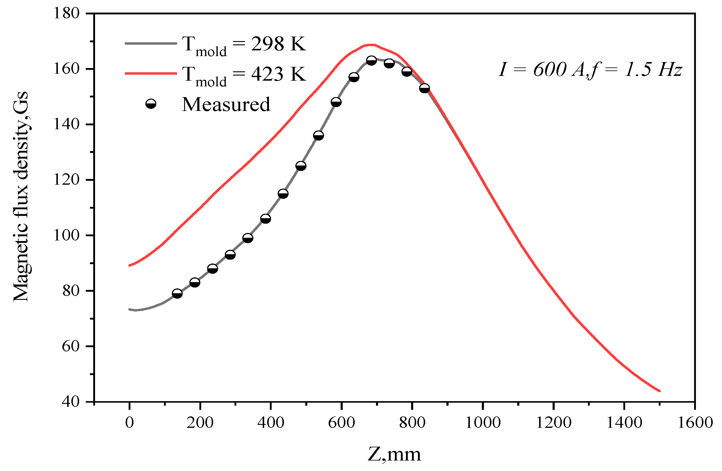
Figure 3 shows the magnetic flux density distribution along the casting direction of the central line of the strand at different mold copper temperatures (room temperature is 298 K; the on-line operation temperature is 423 K) when the current is 600 A and the frequency is 1.5 HZ. The magnetic flux density on the centerline of the mold was measured by a HT201 Gauss meter (HengTong Magnetoelectricity CO., LTD, SH, China) during two sequence casting intervals in production. It is evident that the model calculation results are in good agreement with the measured values when the temperature of copper tube is 298 K, which proves that the model is accurate and reliable. Considering that the copper tube temperature is higher and the conductivity is lower in actual production, the copper tube conductivity at 423 K is adopted for subsequent calculations.
When the current frequency is 1.5 Hz, the magnetic flux density distribution on the central axis and at the center point of the stirrer at different current intensities are shown in Figure 4a,b, respectively. This indicates that, as the current intensity increases, the magnetic flux density at the same position increases significantly, and the maximum magnetic flux density appears when Z = 693 mm. When the current intensities are 300 A, 400 A, 500 A, 600 A, 700 A, and 800 A, the magnetic flux density in the center of stirrer is 70.5 Gs, 94.1 Gs, 117.6 Gs, 141.1 Gs, 164.6 Gs, and 188.1 Gs, respectively. Since the magnetically saturated effect of the iron core was not considered in the numerical model, the magnetic flux density at the center point is assumed to increase by 23.5 Gs, while the current intensity increased by 100 A.

3.2. Simulation Analysis of Flow, Heater Transfer, and Solidification

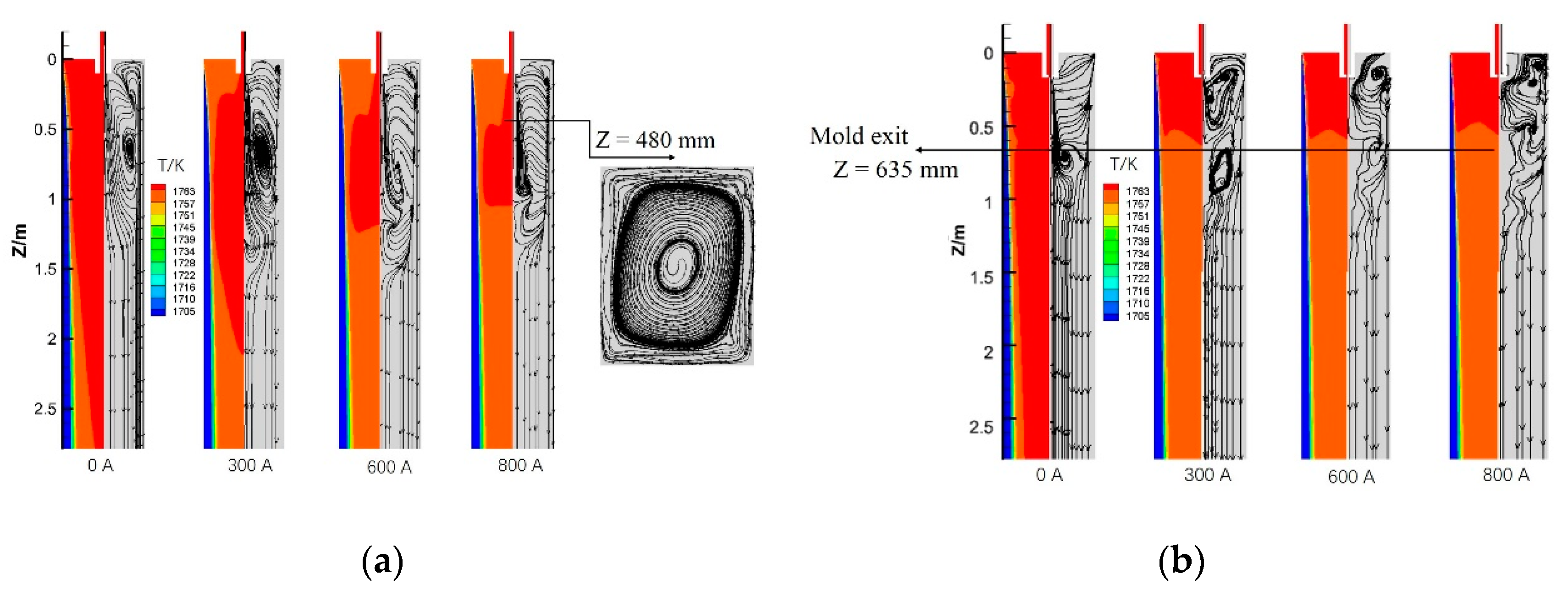
Figure 5 shows the flow streamline and temperature distribution over the wide symmetry plane (X = 0 m) of the two kinds of injection modes at different current intensities. After the M-EMS is applied, the rotating electromagnetic force causes a horizontal swirling flow, which prevents the downward movement of the liquid steel. A weaker secondary circulation flow is observed in the lower part of the mold, which will enhance with the increase of the current intensity. The increase of the current intensity is beneficial to the molten steel remaining in the upper recirculation zone. The five-port nozzle has an active upper recirculation zone thanks to the side holes’ jet flow, which is beneficial for the removal of bubbles and inclusions [17].
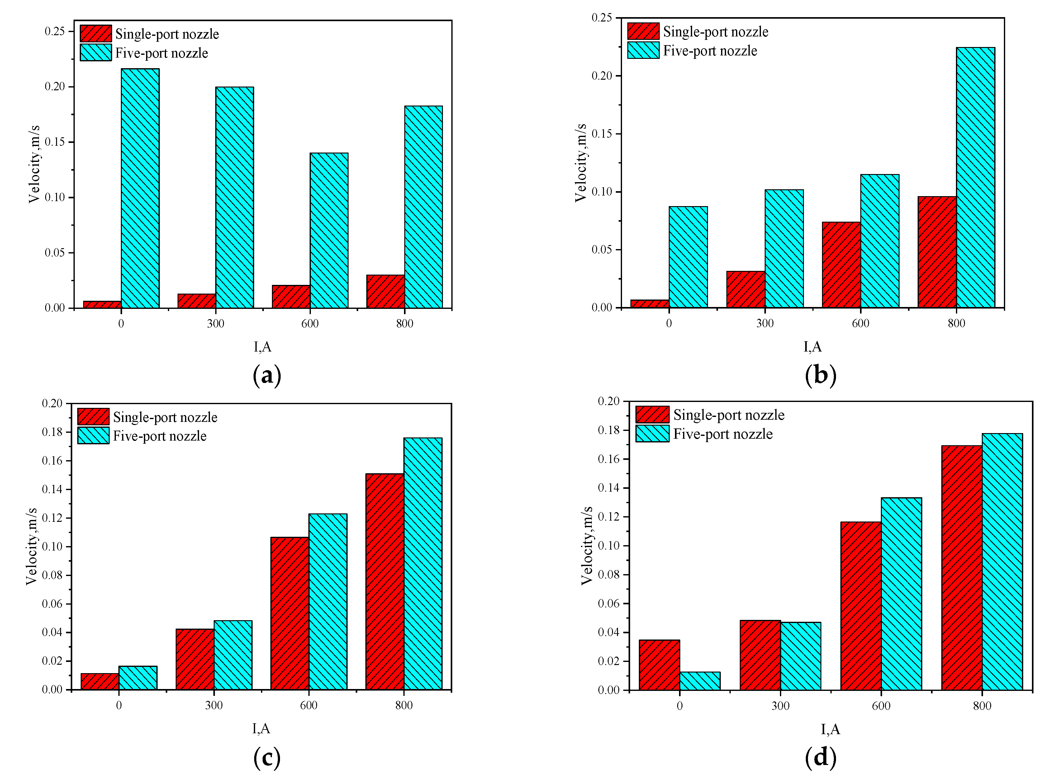
Figure 6 indicates the maximum velocity at the solidification front of each mold cross section of different current intensities. The washing effect of the molten steel at the solidification front helps to melt the frontier of the dendrite; then the broken dendrites will flow with the molten steel, which can enhance the nucleation of equiaxed crystals [18]. From Figure 6b–d, we see that, as the current intensities increase, the horizontal swirling flow generated increases as well, which results in an increase in the size of holes, due to the washing velocity of the solidification front. Figure 6a shows the jet flow zone of the side holes. As the current intensity increases to 600 A, the induced horizontal swirling flow can effectively slow down both the velocity at the port exit and the washing effect. However, when it is increased to 800 A, there appears to be an enhanced washing effect due to the excessive swirling flow. For the contribution of high outflow velocity from the side holes, the washing effect of the five-port nozzle on the solidification front is much more powerful than that of the single-port nozzle, which is favorable for generating free nucleation.
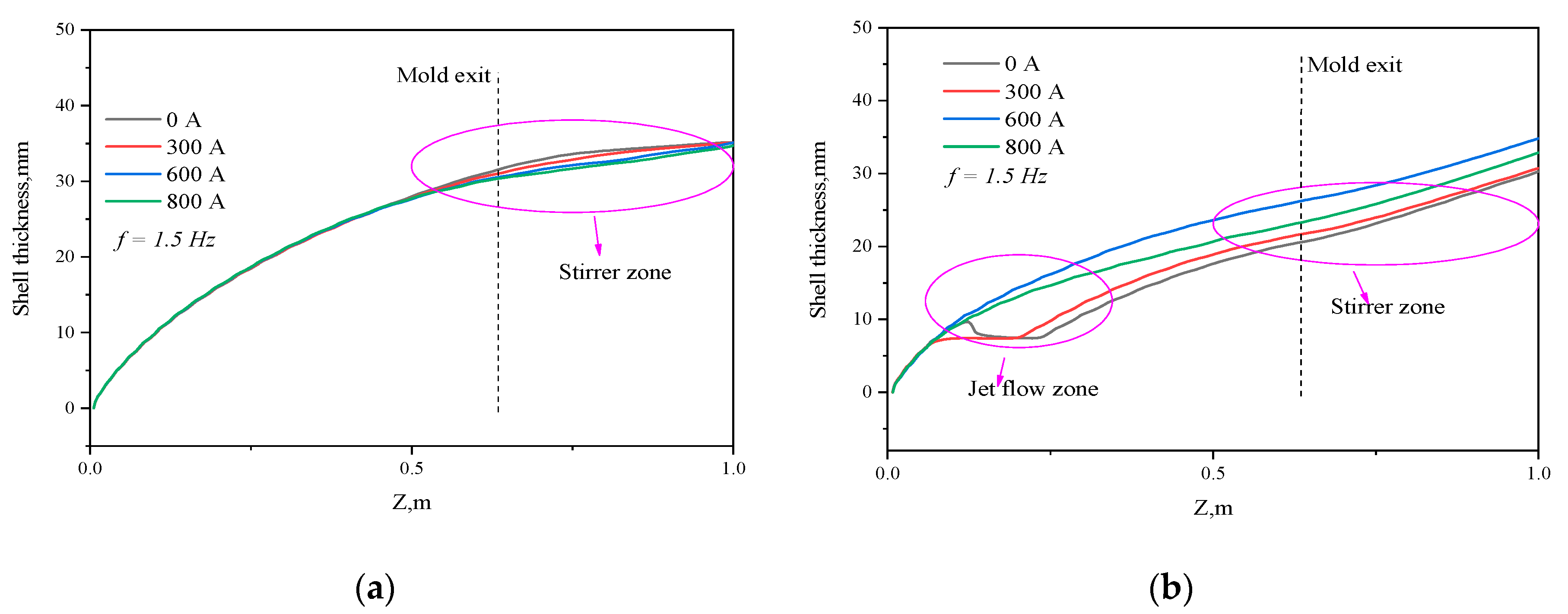
The distribution of the shell thickness calculated in the impact zone along the casting direction under the different current intensities of the two nozzle injection modes is shown in Figure 7, in which the solidification front is marked where the liquid fraction is 0.3 [19]. When the current intensities are 0 A, 300 A, 600 A, and 800 A, respectively, and a single-port nozzle has been installed, the shell thickness at the mold exit is 31.5 mm, 31.0 mm, 30.5 mm, and 30.4 mm, respectively. The horizontal swirling flow of molten steel created by M-EMS increases with the current intensity, which leads to a thinner growth of solidified shells near the mold exit. However, when the current intensities are the same as above but a five-port nozzle has been adopted, the shell thickness at the mold exit is 20.6 mm, 21.7 mm, 26.2 mm, and 23.3 mm, respectively. As the current intensity increases, the washing of the solidification front by the side hole jet flow initially decreases, but this is followed by an increase. That is to say that the re-melting phenomenon of the solidified shell disappears, and the shell of the stirring region slowly grows.
The horizontal swirling flow caused by the rotating electromagnetic force can suppress the downward movement of molten steel from nozzle outlets, strengthen the horizontal heat transfer, and promote the superheat dissipation of the central molten steel [10]. The distribution of the temperature of the central molten steel along the casting direction of the two kinds of injection modes under different stirring current intensities is shown in Figure 8. For the cases with a single-port nozzle, when the stirring current intensities are 0 A, 300 A, 600 A, and 800 A, respectively, the superheat degree of the molten steel at the exit of the mold is 8.2 K, 7.7 K, 6.8 K, and 6.3 K, respectively. However, when the current intensities are the same as above but a five-port nozzle is adopted, the superheat degree of the molten steel at the exit of the mold is 3.1 K, 0 K, −0.5 K, and −0.6 K, respectively. Although the original superheating degree of molten steel of the five-port nozzle is higher than that of the single-port nozzle injection mode, the molten steel in the side holes can directly impact the initial solidified shell and forcibly exchange heat with it, resulting in extremely rapid superheat dissipation. Together with M-EMS, the five-port nozzle puts the molten steel at the exit of the mold in a supercooling state, which is favorable for the formation of the central equiaxed crystal.
Figure 9 shows the temperature distribution in the exit section of the mold along the X direction under different stirring current intensities for the two injection modes. From the center to the surface of the strand, the temperature of the molten steel changes very slowly at first, followed by a rapid decrease in both cases. However, the surface temperature of the strand is significantly higher when the injection is made through a five-port nozzle than through a single-port nozzle. In the five-port nozzle injection mode, when we set the current intensity to 0 A, 300 A, 600 A, and 800 A, respectively, the strand surface temperatures were 1405.4 K, 1416.0 K, 1427.7 K, and 1485.8 K, respectively, and the temperature gradient from the surface to the center of the strand was 1.76 K/mm, 1.74 K/mm, 1.63 K/mm, and 1.35 K/mm, respectively. This can be defined as follows:
T e m p e r a t u r e   g r a d i e n t = T ( X = 0 ) T ( X = 0.205 ) 205 .
However, in the single-port nozzle injection mode, when the same current intensities were set as above, the temperature gradient from the surface to the center of the strand was maintained at 2.06 K/mm. That is to say, the combination of the five-port nozzle injection mode and electromagnetic stirring is beneficial to reduce the temperature gradient at the solidification front, promote the increase of supercooling degree, and facilitate the formation of equiaxed crystals.

4. Results and Discussion

As-cast samples of carbon 45 steel were taken and subjected to acid etching to observe their solidified structure under different casting modes. A 20-mm-thick sample was cut along the casting direction on the experimental strand with a section size of 410 mm × 530 mm, and the polished section for inspection was etched in a 1:1 aqueous hydrochloric acid solution at a constant temperature of 70 °C for 15 min. The macroscopic structure was photographed to observe defects such as shrinkage and porosity, and the equiaxed crystal ratio of the sample was calculated based on Image Pro Plus (Media cybernetics, Inc., Rockville, MD, USA).
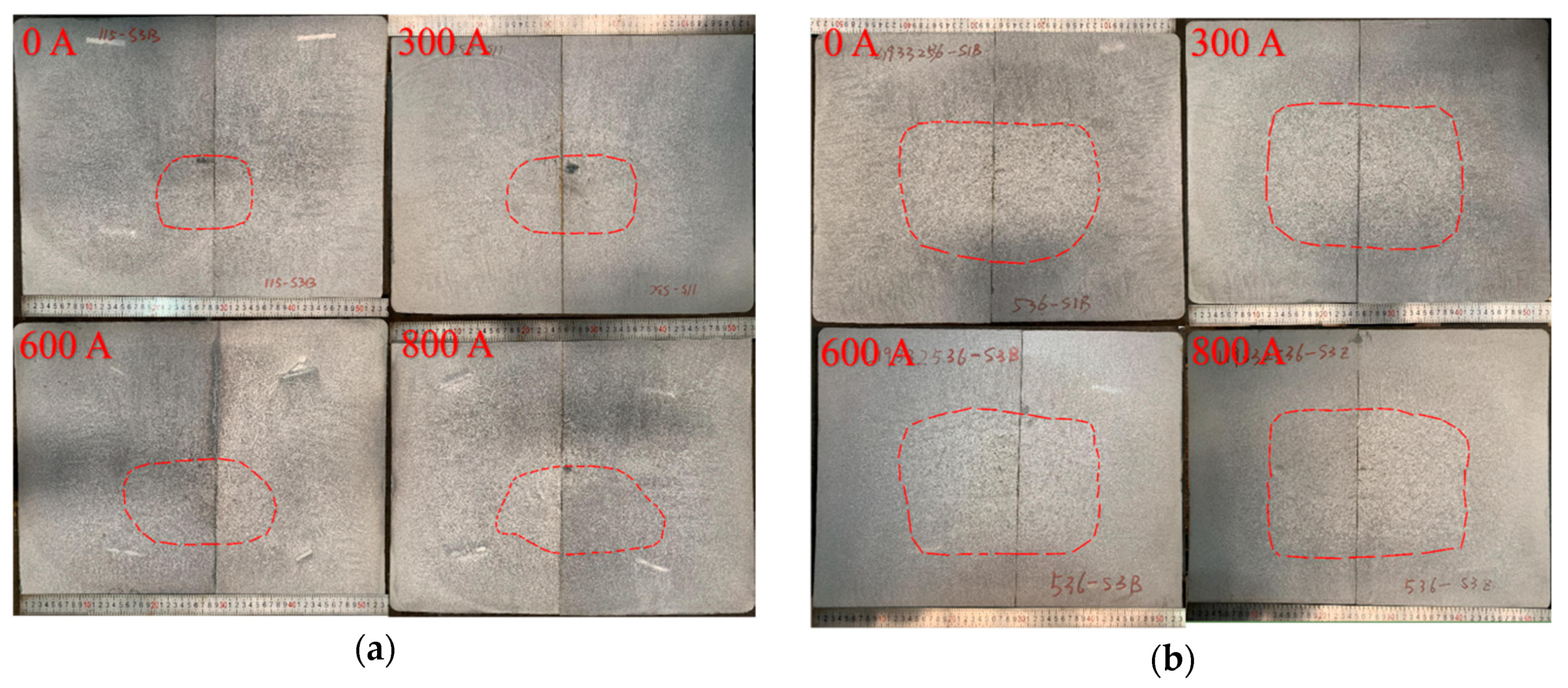
Cross-sectional macroscopic images with different stirring current intensities and the two nozzle injection modes are given in Figure 10a,b. It is clear that the central shrinkage cavity defect of the strand is severe under the single-port nozzle injection mode, but much improved with the five-port nozzle injection mode. The red dashed line signifies the front of the columnar crystal. Figure 11 shows the equiaxed crystal ratio in the two injection modes, respectively. When the current intensity is increased from 0 A to 800 A, the equiaxed crystal ratio increases from 23.1% to 27.15% for the five-port nozzle injection mode, but only increases from 6.06% to 11.71% for the single-port nozzle injection mode. In addition, the equiaxed crystal ratio increases with the current intensity for both modes, but a much larger increase has been observed for the mode with a five-port nozzle.
It has been believed that when the molten steel washes the front, it may cause the dendritic arms to melt, and the broken dendrite arms provide nucleation particles for generating equiaxed crystals [18]. The swirling flow can enhance the heat exchange between the molten steel and the initial solidified shell, promote the superheat dissipation, and lead the equiaxed crystal ratio of the strand to increase with the current intensity. In terms of the numerical simulation results given above, it can be seen that the washing velocity of the solidification front in the mold increases with the M-EMS current intensity in both injection modes. In the stirring zone, the washing velocity of the solidification front is nearly the same for the two injection modes. When the current intensity is 800 A for the single-port nozzle, the maximum washing velocity is only 0.169 m/s. For the five-port nozzle injection mode, however, the velocity reaches 0.216 m/s at the side hole jet flow zone even without M-EMS, which can slow down the growth rate of the columnar crystals. The high washing velocity can effectively break the dendrite arms to form free nuclei, which should provide an opportunity for the formation of an equiaxed crystal nucleus.
The molten steel from the side holes can directly impact the initial solidified shell in the five-port nozzle mode, resulting in extremely rapid superheat dissipation. For this reason, the temperature gradient at the solidification front is much smaller than that in the single-port nozzle injection mode. In summary, when the five-port nozzle injection mode is applied, not only do the number of nucleation particles increase, but also the supercooling of the solidification front is promoted, which ultimately leads to the equiaxed crystal ratio of the strand center being much larger than in the single-port nozzle injection mode.
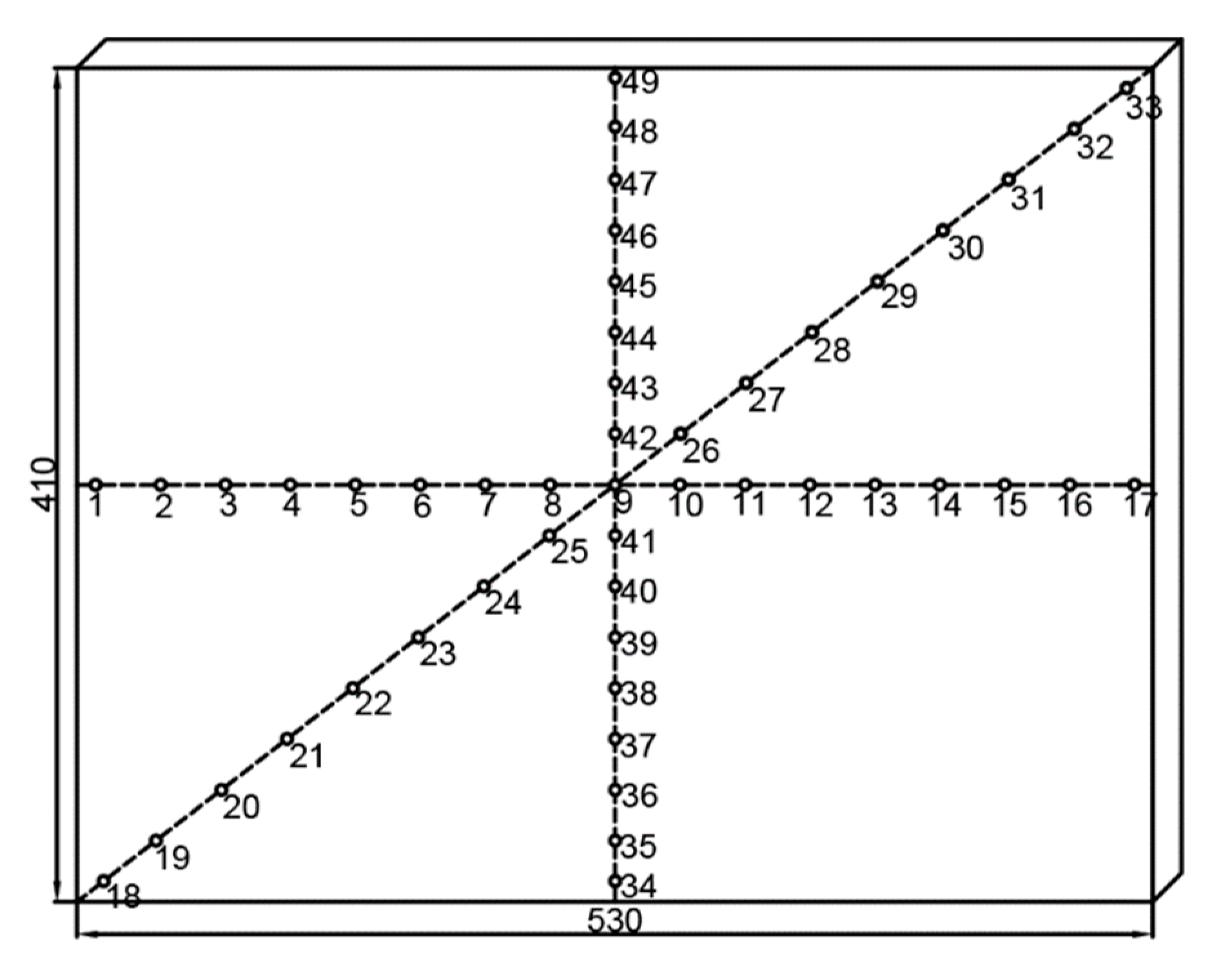
The chemistry sampling for the strand after the pickling test under the conditions of 800 A was carried out by using a 5-mm-diameter drill up to a depth of 8 mm for the two injection modes. We divided the strand into 16 parts along three directions in its cross section; a total of 49 test samples were taken, as shown in Figure 12, and the carbon content was measured by a carbon sulfur analyzer.
Figure 13 displays the segregation degree of carbon elements at the sampling point of the strand. The columnar crystals under the single-port nozzle cause serious central shrinkage and center segregation, but the carbon content distribution is uniform on the columnar crystal branches. For the five-port nozzle injection mode, however, there is a much larger equiaxed crystal ratio, together with improved central shrinkage. The enrichment of solutes at the frontier of columnar crystal growth leads to the severe centerline segregation, while the equiaxed crystal is beneficial for the distribution of the solutes, which results in a significant improvement of the central segregation. When the columnar crystal front meets the equiaxed crystal ahead, it will produce an enriched solute area called the CET zone [20]. For special steels, the factual carbon content range or the difference between the maximum and minimum values in the as-cast strand is an important index to evaluate the carbon segregation control. The carbon content range in the strand with single-port and five-port injection is 0.279% and 0.080%, respectively, which indicates that the combined application of the five-port nozzle and a current intensity of 800 A has a positive effect on the chemistry homogenization of the large bloom casting.

5. Conclusions

Plant trials and numerical simulations were conducted to investigate the combined effect of different injection modes and M-EMS on the initial transfer behavior and solidification structure evolution in a continuously cast bloom. The main conclusions are as below:
  • M-EMS can introduce a horizontal swirling flow ahead of the solidification front, promoting the superheat dissipation of molten steel and columnar to equiaxed transition (CET). When the current increases from 0 A to 800 A, the equiaxed crystal ratio in the single-port nozzle and five-port nozzle injection modes increases from 6.06% and 23.1% to 11.71% and 27.15%, respectively.
  • It is found that the flow velocity of the molten steel in front of the solidification interface for the five-port nozzle is higher than that for the single-port nozzle regardless of the M-EMS power. The washing effect here reinforces both the heat exchange through the solidification interface and the dendrite re-melting or fragmenting, stimulating the formation of equiaxed crystal in the bloom center.
  • The carbon content range is reduced from 0.279% in the single-port nozzle to 0.080% for the five-port nozzle injection mode. The central shrinkage is obviously improved for the five-port nozzle injection mode, which means the combination of a five-port nozzle and M-EMS is an important and effective way to control the as-cast macrostructure and internal quality of carbon 45 steel blooms.

Author Contributions

Conceptualization, P.W., Z.-b.Y. and J.-q.Z.; methodology, P.W.; software, P.W. and S.-x.L.; validation, P.W., Z.Z. and Z.-p.T.; investigation, P.W. and P.L.; resources, Z.-b.Y., P.W. and J.-q.Z.; writing—original draft preparation, P.W. and Z.Z.; writing—review and editing, P.W., P.L. and J.-q.Z.; visualization, P.W. and M.Q.; supervision, Z.-b.Y. and J.-q.Z.

Funding

This research was funded by the National Natural Science Foundation of China (Grant Number U1860111).

Acknowledgments

We are grateful to Zhen Lu from Sinosteel Corporation for his technical support.

Conflicts of Interest

The authors declare no conflict of interest.

References

  1. He, M.; Wang, N. Physical and Numerical Simulation of the Fluid Flow and Temperature Distribution in Bloom Continuous Casting Mold. Steel Res. Int. 2017, 88, 1600447. [Google Scholar] [CrossRef]
  2. Spitzer, K.H.; Dubke, M. Rotational electromagnetic stirring in continuous casting of round strands. Metall. Mater. Trans. B 1986, 17, 119. [Google Scholar] [CrossRef]
  3. Geng, X.; Li, X. Optimisation of electromagnetic field and flow field in round billet continuous casting mould with electromagnetic stirring. Ironmak. Steelmak. 2015, 42, 675–682. [Google Scholar] [CrossRef]
  4. Ayata, K.; Mori, H. Low superheat teeming with electromagnetic stirring. ISIJ Int. 1995, 35, 680–685. [Google Scholar] [CrossRef]
  5. Yokoya, S.; Takagi, S. Swirling flow effect in off-center immersion nozzle on bulk flow in billet continuous casting mold. ISIJ Int. 2001, 41, 1215–1220. [Google Scholar] [CrossRef]
  6. Sun, H.; Zhang, J. Effect of feeding modes of molten steel on the mould metallurgical behavior for round bloom casting. ISIJ Int. 2011, 51, 1657–1663. [Google Scholar] [CrossRef]
  7. Wang, B.X. Coupled numerical simulation on electromagnetic field and flow field in the round billet mould with electromagnetic stirring. Ironmak. Steelmak. 2015, 42, 63–69. [Google Scholar] [CrossRef]
  8. Yu, H.Q.; Zhu, M.Y. Influence of electromagnetic stirring on transport phenomena in round billet continuous casting mould and macrostructure of high carbon steel billet. Ironmak. Steelmak. 2012, 39, 574–584. [Google Scholar] [CrossRef]
  9. Li, S.; Zhang, J. Numerical Simulation of Turbulence Flow and Solidification in a Bloom Continuous Casting Mould with Electromagnetic Stirring. In TMS Annual Meeting & Exhibition, the International Symposium on CFD Modeling and Simulation in Materials Processing; Springer: Cham, Switzerland, 2018; pp. 223–236. [Google Scholar]
  10. Li, S.; Zhang, J. Study on the Electromagnetic Field, Fluid Flow, and Solidification in a Bloom Continuous Casting Mold by Numerical Simulation. Steel Res. Int. 2018, 89, 1800071. [Google Scholar] [CrossRef]
  11. Sun, H.; Zhang, J. Study on the macrosegregation behavior for the bloom continuous casting: Model development and validation. Mater. Trans. B 2014, 45, 1133–1149. [Google Scholar] [CrossRef]
  12. Li, S.; Zhang, J. Analysis on Electromagnetic Field of Continuous Casting Mold Including a New Integral Method for Calculating Electromagnetic Torque. Metals 2019, 9, 946. [Google Scholar] [CrossRef]
  13. Jones, W.P.; Launder, B.E. The calculation of low-Reynolds-number phenomena with a two-equation model of turbulence. INT J. Heat Mass Transf. 1973, 16, 1119–1130. [Google Scholar] [CrossRef]
  14. Hrenya, C.M.; Bolio, E.J. Comparison of low Reynolds number k − ε turbulence models in predicting fully developed pipe flow. Chem. Eng. Sci. 1995, 50, 1923–1941. [Google Scholar] [CrossRef]
  15. Lai, K.Y.M.; Salcudean, M. Mathematical modeling of flows in large tundish systems in steelmaking. Mater. Trans. B 1986, 17, 449–459. [Google Scholar] [CrossRef]
  16. Trindade, L.B.; Vilela, A.C.F. Numerical model of electromagnetic stirring for continuous casting billets. IEEE Trans Magn. 2002, 38, 3658–3660. [Google Scholar] [CrossRef]
  17. Thomas, B.G. Review on modeling and simulation of continuous casting. Steel Res. Int. 2018, 89, 1700312. [Google Scholar] [CrossRef]
  18. Xu, Z.G.; Wang, X.H. Investigation on formation of equiaxed zone in low carbon steel strands. Metall. Res. Technol. 2016, 113, 106–116. [Google Scholar] [CrossRef]
  19. Aboutalebi, M.R.; Hasan, M. Coupled turbulent flow, heat, and solute transport in continuous casting processes. Mater. Trans. B 1995, 26, 731–744. [Google Scholar] [CrossRef]
  20. Ghosh, A. Morphology and macrosegregation in continuously cast steel billets. ISIJ Int. 1994, 34, 338–345. [Google Scholar] [CrossRef]
Figure 1. Schematic diagrams of (a) single-port nozzle and (b) five-port nozzle.
Metals 09 01083 g001
Figure 2. (a) Schematic diagram of M-EMS; (b) location of M-EMS, (Unit, mm).
Metals 09 01083 g002
Figure 3. Comparison of the calculated and measured values for magnetic flux density.
Metals 09 01083 g003
Figure 4. Distribution of magnetic flux density under different current intensities: (a) along the strand central axis; (b) in the stirrer center.
Metals 09 01083 g004
Figure 5. Temperature contour and flow streamline on wide symmetry plane: (a) single-port nozzle; (b) five-port nozzle.
Metals 09 01083 g005
Figure 6. Maximum washing velocity at solidification front: (a) Z = 130 mm; (b) Z = 300 mm; (c) Z = 480 mm; (d) Z = 635 mm.
Metals 09 01083 g006
Figure 7. Shell thickness along the casting direction: (a) Y = 0 mm plane in single-port nozzle; (b) Y = 205 mm plane in five-port nozzle.
Metals 09 01083 g007
Figure 8. Temperature distribution of molten steel on the strand centerline along the casting direction: (a) single-port nozzle; (b) five-port nozzle.
Metals 09 01083 g008
Figure 9. Temperature distribution along the X direction of the mold exit (Z = 635 mm).
Metals 09 01083 g009
Figure 10. Macroscopic structure of the as-cast bloom cross sections under different combinations of nozzles and M-EMS currents: (a) single-port nozzle; (b) five-port nozzle.
Metals 09 01083 g010
Figure 11. Comparison of equiaxed crystal ratio of bloom strands.
Metals 09 01083 g011
Figure 12. Section sampling illustration for carbon segregation determination.
Metals 09 01083 g012
Figure 13. Segregation profiles of C along the cross section of bloom castings of carbon 45 steel: (a) left to right direction; (b) diagonal direction; (c) from the inner side to the outer side.
Metals 09 01083 g013
Table 1. Steel composition for the casting experiments (Unit, wt %).
CSiMnPSCrNi
0.42–0.500.17–0.370.5–0.8≤0.035≤0.035≤0.25≤0.25
Table 2. Geometric and thermal–physical parameters used in the current study.
ParameterValueParameterValue
Sectional dimension (mm2)410 × 530Thermal conductivity of molten steel (W·m−1·K−1)29
Inlet diameter, outer diameter of nozzle (mm)40, 90Density of molten steel (kg·m−3)7020
Immersion depth of straight nozzle (mm)100Viscosity of molten steel (kg·m−1·s−1)0.0055
Immersion depth of five-port nozzle (mm)110Liquidus temperature of molten steel (K)1763
Side holes’ size (mm2)23 × 36Solidus temperature of molten steel (K)1705
Bottom holes’ diameter (mm)12Specific heat of molten steel (J·kg−1·K−1)750
Mold working length (mm)635Latent heat of molten steel (J·kg−1)270,000
Casting speed (m·min−1)0.38Superheat of straight nozzle, five-port nozzle (K)20, 33
Relative permeability of various materials1Electrical conductivity of molten steel (S·m−1)7.14 × 10⁵
Copper mold conductivity (298 K) [16] (S·m−1)4.7 × 10⁷Copper mold conductivity (423 K) [16] (S·m−1)3.18 × 10⁷