Article

Effects of Alloying Elements on the Stacking Fault Energies of Ni58Cr32Fe10 Alloys: A First-Principle Study

1
College of Materials Science and Engineering, Sichuan University of Science and Engineering, Zigong 643000, China
2
Atlantic China Welding Consumables, Inc., Zigong 643000, China
*
Author to whom correspondence should be addressed.
Metals 2019, 9(11), 1163; https://doi.org/10.3390/met9111163
Submission received: 26 September 2019 / Revised: 21 October 2019 / Accepted: 23 October 2019 / Published: 29 October 2019

Abstract

:
Ni58Cr32Fe10-based alloys, such as Alloy 690 and filler metal 52 (FM-52), suffer from ductility dip cracking (DDC). It is reported that decreasing the stacking fault energy (SFE) of these materials could improve the DDC resistance of Alloy 690. In this work, the effects of alloying elements on the stacking fault energies (SFEs) of Ni58Cr32Fe10 alloys were studied using first-principle calculations. In our simulations, 2 at.% of Ni is replaced by alloy element X (X=Al, Co, Cu, Hf, Mn, Nb, Ta, Ti, V, and W). At a finite temperature, the SFEs were divided into the magnetic entropy (SFEmag) and 0 K (SFE0) contributions. Potentially, the calculated results could be used in the design of high-performance Ni58Cr32Fe10-based alloys or filler materials.

1. Introduction

Ni–Cr–Fe alloys have excellent mechanical and anti-corrosion properties. Thus, they are extensively used in the aerospace, power generation, and transportation industries. Nuclear energy plays a critical role in modern society because fossil fuels (like coal, oil, and gas) might run out shortly. Nuclear reactors’ construction materials should have excellent anti–corrosion properties to the intergranular stress corrosion cracking (IGSCC). In the 1950s, Ni-based Alloy 600 was developed to replace 304 stainless steels in nuclear reactor constructions. Then, researchers found that Alloy 690 has even better resistance to IGSCC [1,2,3,4,5,6].
Filler metal 52 (FM-52), having excellent resistance to stress corrosion cracking at moderate temperatures, is widely used for joining Alloy 690. However, FM-52 is susceptible to ductility dip cracking (DDC) at temperatures ranging from about 0.5 to 0.7 melting temperature. Researchers have found that the addition of alloying element Nb can improve the DDC resistance of FM-52 [1,6,7,8,9,10]. It is commonly known the following reasons could associate with DDC in the Alloy 690 weld joints: grain size, grain boundary migration, grain boundary segregation, precipitation behavior, chemical composition, and so forth [1,2,3,4,5,6]. Recent studies revealed that DDC resistance of Alloy 690 weld joints could be improved by tailoring the stacking fault energy (SFE) [11,12,13,14].
Fundamentally, DDC is a solid-state intergranular hot cracking phenomenon caused by local exhaustion of ductility at stress concentration area. A more homogeneous deformation process (or a more homogeneous distribution of dislocations) is required to achieve a better DDC resistance. Stacking fault energy (SFE) is an essential physical parameter for alloys because it intimately relates to the behavior of dislocations. In face-centered cubic (fcc) alloys, a full dislocation could dissociate into two partial dislocations separated by an intrinsic stacking fault. The dissociated dislocation cannot climb or cross-slip until a recombination process is fulfilled. Generally, a lower stacking fault energy (SFE) value leads to a broader stacking fault. As a consequence, the recombination process in low SFE materials is harder than that in high SFE materials. This condition leads to a more homogeneous distribution of dislocations and facilitates more homogeneous deformed microstructures compared with high SFE materials [11,12,13,14]. It should be pointed out that decreasing the SFE may not increase the global ductility (or macro ductility), but could potentially lead to a more homogeneous distribution of dislocations.
To get a better understanding of the dislocation behavior in Ni58–Cr32–Fe10-based alloys, the SFEs should be characterized in a wide group of alloying elements. Experimental measurements of SFE require delicate techniques. Moreover, the experimental values of SFEs might be influenced by residual stress, which arises from the sample preparation process [15]. Fortunately, first-principle studies based on density functional theory (DFT) have been considered as effective computational methods to calculate the SFE. Available calculated results are limited to Ni-continuing binary alloys [16,17,18], ternary alloys [17], and austenitic stainless steels [19,20,21].
In this work, the effects of alloying elements on the stacking fault energies (SFEs) of Ni60.5Cr29.6Fe9.9 (wt.%) or Ni58Cr32Fe10 (at. %) are studied using first-principle simulations. The selected composition is similar to Alloy 690 and FM-52. Here and throughout this paper, the compositions are expressed in at.%. In the simulations, 2 at.% of Ni is replaced by alloy element X (X=Al, Co, Cu, Hf, Mn, Nb, Ta, Ti, V, and W). Potentially, the simulated results could be used in the design of Ni58Cr32Fe10-based high-performance alloys or filler materials.

2. Computational Details

The SFEs were calculated by the axial next-nearest neighbor Ising model (ANNNI) and derived as follows [21,22,23]:
S F E = ( E hcp + 2 E dhcp 3 E fcc ) / A 2 D ,
where Ehcp, Edhcp, and Efcc are the energies of hexagonal close-packed (hcp), double hexagonal close-packed (dhcp), and face-centered cubic (fcc) structures, respectively. A2D is the area of the stacking fault. At finite temperature, the SFE in the Ni–Fe–Cr alloys could be roughly divided into the magnetic entropy (SFEmag) and 0 K (SFE0) contributions [20,21], as the contributions of electronic entropy and phonon were demonstrated to be relatively small [24]. SFEmag is derived as follows:
S F E mag = T ( S hcp mag + 2 S dhcp mag 3 S fcc mag ) / A 2 D ,
where Smag is derived as follows [25]:
S mag = i k B c i log ( μ i + 1 ) ,
where kB is the Boltzmann constant, ci is the concentration of atom i, and μi is the local magnetic moments of atom i. Previous studies demonstrated that the thermal lattice expansion is the main parameter influencing the temperature dependence of SFE [24,26]. In present work, SFEs0 were calculated at 0 K using the equilibrium volume obtained from energy-volume calculations, and SFEsmag under finite temperatures were calculated with thermal-expanded cells. The thermal expansion coefficient was adopted from the data of Alloy 690 [27].
The energies of Ni58Cr32Fe10-based random alloys were calculated with the exact muffin-tin orbitals (EMTO) [28,29]. Together with the coherent potential approximation (CPA) [30,31], the EMTO–CPA method properly describes the chemical and magnetic disorder systems [21,29]. The k-mesh for dhcp, hcp, and fcc structures was carefully tested and set as 17 × 25 × 7, 17 × 25 × 13, and 17 × 17 × 17, respectively. During the self-consistent calculations, frozen core approximation, disordered local magnetic moment (DLM) [32], and the local density approximation (LDA) [33] were adopted. It should be noted that the critical temperature for alloy 690 is 370 K [34]. Considering that DDC is a high temperature phenomenon, it is reasonable to discuss the SFEs within the DLM scheme. The total energy is converged within 10−7 Ry per atom. Then, the total energy was evaluated with the full charge density technique (FCD) approach [35]. In the FCD calculation, the exchange-correlation interactions were described by the generalized gradient approximation (GGA) in the Perdew–Burke–Ernzerhof (PBE) form [36]. This combination of approximations has been successfully used to calculate the elastic properties and SFE of Fe–Cr–Ni alloys [20,21,37]. The equilibrium unit cell volume (V), bulk modulus (B), shear modulus (G), and stacking fault energies (SFEs) of Ni and Ni58Cr32Fe10 are listed in Table 1. The calculated SFEs and equilibrium unit cell volumes (V) of Ni56Cr32Fe10X2 are listed in Table 2.

3. Results and Discussions

3.1. The Elastic Properties and SFEs of Ni and Ni58Cr32Fe10

To evaluate the reliability of our simulations, let us compare the simulated equilibrium unit cell volumes, elastic constants, and SFEs of Ni and Ni58Cr32Fe10 with the available data. The calculated equilibrium unit cell volume (V), bulk modulus (B), shear modulus (G), and SFE of Ni are 10.97 10−10m3, 198.4 GPa, 102.7 GPa, and 140.9 mJm−2, respectively. These values coincide well with the previous experimental and simulation values [17,38,39,40], as listed in Table 1.
The calculated values of equilibrium unit cell volume (V), bulk modulus (B), shear modulus (G), and SFE of Ni58Cr32Fe10 are 11.59 10−10m3, 180.1 GPa, 82.1 GPa, and 20.5 mJm−2, respectively. A detailed simulation process of the elastic constants can be found in previous work [37]. The calculated values of shear modulus (G) and equilibrium cell volume (V) coincide well with the experimental results tested from alloy with a similar composition. The calculated SFE at 0 and 298 K is 20.5 and 21.2 mJm−2, respectively (the influence of magnetic entropy on the SFEs will be discussed in Section 3.3). The difference between the calculated SFE and experimental SFE (61.0 mJm−2) published by Jimy et al. is obvious [13]. It should be noted that Jimy et al. reported that the addition of 0.56 at.% Ti reduces the SFE from 61.0 to 20.8 mJm−2. The reduction scale is ~40 mJm−2. Zhang et al. simulated the SFE of Ni-based binary alloy. They reported that the addition of 1.4 at.% Ti (the solute construction on the doped plane is 8.3 at.%) only achieves a reduction of ~19 mJm−2 [16]. We suggest that the SFE (61.0 mJm−2) of Alloy 690 reported by Jimy et al. might be overestimated, because the experimental values of SFE might be influenced by residual stress, which arises from the sample preparation process [15].

3.2. SFEs at 0 K

As shown in Figure 1a, the SFE0 for Ni58Cr32Fe10 is 20.5 mJm−2. The addition of Mn and W leaves the SFE0 almost unchanged. Al and Cu increase the SFE0 at scales of 1.4 and 1.3 mJm−2, respectively. All other elements decrease the SFE and these elements can be ordered in terms of SFE decreasing scales: Hf (9.0 mJm−2) > Ta (5.2 mJm−2) > Mo (2 mJm−2) = Nb (2 mJm−2) > Co (1.9 mJm−2) > Ti (1.6 mJm−2) > V (0.9 mJm−2).
Previously, Shang et al. simulated the SFEs of Ni-based binary alloy using supercells Ni71X [16]. Shang et al. suggested that the SFEs of Ni71X decrease about linearly with an increasing equilibrium volume of Ni71X. As shown in Figure 1b, the addition of Hf causes the most significant increase in equilibrium volume and the most apparent decrease in SFE. However, the addition of Co decreases the equilibrium volume and SFE simultaneously, and the addition of Al and Cu increase the equilibrium volume and SFE simultaneously. Thus, we suggest that, in Ni56Cr32Fe10X2, the alloying effects on the SFEs are determined not only by the equilibrium volume, but also by the interaction between electrons. There is another discrepancy between Ni-based binary alloys and Ni56Cr32Fe10X2. Shang et al. reported that all alloying elements (Al, Co, Cr, Cu, Fe, Hf, Ir, Mn, Mo, Nb, Os, Pd, Pt, Re, Rh, Ru, Sc, Si, Ta, Tc, Ti, V, W, Y, Zn, and Zr) considered in their work decrease the SFE of Ni. However, our results reveal that Al and Cu increase the SFE of Ni56Cr32Fe10X2. Lu et al. demonstrated that the alloying effects on SFE are associated with the initial composition of the matrix [20].

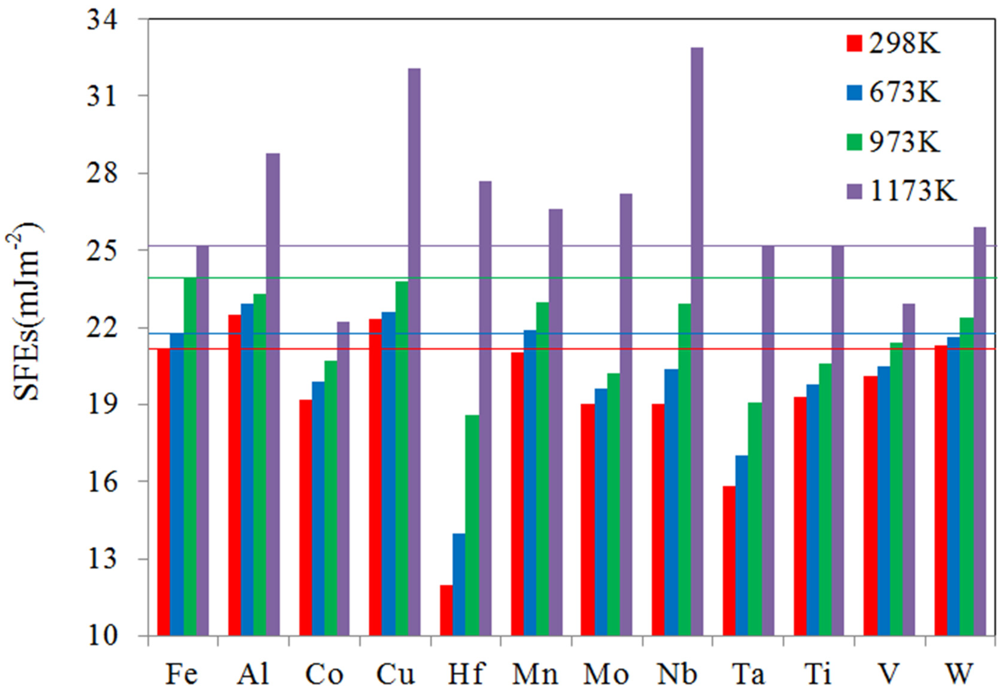
3.3. SFEs at Finite Temperature

At a finite temperature, the SFE in the Ni–Fe–Cr alloys could be roughly divided into the magnetic entropy (SFEmag) and 0 K (SFE0) contributions [20,21]. The thermal lattice expansion has been demonstrated as the main reason influencing the temperature dependence of SFEmag. It has been demonstrated that the contributions of electronic entropy and phonon were demonstrated to be relatively small. Although electronic entropy and phonon do influence the SFEs, the computational errors can be cancelled to some extent owing to the same group of cells being used [24]. For all of the systems considered in this study, we recalculated the SFE0 with thermal expanded cells. The influence of thermal expansion on the SFE0 is very small (for all of the systems, the influence is smaller than 0.3 mJm−2). Although thermal expansions do increase the energy of cells, the energy difference between fcc, hcp, and dhcp structures remained almost unchanged. Thus, only the SFEs0 at 0 K are listed in Table 2 and used in the following discussions. On the basis of Equation (2), one can deduce that the SFEmag is larger in alloys where the local magnetic moments from the fcc (μfcc), hcp (μhcp), and dhcp (μdhcp) structures exhibit a significant difference.
In Ni58Cr32Fe10 alloy, the local magnetic moments mainly develop on the Fe atom at 298 K. As listed in Table 3, the local magnetic moments (on the Fe atom) in the fcc, hcp, and dhcp structures are 2.04, 1.94, and 2.01 μB, respectively. The difference of these magnetic moments is so insignificant that the SFEmag is very small, only 0.7 mJm−2. Meanwhile, Vitos et al. reported that the local magnetic moments (on the Fe atom) in the fcc and hcp structures are 1.62 and 0.0 μB, respectively. This significant difference results in a considerable value of SFEmag (36.2 mJm−2) in their study.
In Figure 2, the SFEs (sum of chemical and magnetic contributions) at 298 K are exhibited with red rectangles, and the SFE value of Ni58Cr32Fe10 is marked out with a red line. At 298 K, the SFEsmag are so small (<1 mJm−2) in all of the alloys considered in this paper that the SFEs exhibit almost the same trend as the SFEs0. The addition of Mn and W leaves the SFE almost unchanged, while the addition of Al and Cu increases the SFE at scales of 1.3 and 1.1 mJm−2, respectively. All other elements decrease the SFE and these elements can be ordered in terms of SFE decreasing scales: Hf (9.2mJm−2) > Ta (5.4 mJm−2) > Mo (2.2 mJm−2) = Nb (2.2 mJm−2) > Co (2 mJm−2) > Ti > (1.9 mJm−2) > V (1.1mJm−2). Experiments at room temperature demonstrated that Hf, Mo, Nb, Ti, and V could decrease the SFEs of Alloy 690 [13].
The SFEs at 673 K are exhibited with blue rectangles and the SFE value of Ni58Cr32Fe10 is marked out with a blue line, in Figure 2. The addition of Mn and W leaves the SFE almost unchanged, while the addition of Al and Cu increases the SFE at scales of 1.0 and 0.6 mJm−2, respectively. Other elements can be ordered in terms of SFE decreasing scales: Hf (7.8 mJm−2) > Ta (4.8mJm−2) > Mo (2.2 mJm−2) > Ti (2.0 mJm−2) > Co (1.9 mJm−2) > Nb (1.4 mJm−2) > V (1.3 mJm−2).
The SFEs at 973 K are exhibited with green rectangles and the SFE value of Ni58Cr32Fe10 is marked out with a green line, in Figure 2. All of the elements considered in this paper decrease the SFE and these elements can be ordered in terms of SFE decreasing scales: Hf (5.3 mJm−2) > Ta (4.8 mJm−2) > Mo (3.7 mJm−2) > Ti (3.3 mJm−2) > Co (3.2 mJm−2) > V (2.5 mJm−2) > W (1.5 mJm−2) > Nb (1.0 mJm−2) > Mn (0.9 mJm−2) > Al (0.6 mJm−2) > Cu (0.1 mJm−2).
The SFEs at 1173 K are exhibited with purple rectangles and the SFE value of Ni58Cr32Fe10 is marked out with a purple line, in Figure 2. The addition of Ta and Ti leaves the SFE unchanged, while the addition of Co and V decreases the SFE at scales of 3.0 and 2.3 mJm−2, respectively. Other elements can be ordered in terms of SFE increasing scales: Nb (7.7 mJm−2) > Cu (6.9 mJm−2) > Al (3.6 mJm−2) > Hf (2.5 mJm−2) > Mo (2.0 mJm−2) > Mn (1.4 mJm−2) > W (0.7 mJm−2).
In Figure 3, Ni56Cr32Fe10Hf2 was chosen as an example, as the addition of Hf causes the most significant SFE reduction in the temperature range from 0 to 973 K, but causes a significant SFE increase at 1173 K. Previous study on austenitic stainless steels revealed that SFEmag exhibits a linear feature in the temperature range from 0 to 400 K [20]. Our results show that, in Ni58Cr32Fe10, SFEmag exhibits an almost linear feature in the temperature range from 0 to 1173 K, as shown in Figure 3a. However, SFEmag in Ni56Cr32Fe10Hf2 only exhibits a linear feature in the temperature range from 0 to 673 K. Considering that SFEmag is a local magnetic moment-related parameter, we plotted the local magnetic moments of Ni58Cr32Fe10 and Ni56Cr32Fe10Hf2, as shown in Figure 3b.
In Ni58Cr32Fe10, the local magnetic moments mainly develop on the Fe atom in the temperature range from 0 to 1173 K. However, in Ni56Cr32Fe10Hf2, the local magnetic moments also develop on the Cr atom in the temperature range from 673 to 1173 K. We suggest that the nonlinear feature of SFEmag could be caused by local magnetic moments on Cr atoms. It should be noted that DLM adopts a static picture, meaning that no thermal spin fluctuations are taken into account. However, it is suggested that the computational errors could be cancelled to some extent owing to the same group of cells being used.
During a deformation process, low SFE materials could achieve a more homogeneous distribution of dislocations and facilitate more homogeneous deformed microstructures compared with high SFE materials. The homogeneous deformation process means better DDC resistance [11,12,13,14]. On the basis of our simulation, the addition of Nb significantly decreases the SFE at room temperature. Thus, one might deduce that, at room temperature, the addition of Nb could increase the DDC resistance of Ni58Cr32Fe10-based alloys. However, room temperature experiments reveal that the improvement of DDC resistance only exists when the Nb concentration is bigger than ~1.48 at.% [6], because lower Nb concentration means more M23C6 exists in the alloy. As a consequence, micro-cracks could generate aside the M23C6, which increases the susceptibility of DDC. Besides the SFE, many other factors (such as grain size, grain boundary migration, grain boundary segregation, precipitation behavior, chemical composition, and so forth [1,2,3,4,5,6]) should be taken into account to increase the DDC resistance of Ni58Cr32Fe10-based alloys or filler materials. It should be pointed out that decreasing the SFE may not increase the global ductility (or macro ductility), but could potentially lead to a more homogeneous distribution of dislocations.

4. Conclusions

In summary, the effects of alloying elements on the stacking fault energies of Ni58Cr32Fe10 alloys were studied using first-principle calculations. In these simulations, 2 at.% of Ni is replaced by alloy element X (X = Al, Co, Cu, Hf, Mn, Nb, Ta, Ti, V, and W). At finite temperature, the SFEs were divided into the magnetic entropy (SFEmag) and 0 K (SFE0) contributions. The results reveal that only Co and V decrease the SFE in the temperature range from 0 to 1173 K. Hf, Mo, and Nb decrease the SFE in the temperature range from 0 to 973 K, but increase the SFE at 1173 K. Ta and Ti decrease the SFE in the temperature range from 0 to 973 K, but keep the SFE unchanged at 1173 K.

Author Contributions

Conceptualization, Y.D., H.L., and Y.J.; Data curation, Y.D. and X.T.; Formal analysis, Y.D. and X.T.; Funding acquisition, Y.D.; Investigation, Y.D. and Y.J.; Methodology, Y.D.; Project administration, Y.D. and H.L.; Resources, Y.D. and H.L.; Software, Y.D.; Supervision, Y.D.and H.L.; Validation, Y.D. and H.L.; Visualization, X.T.; Writing—original draft, Y.D.; Writing—review & editing, Y.D.

Funding

This research was funded by the National Natural Science Foundation of China, grant number 51701132, and Research Foundation for the introduction of talent of Sichuan University of Science and Engineering, China, grant number 2015RC57.

Conflicts of Interest

The authors declare no conflict of interest.

References

  1. Zhang, X.; Li, D.Z.; Li, Y.Y.; Lu, S.P. Effect of Nb and Mo on the Microstructure, Mechanical Properties and Ductility–Dip Cracking of Ni–Cr–Fe Weld Metals. Acta Metall. Sin. 2016, 29, 928–939. [Google Scholar] [CrossRef]
  2. Young, G.A. The Mechanism of Ductility Dip Cracking in Nickel–Chromium Alloys. Weld. J. 2008, 87, 31S–43S. [Google Scholar]
  3. Nissley, N.E.; Lippold, J.C. Ductility–Dip Cracking Susceptibility of Nickel–Based Weld Metals: Part 2: Microstructural Characterization. Weld. J. 2009, 88, 131s–140s. [Google Scholar]
  4. Wei, X.; Xu, M.; Chen, J.; Yu, C.; Chen, J.; Lu, H.; Xu, J. Fractal Analysis of Mo and Nb Effects on Grain Boundary Character and Hot Cracking Behavior for Ni–Cr–Fe Alloys. Mater. Charact. 2018, 145, 65–76. [Google Scholar] [CrossRef]
  5. Nissley, N.E.; Lippold, J.C. Ductility–Dip Cracking Susceptibility of Nickel–Based Weld Metals Part 1: Strain–to–Fracture Testing. Weld. J. 2008, 87, 257s–264s. [Google Scholar]
  6. Ahn, H.I.; Jeong, S.H.; Cho, H.H.; Lee, H.W. Ductility–Dip Cracking Susceptibility of Inconel 690 Using Nb Content. J. Alloys Compd. 2019, 783, 263–271. [Google Scholar] [CrossRef]
  7. Guo, S.; Li, D.; Pen, H.; Guo, Q.; Hu, J. Hot Deformation and Processing Maps of Inconel 690 Superalloy. J. Nucl. Mater. 2011, 410, 52–58. [Google Scholar] [CrossRef]
  8. Blaizot, J.; Chaise, T.; Nélias, D.; Perez, M.; Cazottes, S.; Chaudet, P. Constitutive Model for Nickel Alloy 690 (Inconel 690) at Various Strain Rates and Temperatures. Int. J. Plast. 2016, 80, 139–153. [Google Scholar] [CrossRef]
  9. Collins, M.G.; Ramirez, A.; Lippold, J.C. An Investigation of Ductility Dip Cracking in Nickel–Based Weld Metals—Part II. Weld. J. 2003, 82, 348S–354S. [Google Scholar]
  10. Collins, M.G.; Lippold, J.C. An Investigation of Ductility Dip Cracking in Nickel–Based Filler Materials—Part I. Weld. J. 2003, 82, 288S–295S. [Google Scholar]
  11. Unfried, J.S.; Torres, E.A.; Ramirez, A.J. In Situ Observations of Ductility–Dip Cracking Mechanism in Ni–Cr–Fe Alloys. In Hot Cracking Phenomena in Welds III; Böllinghaus, T., Lippold, J., Cross, C.E., Eds.; Springer: Berlin/Heidelberg, Germany, 2011; pp. 295–315. [Google Scholar]
  12. Unfried Silgado, J.; Ramirez, A.J. Modeling and Characterization of as–Welded Microstructure of Solid Solution Strengthened Ni–Cr–Fe Alloys Resistant to Ductility–Dip Cracking Part II: Microstructure Characterization. Met. Mater. Int. 2014, 20, 307–315. [Google Scholar] [CrossRef]
  13. Unfried–Silgado, J.; Wu, L.; Ferreira, F.F.; Garzón, C.M.; Ramírez, A.J. Stacking Fault Energy Measurements in Solid Solution Strengthened Ni–Cr–Fe Alloys Using Synchrotron Radiation. Mater. Sci. Eng. A 2012, 558, 70–75. [Google Scholar] [CrossRef]
  14. Tian, C.; Han, G.; Cui, C.; Sun, X. Effects of Stacking Fault Energy on the Creep Behaviors of Ni–Base Superalloy. Mater. Des. 2014, 64, 316–323. [Google Scholar] [CrossRef]
  15. Andric, P.; Yin, B.; Curtin, W.A. Stress–Dependence of Generalized Stacking Fault Energies. J. Mech. Phys. Solids 2019, 122, 262–279. [Google Scholar] [CrossRef]
  16. Shang, S.L.; Zacherl, C.L.; Fang, H.Z.; Wang, Y.; Du, Y.; Liu, Z.K. Effects of Alloying Element and Temperature on the Stacking Fault Energies of Dilute Ni–Base Superalloys. J. Phys. Condens. Matter 2012, 24, 505403. [Google Scholar] [CrossRef] [PubMed]
  17. Shang, S.; Wang, Y.; Du, Y.; Tschopp, M.A.; Liu, Z.K. Integrating Computational Modeling and First–Principles Calculations to Predict Stacking Fault Energy of Dilute Multicomponent Ni–Base Alloys. Comput. Mater. Sci. 2014, 91, 50–55. [Google Scholar] [CrossRef]
  18. Kumar, K.; Sankarasubramanian, R.; Waghmare, U.V. Influence of Dilute Solute Substitutions in Ni on Its Generalized Stacking Fault Energies and Ductility. Comput. Mater. Sci. 2018, 150, 424–431. [Google Scholar] [CrossRef]
  19. Lu, J.; Hultman, L.; Holmström, E.; Antonsson, K.H.; Grehk, M.; Li, W.; Vitos, L.; Golpayegani, A. Stacking Fault Energies in Austenitic Stainless Steels. Acta Mater. 2016, 111, 39–46. [Google Scholar] [CrossRef]
  20. Lu, S.; Hu, Q.M.; Johansson, B.; Vitos, L. Stacking Fault Energies of Mn, Co and Nb Alloyed Austenitic Stainless Steels. Acta Mater. 2011, 59, 5728–5734. [Google Scholar] [CrossRef]
  21. Vitos, L.; Nilsson, J.O.; Johansson, B. Alloying Effects on the Stacking Fault Energy in Austenitic Stainless Steels from First–Principles Theory. Acta Mater. 2006, 54, 3821–3826. [Google Scholar] [CrossRef]
  22. Selke, W. The Annni Model—Theoretical Analysis and Experimental Application. Phys. Rep. 1988, 170, 213–264. [Google Scholar] [CrossRef]
  23. Lu, S.; Hu, M.Q.; Delczeg–Czirjak, E.K.; Johansson, B.; Vitos, L. Determining the minimum grain size in severe plastic deformation process via first-principles calculations. Acta Mater. 2012, 60, 4506–4513. [Google Scholar] [CrossRef]
  24. Li, W.; Lu, S.; Hu, Q.; Johansson, B.; Kwon, S.K.; Grehk, M.; Johnsson, J.Y.; Vitos, L. Generalized Stacking Fault Energy of Γ–Fe. Philos. Mag. 2016, 96, 524–541. [Google Scholar] [CrossRef]
  25. Grimvall, G. Spin Disorder in Paramagnetic Fcc Iron. Phys. Rev. B 1989, 39, 12300–12301. [Google Scholar] [CrossRef] [PubMed]
  26. Ruban, A.V.; Khmelevskyi, S.; Mohn, P.; Johansson, B. Temperature–Induced Longitudinal Spin Fluctuations in Fe and Ni. Phys. Rev. B 2007, 75, 054402. [Google Scholar] [CrossRef]
  27. Kirubaharan, A.M.; Kuppusami, P.; Chakravarty, S.; Ramachandran, D.; Singh, A. Thermal Expansion and Residual Stress Behaviour of Electron Beam Evaporated Yttria Stabilized Zirconia Films on Inconel–690 Substrates. J. Alloys Compd. 2017, 722, 585–592. [Google Scholar] [CrossRef]
  28. Vitos, L. Computational Quantum Mechanics for Materials Engineers the EMTO Method and Applications; Springer: London, UK, 2007. [Google Scholar]
  29. Vitos, L. Total–Energy Method Based on the Exact Muffin–Tin Orbitals Theory. Phys. Rev. B 2001, 64, 014107. [Google Scholar] [CrossRef]
  30. Soven, P. Coherent–Potential Model of Substitutional Disordered Alloys. Phys. Rev. 1967, 156, 809–813. [Google Scholar] [CrossRef]
  31. Vitos, L.; Abrikosov, I.A.; Johansson, B. Anisotropic Lattice Distortions in Random Alloys from First–Principles Theory. Phys. Rev. Lett. 2001, 87, 156401. [Google Scholar] [CrossRef]
  32. Gyorffy, B.L.; Pindor, A.J.; Staunton, J.; Stocks, G.M.; Winter, H. A First–Principles Theory of Ferromagnetic Phase Transitions in Metals. J. Phys. F Met. Phys. 1985, 15, 1337. [Google Scholar] [CrossRef]
  33. Ceperley, D.M.; Alder, B.J. Ground State of the Electron Gas by a Stochastic Method. Phys. Rev. Lett. 1980, 45, 566–569. [Google Scholar] [CrossRef] [Green Version]
  34. Lemire, R.J.; McRae, G.A. The corrosion of Alloy 690 in high-temperature aqueous media—Thermodynamic considerations. J. Nucl. Mater. 2001, 294, 141–147. [Google Scholar] [CrossRef]
  35. Vitos, L.; Kollár, J.; Skriver, H.L. Full charge-density scheme with a kinetic-energy correction: Application to ground-state properties of the 4d metals. Phys. Rev. B 1997, 55, 13521–13527. [Google Scholar] [CrossRef] [Green Version]
  36. Perdew, J.P.; Burke, K.; Ernzerhof, M. Generalized Gradient Approximation Made Simple. Phys. Rev. Lett. 1996, 77, 3865–3868. [Google Scholar] [CrossRef] [Green Version]
  37. Dou, Y.; Luo, H.; Zhang, J. Elastic Properties of Fecr20ni8xn (X = Mo, Nb, Ta, Ti, V, W and Zr) Austenitic Stainless Steels: A First Principles Study. Metals 2019, 9, 145. [Google Scholar] [CrossRef]
  38. Shang, S.L.; Kim, D.E.; Zacherl, C.L.; Wang, Y.; Du, Y.; Liu, Z.K. Effects of Alloying Elements and Temperature on the Elastic Properties of Dilute Ni–Base Superalloys from First–Principles Calculations. J. Appl. Phys. 2012, 112, 053515. [Google Scholar] [CrossRef]
  39. Simmons, G.; Wang, H. Single Crystal Elastic Constants and Calculated Aggregate Properties; Mit: Cambridge, MA, USA, 1971. [Google Scholar]
  40. Carter, C.B.; Holmes, S.M. The stacking-fault energy of nickel. Philos. Mag. A J. Theor. Exp. Appl. Phys. 1977, 35, 1161–1172. [Google Scholar] [CrossRef]
Figure 1. (a) Calculated stacking fault energies (SFEs) of Ni56Cr32Fe10X2. (b) Calculated equilibrium cell volumes (V) of Ni56Cr32Fe10X2. The values of SFE and V for Ni58Cr32Fe10 are marked out by a red line in both (a,b).
Metals 09 01163 g001
Figure 2. Finite temperature SFEs (sum of chemical and magnetic contributions) of Ni56Cr32Fe10X2 (X = Al, Co, Cu, Hf, Mn, Nb, Ta, Ti, V, and W) alloys.
Metals 09 01163 g002
Figure 3. (a) Magnetic entropy contribution of stacking fault energy (SFEsmag) of Ni58Cr32Fe10 and Ni56Cr32Fe10Hf2. (b) Local magnetic moments of atom Fe and Cr in Ni58Cr32Fe10 and Ni56Cr32Fe10Hf2.
Metals 09 01163 g003
Table 1. The equilibrium unit cell volume (V) in 10−10m3, bulk modulus (B) and shear modulus (G) in GPa, and stacking fault energies (SFEs) in mJm−2 of Ni and Ni58Cr32Fe10. Values without a superscript are calculated at 0 K.
AlloyVBGSFE
Ni10.97198.4102.7140.9
10.982 a196.5 a103.2 a131.5 b
10.95 c187.6 c101.1 c120–130 d
Ni58Cr32Fe1011.59180.182.120.5
21.2 e
Alloy 690 79.3 f
Ni59.3Cr30.7Fe1011.37 f 61.0 g
a First principle data from the literature [38]; b first principle data from the literature [17]; c experimental data from the literature [39]; d experimental data from the literature [40]; e first principle data at 293 K; f experimental data from (https://www.specialmetals.com/assets/smc/documents/alloys/inconel/inconel-alloy-690.pdf); g experimental data from the literature [13].
Table 2. Equilibrium cell volumes (V) in 10−10m3 and stacking fault energies (SFEs) in mJm−2 of Ni56Cr32Fe10X2. The SFEs are divided into the 0 K contribution (SFEs0) and the magnetic entropy contribution (SFEsmag). SFEsmag are calculated with thermal-expanded cells (at 298, 673, 973, and 1173 K).
AlloyVSFEs0SFEsmag (298 K)SFEsmag (673 K)SFEsmag (973 K)SFEsmag (1173 K)
Ni58Cr32Fe1011.60 20.5 0.71.33.44.7
Ni56Cr32Fe10Al211.66 21.9 0.61.01.46.9
Ni56Cr32Fe10Co211.59 18.6 0.61.32.13.6
Ni56Cr32Fe10Cu211.63 21.8 0.50.82.010.3
Ni56Cr32Fe10Hf211.93 11.5 0.52.57.116.2
Ni56Cr32Fe10Mn211.63 20.4 0.61.52.66.2
Ni56Cr32Fe10Mo211.76 18.5 0.51.11.78.7
Ni56Cr32Fe10Nb211.83 18.5 0.51.94.414.4
Ni56Cr32Fe10Ta211.80 15.3 0.51.73.89.9
Ni56Cr32Fe10Ti211.79 18.9 0.40.91.76.3
Ni56Cr32Fe10V211.66 19.6 0.50.91.83.3
Ni56Cr32Fe10W211.74 20.7 0.60.91.75.2
Table 3. Local magnetic moments (μB) on atom Fe and SFEmag (mJm−2) in Ni58Cr32Fe10 at 298 K.
AlloyμfccμhcpμdhcpSFEmag
Ni58Cr32Fe102.041.942.010.7
Fe70.5Cr17.5Ni12 a1.620.0036.2
a First principle data at 300 K [21].

