Article

Observations on the Relationship between Crystal Orientation and the Level of Auto-Tempering in an As-Quenched Martensitic Steel

1
Materials and Mechanical Engineering, Centre for Advanced Steels Research, University of Oulu, 90014 Oulun Yliopisto, Finland
2
Outotec Research Center, Outotec Oy, Kuparitie 10, P.O. Box 69, FI-28101 Pori, Finland
3
Kerttu Saalasti Institute, University of Oulu, Pajatie 5, FI-85500 Nivala, Finland
4
Department of Materials, University of Oxford, Parks Road, Oxford OX1 3PH, UK
*
Author to whom correspondence should be addressed.
Metals 2019, 9(12), 1255; https://doi.org/10.3390/met9121255
Submission received: 7 October 2019 / Revised: 19 November 2019 / Accepted: 21 November 2019 / Published: 24 November 2019

Abstract

:
Auto-tempering is a feature of the technologically important as-quenched low-carbon martensitic steels. The focus of this paper is on the morphology of the martensite and the orientation of the last forming untempered regions in relation to the earlier formed auto-tempered martensite in both small and large austenite grains. A low-carbon martensitic steel plate was austenitized for 24 h and quenched to room temperature. The resulting microstructure was characterized using electron microscopy and electron back scattered diffraction (EBSD) imaging. It was found that all the untempered regions in the martensitic microstructure were oriented with the plane normals {100} close to the thickness, or normal, direction of the plates. Variant analysis revealed that the untempered regions and the auto-tempered regions are part of the same packet.

1. Introduction

High-strength low-carbon martensitic steels provide low-cost environmentally efficient materials for weight critical engineering. The wider use of these materials could improve energy savings and reduce the carbon footprint of many products [1]. Low-carbon steels are commonly used as structural materials as they have good weldability. Using such steels in the quenched martensitic condition provides both good weldability and high strength making them attractive materials for structural applications [2,3].
Martensite is formed by a diffusionless transformation at low temperatures when austenitized steel is quenched [2,3]. The onset temperature is known as the martensitic start temperature (Ms). In low-carbon steels, martensite has a lath morphology [2,3,4]. The carbon atoms that are fully soluble in austenite prior to the transformation to martensite become supersaturated in the bcc matrix after the formation of martensite. As the solubility of C in ferrite in equilibrium with cementite is only 0.00022 wt.% at 400 °C, for example, there is a large driving force for the precipitation of cementite following the formation of a martensite lath. The mobility of C in ferrite at the temperatures at which martensite typically forms in low-C steels is so high that even at cooling rates of 1000 °C/s there is time for cementite to nucleate and grow in the martensite laths that form at temperatures close to the Ms temperature [5]. This phenomenon is known as auto-tempering as the resultant microstructure resembles that of tempered martensite. The auto-tempering in martensite occurs when the Ms temperature is sufficiently high, as is often the case in low-carbon steels [2,3]. When compared to steels without auto-tempering, auto-tempered steels exhibit superior toughness [6] and improved formability [7].
The lath martensite microstructure has been studied extensively. The lath structure in a prior austenite grain can be divided into packets, and these packets is subdivided into blocks and sub-blocks [2,8,9,10]. In the case of Kurdjumov–Sachs (K-S) orientation relationship between the prior austenite and the martensite, the laths can form up to 24 unique variant orientations within a single parent austenite grain [9]. Morito et al. [10] found that in low-carbon steels, blocks can further be subdivided into sub-blocks which have two K-S variants with a misorientation of about 10 degrees. The formation of martensite is dependent on the prior austenite grain size. Furuhara et al. [11] demonstrated that the packet and block sizes decrease with a reduction of the prior austenite grain size. Morito et al. [12] showed that relatively large prior austenite grains (with a mean linear intercept grain size 28 um) were divided into several packets, while small grains (2 um) were dominated by a single packet.
Celada-Casero et al. [13] showed that austenite grain refinement accelerates martensite formation during the initial stages of the transformation. Hidalgo et al. [9] showed that when the prior austenite grain size was reduced, the volume fraction of retained austenite increased. Thus, the auto-tempered carbides became refined and the carbon concentration that remained in the martensite matrix increased. It is generally assumed that the auto-tempered carbides are most prominent within the martensite that forms close to the Ms temperature. This is due to the fact that the carbon in supersaturated solution after the transformation of such regions can diffuse the greatest distance during the quench [5]. The low-temperature impact and fracture toughness of ferritic steels depends on the orientation of the {100} cleavage planes with respect to the principal stress below the impact test specimen notch or fracture toughness specimen fatigue crack. In the case of lath martensitic steels, the coherence length on {100} planes that are almost normal to the principal stress determines the cleavage crack length, which affects the toughness [14]. Therefore, a detailed study of the crystal orientations of the different parts of the martensitic structure is of interest.
The first objective of this study is to investigate the martensite morphology in both large and small grains in a low-carbon steel using scanning electron microscopy (SEM) and electron backscatter diffraction (EBSD). The second objective is to investigate the crystallographic orientation of the least auto-tempered regions relative to that of the most highly auto-tempered regions.

2. Materials and Methods

The starting material for this study was a hot-rolled 12 mm thick carbon steel plate. Specimens machined from the plate had dimensions of 20 × 10 × 10 mm. These specimens were austenitized in a Nabertherm L5P/11 furnace (Nabertherm GmbH, Lilienthal, Germany) at a temperature of 917 °C for 24 h in an inert argon gas atmosphere to give a bimodal prior austenite grains distribution. The specimens were subsequently quenched in water to obtain a fully martensitic structure. The martensitic start temperature for this steel was determined by Ramesh Babu et al. [15] as 435 °C. The chemical composition was analyzed using a Spectruma GDA 750 Analyser glow discharge optical emission spectroscope (Spectruma Analytik GmbH, Hof, Germany) after the thermal treatment. The mean chemical composition was then analyzed from the centerline and is as shown in Table 1.
Cross sections of the specimens were cut normal to the rolling direction and mounted in thermosetting hot mounts. It has been observed that hot mounting this type of steel can cause additional low temperature tempering [16]. The sample was mounted deeper into the mould so as to attempt to minimize the heating effects from the hot mounting procedure. However, some additional carbide precipitation is expected to occur as a result of the hot mounting, which was found necessary for obtaining good SEM images. After mounting and grinding, the final polishing procedure used a 40 nm colloidal silica suspension to achieve a mirror-like finish.
Crystal orientations were determined by using the EBSD technique with an Oxford Instruments EBSD detector (Oxford Instruments, Oxfordshire, Abingdon, UK) in combination with a Zeiss Ultra Plus SEM (Carl Zeiss AG, Oberkochen, Germany) operated at 15 kV, with an aperture size of 120 µm, a working distance of 10–12 mm and a minimum step size of 0.03 µm. The Aztec (Aztec version 3.0 SP1, Oxford Instruments, Oxfordshire, Abingdon, UK) and HKL (Channel5 version 5.12.56.0, Oxford Instruments, Oxfordshire, Abingdon, UK) software of Oxford instruments were used to acquire and process the EBSD patterns. Both large diameter (200 µm) and small diameter (20 µm) grains were examined. The areas to be studied were marked with Vicker’s indents made using a 5 N load with a CSM MHT-Z-AE microhardness tester (CSM Instruments SA, A company of Anton Paar, Peseux, Switzerland). Noise reduction was conducted on the EBSD maps to fill in non-indexed patterns with HKL Channel 5 Tango software (Channel 5 version 5.12.56.0, Oxford Instruments, Oxfordshire, Abingdon, UK). The standard noise reduction process used six neighboring points, which resulted in the modification of less than 10% of the indexed points.
After the EBSD patterns were produced for a particular region, the same microstructure was further studied by the SEM. However, the EBSD technique introduces surface contamination. Thus, the samples were polished again with 40 nm colloidal silica to remove this contamination and etched with 2% nital solution. SEM Inlens secondary electron (SE) images were captured using a Zeiss Sigma (Carl Zeiss AG, Oberkochen, Germany) at 5 kV with an aperture diameter of 30 µm.
Prior austenite grain sizes were determined and a crystallographic martensite orientation variant analysis was conducted with the aid of the EBSD maps processed with an austenite reconstruction algorithm [17]; these were built using the MTEX (version 5.1.1, Institute of Mathematics, TU Chemnitz, Germany) texture analysis MATLAB (version 2018b, MathWorks, Inc., Natick, MA, USA) toolbox [18]. In addition, MTEX was also used to calculate misorientation angles.

3. Results

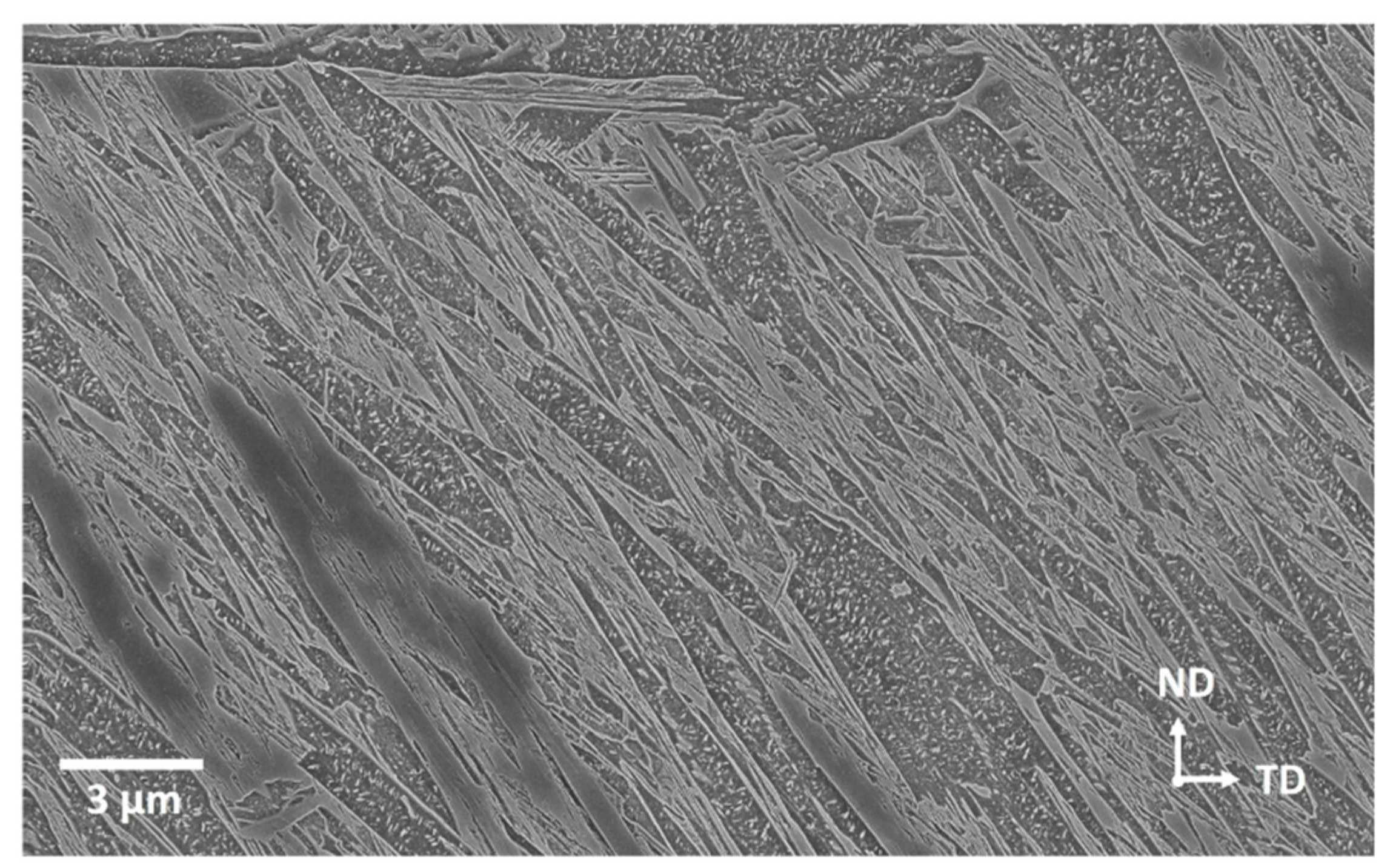
3.1. Martensite Morphology

It will be shown below that the applied heat treatment resulted in a bimodal distribution of prior austenite grain sizes comprising large grains with a diameter of ca. 300 µm and small grains with a diameter of ca. 17 µm. The grain boundary pinning effects caused by the presence of VC and AlN at the prior austenite grain boundaries has caused the abnormal distribution in the prior austenite grain sizes. Irrespective of the prior austenite grain size, the as-quenched microstructure was fully martensitic. Figure 1 shows an example of the martensite morphology in a large austenite grain. Auto-tempered carbides precipitated within the first formed martensitic regions. These carbides have previously been identified as cementite [16]. It was also observed that hot mounting effects were not very significant in the samples used for the current paper. The main distinguishing feature of the hot-mounting effects would have been the appearance of new precipitates in the regions which are free of auto-tempered cementite resolvable in the SEM [16]. This might be due to the fact that the thickness of the samples were much more than the dimensions of the samples used in Ramesh Babu et al. [16] where the effects of hot mounting were observed. However, as it was shown in Saastamoinen et al. [19], tempering did not affect the final texture therefore tempering due to hot-mounting would not have a final impact with regards to the orientations.
The morphological features in the as-quenched steel can be classified as follows:
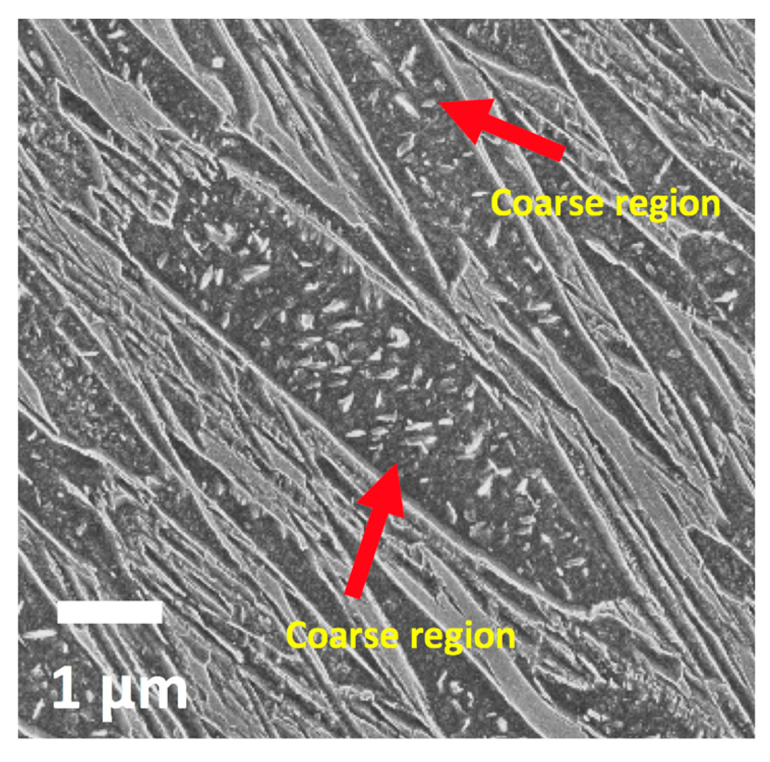
  • Coarse auto-tempered regions. The coarse regions were generally wedged shape and had a high density of auto-tempered precipitates within them, as shown in Figure 2. The coarse laths could simply be thin laths intersected by the specimen surface at a small angle. But Morsdorf et al. [20] showed that the coarse laths are clearly thicker than the surrounding thin laths using 3D sectioning techniques. As stated by Morsdorf et al. [20], the austenite matrix is soft and defect density is low just above the Ms temperature. Therefore, just below the Ms temperature, there is a low resistance to the formation of the coarse martensitic regions. The degree of auto-tempering is higher within these regions as, during quenching, they form at the highest temperatures where atomic mobility is high and beneficial for the nucleation and growth of cementite. The matrix of the coarse auto-tempered regions was the most highly etched of all the features within the microstructure, as shown by the imaged carbides in Figure 2.
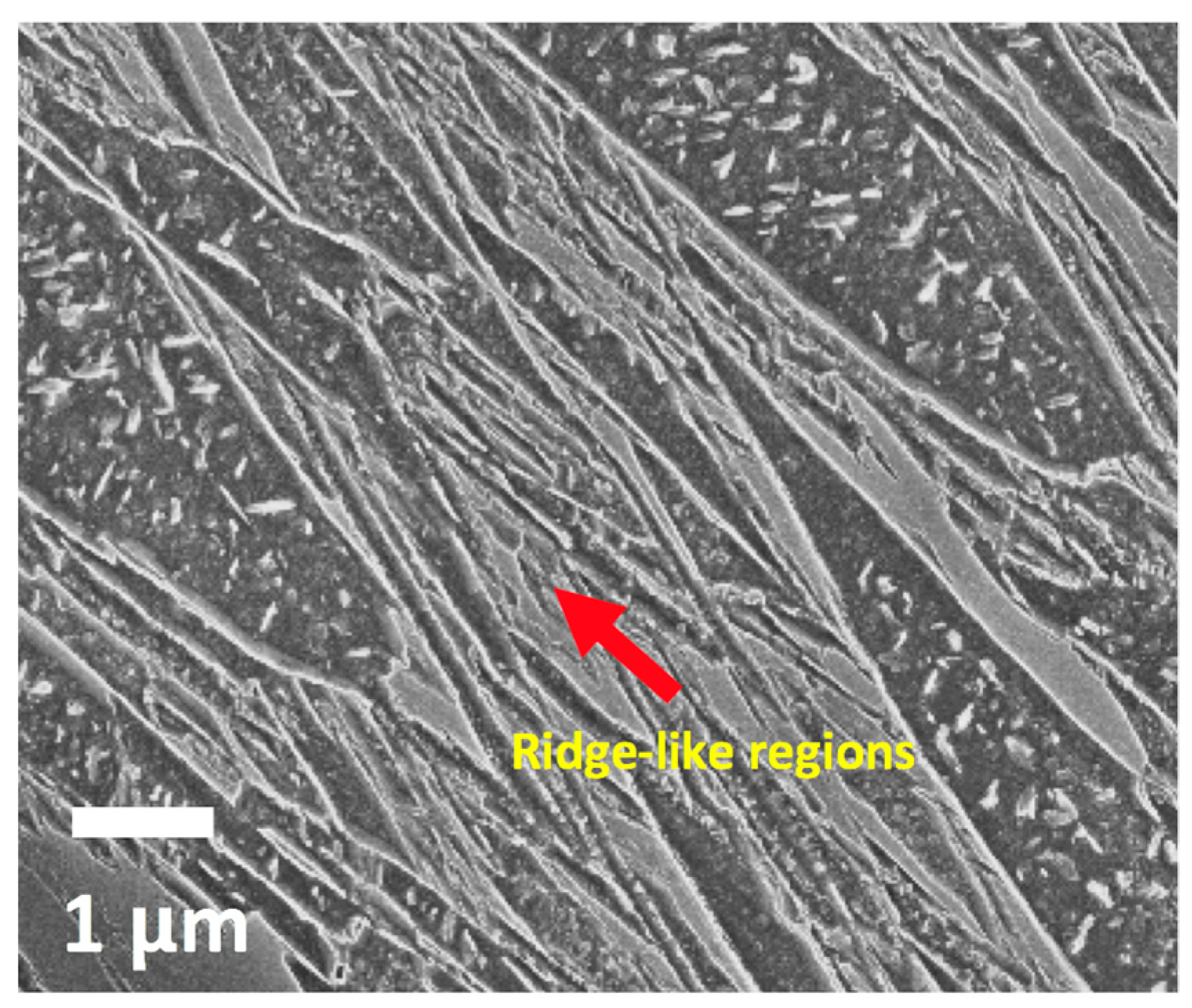
  • Ridge-like regions. These features appear as narrow raised bands, i.e., ridges, as shown in Figure 3. They tended to surround the coarse martensite features. After the formation of the coarse auto-tempered martensitic regions, the falling temperature and increasing dislocation density of the austenite resulting from the plastic accommodation of the martensite already formed leads to progressive hardening of the untransformed austenite [20]. It follows that the martensite in the ridge-like regions has had to grow into ever stronger austenite. The ridge-like regions consist of clusters of fine martensite laths, which etch to different degrees thereby creating the ridge appearance. It has been shown ferrite with a higher concentration of carbon in solid solution etches less in nital as does carbon supersaturated retained austenite at the lath boundaries [21]. Within the ridge-like regions, carbides were either absent or smaller in size than the carbides found in the coarse auto-tempered regions.
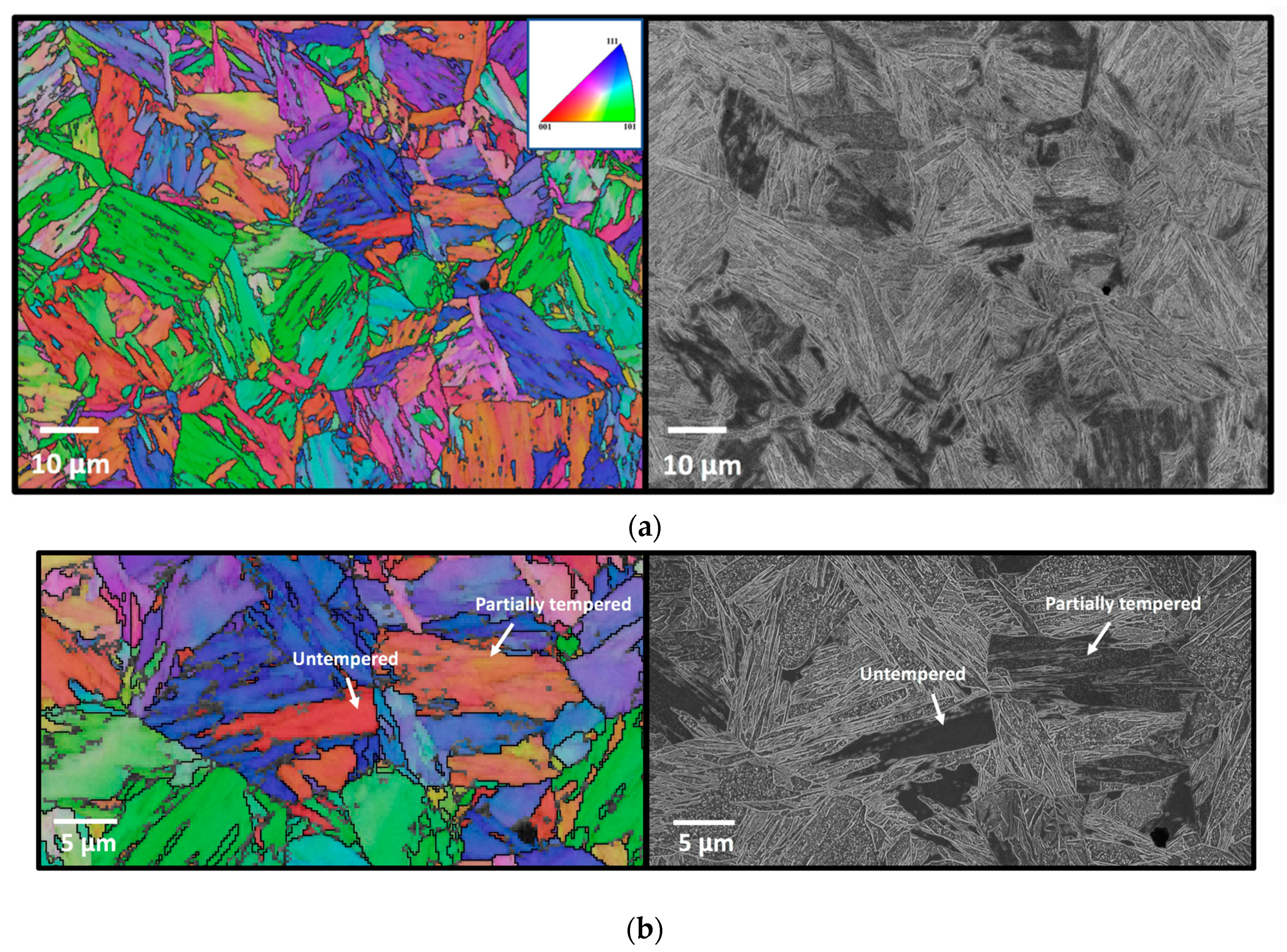
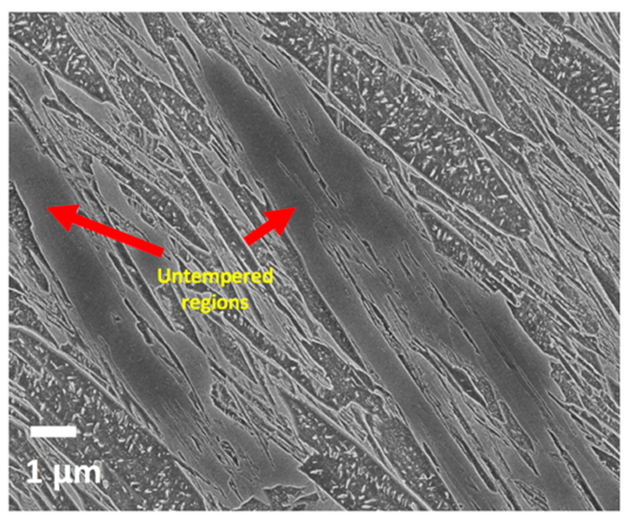
  • Untempered regions. These are unetched featureless regions that with no carbides visible were presumably the last regions to transform into martensite, see Figure 4. As the transformation of these regions takes place at low temperatures, near the martensite finish temperature, it is reasonable to postulate that they have high levels of carbon remaining in solid solution leading to very little etching in nital and the resulting plateau-like topography regions, contrasting from the ridge-like and coarse regions.

3.2. Orientations of the Martensitic Regions

The large grain in Figure 5 has an equivalent circle diameter (ECD) of 289 μm. Figure 5a,b shows EBSD inverse pole figure (IPF) maps with the colors indicating the crystallographic orientation of the plate normal direction (ND), i.e., thickness direction. Figure 5b,c are higher resolution EBSD IPF and SE images from an identical area within the large grain. It can be seen that the coarse auto-tempered regions and the ridge-like regions have colors ranging from light blue to purple, corresponding to the {111}//ND to {112}//ND orientations. However, throughout the grain all of the untempered regions with no visible carbides show a red shade indicating that they have the same orientation close to {100}//ND. In addition, it can be seen that the slightly tempered regions containing small carbides all show an orange shade which corresponds to the orientation {103}//ND. In general, the orange colored, which were slightly tempered, regions had an island shaped morphology.
The finer laths that appear as ridge-like features (Figure 3) generally form with the same orientation as the previously formed adjacent coarse auto-tempered regions. The slightly tempered martensitic regions, shaded orange corresponding to {103}//ND, have formed earlier than the red untempered regions because a higher degree of auto-tempering requires more carbon diffusion.
Figure 6 shows another region of the same sample where the grains are small [mean ECD = 16.9 μm, standard deviation = 9.4 μm]. As in the case of the large grain, it can be seen that the relatively untempered regions, i.e., the dark etching regions in the secondary electron image, have similar orientations in the IPF maps, i.e., red or red-brown shades corresponding to orientations close to {100}//ND. It is interesting that this seems to be the case in all grains, irrespective of the orientation of the neighboring ridge-like or coarse regions. In the case of the fine-grained austenite, the relatively untempered regions appeared to be islands in shape rather than elongated as was the case in the large grain. As seen in Figure 6b, the red IPF regions in the sample appeared untempered, while the red-orange regions in the IPF image were partially untempered. The green, blue and purple regions in the IPF images, corresponding to {101}//ND, {111}//ND and {112}//ND respectively, consist of a mixture of coarse auto-tempered regions and the ridge-like regions.
Reisinger et al. [22] pointed out that, when etching in Nital, surfaces parallel to the {100} planes etch more slowly than surfaces parallel to other planes. Such an effect cannot explain the lack of etching seen in the untempered regions, however, since the specimens have been sectioned perpendicular to the plate RD. The untempered regions are oriented such that the plate ND is parallel to <100> as shown by the red shade in Figure 7a, but Figure 7b the untempered regions show green shades meaning that the etched surfaces of the untempered regions are oriented close to {101}.
It was seen in Ramesh Babu et al. [16] that the hot mounting causes the appearance of carbides in the relatively untempered regions in 6 mm diameter Gleeble quenched cylindrical specimens. Whereas no precipitation visible in the SEM is seen in the untempered regions of cold mounted specimens. This indicates that the slow etching of the untempered regions is due to a supersaturation of carbon in the matrix.
Irrespective of the fact that the untempered regions may be tempered or not, it has been previously illustrated and confirmed that in lath martensitic steels, the effective grain size for cleavage fracture is the coherence length of the {100} cleavage crack planes [23]. Therefore, the EBSD results showing the untempered regions orienting close to the {100}// ND would have important consequences for the toughness of as-quenched martensitic plates.

3.3. Martensite Orientation Variants

Figure 8 and Figure 9 display the martensite variant map and corresponding variant distribution histogram for the large prior austenite grain. Figure 10 and Figure 11 display a similar map and histogram for the small grains. The numbers denote the different variants of the K-S orientation relationship following the scheme introduced by Morito et al. [10]. As described by Nyyssönen et al. [17] and Morito et al. [10], the variants were divided into groups having the same close-packed planes, i.e., V1 to V6, V7 to V12, V13 to V18 and V19 to V24. Variants within the same group form martensite packets. Morito et al. [10] showed that in low-carbon steels, the packets can further be sub-divided into blocks. Each block consists of specific combinations of sub-block pairs with a small misorientation (about 10 degrees) between them. For example, as shown by Morito et al. [10], in a packet consisting of V1–V6 lath variants, the sub-block pairs are V1/V4, V2/V5 and V3/V6.
The collected EBSD data was processed with Matlab® running the MTEX [18] crystallography toolbox. Note that while importing to MTEX, the orientations were rotated into alignment with the specimen coordinate system, following the default import settings.
Initially, the orientation map was segmented into a grain map using a 3° angular threshold, followed by the manual selection of grains corresponding to the untempered areas shown in Figure 5 and Figure 6. The relationship of these areas to their neighboring areas was further examined by the crystallographic reconstruction of the prior austenite phase. Note that the term “grain” used in this context refers strictly to the segmented orientation clusters, which are in reality composed of one or more martensitic laths. The reconstruction was carried out following the method proposed by Nyyssönen et al. [17]. The representative mean γ/α’ orientation relationship was iteratively determined from the intergranular misorientations. Table 2 shows 24 angle–axis pairs corresponding to all of the possible misorientations between martensitic variants.
The grain map was divided into clusters representing prior austenite grains via Markov Clustering [24]. The prior austenite orientation could then be calculated for each cluster, resulting in a prior austenite orientation map. Each austenite/martensite orientation pixel could then be separately indexed to Table 2, showing the 24 possible variants of martensite in the indexing scheme proposed by Morito et al. [10]. The variants are shown graphically overlaid on an EBSD band contrast map in Figure 8 and Figure 10. Each packet has been given its own color scheme to facilitate an intuitive visual identification of the packet structure.
Figure 8 shows the variant indexing for the orientation map over the part of the single large austenite grain boxed in Figure 5a. The area shown is primarily composed of two packets comprising variants V1–V6, arranged into blocks of the variant pairs V1/V4, V2/V5 and V3/V6, and variants V19–V24, arranged into blocks of the variant pairs V19/V22, V20/V23 and V21/24. Figure 8 shows a histogram of the distribution of the variants indexed in Figure 8. The variants are divided fairly evenly in the V1/V6 packet. In the V19/V24 packet, the dominant block is V19/V22. The untempered areas, outlined by white boundaries in Figure 8, belong to the dominating V1–V6 packet, while usually also sharing at least some of their outlying boundaries with another packet. The untempered areas consist nearly exclusively (appr. 87.6% of indexed orientation pixels) of the block V2/V5. This is even true of the untempered region surrounded by other packets.
Figure 10 shows the variant indexing for the region of small prior austenite grains shown in Figure 6a. A general feature of the smaller grains is a correspondingly smaller packet size. The packet/block structure is similar to that found in the large austenite grain, with a packet containing multiple blocks and the untempered areas consisting of a single block. The untempered areas consist of the blocks V1/V4, V7/V10, V8/V11, V13/V16, V14/V17 and V20/V23 depending on the grain concerned. As seen in Figure 11, the variants in packets V7–V12 and V19–V24 are evenly distributed. Blocks V1/V4 and V3/V6 are dominant in the V1–V6 packet while the blocks V13/V16 and V15/V18 are dominant in the V13–V18 packet.
The apparent variant selection in the untempered areas cannot be explained by comparison with immediate neighbors. Instead, it is necessary to consider the untempered areas as part of the larger packet structure.
Morito et al. [10] calculated the total shape strains resulting from both the transformation of a single variant as well as several different variant combinations. Their calculations showed that combinations of pairs of variants in a single packet reduced the total shape strain in all cases due to self-accommodation, while the combination of all variants in a packet reduced the total shape strain by a factor of 10. Assuming that the untempered areas in Figure 8 and Figure 10 have been the last to transform into martensite, it is possible that the selection of specific variants in the untempered regions has occurred by the principle of the minimization of transformation strains through self-accommodation.

4. Conclusions

When studied in the scanning electron microscope after nital etching, the microstructure of the studied as-quenched, fully martensitic, low-carbon steel plate divides into three distinct morphology types that form at successively lower temperatures during quenching: (1) auto-tempered regions comprising deeply etched, coarse, wedge-shaped laths and intra-lath cementite precipitates, (2) ridge-like regions comprising fine laths with most cementite precipitates below the resolution limit of the microscope, and (3) featureless, little etched untempered regions with no visible carbides.
Irrespective of grain size in the range 17–289 μm and location in the plate, the coarse auto-tempered regions and the ridge-like regions have {111}//ND to {112}//ND orientations. However, the untempered regions with no visible carbides have the same orientation of or close to {100}//ND. There were also slightly tempered regions containing small carbides. These regions correspond to an approximate orientation of {103}//ND.
Variant analysis reveals the untempered regions to be single blocks, which are generally part of the same packet as the adjacent coarse auto-tempered and ridge-like regions. The variants formed in the untempered regions are most likely selected by the principle of the minimization of transformation strains in a given packet through self-accommodation.

Author Contributions

Conceptualization, S.R.B., D.P.; methodology, S.R.B.; M.J.; software, S.R.B., M.J. and T.N.; validation, S.R.B., D.P. and T.N.; formal analysis, S.R.B., D.P. and T.N.; investigation, S.R.B., D.P.; data curation, S.R.B.; writing—original draft preparation: S.R.B.; writing—review and editing, T.N., M.J., A.J., T.P.D., S.P.; D.P.; visualization, S.R.B.; T.N.; supervision, D.P.; project administration, J.K.

Funding

The authors are grateful for financial support from the European Commission under grant number 675715-MIMESIS-H2020-MSCA-ITN-2015, which is a part of the Marie Sklodowska-Curie Innovative Training Networks European Industrial Doctorate Programme. Sakari Pallaspuro thanks the funding from the Academy of Finland (# 311934). T.P. Davis is funded by the Clarendon Scholarship from the University of Oxford and United Kingdom’s Engineering and Physical Sciences Research Council Fusion Centre for Doctorial Training [EP/L01663X/1].

Acknowledgments

The authors thank Jussi Paavola for his help with regards to the furnace treatments. The authors would also like to thank Pasi Suikkanen from SSAB Europe Oy for his support. The support of SSAB Europe Oy in providing the steel studied is acknowledged.

Conflicts of Interest

The authors declare no conflict of interest. The funders had no role in the design of the study; in the collection, analyses, or interpretation of data; in the writing of the manuscript, or in the decision to publish the results.

References

  1. Kömi, J.; Karjalainen, P.; Porter, D. Direct-Quenched Structural Steels. In Encycl. Iron, Steel, Their Alloys; CRC Press: Boca Raton, FL, USA, 2016; pp. 1109–1125. [Google Scholar]
  2. Krauss, G. Martensite in steel: Strength and structure. Mater. Sci. Eng. A 2002, 273, 40–57. [Google Scholar] [CrossRef]
  3. Bhadeshia, H.K.D.H.; Honeycombe, R.W.K. Steels: Microstructure and Properties, Fourth Edition; Butterworth-Heinemann: Oxford, UK, 2017. [Google Scholar]
  4. Morito, S.; Huang, X.; Furuhara, T.; Maki, T.; Hansen, N. The morphology and crystallography of lath martensite in alloy steels. Acta Mater. 2006, 54, 5323–5331. [Google Scholar] [CrossRef]
  5. Hutchinson, B.; Hagström, J.; Karlsson, O.; Lindell, D.; Tornberg, M.; Lindberg, F.; Thuvander, M. Microstructures and hardness of as-quenched martensites (0.1–0.5%C). Acta Mater. 2011, 59, 5845–5858. [Google Scholar] [CrossRef]
  6. Li, C.N.; Yuan, G.; Ji, F.Q.; Ren, D.S.; Wang, G.D. Effects of auto-tempering on microstructure and mechanical properties in hot rolled plain C-Mn dual phase steels. Mater. Sci. Eng. A 2016, 665, 98–107. [Google Scholar] [CrossRef]
  7. Matsuda, H.; Mizuno, R.; Funakawa, Y.; Seto, K.; Matsuoka, S.; Tanaka, Y. Effects of auto-tempering behaviour of martensite on mechanical properties of ultra high strength steel sheets. J. Alloys Compd. 2013, 577, S661–S667. [Google Scholar] [CrossRef]
  8. Krauss, G. Steels: Heat Treatment and Proceesing Principles; ASM International: Materials Park, OH, USA, 1990. [Google Scholar]
  9. Hidalgo, J.; Santofimia, M.J. Effect of Prior Austenite Grain Size Refinement by Thermal Cycling on the Microstructural Features of As-Quenched Lath Martensite. Metall. Mater. Trans. A 2016, 47, 5288–5301. [Google Scholar] [CrossRef]
  10. Morito, S.; Tanaka, H.; Konishi, R.; Furuhara, T.; Maki, T. The morphology and crystallography of lath martensite in Fe-C alloys. Acta Mater. 2003, 51, 1789–1799. [Google Scholar] [CrossRef]
  11. Furuhara, T.; Kikumoto, K.; Saito, H.; Sekine, T.; Ogawa, T.; Morito, S.; Maki, T. Phase Transformation from Fine-grained Austenite. ISIJ Int. 2008, 48, 1038–1045. [Google Scholar] [CrossRef]
  12. Morito, S.; Saito, H.; Ogawa, T.; Furuhara, T.; Maki, T. Effect of Austenite Grain Size on the Morphology and Crystallography of Lath Martensite in Low Carbon Steels. ISIJ Int. 2005, 45, 91–94. [Google Scholar] [CrossRef]
  13. Celada-Casero, C.; Sietsma, J.; Santofimia, M.J. The role of the austenite grain size in the martensitic transformation in low carbon steels. Mater. Des. 2019, 167, 107625. [Google Scholar] [CrossRef]
  14. Mohrbacher, H. Property optimization in as-quenched martensitic steel by molybdenum and niobium alloying. Metals 2018, 8, 234. [Google Scholar] [CrossRef]
  15. Ramesh Babu, S.; Ivanov, D.; Porter, D. Influence of Microsegregation on the Onset of the Martensitic Transformation. ISIJ Int. 2018, 59, 169–175. [Google Scholar] [CrossRef]
  16. Babu, S.R.; Jaskari, M.; Järvenpää, A.; Porter, D. The effect of hot-mounting on the microstructure of an As-Quenched auto-tempered low-carbon martensitic steel. Metals 2019, 9, 550. [Google Scholar] [CrossRef]
  17. Nyyssönen, T.; Peura, P.; Kuokkala, V.T. Crystallography, Morphology, and Martensite Transformation of Prior Austenite in Intercritically Annealed High-Aluminum Steel. Metall. Mater. Trans. A Phys. Metall. Mater. Sci. 2018, 49, 6426–6441. [Google Scholar] [CrossRef]
  18. Bachmann, F.; Hielscher, R.; Schaeben, H. Texture Analysis with MTEX—Free and Open Source Software Toolbox. Solid State Phenom. 2010, 160, 62–68. [Google Scholar] [CrossRef]
  19. Saastamoinen, A.; Kaijalainen, A.; Porter, D.; Suikkanen, P. The effect of thermomechanical treatment and tempering on the subsurface microstructure and bendability of direct-quenched low-carbon strip steel. Mater. Charact. 2017, 134, 172–181. [Google Scholar] [CrossRef]
  20. Morsdorf, L.; Tasan, C.C.; Ponge, D.; Raabe, D. Acta Materialia 3D structural and atomic-scale analysis of lath martensite: Effect of the transformation sequence. Acta Mater. 2015, 95, 366–377. [Google Scholar] [CrossRef]
  21. Javaheri, V.; Pohjonen, A.; Asperheim, J.I.; Ivanov, D.; Porter, D. Physically based modeling, characterization and design of an induction hardening process for a new slurry pipeline steel. Mater. Des. 2019, 182, 108047. [Google Scholar] [CrossRef]
  22. Reisinger, S.; Ressel, G.; Eck, S.; Marsoner, S. Differentiation of grain orientation with corrosive and colour etching on a granular bainitic steel. Micron 2017, 99, 67–73. [Google Scholar] [CrossRef]
  23. Morris, J.W.; Kinney, C.; Pytlewski, K.; Adachi, Y. Microstructure and cleavage in lath martensitic steels. Sci. Technol. Adv. Mater. 2013, 14, 014208. [Google Scholar] [CrossRef] [PubMed]
  24. Van Dongen, S.M. Graph clustering by flow simulation. Ph.D. Thesis, Utrecht University Repository, Heidelberglaan, The Netherlands, 2000. [Google Scholar]
Figure 1. Scanning Electron Microscopy (SEM) secondary electron (SE) micrograph of the as-quenched steel showing lath martensite and carbides formed as a result of auto-tempering. The rolling direction (RD) is normal to the etched surface.
Metals 09 01255 g001
Figure 2. A coarse auto-tempered region of martensite indicated by the red arrow.
Metals 09 01255 g002
Figure 3. Martensite ridge-like features (arrowed) between the coarse auto-tempered regions.
Metals 09 01255 g003
Figure 4. Untempered regions (arrowed).
Metals 09 01255 g004
Figure 5. (a) Electron backscatter diffraction (EBSD) inverse pole figure (IPF) map of a large grain (Equivalent circle diameter (ECD): 289 μm) in the as-quenched lath martensite. The colouring represents the crystallographic orientation of the plate normal direction; (b) EBSD and corresponding SEM images of the region indicated by the white box in Figure 5a; (c) SEM image of the red IPF shaded regions marked (I) and (II) and orange IPF shaded regions marked (III) and (IV) as seen in 5b) where it can be seen that red shaded regions are relatively untempered compared to the slight tempering in the orange IPF shaded regions.
Metals 09 01255 g005aMetals 09 01255 g005b
Figure 6. (a) EBSD IPF and SEM SE image of small grains in another region of the sample shown in Figure 5; (b) Higher magnification EBSD IPF and SE images showing that the IPF colors red and brown-red correspond to untempered and slightly tempered regions.
Metals 09 01255 g006
Figure 7. EBSD IPF images of small grains showing the crystallographic orientations of (a) the plate normal direction (ND) and (b) the rolling direction (RD) which is the same as the etched sample normal direction.
Metals 09 01255 g007
Figure 8. EBSD band contrast map overlaid with variant coloring following adjacent variant color key. Variant indexing following the scheme of Morito et al. [10] and shown in Table 2. The white boundaries enclose the untempered areas.
Metals 09 01255 g008
Figure 9. Histogram showing the distribution of variants (according to Table 2) in the part of the large austenite grain shown in Figure 8.
Metals 09 01255 g009
Figure 10. EBSD band contrast map overlaid with variant coloring following adjacent variant color key). The variants have been indexed following the scheme proposed by Morito et al. [10]. Table 2 shows the indexing scheme. The white boundaries in the image enclose the untempered areas. Black boundaries surround prior austenite grains.
Metals 09 01255 g010
Figure 11. Histogram showing the distribution of variants (according to Table 2) in the part of the large austenite grain shown in Figure 10.
Metals 09 01255 g011
Table 1. The mean chemical composition of the studied low-carbon steel (wt.%) [16].
CSiMnCrNiTiVAl
0.1260.721.660.270.0380.0270.0470.054
Table 2. 24 variants in martensite generated using the mean representative orientation relationship determined during the reconstruction procedure, as defined by Morito et al. [10].
VariantPlane ParallelDirection ParallelRotation from Variant 1
No. [ γ ]     [ α ] AxisAngle [deg.]
V1 ( 111 ) γ     ( 011 ) α [ 1 ¯ 01 ]     [ 1 ¯ 1 ¯ 1 ] -0
V2 [ 1 ¯ 01 ]     [ 1 ¯ 1 1 ¯ ] −0.5190  0.5459  0.657760.2703
V3 [ 01 1 ¯ ]     [ 1 ¯ 1 ¯ 1 ] −0.5131  0.4719  0.717059.9978
V4 [ 01 1 ¯ ]     [ 1 ¯ 1 1 ¯ ] −0.5285  −0.0000  0.84894.7482
V5 [ 1 1 ¯ 0 ]     [ 1 ¯ 1 ¯ 1 ] −0.4719  0.5131  0.717059.9978
V6 [ 1 1 ¯ 0 ]     [ 1 ¯ 1 1 ¯ ] −0.7065  0.0408  0.706555.4056
V7 ( 1 1 ¯ 1 ) γ       ( 011 ) α [ 10 1 ¯ ]     [ 1 ¯ 1 ¯ 1 ] −0.6098  0.5062  0.609851.6135
V8 [ 10 1 ¯ ]     [ 1 ¯ 1 1 ¯ ] −0.6979  0.1607  0.69799.6813
V9 [ 1 ¯ 1 ¯ 0 ]     [ 1 ¯ 1 ¯ 1 ] −0.6625  0.2135  0.717952.7289
V10 [ 1 ¯ 1 ¯ 0 ]     [ 1 ¯ 1 1 ¯ ] −0.4489  0.5800  0.679851.3062
V11 [ 011 ]     [ 1 ¯ 1 ¯ 1 ] −0.5135  0.0557  0.856312.7631
V12 [ 011 ]     [ 1 ¯ 1 1 ¯ ] −0.6610  0.1906  0.725857.3000
V13 ( 1 ¯ 11 )     γ   ( 011 ) α [ 0 1 ¯ 1 ]     [ 1 ¯ 1 ¯ 1 ] −0.0557  0.5135  0.856312.7631
V14 [ 0 1 ¯ 1 ]     [ 1 ¯ 1 1 ¯ ] −0.5800  0.4489  0.679851.3062
V15 [ 1 ¯ 0 1 ¯ ]     [ 1 ¯ 1 ¯ 1 ] −0.2437  0.6713  0.700056.4210
V16 [ 1 ¯ 0 1 ¯ ]     [ 1 ¯ 1 1 ¯ ] −0.6953  0.1819  0.695315.5492
V17 [ 110 ]     [ 1 ¯ 1 ¯ 1 ] −0.6508  0.3912  0.650851.1570
V18 [ 110 ]     [ 1 ¯ 1 1 ¯ ] −0.2734  0.6585  0.701151.9818
V19 ( 11 1 ¯ ) γ       ( 011 ) α [ 1 ¯ 10 ]     [ 1 ¯ 1 ¯ 1 ] −0.2135  0.6625  0.717952.7289
V20 [ 1 ¯ 10 ]     [ 1 ¯ 1 1 ¯ ] −0.1906  0.6610  0.725857.3000
V21 [ 0 1 ¯ 1 ¯ ]     [ 1 ¯ 1 ¯ 1 ] −0.1058  0.0000  0.994417.6963
V22 [ 0 1 ¯ 1 ¯ ]     [ 1 ¯ 1 1 ¯ ] −0.6585  0.2734  0.701151.9818
V23 [ 101 ]     [ 1 ¯ 1 ¯ 1 ] −0.6713  0.2437  0.700056.4210
V24 [ 101 ]     [ 1 ¯ 1 1 ¯ ] −0.2427  −0.0000  0.970118.0592

