Article

Distortion of Thin-Walled Structure Fabricated by Selective Laser Melting Based on Assumption of Constraining Force-Induced Distortion

1
College of Mechanical and Electrical Engineering, Nanjing University of Aeronautics and Astronautics, Nanjing 210016, China
2
College of Energy and Power Engineering, Nanjing University of Aeronautics and Astronautics, Nanjing 210016, China
3
Chengdu Aircraft Industrial (Group) Co., Ltd., Chengdu 610073, China
4
Department of Engineering and Design, University of Sussex, Sussex House, Brighton BN1 9RH, UK
*
Authors to whom correspondence should be addressed.
Tao Yang and Deqiao Xie contributed equally in this work.
Metals 2019, 9(12), 1281; https://doi.org/10.3390/met9121281
Submission received: 29 October 2019 / Revised: 24 November 2019 / Accepted: 25 November 2019 / Published: 29 November 2019

Abstract

:
Metal additive manufacturing has shown great potential in aerospace, medical, and automobile industries; however, distortion of metal part has been an obstacle in widespread application of metal additive manufacturing. The mechanism of thin-walled structure distortion remains unrevealed. In this study, the origin of distortion of thin-walled structure was discussed, based on the previously proposed assumption of constraining force-induced distortion. The relation between the microstructure and macro-distortion has been linked via the constraining force. The influence of scan directions and structure sizes on the distortion was also studied, and the approaches to decrease the thin-walled structure were discussed. Use of the alternant scan strategy has been validated as an effective approach if the structure sizes cannot be adjusted.

1. Introduction

As a promising technology, metal additive manufacturing has been used in fabricating an integrated, lightweight, and complex-shaped structure, which has potential application in aerospace, medical, and automobile industries [1,2,3,4,5,6]. Growing research and applications reveal that metal additive manufacturing has become a significant component of advanced manufacturing [7,8,9]. Nevertheless, the distortion of the built metal part decreases the precision, or even leads to a failure fabrication. For example, in selective laser melting (SLM), the distorted part may become an obstacle on the motion trail of roller, which causes a discontinued additive manufacturing process.
Much attention has been paid on the mechanism of distortion in additive manufacturing, especially for metal parts. Mercelis [10] and Kruth [11] explained the distortion of metal additive manufacturing based on the thermal gradient mechanism (TGM). The qualitative TGM model states that the laser heats up solid material, which tends to expand. After the laser leaves, the irradiated zone will be cool and tends to shrink. The captured distortion images with Digital Image Correlation (DIC) [12] and the recorded distortion curves with Laser Displacement Sensor (LDS) [13] verified the distortion behavior in heating and cooling process predicted by TGM. However, some phenomena cannot be interpreted well by TGM, such as the link between temperature and distortion. Xie [14] has proposed an assumption of Constraining Force-Induced Distortion (CFID) that offers a quantitative way to analyze the distortion of additive manufacturing. The formula of constraining force pointed out several critical elements, including temperature and cross-sectional area, which can change the constraining force and the according distortion of fabricated part. The distortion of various materials, processes, and structures should be discussed specifically.
Thin-walled structure has been widely utilized in aerospace. Metal additive manufacturing is able to fabricate a complex-structured thin-walled component that is difficult to manufacture via traditional processes. Clijsters [15] has investigated the optimized parameters that have no restrictions on height/width ratio of thin-walled structure. Liu [16] has studied the effects of powder concentration distribution on fabrication of thin-wall parts in coaxial laser cladding. Chao [17] has explored the manufacturing parameters of micro thin-walled metal parts by micro-droplet deposition. Abele [18] and Yadroitsev [19] studied the proper process parameters for thin-walled parts through experiments. Li [20] found the appropriate scan lengths for manufacturing thin-walled structure via Selective Laser Melting (SLM) so as to decrease the distortion.
Distortion of thin-walled structure, especially for long wall, is difficult to avoid. Although TGM offers an understanding of the distortion behavior in the heating and cooling process, the mechanism of thin-walled structure distortion via metal additive manufacturing is not fully known. The purpose of this study is to gain further understanding of the distortion of thin-walled structure fabricated by SLM, based on the proposed assumption of CFID. Furthermore, we also intend to find out an approach to decrease the distortion based on the novel understanding of thin-walled structure distortion.

2. Static Structural Simulations and Experiments

According to assumption of CFID [14], the distortion of metal additive manufacturing is caused by the virtual constraining force, which derives from the inconsistent shrinkage between added metal layers and the so-called substrate. Actually, the constraining force mainly occurs at the interface of two different materials, or same materials under two different heat conditions. For thin-walled structures, the constraining force is supposed to come from the inconsistent shrinkage between deposited layers and molten boundaries, which are composed of microstructure with two different morphologies. Each layer undergoes the same heating and cooling process, so the constraining force can be treated as uniformly distributed load, as shown in Figure 1b. The static structural simulation is used to reflect the distortion based on CFID. Besides, the assumption of CFID states that the direction of constraining force is along with the laser scan direction. Therefore, the longitudinal constraining force (LCF) in Figure 1b is parallel to the longitudinal scan (LS) direction in Figure 1a, and the transverse constraining force (TCF) is also parallel to the transverse (TS). The value of LCF was initially set to be 1.2 times of the critical yield load based on arc length method [21,22], which is a commonly used tool in nonlinear finite element analysis, and the load density of TCF is equal to that of LCF. The numerical model has meshed elements of 1 mm × 1 mm × 1 mm. To avoid the unexpected displacement, the bottom element of the corner is to be clamped.
In this study, selective laser melting is used for fabricating thin-walled structure, because it can produce a structure with relatively high precision and repeatable microstructure layer-by-layer. The Ti6Al4V powder, with diameters ranging from 15 to 53 µm, was chosen as an example, which was produced by gas atomization. The parts were built by a SLM machine developed by ourselves. The processing parameters are optimized and listed as follows; laser power: 180 W; scanning speed: 1 m/s; hatch distance: 50 μm; and layer thickness: 30 μm. The scan routine is demonstrated in Figure 1c, as well as the built thin-walled structures with various sizes. These thin-walled structures were then cut from the substrate via wire electrical discharge machining (WEDM). It was easy to observe the distortion of thin-walled structures after being cut, as shown in Figure 1d. The geometries of distorted thin-walled structures were obtained via 3D scanning and reconstruction using the 3D Scanner of Shining 3D Company (Hangzhou, China). Then, the geometries were compared with designed model in the software Geomagic Control X of 3D System Company (Rock Hill S.C., USA) so that the distribution of distortion can be distinctly shown. The built thin-walled structure was also ground, polished, and then etched with 2 mL HNO3 + 1 mL HF + 97 mL H2O. The microstructure of thin-walled structure was observed by optical microscope of OLYMPUS Company (Kyoto, Japan).

3. Results and Discussion

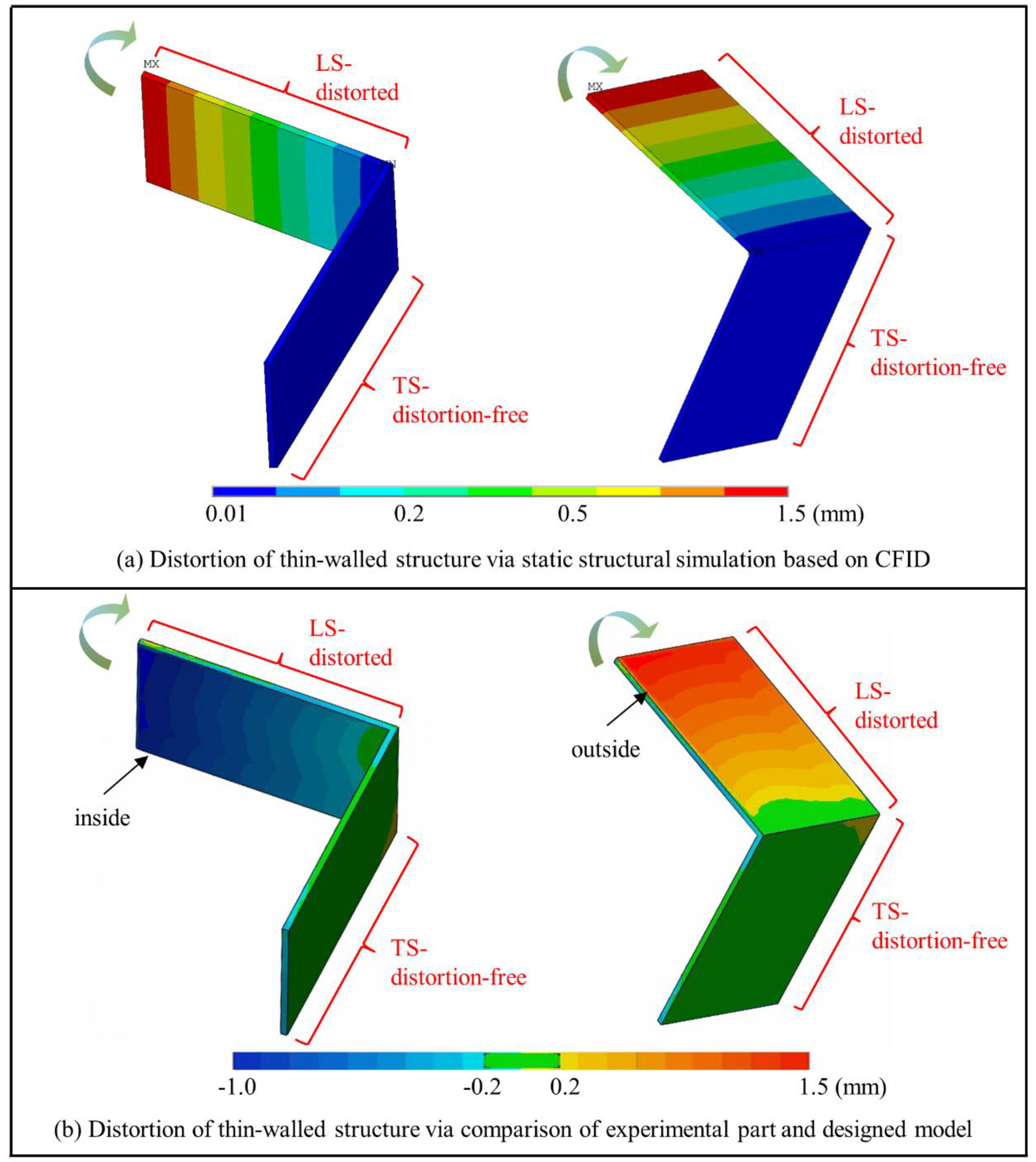
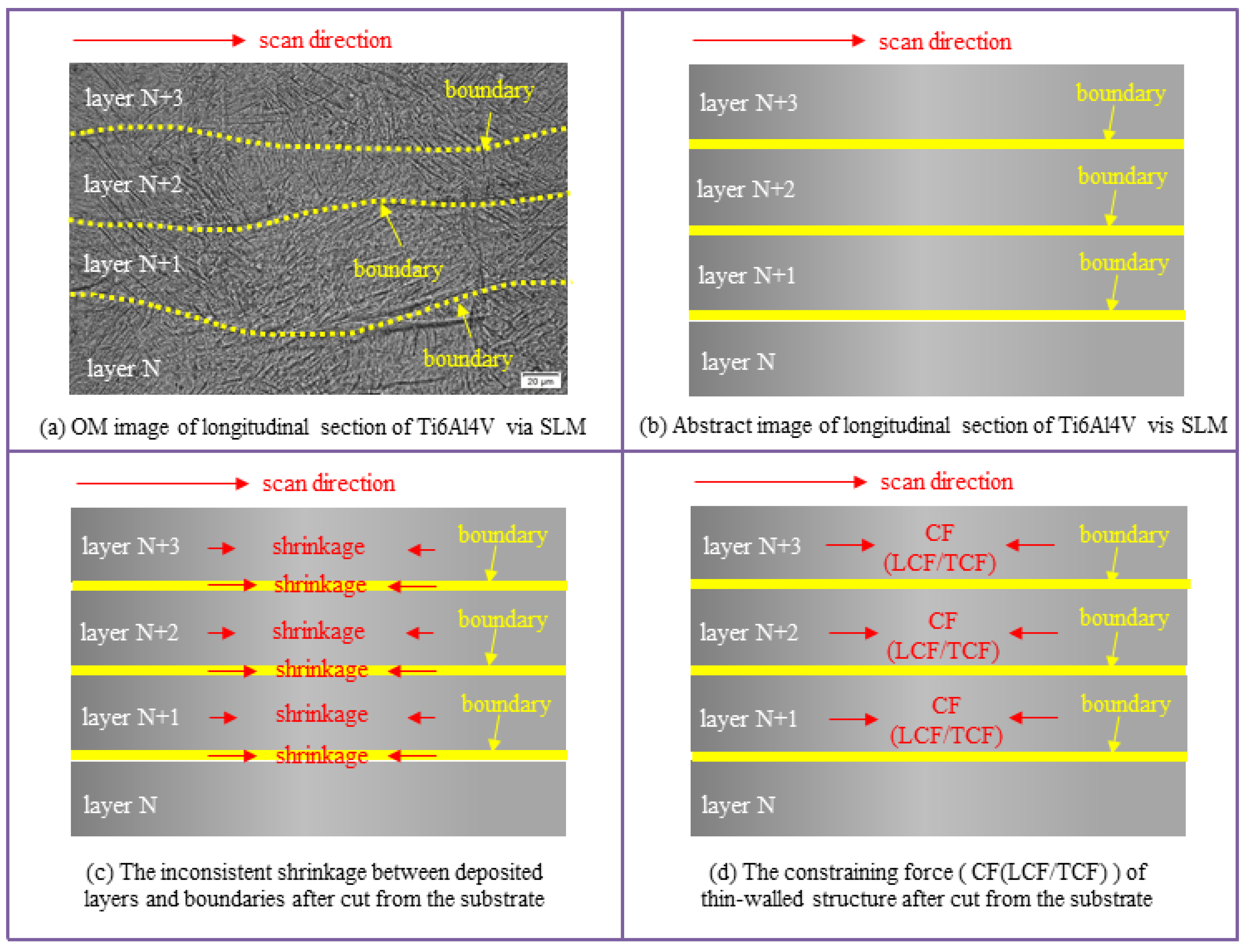
3.1. Mechanism of Distortion of Thin-Walled Structure via SLM

According to assumption of CFID, the distortion of metal additive manufacturing is caused by the constraining force, which derives from the inconsistent shrinkage in the metal part. In this section, the origin and direction of constraining force will be discussed, so that the mechanism of distortion is able to be revealed. Due to the static structural simulation based on CFID, Figure 2a demonstrates that the side with longitudinal scan (LS) was distorted, whereas the side with transverse scan (TS) was distortion-free. The comparison of experimental part and designed model shows almost the same result distortions as that of static structural simulation. As shown in Figure 2b, the body in blue means that the built part is inside the outline of designed model, whereas the body in red means that the built part is outside the outline of designed model. The two pictures in different perspectives depict that the side with LS was distorted. Besides, the side with TS was distortion-free. As a result, the assumption of CFID can be used to comprehend the distortion of thin-walled structure, as the simulated distortion is consistent with experimental results well and the numerical values of maximum distortion are almost the same. Furthermore, the different distortion caused by different laser scan strategies, i.e., LS and TS, should be valued in controlling the distortion of SLM thin-walled structure.
Afterwards, a question must be discussed—where is the inconsistent shrinkage after the thin-walled structure cut from the substrate? Suppose that the microstructure of an elastic rod in tension is totally uniform, there will be no difference in shrinkage when the rod is free of tensile force. On the contrary, if the microstructure of the rod is heterogeneous, there will be uneven strain or shrinkage inside the rod, thus causing the distortion of the rod. Therefore, the uneven microstructure can cause the macro-distortion of part.
In this study, the built thin-walled structure was free of constraint after being cut from the substrate. However, the side with LS was distorted as shown in Figure 2b. It is supposed to be caused by uneven microstructure in the built part. Figure 3a demonstrates the longitudinal section of the side with LS of Ti6Al4V. The microstructure of deposited layers (layer N, N+1, N+2, and N+3) can be viewed as uniform. However, the microstructure of molten boundaries among the adjacent layers is different from that of the deposited layers. The directions of the microstructure at boundaries are nearly parallel to the laser scan direction, whereas the microstructure of deposited layers shows no obvious directionality. After the part was cut from the substrate, the boundaries parallel to scan direction are prone to generate more shrinkage than deposited layers, as shown in Figure 3c. Then, the constraining force (CF, shown in Figure 3d) is generated, which derives from inconsistent shrinkage.
According to the origin of constraining force (CF) mentioned above, the direction of CF is parallel to the scan direction. In other words, the direction of longitudinal constraining force (LCF) in Figure 1b is parallel to longitudinal scan (LS) in Figure 1a, whereas the direction of transverse constraining force (TCF) in Figure 1b is parallel to transverse scan (TS) in Figure 1a. Based on the theory of the instability of compressive rod, the LCF acting on the side with LS is likely to form larger distortion than the TCF loading on the side with TS does. Therefore, the different distortion caused by different laser scan directions can be comprehended combined with CFID and the origin of CF, i.e., the inconsistent shrinkage due to the uneven microstructure.
The discussed origin of CF also reveals that the LCF and TCF should be uniformly distributed load (as shown in Figure 1b). Figure 3c shows that the inconsistent shrinkage may be formed in each layer because the boundaries generated layer-by-layer in metal additive manufacturing process. Thus, the CF (LCF or TCF) may exist in each layer of the built part, causing a uniformly distributed load, as demonstrated in Figure 1b.
In a word, the distortion mechanism of thin-walled structure is able to be uncovered. The distortion is the result of constraining force acting on the built thin-walled structure. The constraining force derives from the uneven microstructure in the built part. The direction of constraining force is probably parallel to the laser scan direction, and the load of constraining force is uniformly distributed due to the layer-by-layer uneven microstructure in the built part.

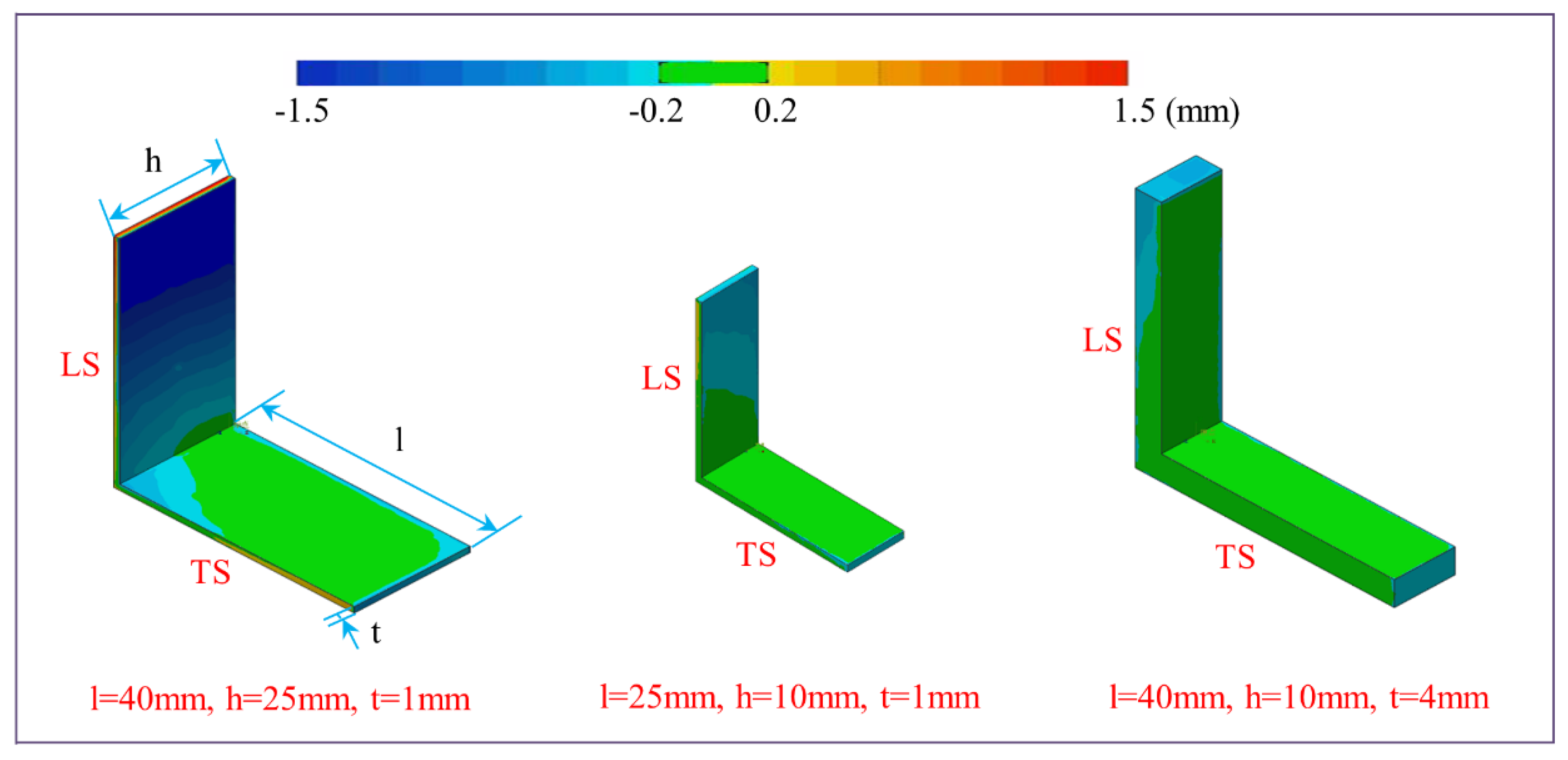
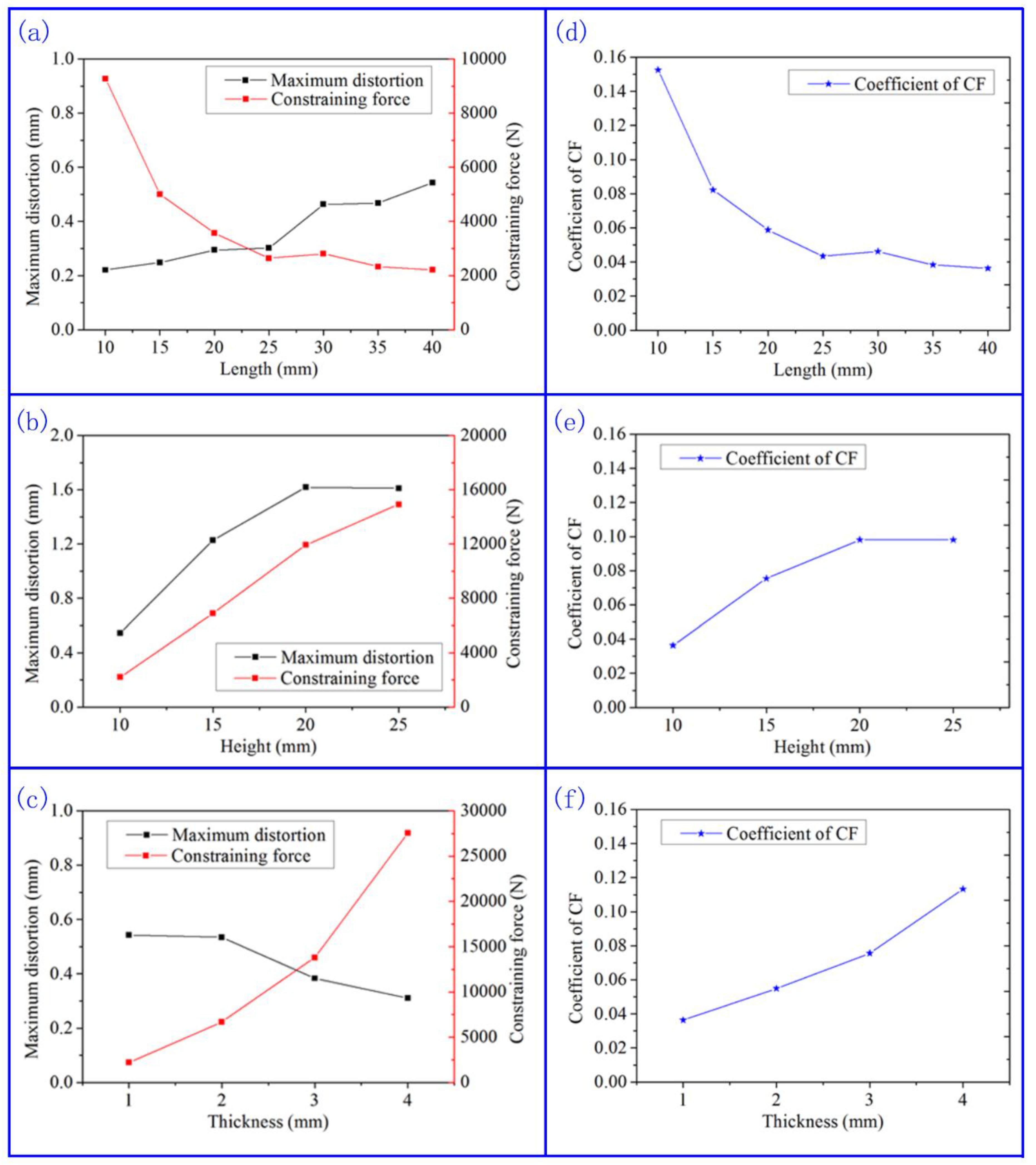
3.2. Influence of Structure Sizes on Distortion of Thin-Walled Structure

According to the assumption of CFID, the numerical value of constraining force is determined by the cross section of structure. The structure sizes are believed to be linked with the constraining force. In this section, the influence of structure sizes on constraining force and the corresponding distortion of thin-walled structure will be discussed.
Figure 4 demonstrates the experimental distortion of three thin-walled structures with various sizes as examples. It can be seen that all sides with TS show little distortion, whereas the sides with LS are prone to form obvious distortion. Besides, a longer and higher thin-walled structure is more likely to form larger distortion, and therefore a thicker structure will generate less distortion. Such a phenomenon is, initially, easy to understand based on CFID and the theory of the instability of compressive rod.
To calculate the numerical value of constraining force, the distortion of thin-walled structure can be regarded as post-buckling behavior of thin elastic shells [23,24]. In the range of small distortion, the constraining force has a linear relation with the actual maximum distortion. Combined with static structural simulations, the numerical values of constraining force of various structure sizes could be calculated, as shown in Figure 5a–c.
Furthermore, the authors of [14] also came up with a formula of constraining force as follows.
Fds = kds∙(αd∙∆T + βpt)∙Ed∙Ad
Here, Fds is the constraining force; kds is the coefficient of constraining force, which reflects the extent of inconsistent shrinkage in the built part; αd∙∆T means the shrinkage caused by thermal shrinkage; βpt represents the shrinkage caused by phase transformation; and Ed is the elastic modulus of the deposited material Ti6Al4V. Ad is the cross-section area of the built structure.
In this study,
αd∙∆T = 11.0 × 10 − 6/°C × (1680 − 20) °C = 0.0183
βpt is calculated as 2.78% [14]; Ed is ~132 GPa, which came from the test results by Nano Indentation Instrument; and Ad = h × t, as shown in Figure 1a. Therefore, the coefficients of constraining force can be calculated, as demonstrated in Figure 5d–f. It can be found out that the coefficient of CF increases when the flexural rigidity of the built structure increases. It may be attributed to that the structure with higher flexural rigidity is more difficult to release or to harmonize the inconsistent shrinkage in the built part.

3.3. Approaches to Decrease the Distortion of Thin-Walled Structure Built by SLM

According to the previous study, the distortion can be regarded as a result of constraining force acting on the built structure, as shown in Figure 6. From the perspective of constraining force, the inconsistent shrinkage is the origin of constraining force, which also reflects the value of constraining force. The scan strategy determines the direction of constraining force. From the perspective of structure, the material properties and structure sizes can influence the structural stiffness, and thus can influence the distortion.
For a thin-walled structure, the material properties and structure sizes usually have been confirmed so as to satisfy the requirements of application and environment before SLM. Thus, the attention to decrease the distortion should be paid on decreasing the value of constraining force, i.e., inconsistent shrinkage, or changing the direction of constraining force via scan strategy. To decrease the inconsistent shrinkage, the preheating of building platform and powder may be an effective approach [25]. Stress relief annealing [11] may be another method for decreasing the inconsistent shrinkage because it can homogenize the elastic strain. Based on Formula (1), other approaches can be explored such as using a smaller heat source, decreasing thermal expansion coefficient, and introducing expansive phase transformation. In terms of changing the constraining force direction, different scan strategies have been reported to be effective on decreasing the distortion [26,27,28]. Especially for the structure with sizes distinct different in X, Y, and Z directions, using different scan directions means that the constraining force can be adjusted to act on the structures with different stiffnesses, and thus can generate different distortion.
An experiment was performed to validate the deduction that different scan strategies can lead to different distortion. Figure 7a shows the two different scan strategies for fabricating the thin-walled structure. Strategy A means that every layer was built in the same scan direction with the previous layer. Strategy B means that one arm of the cross structure was built by alternant longitudinal scan and transverse scan. The according constraining forces via strategies A and B are distinctly different, as shown in Figure 7b,c. The constraining forces TCF are not demonstrated, because TCF cannot cause obvious distortion as mention before. For strategy A, the constraining forces LCF always acts on the two arms along LS, and thus can impel the two arms distorted (shown in Figure 7b). For the case of strategy B, the four arms all suffer LCF, as shown in Figure 7c. However, the strength of LCF via strategy B is half of that via strategy A. Therefore, the four arms are all distortion-free. It may due to that this half strength of LCF is less than the critical yield strength of thin-wall structure.

4. Conclusions

In this study, we discussed the mechanism of distortion of thin-walled structure built by SLM and the approaches to decrease the distortion. Some conclusions are listed as follows.
1. Based on the assumption of constraining force-induced distortion, the distortion of thin-walled structure is caused by the inconsistent shrinkage between deposited layers and molten boundaries. The link between macro-distortion and microstructure has been established.
2. The scan direction determines the direction of constraining force acting on the structure. For thin-walled structure, transverse scan is beneficial for decreasing the distortion, because transverse constraining force acts on the structure with large stiffness.
3. From the perspective of structure design, long and tall structure is suggested to be avoided, so as to decrease the distortion. If the structure sizes cannot be adjusted, using alternant scan strategy is preferred.

Author Contributions

Conceptualization, D.X. and T.Y.; Methodology, W.Y. and S.W.; Writing—Review & Editing, D.X.; L.S. and C.W.; Validation, J.Z. and P.R.

Funding

This work was supported by the National Key Research and Development Program “Additive Manufacturing and Laser Manufacturing” (Nos. 2018YFB1105400 and 2018YFB1105801), the National Natural Science Foundation of China (No. 51475238), the Key Research and Development Program of Jiangsu Provincial Department of Science and Technology of China (Nos. BE2017009 and BE2019002), and Postgraduate Education and Teaching Revolution Research Project of Nanjing University of Aeronautics and Astronautics (No. 2018YJXGG11).

Conflicts of Interest

The authors declare no conflicts of interest.

References

  1. Seifi, M.; Salem, A.; Beuth, J.; Harrysson, O.; Lewandowski, J.J. Overview of Materials Qualification Needs for Metal Additive Manufacturing. JOM 2016, 68, 1492. [Google Scholar] [CrossRef]
  2. Lewandowski, J.J.; Seifi, M. Metal Additive Manufacturing: A Review of Mechanical Properties. Annu. Rev. Mater. Res. 2016, 46, 151–186. [Google Scholar] [CrossRef]
  3. Yang, Y.; He, C.; Dianyu, E.; Yang, W.; Qi, F.; Xie, D.; Shen, L.; Peng, S.; Shuai, C. Mg bone implant: Features, developments and perspectives. Mater. Des. 2019, 185, 108259. [Google Scholar] [CrossRef]
  4. Everton, S.K.; Hirsch, M.; Stravroulakis, P.; Leach, R.K.; Clare, A.T. Review of in-situ process monitoring and in-situ metrology for metal additive manufacturing. Mater. Des. 2016, 95, 431–445. [Google Scholar] [CrossRef]
  5. Shuai, C.; Cheng, Y.; Yang, Y.; Peng, S.; Yang, W.; Qi, F. Laser additive manufacturing of Zn-2Al part for bone repair: Formability, microstructure and properties. J. Alloy. Compd. 2019, 798, 606–615. [Google Scholar] [CrossRef]
  6. Yang, Y.; Guo, X.; He, C.; Gao, C.; Shuai, C. Regulating degradation behavior by incorporating mesoporous silica for mg bone implants. ACS Biomater. Sci. Eng. 2018, 4, 1046–1054. [Google Scholar] [CrossRef]
  7. Liang, H.; Yang, Y.; Xie, D.; Lin, L.; Mao, N.; Wang, C.; Tian, Z.; Jiang, Q.; Shen, L. Trabecular-like Ti-6Al-4V scaffolds for orthopedic: Fabrication by selective laser melting and in vitro biocompatibility. J. Mater. Sci. Technol. 2019, 35, 1284–1297. [Google Scholar] [CrossRef]
  8. Yang, Y.; Yuan, F.; Gao, C.; Feng, P.; Xue, L.; He, S.; Shuai, C. A combined strategy to enhance the properties of Zn by laser rapid solidification and laser alloying. J. Mech. Behav. Biomed. Mater. 2018, 82, 51–60. [Google Scholar] [CrossRef]
  9. Yakout, M.; Elbestawi, M.A.; Veldhuis, S.C. A Review of Metal Additive Manufacturing Technologies. Solid State Phenom. 2018, 278, 1–14. [Google Scholar] [CrossRef]
  10. Mercelis, P.; Kruth, J.P. Residual stresses in selective laser sintering and selective laser melting. Rapid Prototyp. J. 2006, 12, 254–265. [Google Scholar] [CrossRef]
  11. Kruth, J.-P.; Deckers, J.; Yasa, E.; Wauthle, R. Assessing Influencing Factors of Residual Stresses in SLM Using a Novel Analysis Method. Proc. IMechE Part B J. Eng. Manuf. 2012, 226, 980–991. [Google Scholar] [CrossRef]
  12. Biegler, M.; Graf, B.; Rethmeier, M. In-situ distortion in LMD additive manufacturing walls can be measured with digital image correlation and predicted using numerical simulations. Addit. Manuf. 2018, 20, 101–110. [Google Scholar] [CrossRef]
  13. Denlinger, E.R.; Heigel, J.C.; Michaleris, P.; Palmer, T.A. Effect of inter-layer dwell time on distortion and residual stress in additive manufacturing of titanium and nickel alloys. J. Mater. Process. Technol. 2015, 215, 123–131. [Google Scholar] [CrossRef]
  14. Xie, D.; Zhao, J.; Liang, H.; Tian, Z.; Shen, L.; Xiao, M.; Ahsan, M.N.; Wang, C. Assumption of constraining force to explain distortion in laser additive manufacturing. Materials 2018, 11, 2327. [Google Scholar] [CrossRef]
  15. Clijsters, S.; Craeghs, T.; Moesen, M.; Kruth, J.P. Optimization of thin wall structures in SLM. J. Math. Sci. 2012, 104, 847–880. [Google Scholar]
  16. Liu, J.; Li, L. Effects of powder concentration distribution on fabrication of thin-wall parts in coaxial laser cladding. Opt. Laser Technol. 2005, 37, 287–292. [Google Scholar] [CrossRef]
  17. Chao, Y.-P.; Qi, L.-H.; Xiao, Y.; Luo, J.; Zhou, J.-M. Manufacturing of micro thin-walled metal parts by micro-droplet deposition. J. Mater. Process. Technol. 2012, 212, 484–491. [Google Scholar] [CrossRef]
  18. Abele, E.; Stoffregen, H.A.; Kniepkamp, M.; Lang, S.; Hampe, M. Selective laser melting for manufacturing of thin-walled porous elements. J. Mater. Process. Technol. 2015, 215, 114–122. [Google Scholar] [CrossRef]
  19. Yadroitsev, I.; Shishkovsky, I.; Bertrand, P.; Smurov, I. Manufacturing of finestructured 3D porous filter elements by selective laser melting. Appl. Surf. Sci. 2009, 255, 5523–5527. [Google Scholar] [CrossRef]
  20. Li, Z.; Xu, R.; Zhang, Z.; Kucukkoc, I. The influence of scan length on fabricating thin-walled components in selective laser melting. Int. J. Mach. Tools Manuf. 2018, 126, 1–12. [Google Scholar] [CrossRef]
  21. Forde, B.W.R.; Stiemer, S.F. Improved arc length orthogonality methods for nonlinear finite element analysis. Comput. Struct. 1987, 27, 625–630. [Google Scholar] [CrossRef]
  22. Xu, C.; Ye, G.B. Deformation and bearing capacity of composite foundation with cement-soil mixed pile. Chin. J. Eng. 2005, 27, 600. [Google Scholar]
  23. Newell, A.C.; Lange, C.G. The Post-Buckling Problem for Thin Elastic Shells. SIAM J. Appl. Math. 1971, 21, 605–629. [Google Scholar]
  24. Turvey, G.J.; Wittrick, W.H. The Large Deflection and Post-Buckling Behavior of Some Laminated Plates. Aeronaut. Q. 1973, 24, 77–86. [Google Scholar] [CrossRef]
  25. Zhang, K.; Wang, S.; Liu, W.; Long, R. Effects of substrate preheating on the thin-wall part built by laser metal deposition shaping. Appl. Surf. Sci. 2014, 317, 839–855. [Google Scholar] [CrossRef]
  26. Nickel, A.H.; Barnett, D.M.; Prinz, F.B. Thermal stresses and deposition patterns in layered manufacturing. Mater. Sci. Eng. A 2001, 317, 59–64. [Google Scholar] [CrossRef]
  27. Gao, M.; Wang, Z.; Li, X.; Zeng, X. The Effect of Deposition Patterns on the Deformation of Substrates During Direct Laser Fabrication. ASME. J. Eng. Mater. Technol. 2013, 135, 034502. [Google Scholar] [CrossRef]
  28. Yan, H.; Shen, L.; Wang, X.; Tian, Z.; Xu, G.; Xie, D.; Liang, H. Stress and deformation evaluation of the subarea scanning effect in direct laser-deposited Ti-6Al-4V. Int. J. Adv. Manuf. Technol. 2018, 97, 91–96. [Google Scholar] [CrossRef]
Figure 1. Scan strategy and built thin-walled structure via selective laser melting (SLM).
Metals 09 01281 g001
Figure 2. Distortion of thin-walled structure via simulation and experiment (after cut).
Metals 09 01281 g002
Figure 3. Mechanism of distortion of thin-walled structure.
Metals 09 01281 g003
Figure 4. Experimental distortion of three sampled thin-walled structures.
Metals 09 01281 g004
Figure 5. Distortion of thin-walled structure with various sizes. (ac), the distortions and constraining force of thin-walled structure with various sizes. (df), the coefficient of constraining force of thin-walled structure with various sizes.
Metals 09 01281 g005
Figure 6. Influencing factors of distortion of thin-walled structure.
Metals 09 01281 g006
Figure 7. Influence of scan strategy on the distortion of thin-walled structure.
Metals 09 01281 g007

