Abstract
This paper describes the methodology for conducting experiments to study hydrogen diffusion through metal membranes using a specially designed diffusion chamber of an automated gas reaction controller complex. This complex allows experiments to study hydrogen diffusion with the following parameters: the inlet hydrogen pressure is up to 50 atmospheres, and the temperature in the chamber is from 30 °C to 1000 °C. The size of the samples is limited to a diameter of 10 mm and a thickness of 100 μm. The method for calculating the diffusion coefficient based on the Fick equation is also described. When studying hydrogen diffusion through a sample of Zr–1Nb alloy with nickel film deposited at the temperature of 550 °C, it was noted that phase transformations can be observed on the diffusion curve.
1. Introduction
The study of the interaction of hydrogen with metals and alloys is widespread in the world [1,2,3,4]. This interaction is considered in two directions. On the one hand, in relation to the development of hydrogen energy, the study of new hydrogen storage materials is necessary [5,6,7]. In addition, the development of hydrogen purification systems is of great relevance. On the other hand, hydrogen has a negative effect on the crystal lattices of metals, thereby leading to embrittlement of materials [8,9,10]. Therefore, it is necessary to develop various protective coatings, make surface modifications, etc.
Zirconium alloys are widely used in reactor engineering in the form of shells of fuel carriers [11]. This is due to high strength and corrosion resistance of the material, as well as the low thermal neutron capture cross section. Operating at high temperatures [12], reactors with water-based coolant can provoke steam–zirconium reactions with hydrogen evolution [13,14,15,16,17,18]. Therefore, one of the important requirements for zirconium alloys is resistance for hydrogen penetration and embrittlement [19,20,21,22].
One of the factors that affect the level of hydrogenation of zirconium alloys is the state of their surface, namely an oxide film [21,22]. In the presence of a continuous thin oxide film on the surface, zirconium alloys weakly absorb hydrogen, even at high temperatures [23]. Using nickel coatings, one can get rid of the limiting factor of the surface [24]. This is due to the fact that during the coating process, the surface of the test sample undergoes ion cleaning, which leads to the removal of a thin layer that has accumulated various adsorbates, including oxygen. The thin nickel film itself prevents the accumulation of new adsorbates that directly affect diffusion.
In this paper, we describe the methodology for conducting experiments on the study of high-temperature diffusion using the gas reaction controller (GRC) complex. The methodology for calculating the diffusion coefficient using mass spectrometric analysis as a hydrogen analyzer is described. Additionally, for the first time, a hydrogen diffusion process in zirconium alloy is experimentally correlated with phase transformation in the zirconium alloy during hydrogenation.
There are several methods for studying the diffusion of hydrogen through metal membranes. One of these methods is the study of diffusion using electrochemical penetration. The use of this method has been implemented in many experimental facilities [25,26,27]. Its principle of operation is as follows: between the two electrochemical compartments, the studied metal foil is placed, which is hermetically fixed relative to the two compartments due to the special design of the holder. When direct current flows through the electrolyte, the electrolyte dissociates with the release of hydrogen ions on the metal foil and precipitation of the acid residue on the anode, i.e., hydrogen ions are deposited on the input side of the investigated metal foil (cathode side). Subsequently, due to diffusion processes, hydrogen begins to penetrate through the membrane, and after a certain period of time, exits the anode side of the membrane into the cathode compartment, where it is released at the cathode. The advantages of this method are that it is simple and provides the ability to study the diffusion of hydrogen in aggressive environments. Among the limitations of this method to be mentioned is the impossibility to change the temperature of the experiment.
One can also point out another similar method for studying the diffusion of hydrogen through metal membranes. The main difference from the previous method is the use of a mass spectrometer as an identifier for released hydrogen. The principle of operation of an experimental setup for studying hydrogen permeability through a metal membrane by electrochemical penetration and mass spectrometric analysis [28,29] is as follows. The investigated metal foil is placed between the two compartments and is hermetically fixed due to the design of the installation. When the circuit is closed, direct current flows through the electrolyte in the first compartment, and as a result, hydrogen ions are released on the metal membrane, which is the cathode, and the acid residue is deposited on the anode. Over a certain period of time, due to diffusion processes, hydrogen penetrates deep into the crystalline structure of the membrane and passes through its entire thickness, thereby falling into the second compartment of the high-vacuum chamber. An important feature of this method is that it is possible to study the interaction of hydrogen isotopes and metals.
Another method for studying hydrogen permeability through metal membranes has also been implemented in many experimental facilities [30,31]. An important distinguishing feature of it is the study of the interaction of metals with hydrogen in the gas phase. This type of experimental complex enables the study of the effect of various processes of unilateral hydrogenation of a metal membrane on various protective coatings using a wide range of different saturation parameters, which helps the study of metal–hydrogen systems in even more detail. It is also of interest to study the sorption– desorption of gases during their permeability through the studied foils. For this, the experimental complexes are equipped with a mass spectrometer located directly in the vacuum system of the plants. The principle of its operation is similar to the principle of operation of all mass spectrometers for measuring the pressure of residual gases: a few gas molecules are ionized (positive ions), ions are separated by their masses, and ion currents are measured for each mass. Compared to previous installations, the implementation of this type of installation is more expensive.
2. Materials and Research Methods
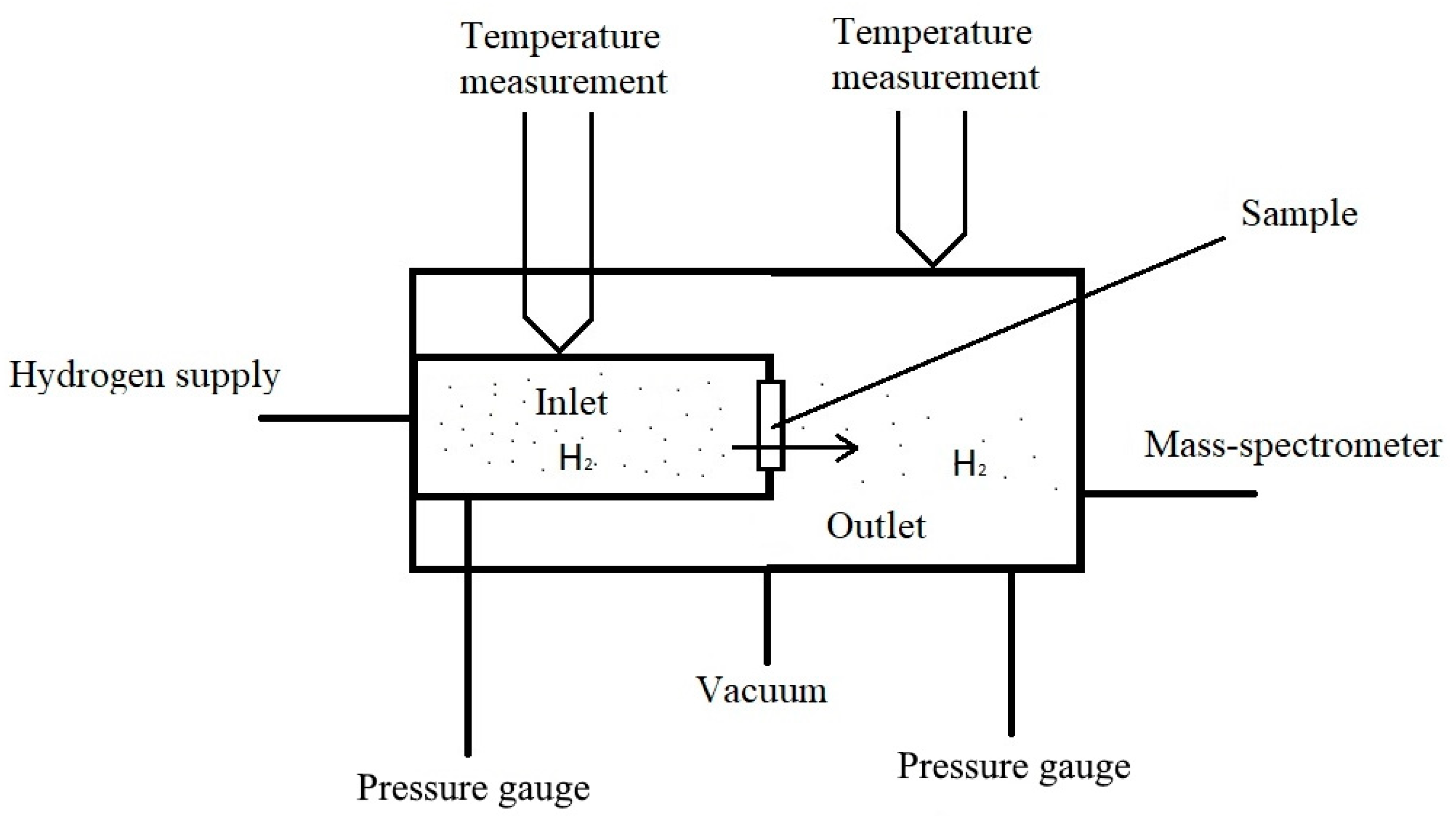
Using a modified gas chamber, which is described below, it is possible to study the diffusion of hydrogen at various temperatures. The principle of operation of most installations for the diffusion of hydrogen from the gas phase can be understood from Figure 1.
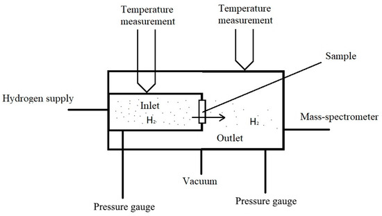
Figure 1.
The principle of operation of installation for the study of diffusion from a gaseous medium.
The following method is used to study hydrogen diffusion: after sample preparation, it is fixed between the input and output volumes. Next, these volumes are evacuated and heated to the operating temperature. After heating, hydrogen is introduced into the inlet of the chamber. At the same time, the pressure of hydrogen passing through the sample is measured from the output side using mass spectrometric registration. In this method, finding the hydrogen permeability parameters reduces to solving the Fick equation [32,33] with boundary conditions of the first kind:
At the input side of the sample, a concentration equal to the equilibrium solubility is instantly established, and at the initial side of the sample, the hydrogen concentration is zero.
In accordance with Fick’s first law, the flow of hydrogen through a unit area membrane is written as follows:
For the flow on the output side of the membrane, based on Fick’s first law, we have the expression:
To calculate the diffusion coefficient, you can use the value of the stationary flow, which has the following expression:
Studying the dependence J(t) (Figure 2), we can distinguish the characteristic point, which is the time of establishment of half of the stationary flow t0.5.
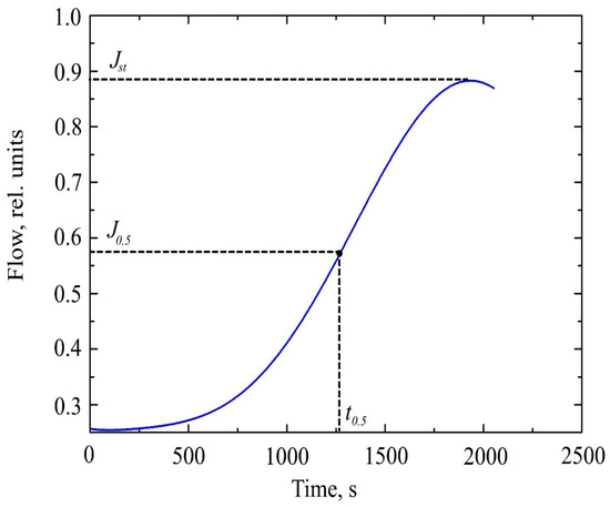
Figure 2.
The curve of hydrogen permeability through a metal membrane.
In studies using mass spectrometric analysis for diffusion from a medium with a constant concentration, the expression has the following form [34]:
The value of the coefficient Z is found from the table of the probability integral function erf (Z) = x (where x is the error in determining the flux by mass spectrometric analysis), and l is the thickness of the sample.
To plot the dependences J(t), it is necessary to represent the pressure on the output side of the sample in the form of a hydrogen stream. To do this, we use the Mendeleev–Klaiperon equation [35]:
where p is the pressure of hydrogen in the output volume, V is the volume of the output part of the camera, ν is the amount of hydrogen, R is the universal gas constant, and T is the temperature in the chamber.
Expressing ν from Equation (8) we get:
The flow of hydrogen can be calculated as the flow of gas that varies over time. Knowing the amount of hydrogen and time, we get:
where Δt is the time during which change in the amount of hydrogen occurs.
To study hydrogen permeability, the GRC automated complex was used. This complex allows the study of the interaction of hydrogen with structural materials at temperatures from 300 K to 1223 K and an inlet pressure of hydrogen up to 50 atm.
This stand consists of a vacuum system, a hydrogen generator, and a personal computer for controlling gas inlet and exhaust systems.
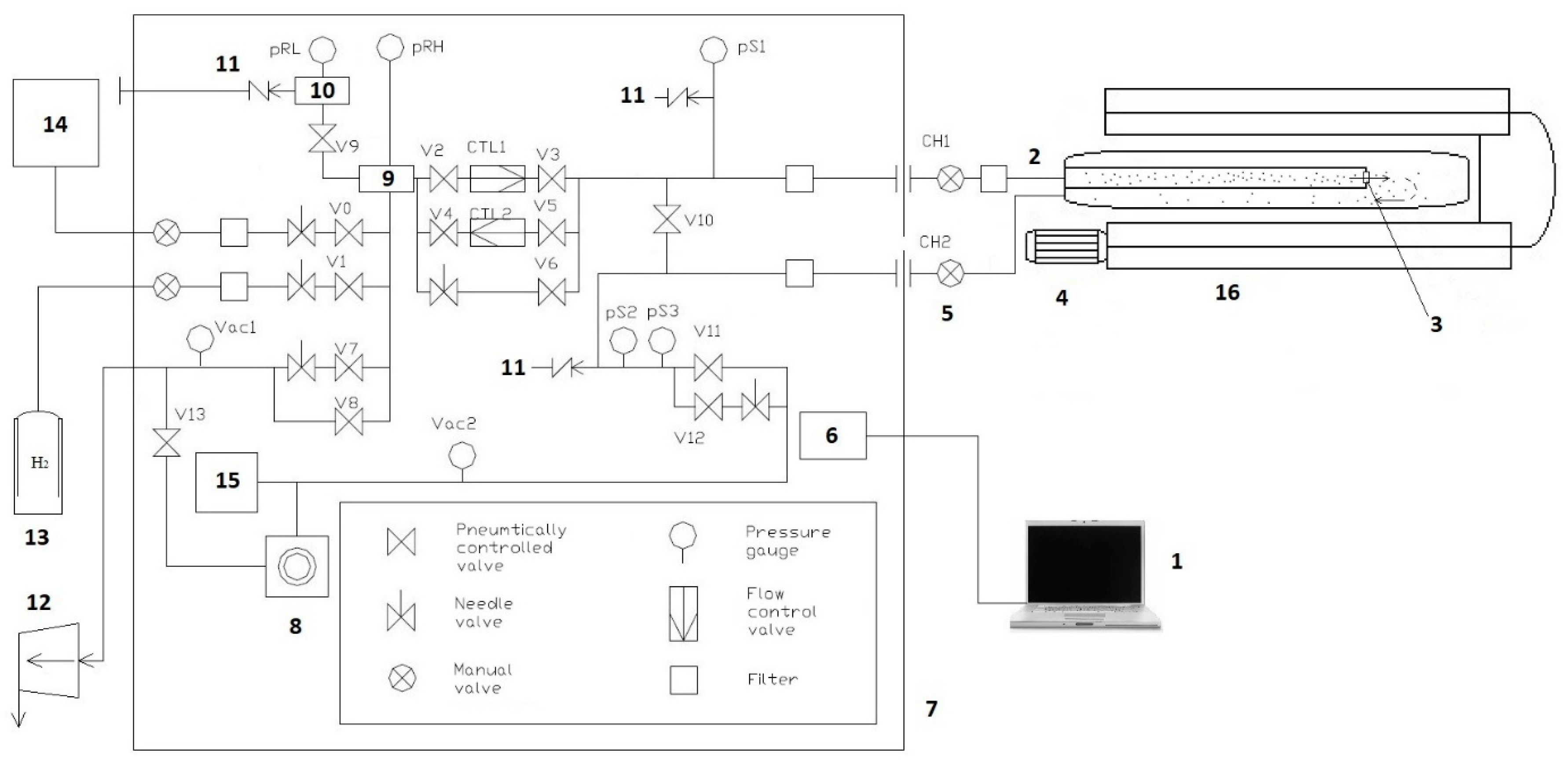
The GRC vacuum system (Figure 3) allows you to create the necessary conditions for the experiment. HyGen 200 (CLAIND srl, Lenno, Italy) hydrogen generator allows the use of spectrally pure (99.9999%) hydrogen, which improves the accuracy of the experiment. A personal computer provides control of the parameters of the experiment during operation and also serves to record the received data.

Figure 3.
Scheme of the automated gas reaction controller complex: 1, computer; 2, connecting tube of the input volume; 3, camera; 4, fan; 5, connecting tube of the output volume; 6, electronic control system of the complex: 7, controller; 8, high vacuum pump; 9, high pressure tank; 10, low pressure tank; 11, emergency hydrogen removal system; 12, foreline pump; 13, cylinder with hydrogen; 14, hydrogen generator; 15, mass spectrometer; and 16, high temperature furnace.
Registration of gases on the output side of the sample is carried out using a mass spectrometer connected to the output volume of the working chamber, and allows one to determine the residual gas pressure within a pressure range from 10−4 to 10−8 mtorr. A high-temperature furnace ensures implementation of the temperatures necessary for conducting experiments with preliminary annealing of the samples.
After the steady-state flow is established, the registration of hydrogen ceases, and the remaining hydrogen is pumped out. The temperature also drops to room temperature in order for the experimental sample to be extracted.
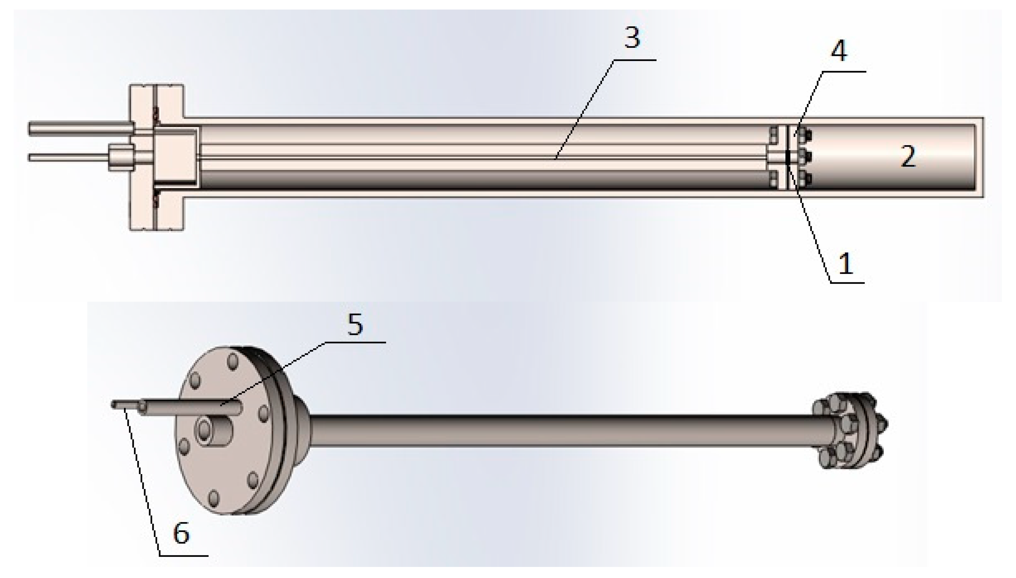
In this work, we used a modified gas chamber (Figure 4) developed at the Department for Experimental Physics within the School of Nuclear Science and Engineering at National Research Tomsk Polytechnic University (NR TPU).
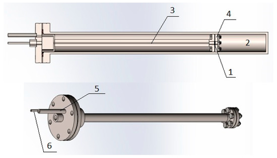
Figure 4.
Modified vacuum chamber: 1, sample; 2, output volume; 3, input volume; 4, pressure plate; 5, connecting tube of the input volume; and 6, connecting tube output volume.
To solve the problems associated with the study of hydrogen diffusion, the following experimental procedure is implemented.
Preparation of experimental samples. Cylindrical samples of Zr–1Nb alloy with diameters of 10 mm are subjected to thinning by grinding to the thickness of 100 μm to impart a smooth surface using sandpaper with markings according to ISO-6344 600, 1500, 2000, and 2500. Next, magnetron sputtering is applied to the surface of the nickel layer [24].
Preparing the installation. To study the permeability of hydrogen, a modified vacuum chamber is used, shown in Figure 5. The test sample is placed between the inlet and outlet volumes. Then, it is fixed with the help of plate 7. Gases are pumped out from the chamber through tubes 5 and 6 to a pressure of the order of 10−6 mbar. Using a high-temperature furnace, the gas chamber is heated to the required temperature.
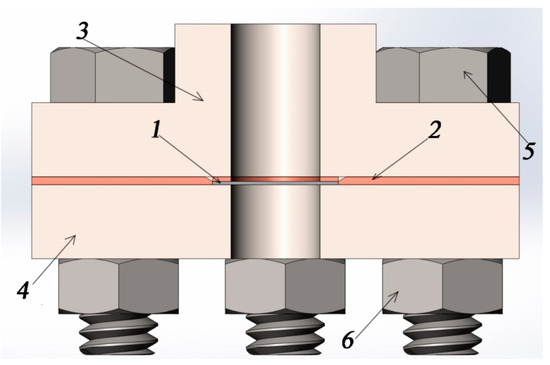
Figure 5.
Assembly of the sample in the vacuum chamber in the context: 1, sample; 2, copper gasket; 3, vacuum flange; 4, pressure flange; 5, bolt; and 6, nut.
Hydrogen inlet. Using a hydrogen generator, hydrogen is supplied to the input chamber volume. Simultaneously, the registration of the hydrogen pressure from the output side of the sample begins, using a mass spectrometer. On the other hand, a parallel study of the processes of unilateral hydrogen distillation of experimental samples is possible. For this, hydrogen pressure is recorded in the inlet volume of the gas chamber. This allows one to calculate the sorption rate.
3. Results and Discussion
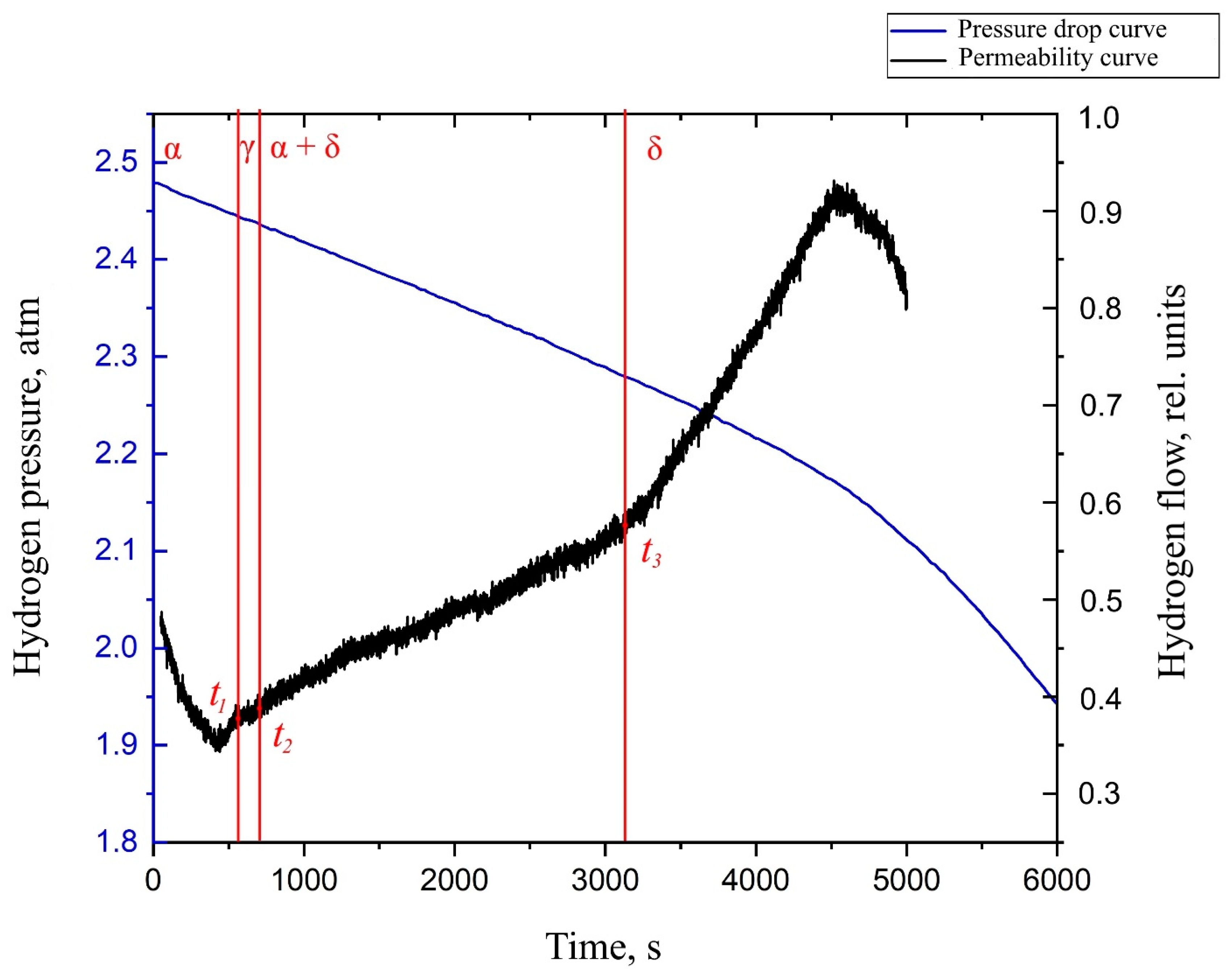
By analyzing the obtained diffusion curve for the Zr–1Nb alloy with a nickel coating deposited on the surface (Figure 6), several characteristic points can be distinguished. These points are associated with the change in the value of the tangent to the graph of the flow function versus time. The point t1 characterizes the beginning of the transformation of the α phase of zirconium into a metastable γ phase. Point t2 characterizes the beginning of diffusion in the α + δ phase of zirconium. Point t3 characterizes the complete transformation of the α phase into the δ phase.
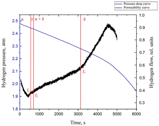
Figure 6.
The hydrogen permeability curve in the Zr–1Nb alloy with a thin layer of nickel deposited on the surface at the temperature of 550 °C.
These points correlate well with the experimental data obtained by applying synchrotron irradiation for X-ray diffraction during the hydrogenation of the Zr–1Nb alloy from the gas medium [36]. At the temperature of 550 °C, the following data are available (Figure 7). From the graph, it can be noted that during the hydrogenation of the studied samples, the lifetime of the α phase is limited to 10 min. The metastable γ phase exists for no more than 5 min. Further, one can notice the presence of δ zirconium hydride.
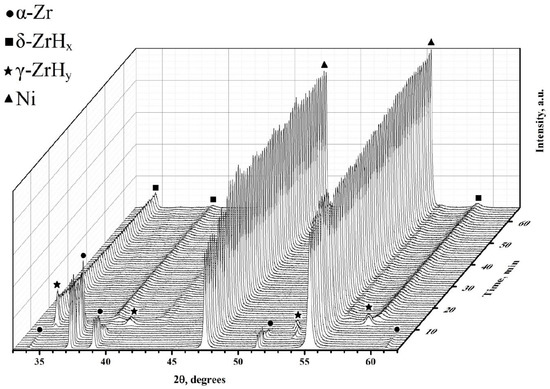
Figure 7.
Phase transitions in the Zr–H system with a Ni layer during hydrogenation at a temperature of 550 °C.
The hydrogen diffusion coefficients were determined from the critical points of the function of the dependence of the hydrogen flow on the duration of one-sided hydrogenation.
You can also notice that the rate of change of pressure in the inlet volume changes only after the completion of all phase transformations and complete breakthrough of hydrogen through δ-zirconium hydride. This may indicate that the rate of hydrogen sorption in the different phases of zirconium is the same.
Comparative data are presented in Table 1.

Table 1.
Comparative data on the phase transition time for various methods for studying metal– hydrogen systems.
Using Expression (9), we calculate the diffusion coefficient for α and δ phases of zirconium. We find the coefficient Z as an argument of the probability integral, the value of which is the maximum error in determining the flow function of time.
The data obtained are presented in Table 2.
Table 2.
The obtained parameters in the study of diffusion in α and δ zirconium.
In the case of α-zirconium, the difference in diffusion coefficients is not significant, which indicates the efficiency of the calculation method. In the case of α + δ-zirconium hydride, diffusion is aimed only at the accumulation of hydrogen in the material and stabilization of δ-zirconium hydride. The difference in diffusion coefficients in zirconium δ-hydride is as follows: theoretical data were obtained for the already stable δ-hydride, and experimental data were obtained during phase transformations of α-zirconium in δ-hydride. In this case, diffusing hydrogen is already present in the test sample; therefore, one can only notice a change in the diffusion rate.
4. Summary
In this work, we tested the methodology for calculating the diffusion coefficient of hydrogen in metal foils at high temperatures using a mass spectrometer as a hydrogen recorder. For the first time, the hydrogen diffusion process in zirconium alloy was experimentally correlated with phase transformation in the zirconium alloy during hydrogenation. We can also conclude that for non-hydride-forming materials, the results obtained using this technique can be correlated with theoretical data.
In the case of hydride-forming materials, in some cases, one can observe phase transformations, namely the lifetime of some phases during unilateral hydrogen distillation. The data obtained are well correlated with theoretical data, which indicates the efficiency of this technique.
The difference between experimental and theoretical data lies in sample preparation. From this, we can conclude that this technique, ceteris paribus, rather than providing solutions to fundamental problems, is more of a comparative method of study.
Author Contributions
V.K. made the organization of the workflow and preparation of the article; I.S. conducted experiments on hydrogen permeability; and G.G. and A.L. made an analysis of the results.
Funding
The research was funded by the governmental program “Science”, research project No. 11.3683.2017/4.6.
Acknowledgments
The research was carried out within the framework of the Program for Enhancing Competitiveness of Tomsk Polytechnic University.
Conflicts of Interest
The authors declare no conflict of interest.
References
- Besenbacher, F.; Myers, S.M.; Nørskov, J.K. Interaction of hydrogen with defects in metals. Nucl. Instrum. Methods Phys. Res. Sect. B 1985, 7, 55–66. [Google Scholar] [CrossRef]
- Wu, C.; Wang, Q.; Mao, Y.; Huang, L.; Chen, Y.; Dai, X. Relationship between lattice defects and phase transformation in hydrogenation/dehydrogenation process of the V60Ti25Cr3Fe12 alloy. Int. J. Hydrogen Energy 2019, 44, 9368–9377. [Google Scholar] [CrossRef]
- Nørskov, J.K.; Besenbacher, F. Theory of hydrogen interaction with metals . J. Less Common Met. 1987, 130, 475–490. [Google Scholar] [CrossRef]
- Christmann, K. Interaction of hydrogen with solid surfaces. Surf. Sci. Rep. 1988, 9, 1–163. [Google Scholar] [CrossRef]
- Kudiiarov, V.N.; Syrtanov, M.S.; Bordulev, Y.S.; Babikhina, M.N.; Lider, A.M.; Gubin, V.E.; Murashkina, T.L. The hydrogen sorption and desorption behavior in spherical powder of pure titanium used for additive manufacturing. Int. J. Hydrogen Energy 2017, 42, 15283–15289. [Google Scholar] [CrossRef]
- Tarasov, B.P.; Arbuzov, A.A.; Mozhzhuhin, S.A.; Volodin, A.A.; Fursikov, P.V.; Lototskyy, M.V.; Yartys, V.A. Hydrogen storage behavior of magnesium catalyzed by nickel-graphene nanocomposites. Int. J. Hydrogen Energy 2019, 44, 29212–29223. [Google Scholar] [CrossRef]
- Ren, J.; Musyoka, N.M.; Langmi, H.W.; Mathe, M.; Liao, S. Current research trends and perspectives on materials-based hydrogen storage solutions: A critical review. Int. J. Hydrogen Energy 2017, 42, 289–311. [Google Scholar] [CrossRef]
- Louthan, M.R.; Caskey, G.R.; Donovan, J.A.; Rawl, D.E. Hydrogen embrittlement of metals. Mater. Sci. Eng. 1972, 10, 357–368. [Google Scholar] [CrossRef]
- Rogne, B.R.S.; Kheradmand, N.; Deng, Y.; Barnoush, A. In situ micromechanical testing in environmental scanning electron microscope: A new insight into hydrogen-assisted cracking. Acta Mater. 2018, 144, 257–268. [Google Scholar] [CrossRef]
- Teichmann, N.; Hamm, M.; Pundt, A. Fast lateral hydrogen diffusion in magnesium-hydride films on sapphire substrates studied by electrochemical hydrogenography. Int. J. Hydrogen Energy 2018, 43, 1634–1642. [Google Scholar] [CrossRef]
- Zieliński, A.; Sobieszczyk, S. Hydrogen-enhanced degradation and oxide effects in zirconium alloys for nuclear applications. Int. J. Hydrogen Energy 2011, 36, 8619–8629. [Google Scholar] [CrossRef]
- Tong, L.S.; Weisman, J. Thermal Analysis of PRESSURIZED Water Reactors; American Nuclear Society: La Grange Park, IL, USA, 1979. [Google Scholar]
- Neeb, K.H. The Radiochemistry of Nuclear Power Plants with Light Water Reactors; Walter de Gruyter: Berlin, Germany, 2011. [Google Scholar]
- Woodtli, J.; Kieselbach, R. Damage due to hydrogen embrittlement and stress corrosion cracking. Eng. Fail. Anal. 2000, 7, 427–450. [Google Scholar] [CrossRef]
- Nagase, F. Hydride behavior in Zircaloy cladding tube during high-temperature transients. J. Nucl. Mater. 2011, 415, 117–122. [Google Scholar] [CrossRef]
- Daum, R.S.; Bates, D.W.; Koss, D.A.; Motta, A.T. The influence of a hydride layer on the fracture of zircaloy-4 cladding tubes. In Proceedings of the International Conference on Hydrogen Effects on Material Behaviour and Corrosion Deformation Interactions, Moran, WY, USA, 22–26 September 2002. [Google Scholar]
- Motta, A.T.; Chen, L.Q. Hydride formation in zirconium alloys. J. Miner. Met. Mater. Soc. 2012, 64, 1403–1408. [Google Scholar] [CrossRef]
- Nagase, F.; Fuketa, T. Investigation of hydride rim effect on failure of Zircaloy-4 cladding with tube burst test J. Nucl. Sci. Technol. 2005, 42, 58–65. [Google Scholar] [CrossRef]
- Hanson, B.; Shimskey, R.; Lavender, C.; MacFarlan, P.; Eslinger, P. Hydride Rim Formation in Unirradiated Zircaloy; Pacific Northwest National Laboratory: Richland, WA, USA, 30 April 2013. [Google Scholar]
- Shimskey, R.W.; Hanson, B.D.; MacFarlan, P.J. Optimization of Hydride Rim Formation in Unirradiated Zr 4 Cladding; Pacific Northwest National Laboratory: Richland, WA, USA, 30 September 2013. [Google Scholar]
- Chernov, I.P.; Cherdantsev, Y.P.; Lider, A.M.; Tyurin, Y.I.; Pushilina, N.S.; Ivanova, S.V. Hydrogen permeability of protective coating formed by electron treatment of zirconium alloys. J.Surf. Investig. X-ray Synchrotron Neutron Tech. 2010, 4, 255–261. [Google Scholar] [CrossRef]
- Alefeld, G.; Völkl, J. Hydrogen in Metals I-Basic Properties; Springer: Berlin, Germany, 1978. [Google Scholar]
- Warr, B.D.; Elmoselhi, M.B.; Newcomb, S.B.; McIntyre, N.S.; Brennenstuhl, A.M.; Lichtenberger, P.C. Oxide characteristics and their relationship to hydrogen uptake in zirconium alloys. In Zirconium in the Nuclear Industry, Proceedings of the Ninth International Symposium, Kobe, Japan, 5–8 November 1990; ASTM International: West Conshohocken, PA, USA, 1991. [Google Scholar]
- Kudiiarov, V.N.; Kashkarov, E.B.; Syrtanov, M.S.; Lider, A.M. Hydrogen sorption by Ni-coated titanium alloy VT1-0. Int. J. Hydrogen Energy. 2017, 42, 10604–10610. [Google Scholar] [CrossRef]
- Olden, V.; Alvaro, A.; Akselsen, O.M. Hydrogen diffusion and hydrogen influenced critical stress intensity in an API X70 pipeline steel welded joint–Experiments and FE simulations. Int. J. Hydrogen Energy 2012, 37, 11474–11486. [Google Scholar] [CrossRef]
- Mohtadi-Bonab, M.A.; Szpunar, J.A.; Collins, L.; Stankievech, R. Evaluation of hydrogen induced cracking behavior of API X70 pipeline steel at different heat treatments. Int. J. Hydrogen Energy 2014, 39, 6076–6088. [Google Scholar] [CrossRef]
- Zhao, W.; Zhang, T.; He, Z.; Sun, J.; Wang, Y. Determination of the critical plastic strain-induced stress of X80 steel through an electrochemical hydrogen permeation method. Electrochim. Acta 2016, 214, 336–344. [Google Scholar] [CrossRef]
- El Alami, H.; Creus, J.; Feaugas, X. Influence of the plastic strain on the hydrogen evolution reaction on polycrystalline nickel electrodes in H2S04. Electrochim. Acta 2006, 51, 4716–4727. [Google Scholar] [CrossRef]
- Nikitenkov, N.N.; Hashhash, A.M.; Shulepov, I.A.; Khoruzhii, V.D.; Tyurin, Y.I.; Chernov, I.P.; Kudryavtseva, E.N. A plant for studying radiation and thermal desorption of gases from inorganic materials. Instrum. Exp. Tech. 2009, 52, 865. [Google Scholar] [CrossRef]
- Nayebossadri, S.; Speight, J.D.; Book, D. Hydrogen separation from blended natural gas and hydrogen by Pd-based membranes. Int. J. Hydrogen Energy 2019, 44, 29092–29099. [Google Scholar] [CrossRef]
- Deveau, N.D.; Yen, P.S.; Datta, R. Evaluation of hydrogen sorption and permeation parameters in liquid metal membranes via Sieverts’ apparatus. Int. J. Hydrogen Energy 2018, 43, 19075–19090. [Google Scholar] [CrossRef]
- Mueller, W.M.; Blackledge, J.P.; Libowitz, G.G. Metal Hydrides; Academic Press: New York, NY, USA, 1968. [Google Scholar]
- Poirier, D.R.; Geiger, G.H. Fick’s Law and Diffusivity of Materials In Transport Phenomena in Materials Processing; Springer: Berlin, Germany, 2016; pp. 419–461. [Google Scholar]
- Barasheva, T.V.; Anisimova, I.A.; Guskova, E.I.; Ermolova, M.I. Hydrogen diffusion in titanium and zirconium alloys. Metall. Heat Treat. Metals 1978, 4, 75–78. [Google Scholar]
- Moran, M.J.; Shapiro, H.N.; Boettner, D.D.; Bailey, M.B. Fundamentals of Engineering Thermodynamics; Wiley: Hoboken, NJ, USA, 2010. [Google Scholar]
- Syrtanov, M.S.; Kudiiarov, V.N.; Kashkarov, E.B.; Shmakov, A.N.; Vinokurov, Z.S.; Babikhina, M.N.; Zolotarev, K.V. Application of synchrotron radiation for In Situ XRD investigation of zirconium hydrides formation at gas-phase hydrogenation. Phys. Procedia 2016, 84, 342–348. [Google Scholar] [CrossRef]
- Chernyaeva, T.P.; Ostapov, A.V. Hydrogen in zirconium part 2. State and dynamics of hydrogen in zirconium. Issues Atomic Sci. Technol. 2014, 2, 3–16. [Google Scholar]


© 2019 by the authors. Licensee MDPI, Basel, Switzerland. This article is an open access article distributed under the terms and conditions of the Creative Commons Attribution (CC BY) license (http://creativecommons.org/licenses/by/4.0/).