Abstract
In order to investigate the roll bonding of high-alloy transformation induced plasticity (TRIP) and twinning induced plasticity (TWIP) steel, roll-bonded sheets of the TRIP and TWIP steel were manufactured starting from hot rolling, followed by brushing and cold rolling. Both, the microstructure and mechanical properties of the roll-bonded sheets were characterized by metallographic investigations, and tensile and T-peel tests. Preliminary results, such as an occurrence of an adhesive bonding between two TWIP steel sheets and between TRIP and TWIP steel sheet after a thickness reduction of approximately 50% were obtained. Moreover, the formation of deformation-induced martensite leads to outstanding mechanical properties of the roll-bonded composite sheet. An ultra-fine grained microstructure was observed in the bonding zone after only one roll-bonding process. The obtained promising results demonstrate the possibility of the development of an accumulative roll-bonding process for TRIP/TWIP steel composites.
1. Introduction
Transformation induced plasticity (TRIP) and twinning induced plasticity (TWIP) steels own high strength, formability, and energy absorption capacity because of their high work hardening capacity [1]. These outstanding properties are related to either the TRIP or TWIP effect, which are based on special deformation mechanisms resulting in higher ductility and strength compared to conventional deformation with a regular dislocation glide. In the case of TRIP steels, the improvement is attributed to the formation of α′- and/or ε-martensite [2], while in the case of TWIP steels, the improvement is due to the higher amount of shear resulting from the formation of twins during plastic deformation [3]. Furthermore, both mechanisms result in a reduction of the mean free path for dislocation glide known as “dynamic Hall-Petch effect”. Thus, a continuous formation of deformation bands, α′- martensite and strain-induced twins reduces the mean free path of dislocations [2,4]. Which mechanism occurs depends on both austenite stability and stacking fault energy. In this context, TRIP effect appears at lower stacking fault energy (<15 mJ/m2), while the TWIP effect appears when the stacking fault energy is higher (15 to 50 mJ/m2). The austenite stability and stacking fault energy mostly depends on the chemical composition and temperature, which determine the difference of the Gibbs free energies of fcc austenite and bcc martensite themselves [2,5,6].
Not only the TRIP and TWIP effect, but also an ultrafine-grained (ufg) microstructure with a grain size below 1 µm leads to exceptional mechanical properties, such as high strength, toughness, or superplasticity at even lower temperatures [7]. One process to produce ufg materials is accumulative roll bonding (ARB), which was introduced by Saito et al. [8]. ARB is similar to equal channel angular pressing (ECAP) and high-pressure torsion (HPT), a process of severe plastic deformation (SPD) that introduces large strain in the material due to several roll bonding paths through repeated rolling with a characteristic thickness reduction of 50% at each path [9]. ARB is cost effective and suitable for mass production because it can be performed using conventional roll stands. The semifinal products in form of sheets, plates or strips can be used for further work forming operations [10,11]. The ARB process leads to a laminated microstructure of the material and can be used for the fabrication of laminated metal composites (LMCs), which can lead to further improvement of material properties. In this context, Tsuji et al. [12] proved that production of material composites consisting of two or more materials with different properties such as hardness or Young’s modulus can eliminate the disadvantage of low ductility of ufg materials.
Majority of literature about roll bonding of metals is focused on the production of laminated non-ferrous materials such as aluminum [13,14,15,16,17,18] and copper [17] or laminated non-ferrous and ferrous composites, e.g., steel and aluminum [19,20,21,22,23,24,25,26,27,28,29,30,31]. Only few papers are concerned with steel laminated composites. When processing laminated steels, mostly interstitial-free (IF) steels, and low-carbon (LC) steels [10,32,33,34,35,36,37,38,39] or ferritic and stainless steels [40,41,42] are used. The ferritic/stainless steel composites have the advantage of good corrosion resistance using stainless steel as outer layer materials in addition to the high weld-ability and high strength of ferritic steel [40]. Furthermore, martensitic [43] and TWIP [43,44,45] or TRIP [46,47] steels were investigated. In this context, Park et al. [44,45] demonstrated that a laminated steel composite of LC or IF steels surrounding a TWIP cored steel has a homogeneous deformation behavior without any yield point or serrations in their stress-strain curves. This is due to the suppression of the formation of strain localizations in terms of bands moving along the gauge length caused by dynamic strain aging due to the high work hardening effect of the TWIP steel region and strong interfacial bonding. According to Jafarian et al. [46,47], an ARB process and subsequent heat treatment lead to a laminated ufg microstructure in TRIP steels. The grain refinement is not only due to the formation of deformation-induced boundaries (grain subdivision mechanism), but also due to the martensite to austenite reversion. Bouaziz et al. [43] showed that an roll bonded two-layer steel composite consisting of martensitic and TWIP steel exhibits simultaneously high strength (yield strength) and ductility (uniform elongation) so that the advantages of both TWIP steel and martensitic steel are inherited.
The main control parameters of the roll-bonding process are the degree of deformation, the rolling temperature, the rolling speed, the thickness of the used sheets, specific properties of the used materials such as hardness, and the surface preparation. It is well known that a higher deformation degree, higher rolling temperature, slower rolling speed and the reduction of the initial thickness can increase the overall bonding strength of the roll-bonded materials. In contrast, creating roll-bonded sheets of mono material, a higher material hardness will reduce the bonding strength [7,48]. Furthermore, the surface roughness of the material after surface preparation also influences the bonding strength. In this context, a large difference in surface roughness between sheets can increase the bonding strength [16] since it can promote mechanical interlocking between the sheets and the generation of new contact area, where adhesion bonds are build [49]. The properties of roll-bonded steel laminates depend significantly on the rolling temperature. Hot rolling causes diffusion processes in the bonding zone, in particular of carbon [42,44] or other elements (e.g., Ni and Cr [41,42]), which lead to changes in the microstructure, e.g., by the formation of perlite [44]. Since hot rolling takes place at temperatures above the recrystallization temperature, recrystallization occurs and inhibits the formation of ultra-fine grains. For this purpose, cold rolling is needed for the ARB process. A disadvantage of cold rolling, however, is the larger rolling force, and thereby, a more pronounced, technological effort. Furthermore, cracking of edges can occur at higher deformation and ARB paths, which limits the process [11].
The aim of the present work is to investigate the possibility of the production of two-layer composite material consisting of high-alloy TRIP and TWIP steels that inherits their advantages by the roll-bonding process through cold rolling. Both the TRIP steel as well as the TWIP steel chosen for this study were separately well investigated with respect to their behavior under different loading conditions (e.g., by static, cyclic, and dynamic loading [50,51,52,53]). The behavior of the TRIP steel under cold- rolling conditions was already studied by Weidner et al. [54]. Thereby, it was shown that cold rolling at room temperature followed by a heat treatment (reversion annealing) results in an ultra-fine grained austenitic microstructure with a mean grain size of 1 µm still enabling the TRIP effect. Moreover, the ufg microstructure led to an improvement of the mechanical properties of the TRIP steel. However, up to now, there is almost no publication known, which investigated the influence of deformation-induced martensite on the properties of sheets produced by roll bonding [19].
For the present investigations sheets of TRIP and TWIP steels were manufactured by hot rolling starting from cast plates. Two-layer sheets of both mono materials (TRIP, TWIP steel) and composite laminates (TRIP-TWIP steel) were then produced via cold rolling. Optical and scanning electron microscopy investigations were carried out for characterization of the microstructure at different conditions of steel sheet treatments. In addition, surface roughness measurements were performed after different steps of the roll-bonding process. The mechanical properties of the roll-bonded materials were investigated by tensile tests. The bonding strength of the roll-bonded sheets was determined via the T-peel test. Detailed characterization of the peeled surfaces allowed the investigation of possible bonding mechanisms.
2. Materials and Methods
2.1. Materials and Manufacturing
The investigated materials were the high-alloy CrMnNi steels Fe-16Cr-6Mn-7Ni-0.07C (7Ni-0.07C) and Fe-16Cr-6Mn-9Ni-0.04C (9Ni-0.04C) [55]. Table 1 summarizes their chemical compositions. Furthermore, based on the chemical composition, the stacking fault energy (SFE) calculated according to Dai et al. [56] and the martensite start temperature (Ms) calculated according to Reference [57] are given. These chemical compositions were chosen to exploit both TWIP (9Ni-0.04C) and TRIP (7Ni-0.07C) effect. Due to the higher nickel content, 9Ni-0.04C has a higher austenite stability, which leads to a lower Ms [58].

Table 1.
Chemical composition in wt%, SFE in mJ/m2, and Ms in °C of the investigated materials.
The initial materials were provided as plates with dimensions of 320 × 320 × 20 mm3 cast by dead mold casting procedure by ACtech (Freiberg, Germany). The cast plates were solution annealed (30 min at 1050 °C, N2 gas quenching) to dissolve carbides and nitrides. The microstructure of 9Ni-0.04C was fully austenitic, while in the case of 7Ni-0.07C, a small amount of δ-ferrite phase (2% [54]) occurred. Stripes of the cast plates with a dimension of 50 × 290 × 12 mm3 were hot-rolled at 1150 °C to dimensions of about 60 × 1500 × 2 mm3. The hot rolling procedure was performed via four passes with different thickness reductions and without intermediate annealing at a duo reversing stand with roll diameters of 340 mm and a rolling speed of 1 m/s. The hot-rolled sheets were then cooled in water. Moreover, an industrial pickling in an acid bath was performed (BGH Edelstahl Lugau GmbH, Lugau, Germany) in order to remove the layer of scale. Finally, the sheets were cut to a dimension of about 24 × 400 × 2 mm3 for the roll-bonding process.
Figure 1 illustrates the applied roll-bonding process. To achieve good bonding, it is essential to create a fresh surface without contaminations in the bonding area. The surfaces of TRIP and TWIP steels were therefore degreased with acetone and brushed in order to remove both the present oxide layer and contaminations from the surface. Besides the cleaning, brushing creates a work-hardened layer [18,27]. The steel brush had wires with a diameter of 0.35 mm and the rotation speed was 1658 rpm (rounds per minute).
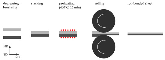
Figure 1.
Illustration of the bonding process with the rolling direction (RD), normal direction (ND), and transversal direction (TD).
Brushing was done as a single-step brush process and a two-step brush process with intermediate heating at 400 °C for 15 min. The stacked stripes were pre-heated at 400 °C for 15 min and immediately rolled afterwards at this temperature, since elevated rolling temperature can benefit the bonding strength, due to a greater surface expansion [25,59]. Furthermore, the higher temperature prevents the formation of deformation-induced martensite. Roll bonding was performed at a cold-rolling two-high reversing stand with roll diameters of 247 mm at a rolling speed of 0.2 m/s. The stacked sheets were rolled to a thickness of about 2 mm, which corresponds to a thickness reduction of approximately 50%. The roll-bonding process was performed for both mono-material stacks such as 7Ni-0.07C and 9Ni-0.04C as well for bi-material stacks composed of one 7Ni-0.07C sheet and one 9Ni-0.04C sheet.
2.2. Microstructural Investigations
Investigations on the microstructure at different states of the roll bonding process were performed using both optical microscopy and scanning electron microscopy (SEM) (MIRA 3, Tescan, Brno, Czech Republic). To investigate the microstructure at high resolution including grain size and texture SEM micrographs were taken using backscattered electron contrast (BSE) and electron backscattered diffraction (EBSD) measurements (TSL, Draper, UT, USA) were performed. For this purpose, SEM samples of TRIP and TWIP sheets were mechanically ground and finally vibration polished using a SiO2 suspension. SEM micrographs were also taken by secondary electron contrast (SE) to investigate the surface topography of the brushed and peeled sheet surfaces. Furthermore, energy-dispersive X-ray (EDX) microanalysis (EDAX/Ametek, Draper, UT, USA) was used to characterize the chemical composition on the peeled surface. In addition, optical micrographs were taken to characterize the brushed layer and the bonding zone. For this purpose, polished samples were etched with stain v2a additionally. Moreover, parameters such as mean roughness (Ra) and mean roughness depth (Rz) of the sheet surfaces after brushing were determined according to DIN EN ISO 25178-6 using a white light interferometer (Breitmeier Messtechnik GmbH, Ettlingen, Germany) to further characterize the surface topography.
2.3. Investigation of Hardness, Tensile Properties, and Peel Strength
Microhardness measurements (HV 0.1) were performed with a Vickers hardness tester (LECO Instrumente GmbH, Mönchengladbach, Germany) to estimate the hardness profile across the sheet thickness of hot-rolled and roll-bonded sheets. In addition, tensile tests were performed for both hot-rolled and roll-bonded conditions. Miniaturized tensile specimens according to Figure 2a were manufactured parallel to the rolling direction. The tensile tests were performed using a miniature load frame (Kammrath and Weiss GmbH, Dortmund, Germany) with a load capacity of 10 kN under displacement control and a motor velocity of 10 µm/s, which results in a quasistatic strain rate of 1.25 × 10⁻³ s−1. The macroscopic strain measurement was performed using a video extensometer (Chemnitzer Werkstoffmechanik GmbH, Chemnitz, Germany) based on digital image correlation. Moreover, the content of deformation-induced martensite in the specimens close to the fracture surface after the tensile tests were estimated with a Ferritescope (Helmut Fischer GmbH, Sindelfingen, Germany) according to Reference [60].
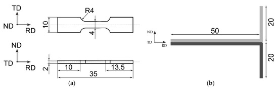
Figure 2.
Dimensions of the tensile and T-peel specimens. (a) Tensile specimens with a gauge length of about 8 mm and (b) peel sample with a width of 20 mm (bond width) (mm).
The bond strength was studied with the T-peel test according to ASTM-D1876-01 [61]. Figure 2b demonstrates the dimensions of the used T-peel specimen geometry. The T-peel tests were performed using a tensile testing machine with a load capacity of 50 kN at a crosshead speed of 1 mm/min. The maximum peel strength [15] or break-off peel strength [17], respectively, was estimated by the quotient of the maximum force divided by the bond width evaluated from the load vs. displacement curve according to Reference [17]:
maximum peel strength = (maximum force)/(bond width).
The average peel strength was estimated between the lowest and highest crosshead displacement with an almost constant average force, divided by the bond width [27,32]:
average peel strength = (average force)/(bond width).
According to Reference [49], the maximum peel strength corresponds to the necessary force for crack initiation in the bonding zone, while the average peel strength corresponds to the necessary force for crack growth propagation.
3. Results and Discussion
3.1. Microstructural Characterization
3.1.1. Hot-Rolled State
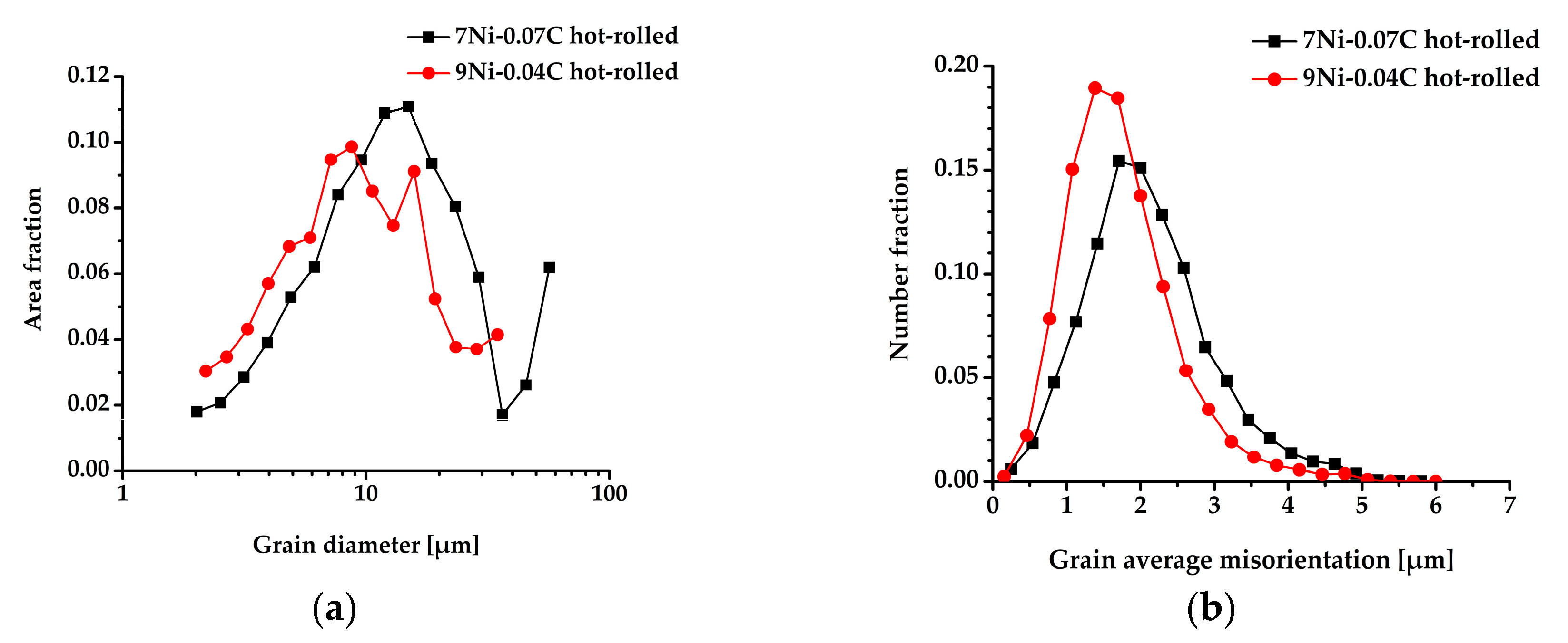
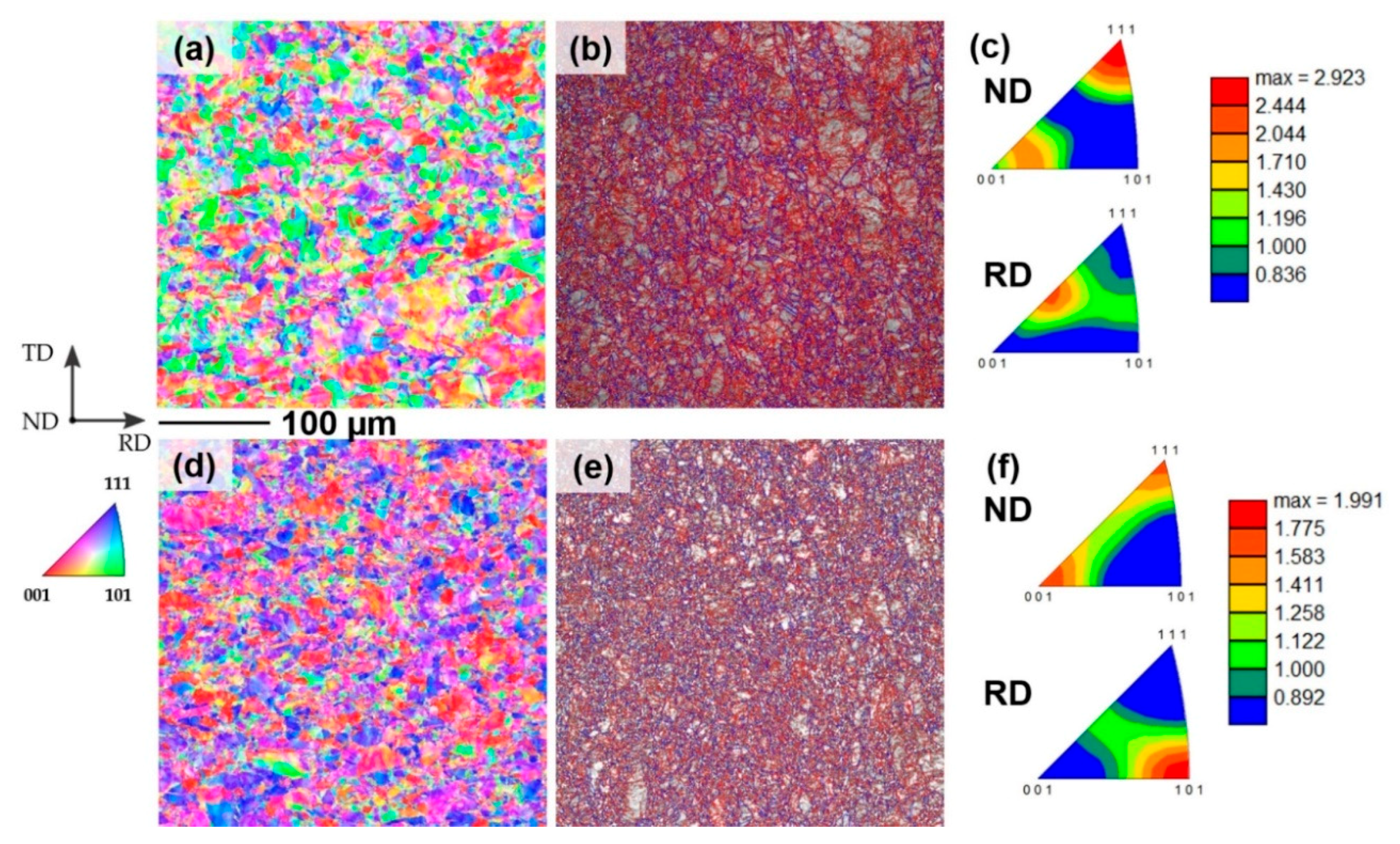
Figure 3 and Figure 4 summarize results of the microstructure of the hot-rolled states obtained by EBSD measurements including grain size distributions (Figure 3a), average grain mis-orientations (Figure 3b), crystallographic orientation maps (Figure 4a,d), grain boundary maps (Figure 4b,e), and texture (Figure 4c,f) for both steel variants.

Figure 3.
Distribution of grain sizes (a) and grain average misorientations (b) of 7Ni-0.07C (7%Ni) and 9Ni-0.04C (9%Ni) in the hot-rolled state.
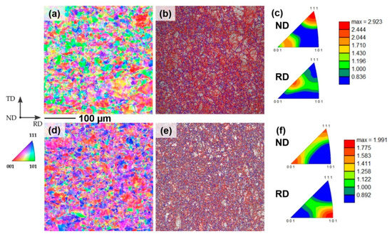
Figure 4.
Microstructure of the hot-rolled states of 7Ni-0.07C (a–c) and 9Ni-0.04C (d–f) obtained from EBSD measurements. (a,d) Crystallographic orientation maps. (b,e) Band contrast maps with large angle grain boundaries (blue) and small angle grain boundaries (red). (c,f) Texture in terms of inverse pole figures for normal (ND) and rolling directions (RD).
The microstructures of the as-cast states were characterized by a mean grain size of about 500 µm (7Ni-0.07C) and 1 mm (9Ni-0.04C), respectively. Hot rolling of both materials resulted in a significant reduction of the grain size. The mean grain sizes were determined to be about 16 µm (7Ni-0.07C) and 11 µm (9Ni-0.04C), respectively, using a misorientation angle between neighboring grains of 12°, as shown in Figure 3a. However, it already becomes obvious from the crystallographic orientation maps (Figure 4a,d) that the microstructures are not fully recrystallized. Thus, a high amount of small-angle grain boundaries (mis-orientation of 2 to 5°) given as red lines in Figure 4b,e was found in both microstructures. Furthermore, the average grain mis-orientation was calculated and is shown in Figure 3b. In this context, for both steels, a high amount of average grain mis-orientation was found, which is even slightly more pronounced for the 7Ni-0.07C. Moreover, both microstructures revealed only a very weak, but slightly different texture (Figure 4c,f) according to the dynamic recrystallization process and the different stacking fault energies (compare Table 1). Thus, the texture of 9Ni-0.04C is characterized by a pronounced cube orientation {001}<100>, pronounced rotated cube orientation {001}<110> and the component of the γ-fiber with {111}<110> parallel to the rolling plane and rolling direction. The texture of 7Ni-0.07C is characterized by cube orientation {001}<110> and {111}<112> component of the γ-fiber. From the macroscopical point of view, both materials exhibit a similar spreading behavior, which is beneficial for the roll-bonding process.
3.1.2. Brushed State
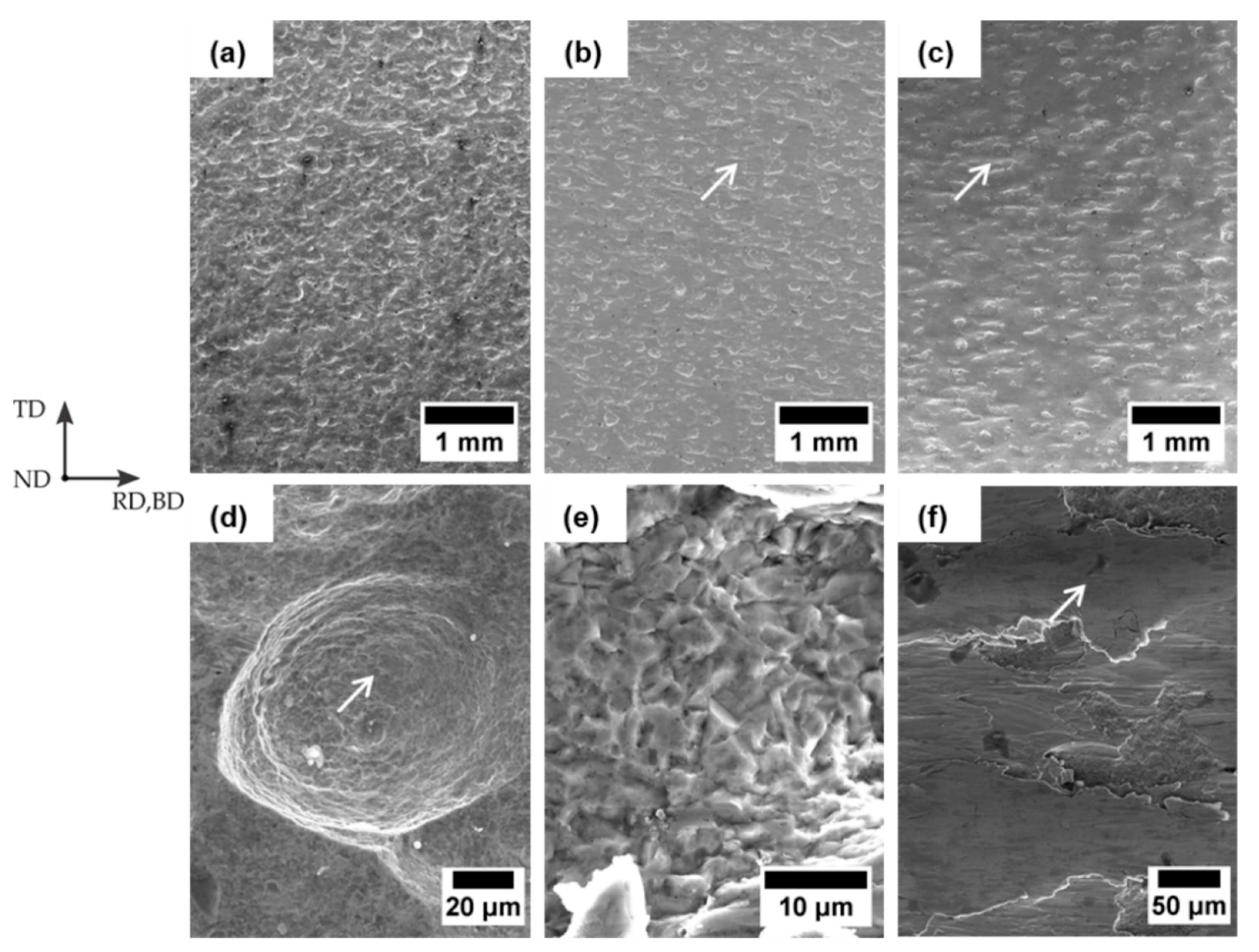
Figure 5 and Figure 6 illustrate the steel surfaces in the normal plane after hot rolling, after pickling, and after single as well as two-step brush process. The steel surfaces after hot rolling had a topographic nature with many grooves for both steels (Figure 5a,d (7Ni-0.07C) and Figure 6a,d (9Ni-0.04C)).
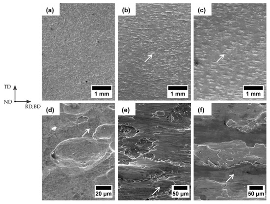
Figure 5.
SEM micrographics of 7Ni-0.07C steel surface in the normal plane after hot rolling and brushing. (a,d) Overview and close-up view of hot-rolled surface. (b,e) Overview and close-up of single step processed brush layer. (c,f) Overview and close-up view of two-step processed brush layer.

Figure 6.
SEM micrographics of 9Ni-0.04C steel surface in the normal plane after hot rolling and brushing. (a,d) Overview and close-up view of hot-rolled surface. (b,e) Overview and close-up of single step processed brush layer. (c,f) Overview and close-up view of two-step processed brush layer.
Furthermore, a pockmarked surface shape with microvoids the form of spherical “dimples” can be seen both in the grooves and outsides (Figure 5d and Figure 6d, marked with arrows), which are comparable to dimples on a ductile fracture surface [62].
The steel surfaces after single and two-step brushing process are shown in Figure 5b,c,e,f (7Ni-0.07C) and Figure 6b,c,e,f (9Ni-0.04C). They clarify an appearance of a brush layer, including plane areas and tongue-shaped risings (marked with arrows) both with scratches longitudinal in the brush direction (BD) as well as grooves remaining from the hot-rolled surface. A changed morphology of the grooves could be noticed according to Figure 6d,e. They demonstrate an appearance of smooth areas within the grooves namely indicating a brittle fracture surface [62]. Due to this brittle fracture surface, it can be concluded that besides the formation of a work-hardened brush layer [18,27], brushing ripped material out of the steel surface, such as reported in References [20,27,63], therefore, abrasive wear has occurred. Thus both the scratches and brittle fracture surfaces are signatures for abrasive wear [63,64]. This is in agreement with results reported in Reference [63]. A comparison between Figure 5b,c and Figure 6b,c demonstrates a higher proportion of groves after brushing for the steel 9Ni-0.04C than for the steel 7Ni-0.07C, which is attributed to the larger grooves after hot rolling (Figure 5d and Figure 6d). Moreover, pronounced tongue-shaped risings have been found after two-step brushing process, which can be clearly seen in Figure 5c and Figure 6c. This morphology of the created steel brush layer is comparable to that shown by Reference [14] and [20]. Thus, besides cooped areas [20], raised long tongue-shaped islands appear. Ref. [20] reports that the raised islands contain more contaminations than the cooped areas since an increase of oxygen in the raised islands was found in EDX measurements.
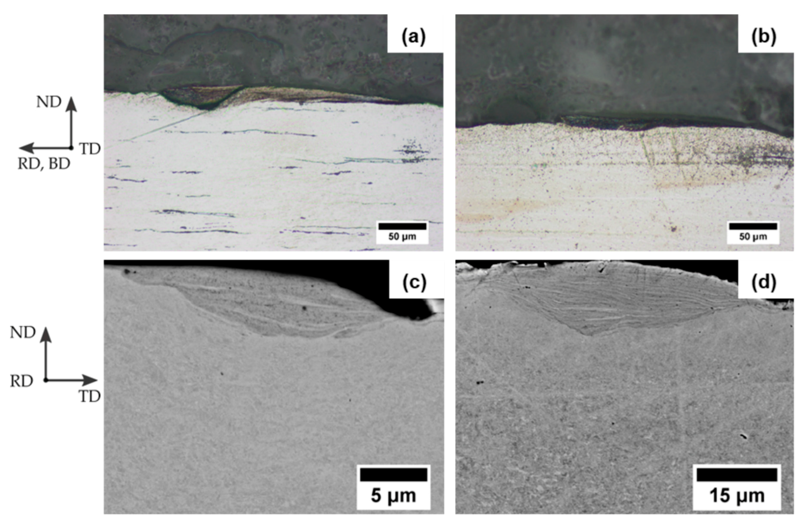
Optical micrographs and SEM micrographs of cross sections (Figure 7) illustrate the two-step processed brush layer in the longitudinal (ND-RD) and transversal (ND-TD) plane.

Figure 7.
Steel surface in the longitudinal and transversal plane after two-step brushing process. Optical micrographs of cover layer of 7Ni-0.07C (a) and 9Ni-0.04C (b) in the longitudinal plane. SEM micrographs of cover layer of 7Ni-0.07C (c) and 9Ni-0.04C (d) in the transversal plane.
Areas with a severely deformed microstructure, such as that reported in Reference [28], were found both in longitudinal and transversal plane for both steels. The shape of these deformed areas is either elongated parallel to the brush direction (BD) or lentil-like in longitudinal plane and transversal plane, respectively. These severely deformed areas exhibit a stronger etching attack and appear, therefore, in a darker contrast. Significantly higher amount of severely deformed areas were found after the two-step brush process compared to the single-step one, which corresponds to the pronounced appearance of risings after the two-step brush process (cf. Figure 5 and Figure 6). Additionally, a concentration of oxygen in this area was determined through EDX analyses. According to Bay [14], these areas created by the rotating brush wires consist of severely deformed base material together with oxides from the removed oxide layer and form a brittle work-hardened cover layer.
Based on the experimental results and literature it can be assumed, that tongue-shaped raised islands, risings respectively, illustrated in Figure 5 and Figure 6 and the darker area demonstrated in Figure 7, are both parts of the brittle worked hardened cover layer.
The topographic features observed by SEM micrographs on surfaces after different treatments (hot rolling, brushing) result in a higher surface roughness for both steels, which was quantitatively estimated using the white light interferometer. The results in terms of mean roughness Ra and mean roughness depth Rz are summarized in Table 2.
Table 2.
Surface roughness after hot rolling and brushing.
The roughness after hot rolling is attributed to a repeated break up of a pronounced oxide layer and penetration of the oxide pieces into the material during hot rolling by several passes, which led to the rough topography after removing the oxides trough pickling. In addition, a strong etching attack on the steel surface through the industrial pickling could also have contributed to the rough topography. Both determined average mean roughness (Ra) and mean roughness depth (Rz) from hot- rolled sheets of 9Ni-0.04C are higher than of 7Ni-0.07C. Hence, the grooves are larger and more pronounced in the case of 9Ni-0.04C, which caused the higher roughness. In this context, the lower Rz-values of 7Ni-0.07C can be attributed to a higher wear resistance due to a higher surface hardness and degree of work hardening, respectively, in comparison with 9Ni-0.04C.
According to Table 2, brushing caused a reduction of Ra and Rz on both steel surfaces due to friction and the formation of brush layer, respectively (Figure 5 and Figure 6). In this context, Rz and Ra values of steel 7Ni-0.07C surface are also lower than those of steel 9Ni-0.04C. This is also attributed to the more pronounced grooves on the 9Ni-0.04C surface, which remain after brushing. Furthermore, the estimated Rz and Ra-values were quite similar between single and two-step brushed steel surfaces.
3.1.3. Roll-Bonded State
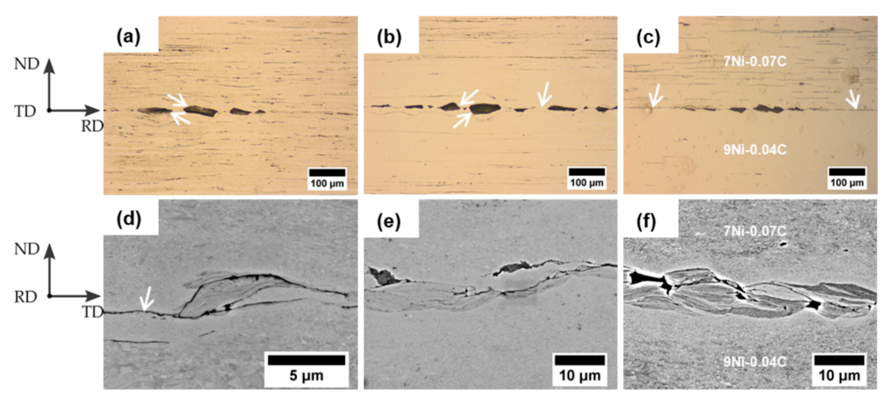
Figure 8 shows optical and SEM micrographs of the bonding zone of the roll-bonded mono materials and the composite sheet in the longitudinal and transversal plane. Micrographs of the bonding zone were similar between the roll-bonded sheets and show that the bonding zone includes in all cases in homogeneities such as oxides of the fractured brittle work-hardened cover layer. This bonding zone with oxides is similar to that presented in References [8,14,37,65]. Due to a different formability and higher hardness of the oxides in comparison to the steel, the steel has deformed around the oxides during deformation, as reported in Reference [37] (Figure 8a,c). In addition, Figure 8a,c illustrates a shear fracture under 45° of the brittle cover layer (marked with arrows) and their fragments are lying along a straight line, as reported in Reference [14]. Defects in the bonding zone are considered to affect the bonding strength [8,25,26,65,66,67]. Furthermore, partial separation between the layers is visible (Figure 8c,d, marked with arrows). Therefore, the majority of the bonding zone did not show a complete coalescence. Only a minor part of the bonding zone mostly between the fragments reveals a good interconnection of the material in the bonding zone [25] (Figure 8b, marked with an arrow). SEM micrographs (Figure 8d,f) show the bonding zone at higher magnification. Other defects, such as voids or cracks, are clearly visible. Voids can be attributed to the grooves after hot rolling, which remained after brushing (Figure 8e), as well as due to the fracture of the brittle cover layer (Figure 8f). Cracks were mostly found within the work-hardened cover layer (Figure 8e,f).
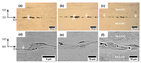
Figure 8.
Optical micrographs of the bonding zone in the longitudinal plane and SEM micrographs of the bonding zone in the transversal plane. (a) Optical micrograph of the 7Ni-0.07C bonding zone. (b) Optical micrograph of the 9Ni-0.04C bonding zone. (c) Optical micrograph of the composite bonding zone. (d) SEM micrographs of the 7Ni-0.07C bonding zone. (e) SEM micrographs of the 9Ni- 0.04C bonding zone. (f) SEM micrographs of the composite bonding zone.
Furthermore, a significantly smaller grain size is visible near the bonding zone compared to regions far from it (Figure 8f). It is due to the excessive shear in the bonding zone during roll bonding. This becomes even more obvious from EBSD measurements performed on the bi-material composite of steels 7Ni-0.07C and 9Ni-0.04C shown in Figure 9.
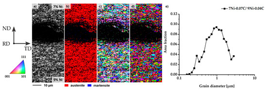
Figure 9.
Microstructure of the bonding zone of the bi-material laminate composite of steel 7Ni-0.07C and steel 9Ni-0.04C measured by EBSD. (a) Band contrast map. (b) Phase map. Red color: austenite; blue color: δ-ferrite or martensite. (c) Crystallographic orientation map. (d) Grain map. (e) Grain size distribution.
It demonstrates that the grain size has been significantly reduced by the roll bonding process. In this context, a mean grain size of about 1 µm evaluated over the whole AOI was estimated (Figure 9e). The area directly at the bonding zone including the area of the brittle cover layer was hardly measurable by EBSD. This is caused by both the high deformation degree in this region and the very small grain size. This non-indexed area (Figure 9a–d) has a dimension of about 20 µm in total across the bonding zone. The adjacent areas in both steel variants were characterized by a small grain size as well. Moreover, it becomes obvious that in these regions with a grain size of 1 µm, no martensitic phase transformation occurred (Figure 9b) due to the roll-bonding temperature of 400 °C.
3.2. Hardness Measurements and Tensile Properties
3.2.1. Hardness
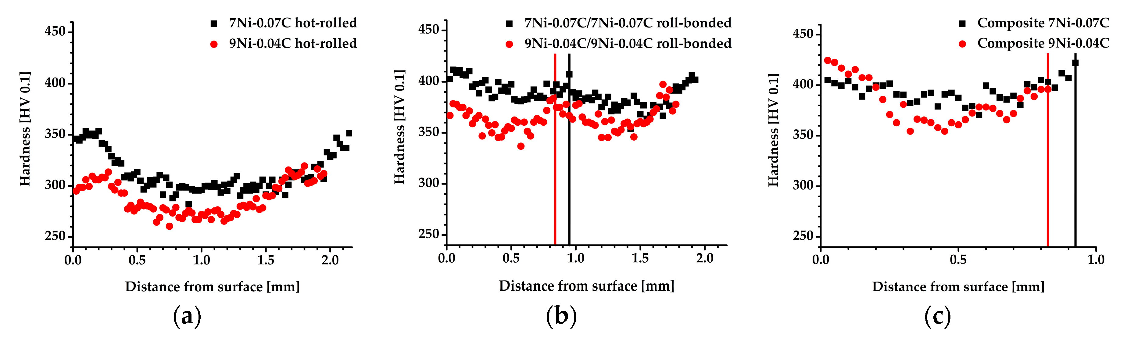
Figure 10 demonstrates the hardness profiles across the sheet thickness of the hot-rolled (Figure 10a) and roll-bonded sheets (Figure 10b,c).

Figure 10.
Hardness along the sheet thickness from the steel sheets both in hot-rolled (a) and plated state (b), (c) with vertical lines, which mark the location of the junction.
7Ni-0.07C shows a higher hardness in the hot-rolled state at each sheet location and also a higher hardness gradient between center and surface of the sheet than 9Ni-0.04C. The hardness gradient is due to the additional local shear strain through hot rolling [34,35] and an indication of an incomplete recrystallization, which explains the high hardness of more than 300 HV 0.1 after hot rolling. The higher hardness and hardness gradient of 7Ni-0.07C could be, like the smaller grooves after hot rolling (Section 3.1.2), attributed to a higher work hardening degree of 7Ni-0.07C in comparison with 9Ni-0.04C.
The hardness of the sheets increased after roll bonding due to the additional shear and compression strain. Also in this state, a higher hardness of 7Ni-0.07C was determined from the mono material sheets. Moreover, a parabolic hardness distribution profile along the sheet thickness was noticed. Hence, both the hardness at the surface and at the bonding zone of the sheet are higher than in the middle of the sheet with an equivalent distance to the bonding zone and the sheet surface. Besides the local higher shear strain in the surface and bonding zone, also the strain field around the oxide particles in the bonding zone (Figure 8) could have contributed to the higher local hardness [34]. A comparable hardness of the 9Ni-0.04C and 7Ni-0.07C sheets was estimated from the roll-bonded composite. This is attributed to a higher degree of deformation of the 9Ni-0.04C sheet in the composite after roll bonding due to the lower hardness after hot rolling in comparison with 7Ni-0.07C (Figure 10a), which resulted in a higher hardening degree, especially near the sheet surface (Figure 10c).
3.2.2. Tensile Properties
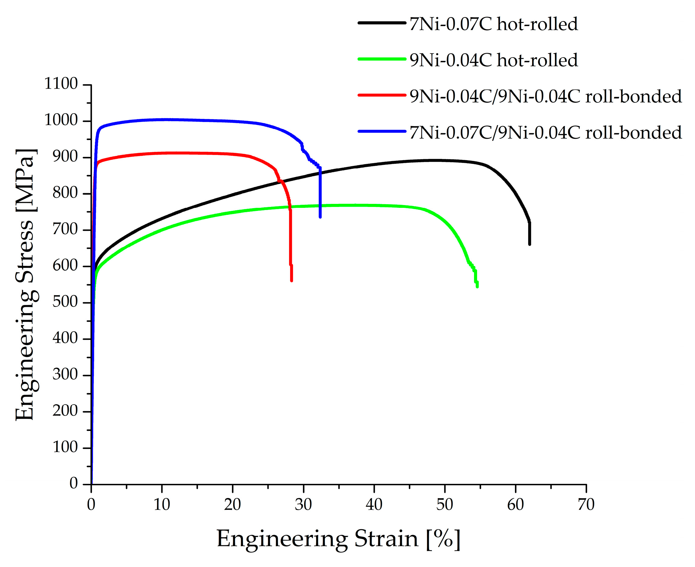
Figure 11 illustrates the engineering stress-engineering strain curves of the sheets in hot-rolled and roll-bonded conditions. In addition, the yield strength (Rp,0.2) and ultimate tensile strength (Rm) determined from the engineering stress-engineering strain curves and the content of strain induced martensite in the samples after the tensile tests are summarized in Table 3. Since a joining of the roll-bonded sheet of the 7Ni-0.07C material has not been achieved, and therefore, no tensile and peel samples could be prepared, there will be no results of mechanical properties from the 7Ni-0.07C roll- bonded sheet presented.

Figure 11.
Engineering stress-engineering strain curves for hot-rolled and roll-bonded steel specimens.
Table 3.
Yield strength and ultimate tensile strength of the hot-rolled and roll-bonded sheet as well as determined content of deformation induced martensite with specification of the standard deviation.
A deformation-induced martensite content of about 36 wt% was estimated after tensile test of the 7Ni-0.07C in hot-rolled state. Almost no martensite was estimated for the 9Ni-0.04C, both in hot- rolled and roll-bonded state (Table 3). It is well known that the TRIP-effect enforces a strong work hardening, resulting in a significant increase of ultimate tensile strength [1].
Hence, a higher work hardening degree of 7Ni-0.07C than 9Ni-0.04C can also be seen in Figure 11, resulting both in a higher Rm and elongation at break.
The yield strength of the roll-bonded mono material 9Ni-0.04C steel has increased significantly due to the work hardening and the small grain size. In addition, the strain to rupture is retained at a high level with approx. 20% of elongation in comparison to roll-bonded sheets of pure LC steel [33] or IF steel [38], which is caused by the TWIP effect. Furthermore, Figure 11 shows that the bi-material laminate composite reveals even higher yield strength and tensile strength at concurrently high ductility compared to the mono-material roll-bonded steel 9Ni-0.04C sheets due to the additional TRIP effect from the 7Ni-0.07C sheet, which resulted in a content of deformation-induced martensite of approximately 15 wt% (Table 3).
3.3. Bond Strength
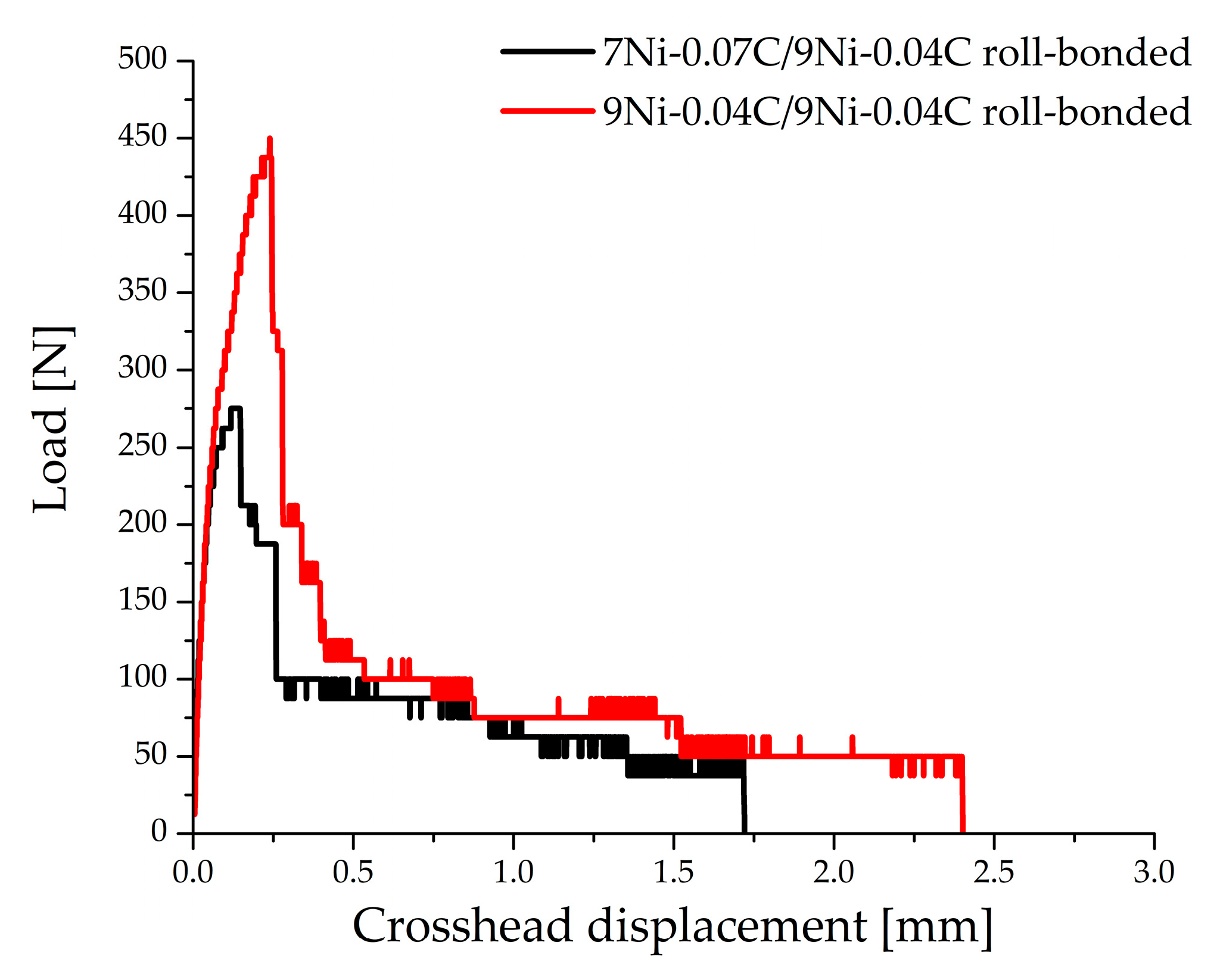
Figure 12 shows the load vs. displacement curves of the roll-bonded sheets from the T-peel tests. It can be seen that both the maximum and average peel strength from the 9Ni-0.04C/9Ni-0.04C roll-bonded sheet, which are illustrated in Table 4, are higher than from the 7Ni-0.07C/9Ni-0.04C roll-bonded composite. Hence, the maximum peel strength of the 9Ni-0.04C/9Ni-0.04C roll-bonded sheet is almost twice the maximum peel strength of the composite. Moreover, no joining of the roll-bonded 7Ni-0.07C/7Ni-0.07C sheet was achieved. The average force drops slightly with increasing crosshead displacement (Figure 12). According to Reference [17], this is attributed to a formation of a lever peel due to a smaller bond strength than the stiffness of the steels, which leads to a deviation of the crack tip away from the peel axis during crack propagation.
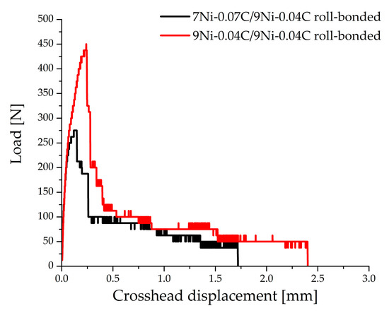
Figure 12.
Plot of load vs. displacement from the T-peel tests.
Table 4.
Maximum and average peel strength of the roll-bonded sheets.
To investigate the possible bonding mechanisms, SEM-micrographs of the peeled surface, which are illustrated in Figure 13, were taken.
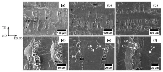
Figure 13.
SEM-micrographs of the peeled surface. (a,d) Overview and close-up view from mono material 9Ni-0.04C sheet. (b,e) Overview and close-up from composite 9Ni-0.04C sheet, including marked locations with determined nickel contents in wt%. (c,f) Overview and close-up from composite 7Ni-0.07C sheet, including marked locations with determined nickel contents in wt%. Peel direction (PD) is parallel to rolling direction (RD).
Figure 13 demonstrates that the brittle cover layer has broken up transversal to the rolling direction and fragments of the cover layer have accrued after the roll-bonding process. The obtained peeled steel surface has similarity with peeled steel surfaces, as reported in References [20] and [31]. Furthermore, “isolated islands” in form of circular-shape areas and ductile fracture surfaces were found mostly between the fragments of the cover layer. The fracture surfaces were circular shaped like the isolated islands but had also a sustained shape transversal to the peeling/rolling direction, that resembles the shape of a crack (Figure 13d,f). Both isolated islands and fracture surfaces were also found outside the fragments (Figure 13b). The ductile fracture surfaces prove that an adhesive bonding between the sheets has occurred. Additionally, they indicate the ductile fracture behavior of welded areas in roll-bonded metal sheets [14,15,18]. A higher amount of welding fracture surfaces was observed on the surface of peeled 9Ni-0.04C mono material sheets than on peeled surfaces from the composite, explaining the higher bond strength (Figure 12). Furthermore, a higher fraction of welding areas and isolated islands was observed on the 9Ni-0.04C surface than on the 7Ni-0.07C surface from the peeled composite sheets. EDX-analyses on the peeled surfaces of the composite indicated the existence of the 7Ni-0.07C materials in the isolated islands and welding areas on the 9Ni-0.04C surfaces and an existence of the 9Ni-0.04C-material in the isolated islands and welding areas on the 7Ni-0.07C material (Figure 13e,f). The identification of remained material from the opposite sheet corresponds to the results reported in Reference [26]. This may indicate that the delamination of the composite can start out both from the 9Ni-0.04C, as well as from the 7Ni-0.07C sheet.
Comprehensive reviews of the fundamentals of cold welding are published by Milner and Rowe [68] and Mohamed [69]. The most famous model of cold welding by roll bonding is the film theory introduced by Vaidynath [13], which was extended and modeled by Wright [18], Bay [14], Zhang [70], and Schmidtchen [49] to estimate the bond strength of roll-bonded sheets. According to Bay, the surface of the work-hardened brush layer consists of a brittle cover layer and a contaminated film layer of oxide and water. Adhesive bonding occurs only when the cover layer breaks up during deformation and virgin material extrudes out of the accrued cracks of the cover layer and comes in an interatomic distance with virgin material or a clean surface without contaminated film layer from the opposite steel surface. In this context, bonding also occurs between two surfaces without a cover layer. This is attributed to the vanishing of the contaminated film, through a local thinning during the deformation and leads to an absolutely clean contact surface, which is necessary for an adhesive bonding [11]. Besides adhesion also mechanical interlocking between surface asperities can contribute to the bond strength [20,25,30].
Based on the results and literature it can be assumed that virgin material has extruded through cracks of the brush layer, mostly out of cracks of cover layer, and can, therefore, be seen as isolated islands between the fragments of the cover layer. The amount of extruded material depends on the deformation degree, since much more isolated islands were found on the peeled surface on the 9Ni-0.04C sheet of the composite with a higher deformation (Figure 13b,c). When a pronounced adhesive bonding has formed, a welding area can occur after the peeling test. Adhesive bonding occurred very locally since only small areas of complete alignment in the bonding zones (Figure 8) and welding fracture surfaces on the peeled steel surfaces (Figure 13) were found.
There are different reasons why the bonding of 9Ni-0.04C material was much more pronounced than that of 7Ni-0.07C. The surface hardness of 9Ni-0.04C after hot rolling is lower (Figure 10), which promotes adhesion [71] and extrusion of virgin material through cracks [26,63,69,70], i.e., due to a higher formability. In this context, a lower degree of work hardening benefits the bonding either [28,63,69]. Furthermore, the formation of martensite in the brush layer in case 7Ni-0.07C trough brushing, which may deteriorate the bonding strength, and cannot be excluded either.
Further investigation should be accomplished to optimize the roll bonding process, such as exploring a more favorable surface preparation to increase the adhesion. In this context, accompanying simulations [49] will be carried out supporting the experimental procedures. The future results should contribute to the development of an ARB-process for laminated TRIP/TWIP steel composites.
4. Conclusions
In this work, sheets of high alloy TRIP and TWIP steels have been produced from cast plates through hot rolling. Roll-bonded sheets were produced afterwards through brushing, followed by cold rolling, and were micro-structurally, as well as mechanically, characterized. The investigation has shown that an adhesive bonding between mono 9Ni-0.04C (TWIP) material sheets as well as between a 9Ni-0.04C (TWIP) and a 7Ni-0.07C (TRIP) sheet was obtained after a thickness reduction of approximately 50%. Between two 7Ni-0.07C sheets no bonding was obtained. The bonding strength depends on the fraction of the welding area, which was higher in the roll-bonded mono 9Ni-0.04C material sheet. Besides the determined higher work hardening rate and hardness, a formation of martensite within the brush layer may also be detrimental for the roll bonding of 7Ni-0.07C sheets, indicating a lower suitability of TRIP-steels for roll bonding. The morphology and fraction of the brittle cover layer on the brush layer depends on the brushing conditions and was more pronounced after two-step brushing. Finally, outstanding strength with a high retained formability of the roll- bonded composite sheet was revealed by tensile tests due to the formation of deformation induced martensite.
Author Contributions
M.S., A.W. and Y.Q. conceived and designed the experiments. N.K. and Y.Q. performed the experiments. A.W. and Y.Q. analyzed the data. Y.Q. wrote the paper. H.B., U.P. and A.W. supervised all investigations and revised the paper.
Funding
This research was funded by DEUTSCHE FORSCHUNGSGEMEINSCHAFT, Collaborative Research Center TRIP-Matrix-Composites (CRC 799).
Acknowledgments
The authors acknowledge gratefully the funding of the DEUTSCHE FORSCHUNGSGEMEINSCHAFT for the financial support of the postdoc project, which is associated with the Collaborative Research Center TRIP-Matrix-Composites (CRC 799). Moreover, the authors would like to especially thank Klaus König from Institute of Electronic and Sensor Materials for manufacturing of specimens. Both Katrin Becker from Institute of Materials Science and Robby Prang from Institute of Materials Engineering are very much acknowledged for preparation of samples. The authors appreciate also their greatest thanks to Uwe Heinze from Institute of Metal Forming for executions of hot rolling and roll bonding. Furthermore, special thanks go to Thilo Kreschel from the Institute of Iron and Steel technology for chemical analyses of the investigated materials.
Conflicts of Interest
The authors declare no conflict of interest.
References
- Cheng, X.; Petrov, R.; Zhao, L.; Janssen, M. Fatigue crack growth in TRIP steel under positive R-ratios. Eng. Fract. Mech. 2008, 75, 739–749. [Google Scholar] [CrossRef]
- Martin, S.; Wolf, S.; Decker, S.; Krüger, L.; Martin, U. Deformation Bands in High-Alloy Austenitic 16Cr6Mn6Ni TRIP Steel: Phase Transformation and Its Consequences on Strain Hardening at Room Temperature. Steel Res. Int. 2015, 86, 1187–1196. [Google Scholar] [CrossRef]
- Kalidindi, S.R. Modeling the strain hardening response of low SFE FCC alloys. Int. J. Plast. 1998, 14, 1265–1277. [Google Scholar] [CrossRef]
- Gutierrez-Urrutia, I.; Raabe, D. Grain size effect on strain hardening in twinning-induced plasticity steels. Scr. Mater. 2012, 66, 992–996. [Google Scholar] [CrossRef]
- Biermann, H.; Glage, A.; Droste, M. Influence of Temperature on Fatigue-Induced Martensitic Phase Transformation in a Metastable CrMnNi-Steel. Metall. Mater. Trans. A 2016, 47, 84–94. [Google Scholar] [CrossRef]
- Martin, S.; Fabrichnaya, O.; Rafaja, D. Prediction of the local deformation mechanisms in metastable austenitic steels from the local concentration of the main alloying elements. Mater. Lett. 2015, 159, 484–488. [Google Scholar] [CrossRef]
- Sardar, S.; Mandal, A.; Pal, S.K.; Singh, S.B. Solid-State Joining by Roll Bonding and Accumulative Roll Bonding. In Advances in Material Forming and Joining; Narayanan, R.G., Dixit, U.S., Eds.; Springer: New Delhi, India, 2015; pp. 351–377. [Google Scholar]
- Saito, Y.; Utsunomiya, H.; Tsuji, N.; Sakai, T. Novel ultra-high straining process for bulk materials—Development of the accumulative roll-bonding (ARB) process. Acta Mater. 1999, 47, 579–583. [Google Scholar] [CrossRef]
- Azushima, A.; Kopp, R.; Korhonen, A.; Yang, D.Y.; Micari, F.; Lahoti, G.D.; Groche, P.; Yanagimoto, J.; Tsuji, N.; Rosochowski, A.; et al. Severe plastic deformation (SPD) processes for metals. CIRP Ann. 2008, 57, 716–735. [Google Scholar] [CrossRef]
- Jamaati, R.; Toroghinejad, M.R.; Amirkhanlou, S.; Edris, H. On the Achievement of Nanostructured Interstitial Free Steel by Four-Layer Accumulative Roll Bonding Process at Room Temperature. Metall. Mater. Trans. A 2015, 46, 4013–4019. [Google Scholar] [CrossRef]
- Krallics, G.; Lenard, J.G. An examination of the accumulative roll-bonding process. J. Mater. Process. Technol. 2004, 152, 154–161. [Google Scholar] [CrossRef]
- Tsuji, N.; Kamikawa, N.; Ueji, R.; Takata, N.; Koyama, H.; Terada, D. Managing Both Strength and Ductility in Ultrafine Grained Steels. ISIJ Int. 2008, 48, 1114–1121. [Google Scholar] [CrossRef]
- Vaidyanath, L.R.; Nicholas, M.G.; Milner, D.R. Pressure welding by rolling. Br. Weld. J. 1959, 6, 13–28. [Google Scholar]
- Bay, N. Mechanism Producing Metallic Bonds in Cold Welding: Scanning electron microscope investigation shows two coalescence mechanisms are involved in the cold welding of aluminum to aluminum. Weld. J. 1983, 62, 137–142. [Google Scholar]
- Madaah-Hosseini, H.R.; Kokabi, A.H. Cold roll bonding of 5754-aluminum strips. Mater. Sci. Eng. A 2002, 335, 186–190. [Google Scholar] [CrossRef]
- Reichelt, S.; Saleh, H.; Schmidtchen, M.; Kawalla, R. On the Bonding Strength of Mg-Mg and Mg-Al Material Compounds. Mater. Sci. Forum 2014, 783–786, 455–460. [Google Scholar] [CrossRef]
- Chen, C.-Y.; Chen, H.-L.; Hwang, W.-S. Influence of Interfacial Structure Development on the Fracture Mechanism and Bond Strength of Aluminum/Copper Bimetal Plate. Mater. Trans. 2006, 47, 1232–1239. [Google Scholar] [CrossRef]
- Wright, P.K.; Snow, D.A.; Tay, C.K. Interfacial conditions and bond strength in cold pressure welding by rolling. Met. Technol. 1978, 24, 24–31. [Google Scholar] [CrossRef]
- Akramifard, H.R.; Mirzadeh, H.; Parsa, M.H. Cladding of aluminum on AISI 304L stainless steel by cold roll bonding: Mechanism, microstructure, and mechanical properties. Mater. Sci. Eng. A 2014, 613, 232–239. [Google Scholar] [CrossRef]
- Gao, C.; Li, L.; Chen, X.; Zhou, D.; Tang, C. The effect of surface preparation on the bond strength of Al-St strips in CRB process. Mater. Des. 2016, 107, 205–211. [Google Scholar] [CrossRef]
- Jindal, V.; Srivastava, V.C. Growth of intermetallic layer at roll bonded IF-steel/aluminum interface. J. Mater. Process. Technol. 2008, 195, 88–93. [Google Scholar] [CrossRef]
- Kümmel, F.; Diepold, B.; Sauer, K.F.; Schunk, C.; Prakash, A.; Höppel, H.W.; Göken, M. High Lightweight Potential of Ultrafine-Grained Aluminum/Steel Laminated Metal Composites Produced by Accumulative Roll Bonding. Adv. Eng. Mater. 2018, 6. [Google Scholar] [CrossRef]
- Movahedi, M.; Kokabi, A.H.; Seyed Reihani, S.M. Investigation on the bond strength of Al-1100/St-12 roll bonded sheets, optimization and characterization. Mater. Des. 2011, 32, 3143–3149. [Google Scholar] [CrossRef]
- Akdesir, M.; Zhou, D.; Foadian, F.; Palkow, H. Study of Different Surface Pre-treatment Methods on Bonding Strength of Multilayer Aluminium Alloys/Steel Clad Material. Int. J. Eng. Res. Sci. 2016, 2, 169–177. [Google Scholar]
- Buchner, M.; Buchner, B.; Buchmayr, B.; Kilian, H.; Riemelmoser, F. Investigation of different parameters on roll bonding quality of aluminium and steel sheets. Int. J. Mater. Form. 2008, 1, 1279–1282. [Google Scholar] [CrossRef]
- Soltan Ali Nezhad, M.; Haerian Ardakani, A. A study of joint quality of aluminum and low carbon steel strips by warm rolling. Mater. Des. 2009, 30, 1103–1109. [Google Scholar] [CrossRef]
- Manesh, H.D.; Taheri, A.K. Study of mechanisms of cold roll welding of aluminium alloy to steel strip. Mater. Sci. Technol. 2004, 20, 1064–1068. [Google Scholar] [CrossRef]
- Wang, C.; Jiang, Y.; Xie, J.; Zhou, D.; Zhang, X. Effect of the steel sheet surface hardening state on interfacial bonding strength of embedded aluminum–steel composite sheet produced by cold roll bonding process. Mater. Sci. Eng. A 2016, 652, 51–58. [Google Scholar] [CrossRef]
- Wang, C.; Jiang, Y.; Xie, J.; Zhou, D.; Zhang, X. Interface formation and bonding mechanism of embedded aluminum-steel composite sheet during cold roll bonding. Mater. Sci. Eng. A 2017, 708, 50–59. [Google Scholar] [CrossRef]
- Tang, C.; Liu, Z.; Zhou, D.; Wu, S. Surface Treatment with the Cold Roll Bonding Process for an Aluminum Alloy and Mild Steel. Strength Mater. 2015, 47, 150–155. [Google Scholar] [CrossRef]
- Yang, X.; Weng, H.; Tang, C.-L. Interfacial Bonding Mechanism of Aluminum and Steel Composites. Adv. Compos. Lett. 2018, 27, 71–76. [Google Scholar]
- Jamaati, R.; Toroghinejad, M.R.; Edris, H. Comparison of Microparticles and Nanoparticles Effects on the Bonding of Roll Bonded IF Steel. Trans. Indian Inst. Met. 2014, 67, 659–665. [Google Scholar] [CrossRef]
- Kubina, T.; Gubiš, J. Potential for obtaining an ultrafine microstructure of low-carbon steel using accumulative roll bonding. Mater. Technol. 2015, 49, 521–525. [Google Scholar] [CrossRef]
- Costa, A.L.M.; Reis, A.C.C.; Kestens, L.; Andrade, M.S. Ultra grain refinement and hardening of IF-steel during accumulative roll-bonding. Mater. Sci. Eng. A 2005, 406, 279–285. [Google Scholar] [CrossRef]
- Kamikawa, N.; Sakai, T.; Tsuji, N. Effect of redundant shear strain on microstructure and texture evolution during accumulative roll-bonding in ultralow carbon IF steel. Acta Mater. 2007, 55, 5873–5888. [Google Scholar] [CrossRef]
- Kamikawa, N.; Tsuji, N.; Minamino, Y. Microstructure and texture through thickness of ultralow carbon IF steel sheet severely deformed by accumulative roll-bonding. Sci. Technol. Adv. Mater. 2016, 5, 163–172. [Google Scholar] [CrossRef]
- Hagemann, P.; Schmidtchen, M.; Rafaja, D.; Kawalla, R. Investigation of production technologies for sub-microcrystalline materials with a special emphasis on accumulative roll bonding (ARB). Steel Res. Int. 2011, 82, 713–718. [Google Scholar]
- Cruz-Gandarilla, F.; Salcedo-Garrido, A.M.; Bolmaro, R.E.; Baudin, T.; de Vincentis, N.S.; Avalos, M.; Cabañas-Moreno, J.G.; Mendoza-Leon, H. Microstructural evolution and mechanical properties on an ARB processed IF steel studied by X-ray diffraction and EBSD. Mater. Charact. 2016, 118, 332–339. [Google Scholar] [CrossRef]
- Cruz-Gandarilla, F.; Salcedo-Garrido, A.M.; Avalos, M.; Bolmaro, R.; Baudin, T.; Cabañas-Moreno, J.G.; Dorantes-Rosales, H.J. EBSD characterization of an IF steel processed by Accumulative Roll Bonding. IOP Conf. Ser. Mater. Sci. Eng. 2015, 82, 12077. [Google Scholar] [CrossRef]
- Kaya, Y.; Kahraman, N. An investigation into the explosive welding/cladding of Grade A ship steel/AISI 316L austenitic stainless steel. Mater. Des. 2013, 52, 367–372. [Google Scholar] [CrossRef]
- Zhao, G.; Li, Y.; Li, J.; Huang, Q.; Ma, L. Experimental analysis of two-layered dissimilar metals by roll bonding. Mater. Res. Express 2018, 5. [Google Scholar] [CrossRef]
- Dhib, Z.; Guermazi, N.; Ktari, A.; Gasperini, M.; Haddar, N. Mechanical bonding properties and interfacial morphologies of austenitic stainless steel clad plates. Mater. Sci. Eng. A 2017, 696, 374–386. [Google Scholar] [CrossRef]
- Bouaziz, O.; Masse, J.P.; Petitgand, G.; Huang, M.X. A Novel Strong and Ductile TWIP/Martensite Steel Composite. Adv. Eng. Mater. 2016, 18, 56–59. [Google Scholar] [CrossRef]
- Park, J.; Kim, J.-S.; Kang, M.; Sohn, S.S.; Cho, W.T.; Kim, H.S.; Lee, S. Tensile property improvement of TWIP-cored three-layer steel sheets fabricated by hot-roll-bonding with low-carbon steel or interstitial-free steel. Sci. Rep. 2017, 7, 40231. [Google Scholar] [CrossRef] [PubMed]
- Park, J.; Kang, M.; Sohn, S.S.; Kim, J.-S.; Kim, H.S.; Cho, W.T.; Lee, S. Tensile properties of cold-rolled TWIP-cored three-layer steel sheets. Mater. Sci. Eng. A 2017, 686, 160–167. [Google Scholar] [CrossRef]
- Jafarian, H. Characteristics of nano/ultrafine-grained austenitic TRIP steel fabricated by accumulative roll bonding and subsequent annealing. Mater. Charact. 2016, 114, 88–96. [Google Scholar] [CrossRef]
- Jafarian, H.R.; Anijdan, S.M.; Eivani, A.R.; Park, N. A comprehensive study of microstructure development and its corresponding tensile properties in nano/ultrafine-grained metastable austenitic steel during accumulative roll bonding (ARB). Mater. Sci. Eng. A 2017, 703, 196–204. [Google Scholar] [CrossRef]
- Li, L.; Nagai, K.; Yin, F. Progress in cold roll bonding of metals. Sci. Technol. Adv. Mater. 2008, 9. [Google Scholar] [CrossRef] [PubMed]
- Schmidtchen, M. Mehrskalige Modellierung des Walzplattierens und Walzens von Werkstoffverbunden; Technische Universität Bergakademie Freiberg: Freiberg, Germany, 2017; ISBN 978-3-86012-566-3. (In German) [Google Scholar]
- Martin, S.; Wolf, S.; Martin, U.; Krüger, L.; Rafaja, D. Deformation Mechanisms in Austenitic TRIP/TWIP Steel as a Function of Temperature. Metall. Mater. Trans. A 2016, 47, 49–58. [Google Scholar] [CrossRef]
- Ackermann, S.; Martin, S.; Schwarz, M.R.; Schimpf, C.; Kulawinski, D.; Lathe, C.; Henkel, S.; Rafaja, D.; Biermann, H.; Weidner, A. Investigation of Phase Transformations in High-Alloy Austenitic TRIP Steel Under High Pressure (up to 18 GPa) by In Situ Synchrotron X-ray Diffraction and Scanning Electron Microscopy. Metall. Mater. Trans. A 2016, 47, 95–111. [Google Scholar] [CrossRef]
- Eckner, R.; Krüger, L.; Motylenko, M.; Savinykh, A.S.; Razorenov, S.V.; Garkushin, G.V.; Buzaud, E.; Cosculluela, A.; Couque, H.; Cadoni, E. Deformation mechanisms and microplasticity of austenitic TRIP/TWIP steel under flyer plate impact. EPJ Web Conf. 2018, 183. [Google Scholar] [CrossRef]
- Droste, M.; Ullrich, C.; Motylenko, M.; Fleischer, M.; Weidner, A.; Freudenberger, J.; Rafaja, D.; Biermann, H. Fatigue behavior of an ultrafine-grained metastable CrMnNi steel tested under total strain control. Int. J. Fatigue 2018, 106, 143–152. [Google Scholar] [CrossRef]
- Weidner, A.; Müller, A.; Weiss, A.; Biermann, H. Ultrafine grained high-alloyed austenitic TRIP steel. Mater. Sci. Eng. A 2013, 571, 68–76. [Google Scholar] [CrossRef]
- Weiß, A.; Gutte, H.; Jahn, A.; Scheller, P.R. Nichtrostende Stähle mit TRIP/TWIP/SBIP-Effekt. Mater. Sci. Eng. Technol. 2009, 40, 606–611. [Google Scholar] [CrossRef]
- Dai, Q.-X.; Wang, A.-D.; Cheng, X.-N.; Luo, X.-M. Stacking fault energy of cryogenic austenitic steels. Chin. Phys. 2002, 11, 596–600. [Google Scholar]
- Jahn, A.; Kovalev, A.; Weiß, A.; Scheller, P.R. Influence of Manganese and Nickel on the α´ Martensite Transformation Temperatures of High Alloyed Cr-Mn-Ni Steels. Steel Res. Int. 2011, 82, 1108–1112. [Google Scholar] [CrossRef]
- Jahn, A.; Kovalev, A.; Weiß, A.; Wolf, S.; Krüger, L.; Scheller, P.R. Temperature Depending Influence of the Martensite Formation on the Mechanical Properties of High-Alloyed Cr-Mn-Ni As-Cast Steels. Steel Res. Int. 2011, 82, 39–44. [Google Scholar] [CrossRef]
- Jamaati, R.; Toroghinejad, M.R. Cold roll bonding bond strengths: Review. Mater. Sci. Technol. 2013, 27, 1101–1108. [Google Scholar] [CrossRef]
- Talonen, J.; Aspegren, P.; Hänninen, H. Comparison of different methods for measuring strain induced α-martensite content in austenitic steels. Mater. Sci. Technol. 2013, 20, 1506–1512. [Google Scholar] [CrossRef]
- D14 Committee. Test Method for Peel Resistance of Adhesives (T-Peel Test); ASTM International: West Conshohocken, PA, USA, 2015. [Google Scholar]
- Wainstein, D.; Kovalev, A. Design Simulation of Kinetics of Multicomponent Grain Boundary Segregations in the Engineering Steels Under Quenching and Tempering. In Modeling and Simulation for Material Selection and Mechanical Design; Totten, G., Xie, L., Funatani, K., Eds.; CRC Press: Boca Raton, FL, USA, 2003. [Google Scholar]
- Bagheri, A.; Toroghinejad, M.R.; Taherizadeh, A. Effect of Roughness and Surface Hardening on the Mechanical Properties of Three-Layered Brass/IF Steel/Brass Composite. Trans. Indian Inst. Met. 2018, 24, 617. [Google Scholar] [CrossRef]
- Du, Y.; Zhang, P.; Zhang, J.; Yao, S. Radial Distribution of SiC Particles in Mechanical Stirring of A356–SiCp Liquid. J. Mater. Sci. Technol. 2012, 28, 951–955. [Google Scholar] [CrossRef]
- Tohidi, A.A.; Ketabchi, M.; Hasannia, A. Nanograined Ti–Nb microalloy steel achieved by Accumulative Roll Bonding (ARB) process. Mater. Sci. Eng. A 2013, 577, 43–47. [Google Scholar] [CrossRef]
- Springer, H.; Tasan, C.; Raabe, D. A novel roll-bonding methodology for the cross-scale analysis of phase properties and interactions in multiphase structural materials. Int. J. Mater. Res. 2015, 106, 3–14. [Google Scholar] [CrossRef]
- Jin, H.R.; Zhang, L.; Dai, C.; Yi, Y.L. Numerical Simulation and Experimental Study on the Interface Bonding of Stainless Steel Clad Plate. Strength Mater. 2018, 50, 29–40. [Google Scholar] [CrossRef]
- Milner, D.R.; Rowe, G.W. Fundamentals of Solid-Phase Welding. Metall. Rev. 1962, 7, 433–480. [Google Scholar] [CrossRef]
- Mohamed, H.A.; Washburn, J. Mechanism of Solid State Pressure Welding. Weld. J. 1975, 54, 302–310. [Google Scholar]
- Zhang, W.; Bay, N. A Numerical Model for Cold Welding of Metals. CIRP Ann. 1996, 45, 215–220. [Google Scholar] [CrossRef]
- Gilbreath, W.P.; Sumsion, H.T. Solid-phase welding of metals under high vacuum. J. Spacecraft Rockets 1966, 3, 674–679. [Google Scholar] [CrossRef]


© 2019 by the authors. Licensee MDPI, Basel, Switzerland. This article is an open access article distributed under the terms and conditions of the Creative Commons Attribution (CC BY) license (http://creativecommons.org/licenses/by/4.0/).