Article

Sensitivity Analysis of Tool Wear in Drilling of Titanium Aluminides

by
Aitor Beranoagirre
1,*,
Gorka Urbikain
1,*,
Raúl Marticorena
2,
Andrés Bustillo
2 and
Luis Norberto López de Lacalle
3
1
Department of Mechanical Engineering, University of the Basque Country (UPV/EHU), Plaza Europa 1, 20018 San Sebastián, Spain
2
Department of Civil Engineering, Universidad de Burgos, Avda Cantabria s/n, 09006 Burgos, Spain
3
CFAA, University of the Basque Country (UPV/EHU), Parque Tecnológico de Zamudio 202, 48170 Bilbao, Spain
*
Authors to whom correspondence should be addressed.
Metals 2019, 9(3), 297; https://doi.org/10.3390/met9030297
Submission received: 6 February 2019 / Revised: 21 February 2019 / Accepted: 27 February 2019 / Published: 6 March 2019

Abstract

:
In the aerospace industry, a large number of holes need to be drilled to mechanically connect the components of aircraft engines. The working conditions for such components demand a good response of their mechanical properties at high temperatures. The new gamma TiAl are in the transition between the 2nd and 3rd generation, and several applications are proposed for that sector. Thus, NASA is proposing the use of the alloys in the Revolutionary Turbine Accelerator/Turbine-Based Combined Cycle (RTA/TBCC) Program for the next-generation launch vehicle, with gamma TiAl as a potential compressor and structural material. However, the information and datasets available regarding cutting performance in titanium aluminides are relatively scarce. So, a considerable part of the current research efforts in this field is dedicated to process optimization of cutting parameters and tool geometries. The present work is framed in the study of wear when machining holes in these difficult-to-cut alloys. In particular, the work presents the results from drilling tests on three types of gamma TiAl alloys, extruded MoCuSi, ingot MoCuSi, and TNB type, to define an optimal set of cutting parameters. Maintaining uniform, gradual wear is key to avoiding tool breakage and enabling good hole dimensional accuracy. So, this paper proposes a model based on ANOVA analysis to identify the relationships between cutting conditions and resulting wear and estimate tool life. The best cutting parameters were found at vc = 10–15 m/min and fn = 0.025 mm/rev.

1. Introduction

The aerospace industry is a key area in advanced materials research. The increasing temperatures in aircraft engines lead to the use of new materials with higher capabilities, especially titanium alloys and nickel-based superalloys [1]. Titanium alloys are often selected for the plane fuselage (10% in weight) to prevent crack growth as in motor parts (35–40%), followed by nickel-based superalloys (40%), but with a higher volume percentage. The focus here is on titanium aluminides, also called γ-TiAl alloys or intermetallic alloys.
The development of TiAl alloys started in 1950 but industrial interest continues to grow [2]. Indeed, some parts of the turbine engine could be manufactured out of γ-TiAl instead of nickel superalloys (Inconel 718) and conventional titanium alloys (such as Ti64). The new gamma TiAl are in transition between the 2nd and 3rd generation, with several applications proposed for the latter. Thus, NASA [3] is proposing the use of the alloys in the Revolutionary Turbine Accelerator/Turbine-Based Combined Cycle (RTA/TBCC) Program for the next-generation launch vehicle, with gamma TiAl as a potential compressor and structural material. The problem with manufacturing real parts is the post-processing required to achieve the tight tolerances defined in the blueprints, because alloy fragility and rapid tool wear are two key problems. An experimental campaign was the only way to achieve data sound enough to work in real applications [4]. The difference between γ-TiAl alloys and other alloys such as Ti6Al4V lies in the aluminum percentage, 43–48% in γ-TiAl to 6% in Ti6Al4V, which highly improves the thermal conductivity in γ-TiAl but reduces the ductile transition temperature, which occurs in the range 600–800 °C.
Specifically, hole making in this kind of piece is a critical step during the manufacturing process [5] due to the close tolerances imposed and considering the accumulated added value before this stage.
The available literature referring to titanium-based alloys is quite extensive. However, the underlying physical‒chemical phenomena need to be further investigated. Over the last few decades, an important increase in productivity has been observed [6]. A great effort was made to increase the mass removal rate (MRR), with higher cutting speeds and feed rates [7,8]. Some authors focused on the chip formation process. Komanduri and von Turkovich [9] explained the serrated chip morphology using the thermoplastic shear model. A second theory states that chip generation is due to a periodic crack initialization over the primary zone because of the high stress levels [10]. Many authors studied the metallurgical microstructure of the chip by X-ray diffraction and SEM [11,12]. Tool wear is another subject of concern. Some authors found that wear mechanisms are also very dependent on the cutting tool materials [13]. Hartung et al. [14] gave a complete picture of wear in titanium alloys. Nouari et al. [15] studied the influence of the cutting parameters and tool geometry over the wear phenomena, stating the importance of an adequate characterization of the temperature, pressure and contact length. They used FE modeling to predict the temperature, recognized as a key parameter in controlling tool wear. More recently, Bermingham et al. [16] studied the effect of cryogenic techniques on tool life in titanium alloy Ti6Al4V. They found that the greatest improvement in tool life using a cryogenic coolant occurs for high feed rates combined with low depths of cut. Polvorosa et al. [17] studied wear mechanisms in nickel-based alloys and discussed the effect of using different coolant pressures. Beranoagirre et al. discussed the machinability of gamma TiAl in EDM [18] and in drilling processes [19], where a mechanistic model was proposed for cutting force and torque prediction. Regarding soft titanium alloys, Kuczmaszewski et al. [20] demonstrated that ultra-fine-grain SC milling cutters are the tools most resistant to chipping while leaving a good surface finish. Jozwik et al. analyzed the tribological properties of Ti6Al4V [21] and the effects of the technological parameters of the selective laser melting (SLM) process on the morphological properties of the manufactured surfaces [22].
Uddin et al. [23] evaluated the influence of the key process parameters on drilling performance when using high-speed steel (HSS) bits. They studied the process mechanics in terms of dimensional accuracy, burr formation, surface finish, etc. Some authors used ANOVA analyses and multi-objective optimization to find optimum drilling parameters using response surface analyses in aluminum [24] and titanium alloys [25].
Although the existing research sheds some light on the effect of different cutting parameters of machining holes in gamma TiAl alloys, two main aspects are still to be clarified. First, these analyses consider only one kind of gamma TiAl alloy in each case; second, the study of the wear process of drilling of these alloys is a very expensive task because it requires the waste of many cutting tools over their whole lifetime to test different cutting conditions, and the destruction of large amounts of expensive workpieces that are systematically drilled. Collaboration with industries will not easily solve this restriction because they may not be open to testing many different drilling conditions or allow testing on real workpieces up to the tool’s breakage limit. Therefore, the identification of the best cutting conditions with a very limited number of different experimental tests is a must for wear analysis of gamma TiAl alloys.
The present work is framed in the study of wear when machining holes in gamma TiAl. In particular, the work presents the results from drilling tests on three types of gamma TiAl, TNB-type, extruded MoCuSi, and ingot MoCuSi, to define an optimal set of cutting parameters. The paper proposes a comprehensible model to identify the relationships between cutting conditions and resulting wear that is useful to estimate tool life and to save part tolerances.
In this work ANalysis Of VAriance (ANOVA) is proposed as an optimal solution for the identification of the best cutting conditions with a limited number of different experimental tests of hole drilling in gamma TiAl alloys. ANOVA is a statistical technique that allows for extracting the percentage of influence of each input variable in a defined output of a complex process. ANOVA, as its name suggests, focuses on the analysis of the variance of a defined output, trying to split it according to the variance in the dataset of each input in the output behavior. This technique has been successfully used to evaluate the influence of input parameters in many complex manufacturing tasks like the dimensional precision of single tracks produced by selective laser melting [26], the fatigue properties of fiber-reinforced additively manufactured specimens [27], the surface roughness of drilled holes in the maintenance of stacked hybrid magnesium‒titanium components [28] and the wear process of drilling tools in hard drilling of AISI D2 [29]. Compared with these works, in this research, instead of a Taguchi Design with a very limited number of experimental conditions, a full factorial is tested to assure an extensive dataset that could provide significant conclusions.

2. Machinability of Gamma TiAl Alloys

In this paper, we refer to three different materials: a) TNB-type [Ti-(44–45)Al-(5–10)Nb-(0.2-0.4)C], specially developed for applications at very high temperatures due to its high mechanical and corrosion resistance; b) MoCuSi type [Ti-(43–46)Al-(1–2)Mo-(0.2)Si-Cu], for lower temperatures, having a high resistance until 650 °C. in ingot form and c) MoCuSi type in extruded form.
These alloys are produced by Vacuum Arc Remelting (VAR). Basically, the material is molten in a controlled atmosphere to obtain a uniform/homogenous structure. The impurities, segregations and porosity need to be controlled because these alloys are very sensitive. Once the material is solidified, it can be used as an ingot or in an extruded structure. The ingot structure is directly obtained from the VAR process. For the second one, an additional high-temperature (1200 °C) extrusion process is necessary. In this way, smaller grain size, superior yield strength, creep strain and other superior properties are gained with respect to the ingot form. Extruded alloys present a structure oriented in the extrusion direction. On the contrary, melted alloys present a structure without any preferable orientation.
In solid state, titanium alloys are found as alpha hexagonal close-packed (HCP) phase and beta body-centered cubic (BCC) phase. In pure state, the transition temperature between two phases is found at 882 °C. Aluminum is the most common alloying element. It increases the transition temperature and has high solubility in both phases. Besides the alpha and beta phases, alpha2 and the intermetallic gamma phase appear, both definitive for high-temperature aerospace applications. The latter is a face-centered cubic (FCC) phase whose homogeneity varies between 34% and 55% (in weight). Table 1 depicts the basic data and properties of titanium aluminides and conventional titanium alloys. Among them, gamma TiAl presents the best compromise between density and allowable temperature.
The machinability of gamma TiAl alloys is lower than most of the workpiece materials used in industry [30]. Low machinability means high specific cutting coefficients. These cutting coefficients are useful for accurate prediction of the drilling forces. Especially in drilling, thrust or feed force and torque are key parameters to keep the process under control. In [19], the authors, proposed the fitting of specific cutting coefficients when drilling some types of gamma TiAl. The corresponding coefficients for the feed force and torque were polynomial functions of chip thickness, hc, and radial distance from the cutting point to tool axis, r. In the present work, the authors go a step further in investigating wear, which is a critical parameter when considering the evolution of cutting forces and torque over time.

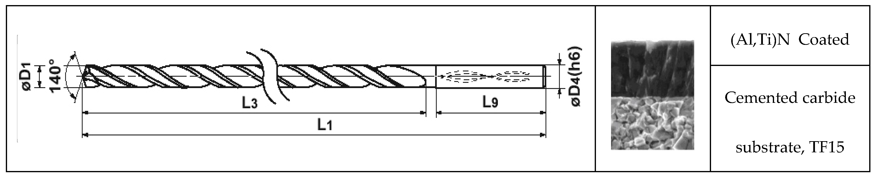
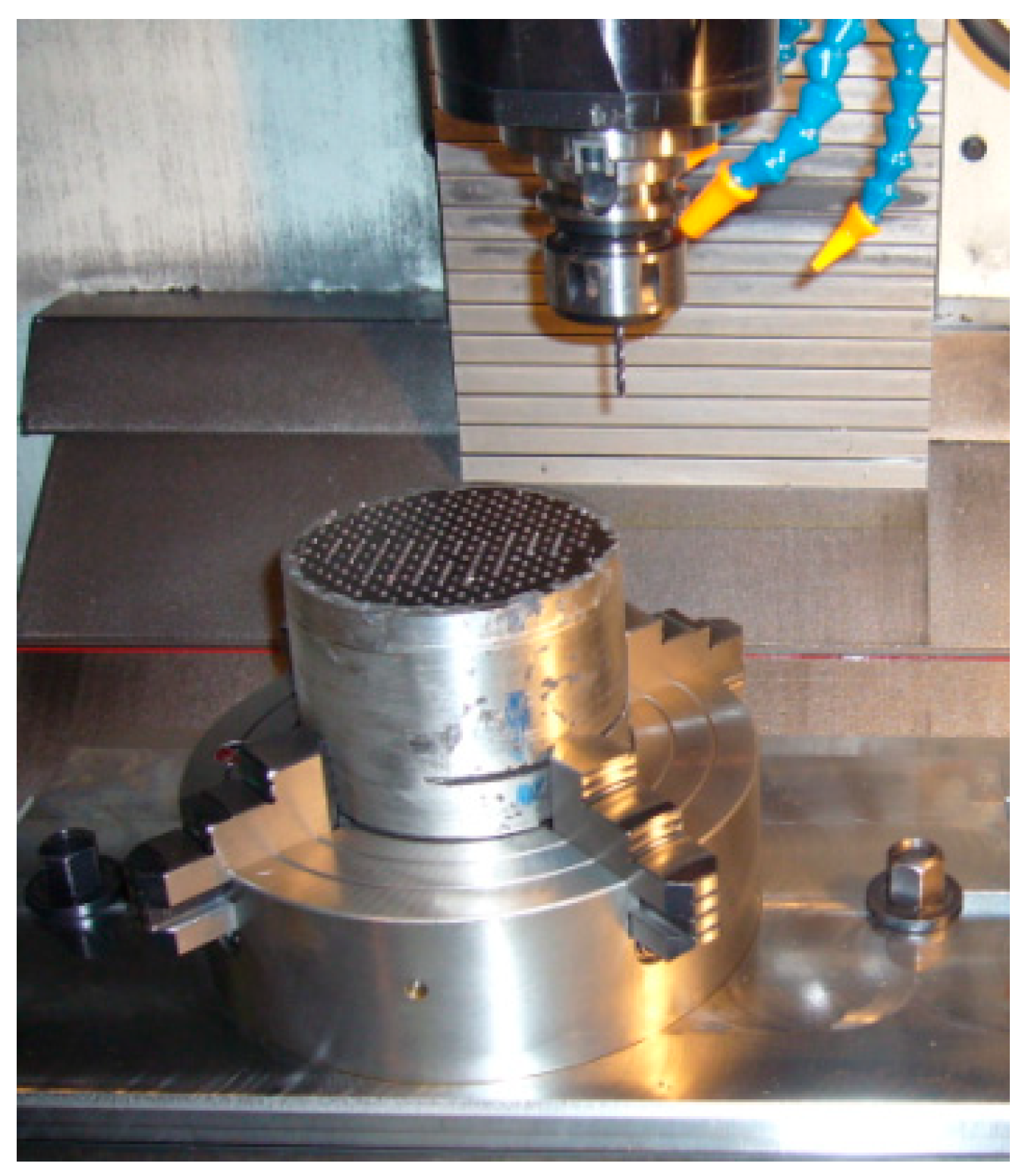
3. Experimental Procedure

This stage develops the main results of the experimental drilling operations, i.e., the evaluation of the cutting conditions in terms of tool wear, chip morphology, and surface finishing. The operations were performed with a tungsten carbide drill (see Figure 1) to a hole depth of 20 mm (L/D = 5), using an internal coolant (8.5 bar). The FU 70 W Rhenus® (Rhenus, Mönchengladbach, Germany) coolant was used in all the tests, free of ammonia and boron, but especially for aerospace applications. Tools are coated with (Al,Ti)N type (Miracle, Mitsubishi© Mitsubishi®, Tokyo, Japan), and then polished to reach a very low surface roughness. The micro-structure of TF15 carbide grade, ISO S grade (WC90%‒Co10%, grain size < 0.9 µm), has a Young’s modulus of 580 GPa. The machining tests were performed in a vertical CNC machining center, Kondia© model B640 (Kondia, Elgoibar, Spain), with maximum rotational speed of 10,000 rpm and 25 kW. It is worth mentioning that the machining of low-machinability materials could lead to problems in terms of the available nominal power in some milling operations, but not in this case.
For the experimental tests, a vertical machining center Kondia® B640, with nmax = 10,000 rpm and Pnom = 5 kW was used (Figure 2). The cutting parameters were selected according to the values recommended by the tool manufacturer and the past experience of the authors [19].
These parameters, cutting speed Vc and feed per revolution fn, are shown in Table 2. The high cost of the materials (>€500/kg) is a constraint that limits the number of tests. Due to economic reasons, only two tests were carried out for each of the cutting conditions defined. The results were obtained from the mean values of these two tests. Table 2 summarizes the cutting speed vc, the feed per revolution fn, the spindle speed n, and the feed speed vf = fn· n = fz·z·n.
After the experiments, tool wear was analyzed using the digitized images from an optical microscope (Motic SMZ Microscope, Hong Kong, China) equipped with a digital camera. The process of tool wear in a drill bit is shown in Figure 3. Some important parameters are: We, chisel edge wear width; Wf, flank wear at flank face of the cutting edge; Wo, outer corner wear width; Wm, margin wear width and Wm’, margin wear (second) width. Additionally, to describe tool rake wear, the ISO norm (ISO TC29/WG22) uses KT and KB to measure the rake wear depth and length. The mechanisms of heat generation, friction, chemical reactions, and their relative amount differ according to the work materials and the selected cutting conditions. In this case, the authors measured the wear on the rake face KB as they observed it was the most trackable, recognizable, and easy-to-measure parameter. On the contrary, flank wear here was difficult to measure as it appears in a chiseled narrow edge and looks irregular due to the brittle behavior of the tool.

4. Experimental Procedure
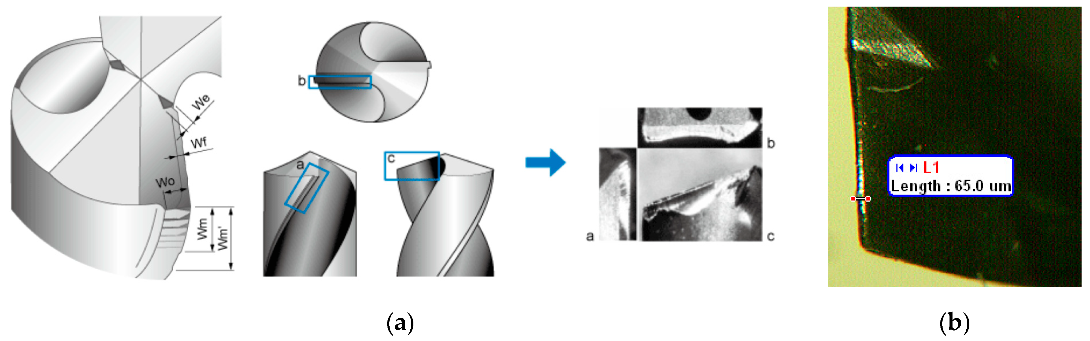
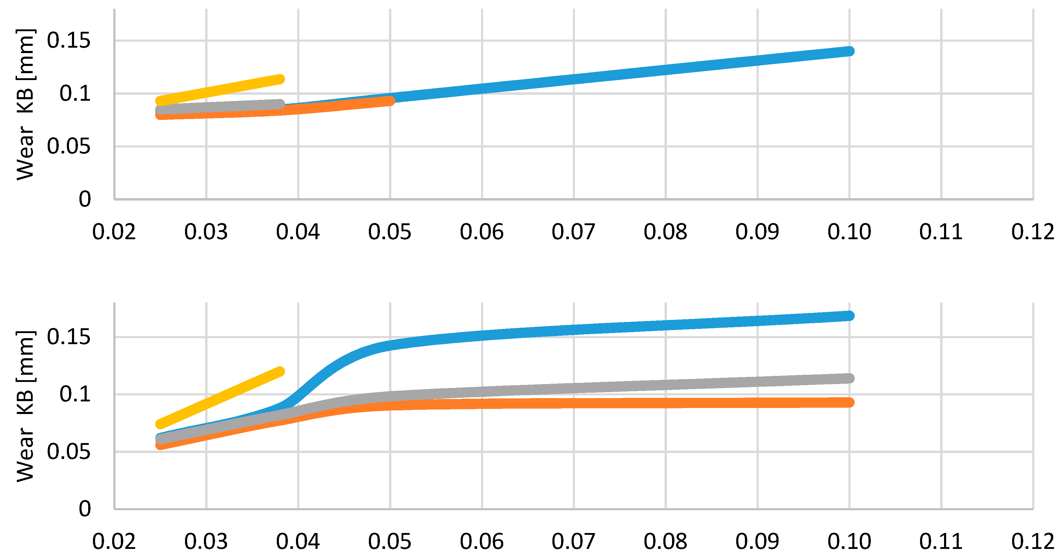
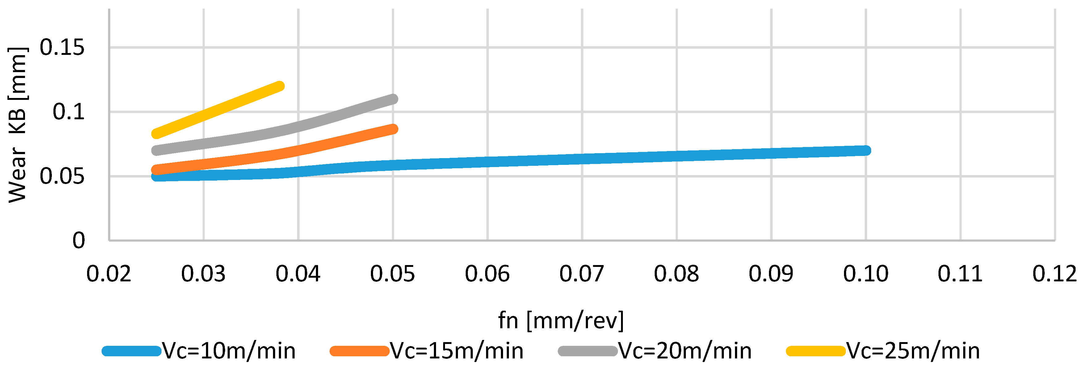
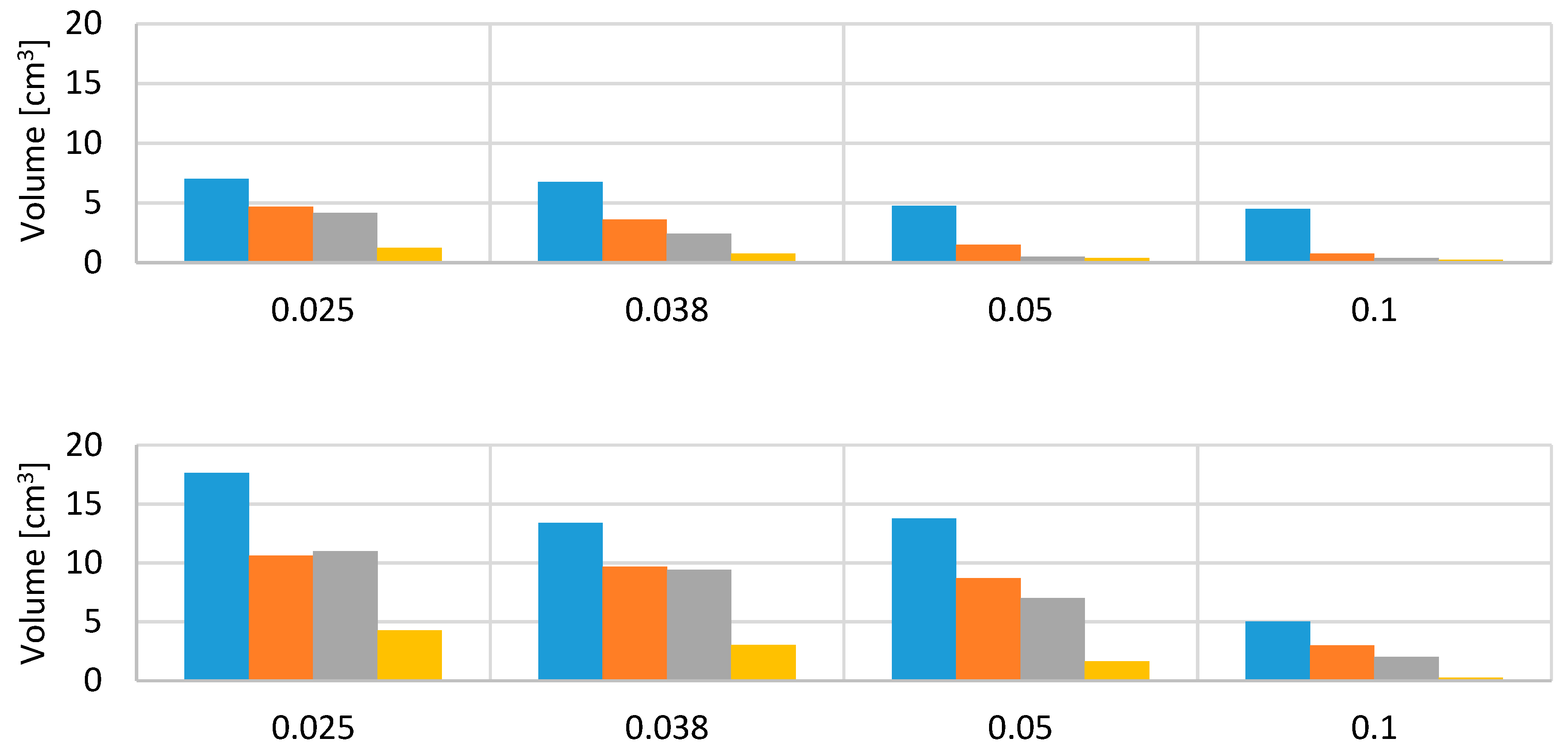
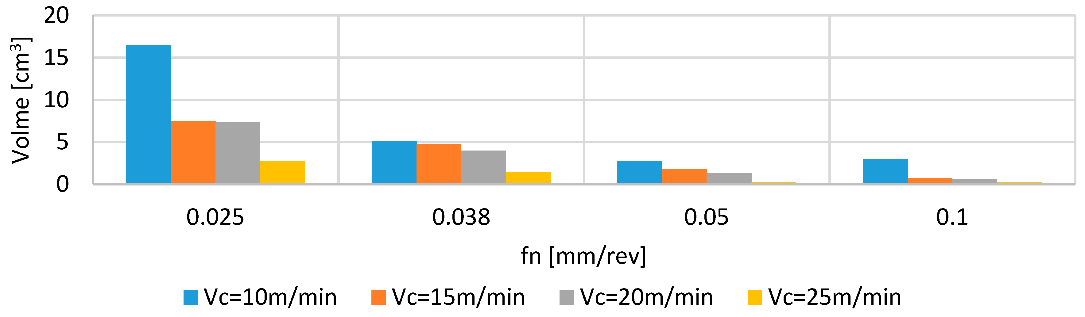
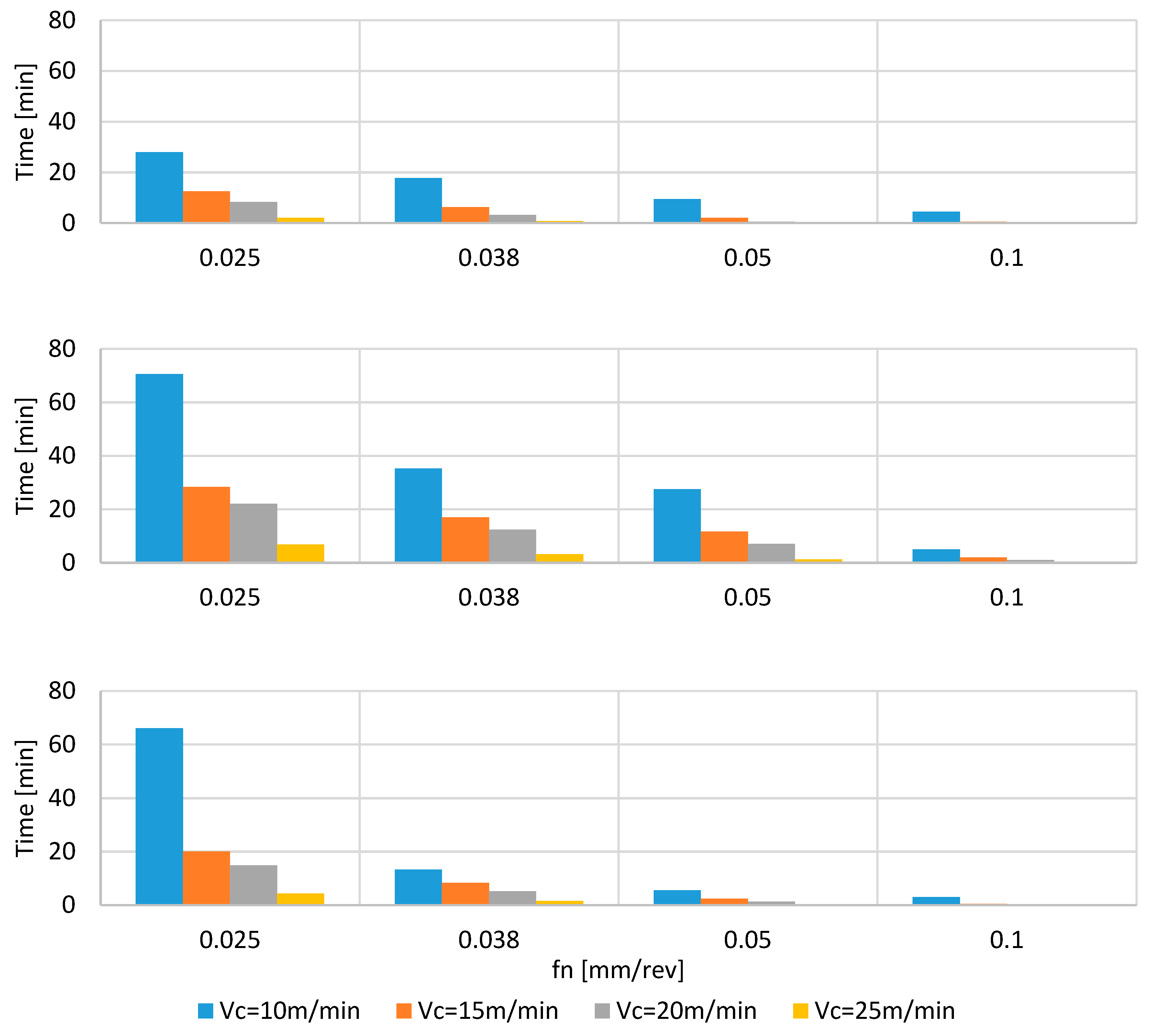
As mentioned in the above sections, three different titanium–aluminides were studied: TNB (ingot form) type and the MoCuSi types, in ingot and extruded forms. The following sections present the tool wear evolution with the associated machined volumes and machining times for a combination of cutting parameters (vc, fn).

4.1. Tool Wear

During the tests, tool wear was inspected for each flute and then the average value was considered. The procedure was to examine the tool wear every four holes; this process was repeated until tool breakage took place or the wear exceeded a fixed value of 0.15 mm. Figure 4 and Figure 5 show the measured wear values at the cutting edge and the machined volume at the final points. When there is no associated bar plot for a combination of cutting speed and feed (this happens for all materials at vc = 25 m/min and fn = 0.1 mm/rev), the tool was broken.
Cutting speed, which is often a delicate parameter for any material, is especially relevant here as it reduces the tool life dramatically. It can be seen that the optimum cutting speed varies slightly between the three types, but the optimal spindle speed range is between 10 and 15 m/min. Higher cutting speeds accelerated tool wear, leading in most cases to rapid tool failure. Specifically, values of 10–15 m/min can be used for the TNB and ingot MoCuSi types, while 10 m/min is the optimum cutting speed for the extruded MoCuSi type.
Among the three materials, the extruded MoCuSi type is the easiest to machine while the TNB type is the most difficult. Meanwhile, the cutting parameters also seem to be more restrictive (narrower) since a higher number of combinations (vc, fn) did not reach comparable values with respect to the MoCuSi ingot type due to tool failure.
Figure 4 presents different behavior among the titanium alloys in terms of the machined volume. For instance, the influence of feed rate seems to be more critical for the extruded MoCuSi than for the ingot MoCuSi. On the other hand, the cutting speed of 10 m/min should not be overpassed in TNB alloy for an acceptable productivity. A feed value of 0.1 mm/rev is always unacceptable, except for the TNB alloy, whose cutting speed is 10 m/min.
Figure 6 represents the tool life according to the mentioned stop criterion for the different tested conditions. They should be read in parallel with the values in Figure 3 and Figure 4; so, some of the tool life values correspond to the measured times until tool breakage occurs.
Additionally, for comparison purposes, some photographs were taken of the drills before and after the work (Figure 7). The Alicona© (Alicona, Graz, Austria) InfinitePlus uses optical technology to scan the specimens. For all three materials, the failure mechanisms are similar. The drills present high-depth crater wear due to chemical and erosive mechanisms that reach the secondary edge. On the other hand, surprisingly, the drill bit offered quite a good shape and appearance, suggesting that a good lubrication condition was reached at this point.
The values are again summarized for a variety of cutting speeds and feeds per revolution. In general, tool life is reduced 2–3-fold when machining TNB type with respect to MoCuSi types. The difference between the MoCusi types is subtler. The programmed feed per revolution is also a critical parameter and values beyond 0.05 mm/rev should not be used in order to avoid premature failure of the tool and save costs.
The recommended cutting conditions are:
-
TNB alloy: vc = 10 m/min, fn = 0.025 mm/rev.
-
Ingot MoCuSi: vc = 10–15 m/min, fn = 0.038 mm/rev.
-
Extruded MoCuSi: vc = 10–15 m / min, fn = 0.025 mm/rev.

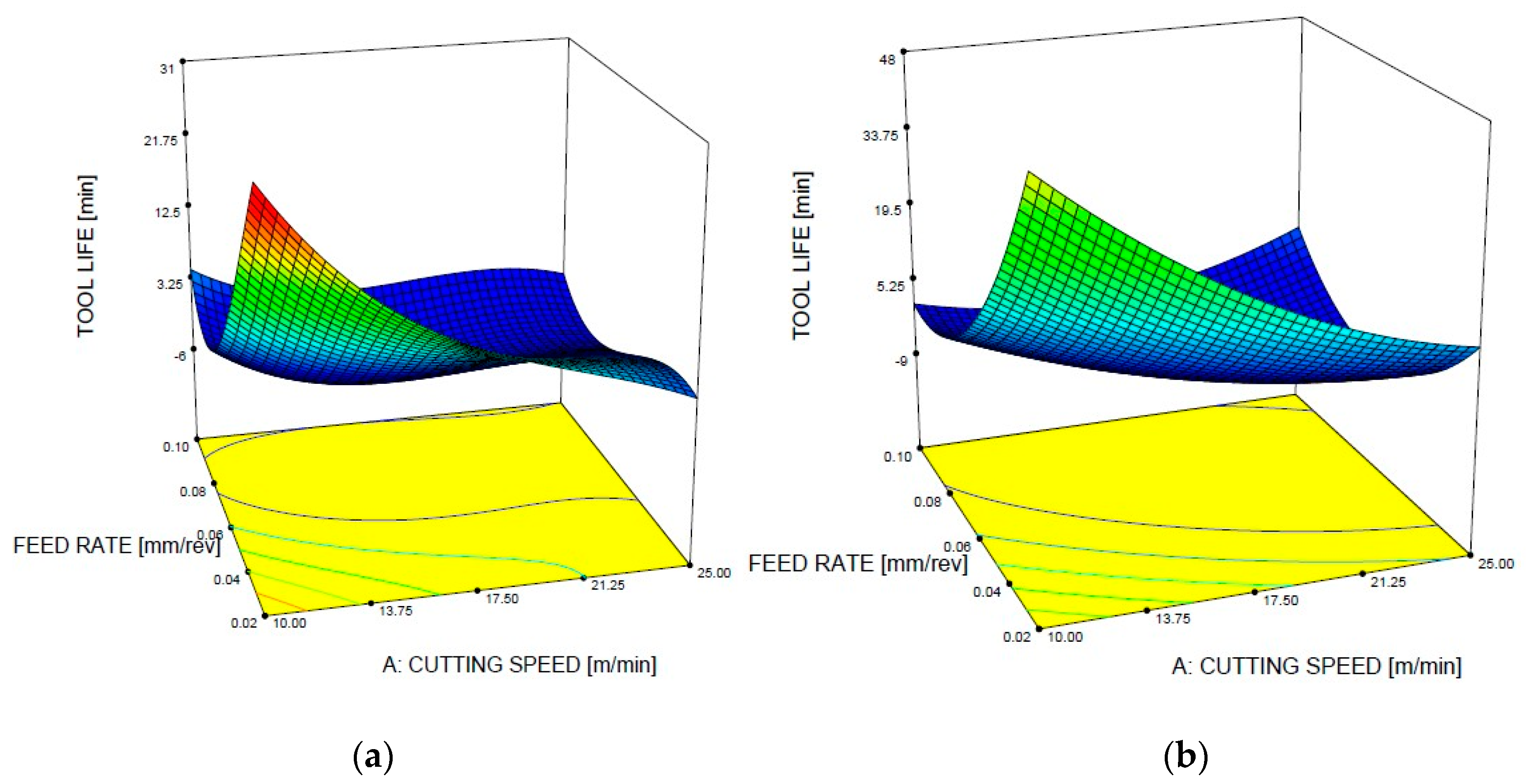
4.2. Tool Life Prediction Using DoE

Tool life can be effectively described and predicted in terms of the cutting parameters. To do so, an ANOVA analysis was done using the software Design Expert©, (Stat-Ease Inc., Minneapolis, MN, USA) following the standard methodology presented for similar problems like the dimensional precision of single tracks produced by selective laser melting [23], the fatigue properties of fiber-reinforced additively manufactured specimens [24], the surface roughness of drilled holes in the maintenance of stacked hybrid magnesium-titanium-magnesium components [25] or the wear process of drilling tools in hard drilling of AISI D2 [26]. In view of the results from Design Expert, the F-values of 79.64, 18.60, and 4.73 indicate that models are significant, with a higher dependency on the cutting speed than on the feed rate. Additionally, linear and quadratic dependencies were found to be important in the three cases studied. It is especially interesting to note the terms of those equations that consider the multiplication of cutting speed and feed per revolution (vc × fn), showing that the variables are coupled and cannot be studied independently, making the optimization of the tool’s wear during the drilling process of the three alloys a complex task. Table 3 shows estimations for the tool life, results that are especially valid in the studied parameter window. Using these functions, the tool life surface can be represented as a function of the cutting speed, vc, and the feed per revolution, fn (Figure 8). In both cases, the maximal tool life is found in the corners of the studied surface at very low values of cutting parameters, opening up a new discussion about the convenience of using low drilling conditions to extend the tool’s life—although losing productivity due to the slow drilling speeds. The answer to this question may depend on the industrial requirements of every moment, depending on the workload of each factory.
Finally, Table 4 gives the ANOVA analysis for the dependence of tool life on cutting parameters for the three alloys. For the TBN drilling case, as in the case of the MoCuSi ingot that will be presented later, the analysis reveals that the cutting speed (38.5%) and the coupled term of cutting speed times feed per revolution (33.9%) provide the main contribution to the model, while the other three terms make a lower contribution (between 3% and 17%). The high contribution of the coupled term, vc × fn, and only one of the linear terms, vc in this case, will make the intuitive process optimization by the process engineer difficult because the relationship between each input and the drill wear is mostly not independent of the other input. Only the contribution of the feed per revolution term of the model is not significant, because it surpasses the limit p < 0.10. However, the contribution of this term is very small (<3%). In any case, the existence of terms without statistical significance in the models happens often in the modeling of complex manufacturing processes [31].
For the MoCuSi ingot drilling case, the cutting speed (41.3%) and the coupled term of cutting speed times feed per revolution (31.4%) provide the main contribution to the model, while the other three terms make a lower contribution (between 7% and 11%). As in the previous case, the high contribution of the coupled term, vc × fn, and only one of the linear terms, vc in this case, will make the intuitive process optimization by the process engineer difficult because the relationship between each input and the drill wear is mostly not independent of the other input. However, for the quadratic terms of the model we cannot assure a statistically significant effect on tool life because they surpass the limit p < 0.05. However, the contribution of those two terms is very small.
Finally, the analysis for the extruded MoCuSi drilling case reveals a very balanced situation in the model, with four terms that contribute in the same range, from 21.5% to 27.8%, to the model. Only the quadratic term in the cutting speed shows a lower contribution. This kind of balanced model can be more easily optimized by the process engineer because all terms contribute equally. But in this case for three terms of the model it cannot be assured a statistically significant effect on tool´s life because they overpass the limit p < 0.05. They are all the nonlinear terms of the equation, although only for the case of the quadratic cutting speed there is not significance because it overpasses the limit p < 0.10 and this term makes the lower contribution to the model.

5. Conclusions

Gamma TiAl alloys are emerging materials that could be used for aerospace components because they work at high temperatures. Any new component from a new material involved in the aircraft engine needs to be further tested and investigated before introducing it. So, a major drawback here is the lack of knowledge, i.e., of the best cutting conditions for reliable, reproducible, accurate but productive machining of these types of alloys. In a previous study [19], the authors presented a mechanistic and useful model to estimate cutting forces and torque. However, tool wear is a critical parameter causing the rapid growth of these stationary forces and torque. It is the next problem that needs to be addressed. The high cost of the materials (>€500/kg) is a constraint that limits the number of tests. However, the experiments demonstrated the differences between the machinability of the three gamma TiAl alloys.
  • A set of drilling tests was carried out, obtaining the relationship between tool wear, cutting speed, and feed per revolution. In summary, cutting speed must be between 10 and 15 m/min and feed per revolution 0.025 mm/rev, for coated tungsten drills. The tested materials are highly dependent on cutting speed. This parameter should not be higher than 15 m/min for an acceptable tool degradation rate. For the same cutting conditions, the tool has a longer life, 2–3 times higher when machining MoCuSi ingot than in TNB. The feed per revolution also has an important effect on tool life and should not surpass the value 0.038–0.050 mm/rev. Feed value fn = 0.1 mm/rev was prohibitive in all cases.
  • These alloys present a much smaller machinability (higher specific cutting energy ps) than conventional titanium alloys such as Ti6Al4V. However, differences were noted between them. Among the three materials, the extruded and ingot MoCuSi alloys presented a similar behavior, while the TNB alloy led to more pronounced degradation. Cutting tests revealed that the most difficult-to-cut material is the TNB alloy, followed by the MoCuSi alloy in ingot form. Another point is the strong tendency of the drill to torsion failure, which is very sensitive to an increase in the cutting speed. This failure occurs at approximately 45° of the drill’s section.
  • An ANOVA analysis of the drilling test allows us to identify the influence of the considered cutting parameters in the drill’s wear. This analysis also supports the hypothesis of a different behavior between the drill’s wear for the three gamma TiAl alloys. Two of the alloys studied, MoCuSi ingot and TBN, show that the cutting speed and the coupled term of cutting speed times feed per revolution provide the main contribution to the wear model, while the other three terms of the model make a lower contribution. In some cases, the contribution of some terms is very low (<3%) and does not have statistical significance, a fact that does not affect the significance of the model due to their low contribution to the drill’s wear. For these two alloys, the high contribution of the coupled term, vc × fn, and only one of the linear terms, vc in both cases, will make the intuitive process optimization by the process engineer difficult because the relationship between each input and the drill’s wear is mostly not independent of the other input. In the case of the extruded MoCuSi, a balanced situation is found in the model, with four terms that contribute in the same range (20–30%). This kind of balanced model can be more easily optimized by the process engineer because all terms contribute equally.

Author Contributions

A.B. (Aitor Beranoagirre) and G.U. designed and performed the experiments and analyzed the experimental data. A.B. (Andrés Bustillo) and R.M. performed the statistical data processing for surface response calculation. Finally, L.N. and L.d.L. contributed resources (machine, tools, materials, etc.) and general supervision of the work.

Funding

Thanks are addressed to the UFI in Mechanical Engineering of the UPV/EHU for its support to this project, and to Spanish project DPI2016-74845-R, ESTRATEGIAS AVANZADAS DE DEFINICION DE FRESADO EN PIEZAS ROTATIVAS INTEGRALES, CON ASEGURAMIENTO DE REQUISITO DE FIABILIDAD Y PRODUCTIVIDAD and project RTC-2014-1861-4, INNPACTO DESAFIO II.

Acknowledgments

The authors acknowledge the technical assistance from Mitsubishi Carbide© and Eng. Garikoitz Goikoetxea at UPV/EHU.

Conflicts of Interest

The authors declare no conflict of interest. The funders had no role in the design of the study; in the collection, analyses, or interpretation of data; in the writing of the manuscript, or in the decision to publish the results.

Glossary

TermUnits
Creep max. temperature, Tcr°C
Cutting speed, vcm/min
Chisel edge wear width, Wemm
Density, ρkg/m3
Elongation, e%
Feed per revolution, fnmm/rev
Feed speed, vfmm/min
Feed per tooth, fzmm/ Z
Flank wear, Wfmm
Margin wear width, Wmmm
Machined volume, Vcm3
Outer corner wear width, Womm
Oxidation max. temperature, Tox°C
Crater wear depth, KTmm
Crater wear length, KBmm
Specific cutting energy, psMPa
Spindle speed, nrpm
Tool diameter, D1mm
Tool length, L1mm
Tool life, TLmin
Tool overhang, D4mm
Young modulus, EGPa

References

  1. Loria, E.A. Quo vadis gamma titanium aluminide. Intermetallics 2001, 9, 997–1001. [Google Scholar] [CrossRef]
  2. Kothari, K.; Radhakrishnan, R.; Wereley, N.M. Advances in gamma titanium aluminides and their manufacturing techniques. Prog. Aeros. Sci. 2012, 55, 1–16. [Google Scholar] [CrossRef]
  3. Nasa Technical Reports Server. Available online: https://ntrs.nasa.gov/archive/nasa/casi.ntrs.nasa.gov/20050192158.pdf (accessed on 17 November 2018).
  4. Hood, R.; Aspinwall, D.K.; Soo, S.L.; Mantle, A.L.; Novovic, D. Workpiece surface integrity when slot milling γ-TiAl intermetallic alloy. CIRP Annals-Manuf. Tech. 2014, 63, 53–56. [Google Scholar] [CrossRef]
  5. Olvera, D.; López de Lacalle, L.N.; Urbikain, G.; Lamikiz, A.; Rodal, P.; Zamakona, I. Hole making using ball helical milling on titanium alloys. Mach. Sci. Tech. 2012, 16, 173–188. [Google Scholar] [CrossRef]
  6. Ezugwu, E.O. Key improvements in the machining of difficult-to-cut aerospace superalloys. Int. J. Mach. Tools Manuf. 2005, 45, 1353–1367. [Google Scholar] [CrossRef]
  7. Sharman, A.R.C.; Aspinwall, D.K.; Dewes, R.C.; Bowen, P. Workpiece surface integrity considerations when finish turning gamma titanium aluminide. Wear 2001, 249, 473–481. [Google Scholar] [CrossRef]
  8. Aspinwal, D.K.; Dewes, R.C.; Mantle, A.L. The machining of y-TiAl intermetallic alloys. CIRP Ann. Manuf. Technol. 2005, 54, 99–104. [Google Scholar] [CrossRef]
  9. Komanduri, R.; Von Turkovich, B.F. New observations on the mechanism of chip formation when machining titanium alloys. Wear 1981, 69, 179–188. [Google Scholar] [CrossRef]
  10. Nakayama, K. The Formation of Saw-tooth Chip. In Proceedings of the First International Conference on Production Engineering, Tokyo, Japan, 1974; pp. 572–1572. [Google Scholar]
  11. Puerta Velásquez, J.D.; Bolle, B.; Chewier, P.; Geandier, G.; Tidu, A. Metallurgical Study on Chips Obtained by High Speed Machining of a Ti-6wt.%Al-4wt.%V Alloy. Mater. Sci. Eng. A 2007, 452–453, 469–474. [Google Scholar] [CrossRef]
  12. Li, R.; Riester, L.; Watkins, T.R.; Blau, P.J.; Shih, A.J. Metallurgical analysis and nanoindentation characterization of Ti-6Al-4V workpiece and chips in high-throughput drilling. Mater. Sci. Eng. 2008, 472, 115–124. [Google Scholar] [CrossRef]
  13. Corduan, N.; Himbert, T.; Poulachon, G.; Dessoly, M.; Lambertin, M.; Vigneau, J.; Payoux, B. Wear mechanisms of new tool materials for Ti–6Al–4 V high performance machining. CIRP Annals-Man. Tech. 2003, 52, 73–76. [Google Scholar] [CrossRef]
  14. Hartung, P.D.; Kramer, B.F.; von Turkovich, B.F. Tool Wear in Titanium Machining. CIRP Annals 1982, 31, 75–80. [Google Scholar] [CrossRef] [Green Version]
  15. Nouari, M.; List, G.; Girot, F.; Coupard, D. Experimental analysis and optimisation of tool wear in dry machining of aluminium alloys. Wear 2003, 255, 1359–1368. [Google Scholar] [CrossRef]
  16. Bermingham, M.J.; Kirsch, J.; Sun, S.; Palanisamy, S.; Dargusch, M.S. New observations on tool life, cutting forces and chip morphology in cryogenic machining Ti-6Al-4V. Int. J. Mach. Tools Manuf. 2011, 51, 500–511. [Google Scholar] [CrossRef]
  17. Polvorosa, R.; Suárez, A.; López de Lacalle, L.N.; Cerrillo, I.; Wretland, A.; Veiga, F. Tool wear on nickel alloys with different coolant pressures: Comparison of Alloy 718 and Waspaloy. J. Manuf. Proc. 2017, 26, 44–56. [Google Scholar] [CrossRef]
  18. Beranoagirre, A.; Urbikain, G.; Calleja, A.; López de Lacalle, L.N. Hole making by electrical discharge machining (EDM) of γ-TiAl intermetallic alloys. Metals 2018, 8, 543. [Google Scholar] [CrossRef]
  19. Beranoagirre, A.; Urbikain, G.; Calleja, A.; López de Lacalle, L.N. Drilling process in γ-TiAl intermetallic alloys. Materials 2018, 11, 2379. [Google Scholar] [CrossRef] [PubMed]
  20. Kuczmaszewski, J.; Zaleski, K.; Matuszak, J.; Pałka, T.; Mądry, J. Studies on the effect of mill microstructure upon tool life during slot milling of Ti6Al4V alloy parts. Eksploat. Niezawodn. Maint. Reliab. 2017, 19, 590. [Google Scholar] [CrossRef]
  21. Józwik, J. Evaluation of tribological properties and condition of Ti6Al4V Titanium alloy surface. Tech. Gazette. 2018, 25, 170. [Google Scholar] [CrossRef]
  22. Józwik, J.; Ostrowski, D.; Milczarczyk, R.; Krolczyk, G.M. Analysis of relation between the 3D printer laser beam power and the surface morphology properties in Ti-6Al-4V titanium alloy parts. J. Braz. Soc. Mech. Sci. Eng. 2018, 40, 215. [Google Scholar] [CrossRef] [Green Version]
  23. Uddin, M.; Basak, A.; Pramanik, A.; Singh, S.; Krolczyk, G.M.; Prakash, C. Evaluating hole quality in drilling of Al 6061 alloys. Materials 2018, 11, 2443. [Google Scholar] [CrossRef] [PubMed]
  24. Bharatish, A.; Narasimha Murthy, H.N.; Anand, B.; Subramanya, K.N.; Krishna, M.; Srihari, P.V. Assessment of drilling characteristics of alumina coated on aluminium using CO2 laser. Measurement 2017, 100, 164–175. [Google Scholar] [CrossRef]
  25. Balaji, M.; Venkata Rao, K.; Mohan Rao, N.; Murthy, B.S.N. Optimization of drilling parameters for drilling of TI-6Al-4V based on surface roughness, flank wear and drill vibration. Measurement 2018, 114, 332–339. [Google Scholar] [CrossRef]
  26. Monroy, K.; Delgado, J.; Sereno, L.; Ciurana, J.; Hendrichs, N.J. Geometrical feature analysis of Co-Cr-Mo single tracks after selective laser melting processing. Rapid Prot. J. 2015, 21, 287300. [Google Scholar] [CrossRef]
  27. Imeri, A.; Fidan, I.; Allen, M.; Wilson, D.A.; Canfield, S. Fatigue analysis of the fiber reinforced additively manufactured objects. Int. J. Adv. Manuf. Tech. 2018, 98, 2717–2724. [Google Scholar] [CrossRef]
  28. Rubio, E.M.; Villeta, M.; Valencia, J.L.; de Pipaón, J.M.S. Cutting parameter selection for efficient and sustainable repair of holes made in hybrid Mg-Ti-Mg component stacks by dry drilling operations. Materials 2018, 11, 1369. [Google Scholar] [CrossRef] [PubMed]
  29. Osman, M.H.; Tamin, N.F.; Ahmad, M.N.; Ab. Rahman, M.H.; Wahid, M.K.; Maidin, N.A.; Abu Bakar, M.H.; Azahar, A.A. Effect of cutting parameters on surface roughness in dry drilling of AISI D2 tool steel by using Taguchi method. J. Adv. Manuf. Tech. 2018, 12, 535–546. [Google Scholar]
  30. López de Lacalle, L.N.; Pérez, J.; Llorente, J.I.; Sánchez, J.A. Advanced cutting conditions for the milling of aeronautical alloys. J. Mater Process Technol. 2000, 100, 1–11. [Google Scholar] [CrossRef]
  31. Teixidor, D.; Grzenda, M.; Bustillo, A.; Ciurana, J. Modeling pulsed laser micromachining of 370 micro geometries using machine-learning Techniques. J. Int. Manuf. 2015, 26, 801–814. [Google Scholar] [CrossRef]
Figure 1. Drill bit (D1 = 4 mm, L1 = 74 mm, L3 = 36 mm, L9 = 36 mm, D4 = 6 mm). (Courtesy of Mitsubishi©).
Metals 09 00297 g001
Figure 2. Experimental tests in a Kondia B640 multitasking milling center.
Metals 09 00297 g002
Figure 3. (a) Wear parameters in drilling and common locations (a. Secondary cutting edge; b. Main cutting edge, flank face; c. Main cutting edge, rake face), courtesy of Mitsubishi©; (b) Wear measurement on the rake face.
Metals 09 00297 g003
Figure 4. Tool wear for drilling of the TNB alloy (up), ingot TNB (middle), and extruded MoCuSi (down).
Metals 09 00297 g004aMetals 09 00297 g004b
Figure 5. Machined volume for drilling of the TNB alloy (up), ingot MoCuSi alloy (middle), and extruded MoCuSi alloy (down).
Metals 09 00297 g005aMetals 09 00297 g005b
Figure 6. Tool life comparison for drilling of the TNB alloy (up), ingot MoCuSi alloy (middle) and extruded MoCuSi alloy (down).
Metals 09 00297 g006
Figure 7. Perspective and frontal views of new (up) and worn (down) drill.
Metals 09 00297 g007
Figure 8. (a) Surface response for tool life estimation (TNB); (b) surface response for tool life estimation (extruded MoCuSi).
Metals 09 00297 g008
Table 1. Properties of titanium alloys and superalloys.
PropertyTi Alloysα-2γOther Superalloys
Density ρ (gr/cm3)4.544.844.048.3
Young modulus E (GPa)110145176207
Creep max. temperature Tcr (°C)5407309001090
Oxidation max. temp. Tox (°C)5907058151090
Ductility or elongation (in %)152–41–33–10
Elongation, operating Temperature %155–125–1210–20
Table 2. Cutting conditions for the drilling tests.
vc [m/min]fn [mm/rev]n [rpm]vf [mm/min]
100.025, 0.038, 0.050, 0.10079619.9, 30.2, 39.8, 79.6
150.025, 0.038, 0.050, 0.100119429.9, 45.4, 59.7, 119.4
200.025, 0.038, 0.050, 0.100159239.8, 60.5, 79.6, 159.2
250.025, 0.038, 0.050, 0.100198949.7, 75.6, 99.5, 198.9
Table 3. Tool life estimation from ANOVA analysis.
MaterialsTool Life [min]
TNB alloyTL = 149.97 − 16.603 × vc − 1312.081 × fn + 102.475 × vc × fn + 0.6758 × vc2 − 491.231 × fn2
MoCuSi alloy (ingot)TL = 161.94 − 8.8328 × vc − 821.629 × fn + 42.350 × vc × fn + 0.130471 × vc2 + 5861.472 × fn2
MoCuSi alloy (extruded)TL=139.21−7.25716×vc − 2069.066×fn + 36.759×vc×fn + 0.11391×vc2 + 9281.094×fn2
Table 4. ANOVA analysis.
MaterialsSourceSum of SquaresDegrees of FreedomMean SquareF
Value
P ValueContribution (%)
TNB alloyModel906.099100.6879.64< 0.0001-
vc36.23136.2328.660.001738.51
fn2.6412.642.090.19862.81
vc × fn31.93131.9325.260.002433.94
vc215.81115.8112.500.012316.798.11
fn27.4817.485.920.05107.95
Residual7.5861.26---
MoCuSi ingotModel4552.025910.4018.60<0.0001-
vc987.151987.1520.170.001241.32
fn262.441262.445.360.043110.98
vc × fn749.861749.8615.320.002931.39
-
vc2170.051170.053.470.09197.11
fn2219.711219.714.490.06029.20
Residual489.461048.95---
Extruded MoCuSiModel2790.295558.064.730.0178-
vc714.571714.576.050.033627.87
fn602.241602.245.100.047523.49
vc × fn564.951564.954.790.053522.06
vc2129.611129.611.100.31945.07
fn2550.851550.854.670.056121.51
Residual2790.295558.064.730.0178-

