Article

Comparison of Transverse Uniform and Non-Uniform Secondary Cooling Strategies on Heat Transfer and Solidification Structure of Continuous-Casting Billet

1
State Key Laboratory of Advanced Metallurgy, University of Science and Technology Beijing, Beijing 100083, China
2
Xiangtan Iron & Steel Co., Ltd of Hunan Valin., Xiangtan 411101, China
3
Jiangsu Boji Spraying Systems Co., Ltd., Yangzhou 225267, China
*
Author to whom correspondence should be addressed.
Metals 2019, 9(5), 543; https://doi.org/10.3390/met9050543
Submission received: 9 April 2019 / Revised: 7 May 2019 / Accepted: 8 May 2019 / Published: 10 May 2019
(This article belongs to the Special Issue Refining and Casting of Steel)

Abstract

:
Water flux distribution largely influences the heat transfer and solidification of continuously-cast steel billets. In this paper, a secondary cooling strategy of transverse non-uniform water flux (i.e., higher flux density on billet center), was established and compared with the uniform cooling strategy using mathematical modeling. Specifically, a heat transfer model and a cellular automaton finite element coupling model were established to simulate the continuous casting of C80D steel billet. The water flux was measured using different nozzle configurations to assist the modeling. The mathematical results were validated by comparing the surface temperature and the solidification structure. It is shown that the non-uniform cooling strategy enables the increase of corner temperature and reduction in surface temperature difference, while a higher reheating rate is found on the surface center of the billet. Moreover, the non-uniform cooling strategy can enhance the cooling effect and refine the solidification structure. Accordingly, the liquid pool length is shortened, and the equiaxed crystal density is increased along with the decreased equiaxed crystal ratio. The uniform cooling strategy contributes to reducing internal cracks of billet, and the non-uniform one is beneficial for surface quality and central segregation. For C80D steel, the non-uniform cooling strategy outperforms the uniform one.

1. Introduction

Continuous casting is the main method of steel production at present, and its cooling and solidification process largely influences the quality of blanks. During casting, the cooling of the blanks is realized in the mold, secondary cooling zone, and air-cooling zone. Since the cooling conditions in the mold and the air-cooling zone are relatively steady, the control of solidification mainly focuses on the secondary cooling zone. Secondary cooling is particularly important, as it is closely related to the heat transfer and solidification structure of the blank, and therefore influences the formation of defects, such as cracks [1,2,3], central pipe [4], and segregation [5,6,7]. To minimize the defects, water flux and its distribution were frequently resorted to as a means to improve the product quality through both numerical simulation and industrial trials [8,9,10].
Secondary cooling is achieved by spraying water on the blank using arranged nozzles and is directly influenced by the water flux distribution. The nozzle arrangement varies for different cross-sectional casting blanks, such as slab, billet, and bloom. For a continuous casting slab, there is a wide range of water flux on the slab surface owing to its large section size, and the nozzle collocations are usually complex in the secondary cooling zone. Therefore, the water flux distribution needs to be taken into consideration along both the transverse direction and casting direction [10,11,12,13]. Moreover, the transverse water flux distribution can be used as a method to improve the quality of slab by the collocations of nozzles. Wang et al. [14] optimized the water flux distribution along slab width direction through the arrangement of spraying nozzles, and the centerline macro-segregation and transverse cracking were improved significantly. Long et al. [15] proposed that a uniform solidified shell in the transverse direction was beneficial to mitigating slab central macro-segregation, thanks to the optimized transverse water flux distribution.
As for small sectional blanks, typically including square billet and rectangular billet, there is usually only one spraying nozzle along the transverse direction on one side of the billet. The transverse water flux distribution is not as complicated as slab and normally assumed to be uniform in the literature [6,7,8,16,17,18]. Zeng et al. [6] investigated the solidification structure and macro-segregation of a rectangular billet under different secondary cooling conditions. Ma et al. [18] optimized secondary cooling water distribution to improve billet quality. Their works mainly focus on the total water flux and its distribution along the casting direction, and is not related to the uniformity of transverse water flux distribution, which depends on the nozzle type, installation parameter, and inevitable aging and clogging. The change of transverse water flux distribution obviously affects the solidification behavior of the billet. What is worth mentioning is that Assuncao et al. [19] compared uniform and non-uniform water flux distribution on the thermal behavior of a round billet in a recent work. They found that there is a big difference between them, and the thermal behavior of the billet is more accurate using the measured water flux distribution. However, round billet and square billet still differs greatly, especially at the corner of square billet, which is largely associated with corner defects. Until recently, the transverse water flux distributions of square billet under different nozzle collocations have drawn little attention, and the heat transfer behavior and solidification structure of the billet are still unclear under different transverse water flux distributions.
The present work shed lights on the transverse water flux distribution in the secondary cooling zone of square billet. Two similar continuous casters with different types and arrangements of spraying nozzles were studied. Transverse water flux distribution was measured using an apparatus, and two cooling strategies were obtained, including transverse uniform and non-uniform distribution of secondary cooling water. A heat transfer model and a cellular automaton finite element (CAFE) coupling model were used to analyze the heat transfer and solidification structure of the billet, respectively. The main differences between the two cooling strategies were compared on the solidification behavior of the billet, and the advantages of each cooling strategy were discussed.

2. Brief Description of the Studied Continuous Caster

Two similar continuous casters are involved in the present study. Both casters are four-strand circular-arc casters with a curved mold that mainly produce billets with a small section size (150 mm × 150 mm). The two casters have their own features and produce different steel grades. At the mold, electromagnetic stirrer (EMS, Produced by Hunan Kemeida Electric Co., Ltd., Yueyang, China) is applied on each caster and the stirrer can generate a rotating magnetic field. The schematic diagrams of the casters and nozzle arrangements are shown in Figure 1. Caster 1 and Caster 2 have similar cooling zones, however, the length of each cooling zone and nozzle arrangement at the secondary cooling zone are different. For Caster 1, a full cone jet nozzle and flat jet nozzle (Produced by Jiangsu Boji Spraying Systems Co., Ltd., Yangzhou, China) are used in the foot-roller zone and the secondary cooling zone, respectively. Moreover, all the nozzles overspray on the billet surface and the flat jet nozzles deflect at an angle of 30°. With regard to Caster 2, two full cone jet nozzles (Produced by Beijing Zhongye Metallurgical Equipment Manufacturing Co., Ltd., Beijing, China) are installed on the width direction in the foot-roller zone, and one full cone jet nozzle is installed on the width direction that just fully covers the billet surface in the secondary cooling zone.

3. Spraying Nozzle Measurement of Water Flux Distribution

The water flux distribution largely influences the local thermal behavior of billet during continuous casting [11,19]. It is essential to clarify the effect of water flux distribution on the secondary cooling. Under the practical installation conditions, transverse water flux distributions were measured in the secondary cooling zone of Caster 1 and Caster 2. The water flux distribution along the casting direction was not taken into consideration due to the limitation of the experimental set-up.

3.1. Experimental Apparatus

Measurements were carried out using an experimental apparatus that can quantify the water flow rate, spraying angle, and water flux distribution of the spraying nozzle. Figure 2 shows the schematic diagram of the experimental apparatus. The apparatus includes water tank, gas tank, water-gas regulator, control system, and water collector. Water tank and gas tank supply sufficient water pressure and gas pressure, and the water-gas regulator is used to adjust the water pressure and the gas pressure to a desired value. The water collector consists of a row of grooves and one pressure sensor is installed under each groove. The width of each groove is 25 mm.

3.2. Water Flux Distribution Measurement

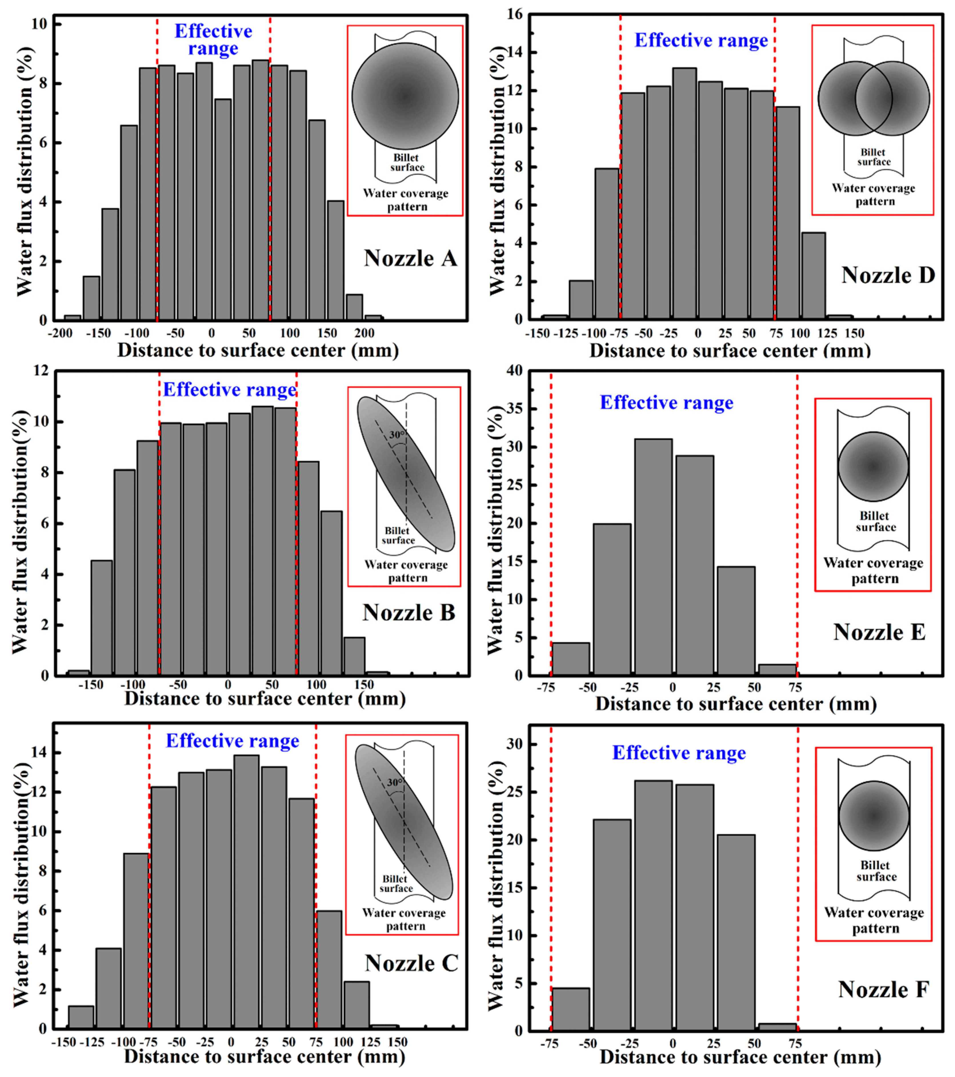
Six actual water spraying nozzles were adopted in the experiment. Among the nozzles, Nozzle A, Nozzle B, and Nozzle C were used in the foot-roller zone, secondary cooling zone A, and secondary cooling zone B of Caster 1, respectively. Nozzle D, Nozzle E, and Nozzle F were used in the foot-roller zone, secondary cooling zone A, and secondary cooling zone B of Caster 2, respectively. The type number and jet type of the nozzles were different. Nozzle A, Nozzle D, Nozzle E, and Nozzle F were full cone jet nozzles, while Nozzle B and Nozzle C were flat jet nozzles. In practical casting process, the water pressure and jet distance of nozzles are listed in Table 1. The spraying angle and water flux distribution were measured, as shown in Table 1 and Figure 3.
In Figure 3, it can be seen that the water flux distribution is non-uniform and generally symmetric for each spraying nozzle, and there is more water on the spraying center and less water on the spraying edge. As the billet width is 150 mm, an effective range on the billet surface is counted from −75 mm to 75 mm. In the effective range, the water flux distributions of Nozzle A, Nozzle B, Nozzle C, and Nozzle D are generally uniform, while the water flux of Nozzle E and Nozzle F is unevenly distributed with a higher water flow rate on the center and a lower one around the corner. Corresponding to different cooling zones of the continuous casters, it can be found that the transverse water flux distributions are relatively uniform in the foot-roller zones of Caster 1 and Caster 2. In the secondary cooling zone, the transverse water flux distributions of Caster 1 and Caster 2 are uniform and non-uniform, respectively. It indicates that Caster 1 and Caster 2 have two different cooling strategies, namely transverse uniform and non-uniform secondary cooling strategies.

4. Numerical Modeling and Validation

Caster 1 was chosen in the numerical model to study the solidification behaviors of the billet under different secondary cooling strategies. The water flux distribution in the secondary cooling zone of Caster 2 was applied on Caster 1 to compare with the original one, and two cooling modes were determined as follows.
Mode 1: Original water flux distribution in the secondary cooling zone was adopted on Caster 1, and the transverse water flux distribution was regarded as uniform on the billet surface, as shown in Figure 4a.
Mode 2: Water flux distribution in the secondary cooling zone of Caster 2 was applied on Caster 1. The transverse distribution of secondary cooling water is non-uniform, and there is more water on the surface center and less water on the surface edge of the billet, as shown in Figure 4b.
In the simulation, all the other parameters of Mode 1 and Mode 2 were the same except for the different transverse water cooling in the secondary cooling zone.

4.1. Model Development

4.1.1. Heat Transfer Model

Some assumptions were made to simplify the mathematical model.
  • The heat transfer in casting direction and meniscus was neglected.
  • The convective heat transfer was equivalent to the conductive heat transfer by increasing the thermal conductivity of liquid and mushy zone.
  • The heat transfer of radiation, contact with the supporting roller, and cooling water in the secondary cooling zone were included by an integrated heat transfer coefficient.
  • The water flux distribution along the casting direction of each segment was uniform in the secondary cooling zone.
  • The density, solid fraction, and thermal conductivity of the steel were temperature dependent.
  • The dimensional change caused by solidification shrinkage was neglected on the analysis of temperature and solidification structure of the billet.
Based on the assumptions, a two-dimensional unsteady state heat transfer equation was expressed as follows:
ρ C P , e f f T τ = x ( λ e f f T x ) + y ( λ e f f T y )
where ρ is the density of steel in kg/m3; Cp,eff is the effective specific heat in J/(kg·K); T is the temperature of steel in K; τ is the calculation time in s; λeff is the effective thermal conductivity in W/(m2·K); x is the distance from the billet center along transverse direction in m, and y is the distance from billet center on the inner radius face in thickness direction in m.
The effect of latent heat on the solidification of steel at the mushy zone was incorporated into the effective specific heat, and represented by enthalpy, as shown in the Equations (2) and (3).
C p , e f f = C P L · f s T
H = 0 T C P d T + L ( 1 f s )
where CP is the actual specific heat in J/(kg·K); L is the latent heat in J/kg; H is the enthalpy in J/kg and fs is the solid fraction.
A slice moving method was applied in the simulation. To simplify the calculation, the geometric model of the slice adopted a quarter of the cross section of the billet with a thickness of 10 mm and the rounded corners were neglected, namely with a dimension of 75 mm × 75 mm × 10 mm. It was assumed the slice moved along the casting direction from the mold to the foot-roller zone, the secondary cooling zone, and finally the air-cooling zone. In the mold, the heat flux was obtained from a heat balance of the cooling water, and equalized to the empirical equation, as shown in Table 2. To consider the effect of the gap on the heat transfer, a decreasing heat flux was used from the billet center to the corner, and the heat flux at the corner decreased with the increase of distance from the meniscus [10]. In the foot-roller zone and the secondary cooling zone, the surface temperature of the billet is mostly above the Leidenfrost point. The heat flux was characterized by an integrated heat transfer coefficient, which was a function of water flux density. In the air-cooling zone, the radiation was the main heat transfer pattern and the heat extraction was obtained according to the Stefan–Boltzmann law.
The water flow rates, boundary conditions, and calculated formulae [20,21,22] of different cooling zones are listed in Table 2. In Table 2, qm, qf, qs, and qa are the heat flux of the mold, the foot-roller zone, the secondary cooling zone, and the air-cooling zone, respectively, W/m2; hf and hs are the heat transfer coefficient of the foot-roller zone and the secondary cooling zone, respectively, W/(m2K); T, Tf, Ts, and Ta are the temperature of the billet surface, the water temperature of the foot-roller zone, the water temperature of the secondary cooling zone, and the environment temperature of the air-cooling zone, respectively, K; β is a coefficient between the shape of the mold and parameter of casting, W/(m2·s1/2); t is the holding time in the mold, s; σ is Stefan–Boltzmann constant, W/(m2·K4); ε is the radiation coefficient. The numerical values of qm, β, hf, and hs can be obtained by a calculation using casting parameters.
In the simulation, the boundary conditions of Mode 1 and Mode 2 were treated as the same in the mold, the foot-roller zone, and the air-cooling zone. As for the secondary cooling zone, the boundary condition of Mode 1 was uniform. For Mode 2, the billet surface was divided into three sections along the transverse direction, and the boundary condition of each section was separated according to local water flux density, as shown in Figure 4. Whether Mode 1 or Mode 2, the boundary condition along the casting direction was constant at each secondary cooling zone.

4.1.2. Nucleation Model

Procast software was used to establish the nucleation model and dendritic tip growth model. A continuous nucleation distribution function, dn/d(∆T) was used to describe the grain density change [23], and dn is induced by the increase of undercooling, d (∆T). The distribution function is expressed by Equation (4):
d n d ( Δ T ) = n max 2 π Δ T σ exp [ 1 2 ( Δ T Δ T max Δ T σ ) 2 ]
where ∆T is the calculated local undercooling in K; ∆Tmax is the mean undercooling in K; ∆Tσ is the standard deviation in K, and nmax is the maximum nucleation density in m−3.

4.1.3. Dendritic Tip Growth Model

The KGT (Kurz, Giovanola, Trivedi) model [24,25] was used as the model of growth kinetics of a dendrite tip in the C80D steel. Based on the marginal stability criterion, Equation (5) is obtained.
V 2 A + V B + C = 0
where V is the growth velocity of a dendrite tip, and A, B, and C are expressed by Equations (6) to (8).
A = π 2 Γ p 2 D 2
B = m C 0 ( 1 k 0 ) ξ C D [ 1 ( 1 k 0 ) I v ( P ) ]
C = G
where Г is the Gibbs–Thomson coefficient; P is the Peclet number for solute diffusion; D is the diffusion coefficient in the liquid; m is the liquidus slope; C0 is the initial concentration; k0 is the partition coefficient; Iv(P) is the Ivantsov function; ξc = π2/(k0P) closes to unity at a low temperature gradient, and G is the temperature gradient. For the dendrite growth regime, G has little effect on the growth velocity V and can be regarded as zero.
Moreover, the undercooling at dendrite tip, ∆T, is expressed as Equation (9). The relationship between the undercooling ∆T and growth velocity V can be calculated by substituting an arbitral value of the Peclet number into Equations (5) and (9). The material properties [26,27] of C80D steel that were used in the simulation are given in Table 3. The partition coefficients and liquidus slopes were assumed to be constants from liquidus to solidus.
Δ T = m C 0 [ 1 1 1 ( 1 k 0 ) I v ( P ) ] + 2 Γ r
where r is the dendrite tip radius, r = (2D·P)/V.
To accelerate the computational speed, a set of values for the undercooling and growth velocity of the dendrite tip are calculated in Equations (5) and (9). Then the following Equation (10) is obtained.
V = a 2 Δ T 2 + a 3 Δ T 3
where a2 and a3 are the fitting coefficients of the multinomial of dendrite tip growth velocity. The values of a2 and a3 were calculated using the material properties shown in Table 3, and the specific values are 3.041 × 10⁻⁶ m/(s·K2) and 2.146 × 10⁻⁵ m/(s·K3), respectively.

4.2. Material Properties

C80D steel was studied and its main chemical composition has been given in Table 3. Variations of solid fraction, enthalpy, thermal conductivity, and density with temperature were calculated using a thermodynamic database from JMatPro software according to the steel composition, as shown in Figure 5. The flow of liquid steel, which results from the initial flow from the submerged nozzle, natural convection, and external force of mold electromagnetic stirring (MEMS), can enhance the heat transfer during solidification. The thermal conductivities of the liquid and the mushy zone were enlarged to consider the effect of fluid flow [17,28]. The thermal conductivity of solid adopted calculated values, five times the thermal conductivity of solidus was adopted for the liquid phase, and the thermal conductivity of the mushy zone was assumed to change with temperature linearly.

4.3. Model Validation

4.3.1. Casting Parameters

Industrial tests were conducted on Caster 1 to calibrate the heat transfer model and the CAFE coupling model. The main casting parameters of the tests are listed in Table 4.

4.3.2. Heat Transfer Model Validation

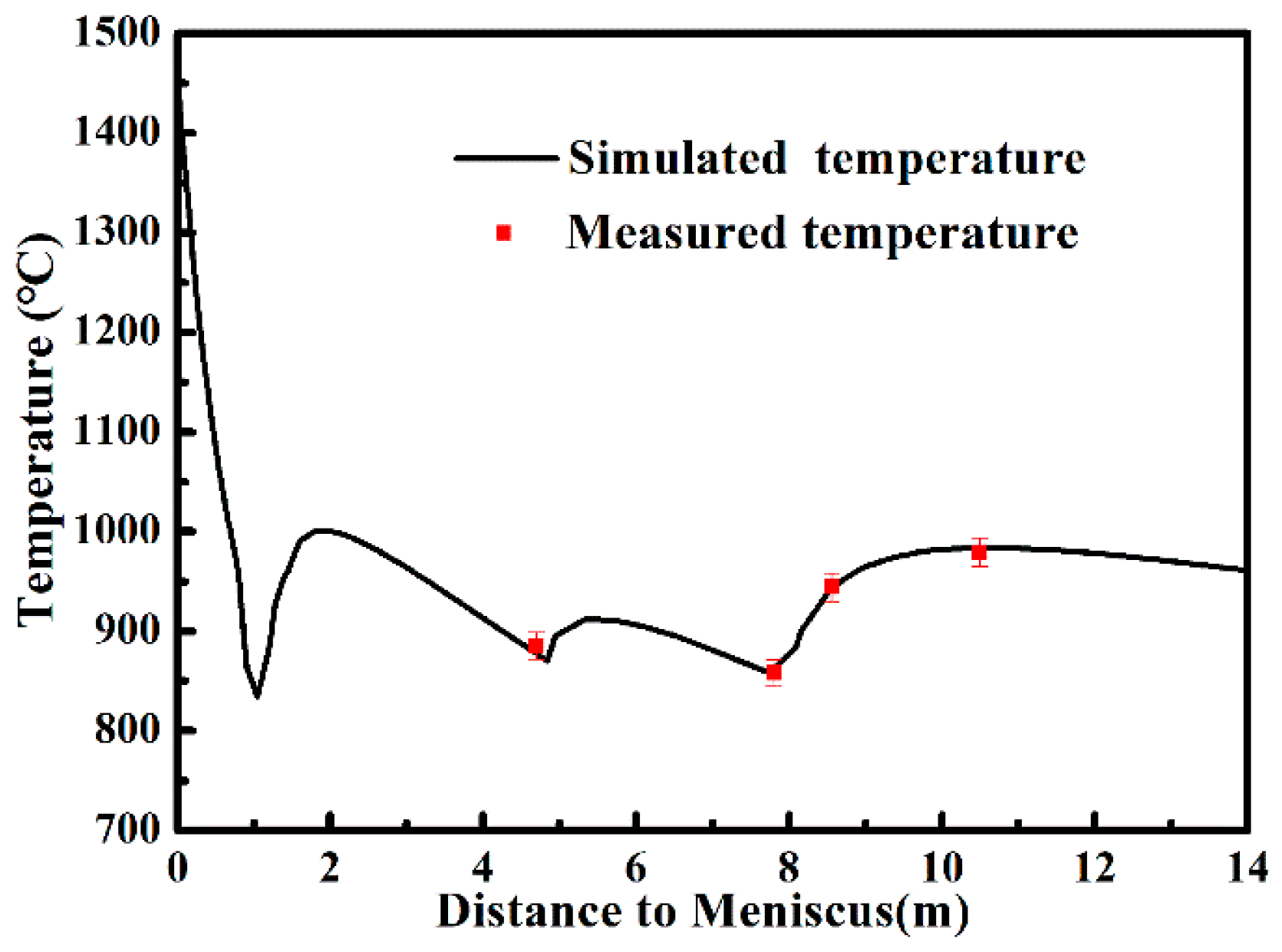
The surface temperature of the billet was measured using an infrared radiation pyrometer, the error range of which is ±1.5%. During the measurement, the pyrometer was perpendicular to the surface center of the side arc and peak values were adopted as the local temperature. The temperature of the billet was also calculated by the heat transfer model under practical casting parameters. Figure 6 shows the comparison between the calculated temperature and the measured temperature. A good agreement was obtained between the mathematical and the actual results within the error range. It can be concluded that the heat transfer model is generally reliable.

4.3.3. CAFE Coupling Model Validation

The transverse billet sample was sliced, polished and etched by hydrochloric acid, and then the actual solidification structure was revealed. From the billet surface to the center, the solidification structure features with an outer chilled layer, a columnar crystal zone, a mixed crystal zone, and an equiaxed crystal zone. Moreover, the columnar crystal deflects on account of MEMS. The deflection was neglected in the simulation. MEMS can also enlarge the equiaxed crystal zone, which is considered by adjusting the maximum nucleation density. The solidification structure was simulated using the CAFE coupling model. The maximum nucleation density was adjusted to match the simulated solidification structure and the actual one, and finally was set as 2.5 × 10⁹ m−3. Figure 7 shows the comparison of the actual solidification structure and the simulated one. Each zone of the actual solidification structure and the simulated one shares basically the equivalent area. This result indicates the selected nucleation parameters are reasonable and the CAFE coupling model is reliable to simulate the solidification structure of C80D steel.

5. Results and Discussion

Following the casting parameters shown in Table 4, comparisons were made between transverse uniform and non-uniform distribution of secondary cooling water on the heat transfer behavior and solidification structure.

5.1. Comparison of Surface Temperature

Figure 8 comparatively presents the 3D topography of the surface temperature variation under the two cooling strategies. Their temperature variations generally show a similar and typical tendency. The surface temperature starts at around 1500 °C and rapidly drops to less than 800 °C caused by the intense cooling in the mold and foot-roller zone. Thereafter, the temperature fluctuates in different sections of the secondary cooling zone owing to the change of cooling intensity, and finally decreases slowly in the air-cooling zone. As the cooling condition in the mold and the foot-roller zone are the same, the surface temperature distributions of Mode 1 and Mode 2 exhibit no difference. In the secondary cooling zone of Mode 1, a wide range low-temperature zone (less than 700 °C) is observed near the billet corner, and the temperature difference between the corner and the center is large. For Mode 2, the cooling is strengthened at the center and weakened at the corner owing to more water on the surface center and less water on the surface edge. As a result, the low-temperature zone is narrowed and the temperature difference along the width direction becomes small. When billet enters into the air-cooling zone, the billet surface reheats and the temperature distribution tends to become uniform gradually.
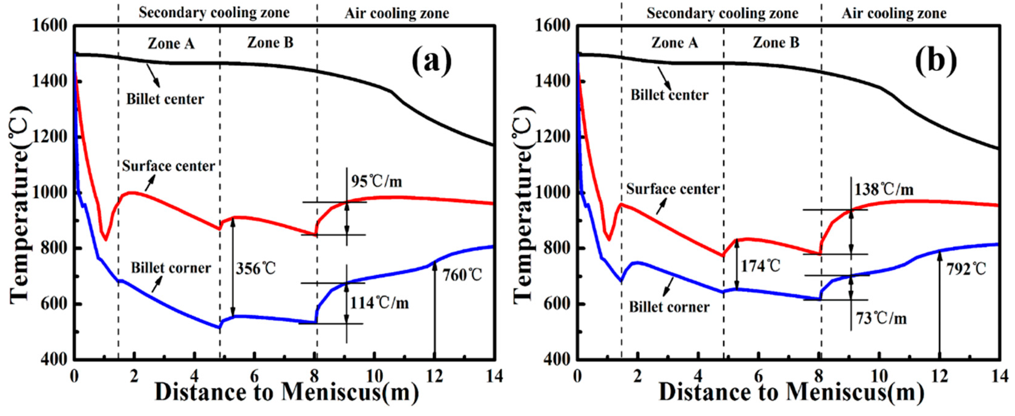
To analyze the temperature variation quantitatively, the temperature variations of billet center, surface center, and billet corner are highlighted in Figure 9. It shows that the temperature of the billet center keeps nearly constant until a fast drop at the final stage of solidification, and there exists little difference between Mode 1 and Mode 2. The corner temperature in the secondary cooling zone of Mode 1 is below 600 °C mostly, while that of Mode 2 is all above 600 °C. For Mode 2, the temperature difference of the billet corner and surface center is 174 °C, much lower than that of Mode 1 with a value of 356 °C, which means a more uniform transverse temperature distribution of Mode 2, beneficial for surface quality [29].
When the billet enters into the air-cooling zone, the reheating rates of the billet corner and surface center for Mode 1 are 114 °C/m and 95 °C/m, respectively. As for Mode 2, the reheating rate of the billet corner is decreased to 73 °C/m and that of surface center is increased to 138 °C/m. These effects may result in reheat-type internal cracks as the reheating rate exceeds 100 °C/m [30]. At the straightening point, the corner temperature of Mode 2 is 792 °C, which is 32 °C higher than that of Mode 1. The corner of the billet is a crack-prone area on account of the low temperature. The transverse non-uniform secondary cooling strategy is able to increase the corner temperature and contribute to avoiding the third temperature zone of low ductile for C80D steel, thus reducing the possibility of generating corner cracks [29].

5.2. Comparison of Internal Temperature

The temperature distributions of a one-fourth cross section at various positions are exhibited in Figure 10. Except for the temperature near the billet corner, the difference of internal temperature between Mode 1 and Mode 2 is not as significant as the surface temperature. It indicates water flux distribution mainly affects the surface and subsurface temperature. At the end of the foot-roller zone, the liquid core shape is nearly square and no difference exists between Mode 1 and Mode 2. When billet reaches the end of the secondary cooling zone A, the liquid core shape becomes arc-shaped and the shell thickness of Mode 1 is slightly smaller than that of Mode 2. Moreover, the difference becomes more obvious at the end of secondary cooling zone B. When the billet arrives at the straightening point, the temperature distributions of Mode 1 and Mode 2 are nearly the same except for a low-temperature zone at the billet corner of Mode 1.
Figure 11 presents the internal temperature distribution from the meniscus to the air-cooling zone. The temperature near the billet surface between the two cooling modes has a big difference. It indicates that the surface and subsurface areas are more sensitive to water flux distribution. As the solidus temperature of C80D steel is 1359 °C, the shell thicknesses of billet are evaluated at the end of the secondary cooling zone for Mode 1 and Mode 2, which are 41.9 mm and 43.8 mm, respectively. Meanwhile, the liquid pool lengths of Mode 1 and Mode 2 can also be obtained, which are 10.60 m and 10.32 m, respectively. Compared with Mode 1, the shell thickness at the end of the secondary cooling zone is increased by 1.9 mm and the liquid pool length is decreased by 0.28 m for Mode 2. These effects mean that the transverse non-uniform secondary cooling strategy increases the cooling intensity on billet.

5.3. Comparison of Solidification Structure

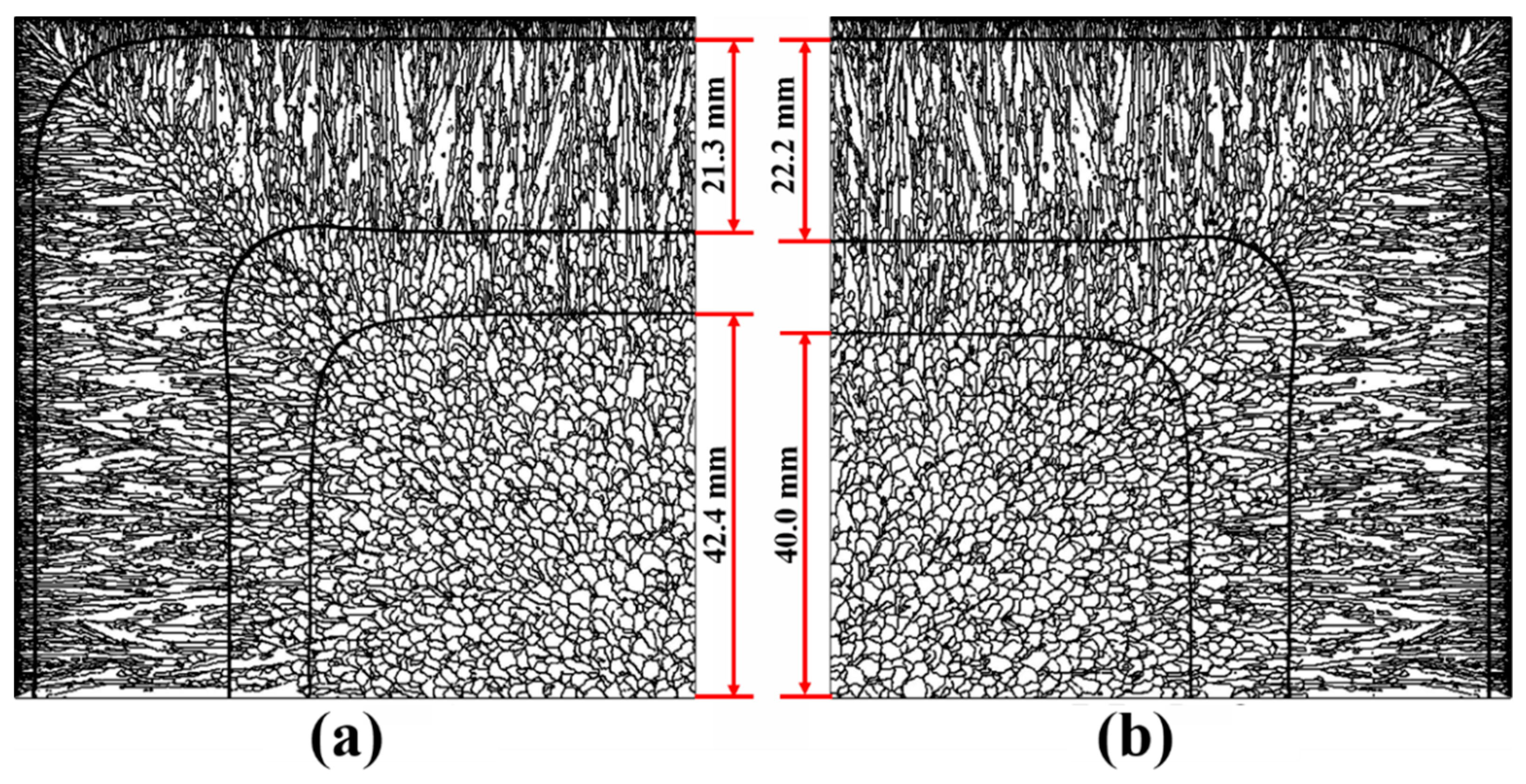
The solidification structures under the two cooling strategies were simulated using the CAFE coupling model and presented in Figure 12. Different kinds of structures are demarcated by solid lines. As seen from Figure 12, the columnar crystal zone and the mixed crystal zone of Mode 2 are longer than that of Mode 1, and the equiaxed crystal zone shows the opposite result. The columnar crystal is closely related to temperature gradient during solidification [31], and liable to grow at a big temperature gradient.
At the end of secondary cooling zone A, the temperature distribution and gradient from the billet center to surface center were calculated using the heat transfer model, as shown in Figure 13. It can be seen that there are differences between Mode 1 and Mode 2 on the temperature distribution and gradient, and the differences become unclear at the position of 30 mm from the billet center. Within the range of 30 mm to 50 mm from the billet center, where the solidification proceeds, the temperature distribution and gradient are highlighted. It can be seen that the temperature gradient of Mode 2 is bigger than that of Mode 1. Therefore, the growth of columnar crystal for Mode 2 is promoted. Consequently, the solidification structure of Mode 2 exhibits a relatively wider columnar crystal zone.
According to the solidification structures shown in Figure 12, the equiaxed crystal ratio was calculated in light of areal percentage. Meanwhile, the number of equiaxed crystal was counted to calculate the equiaxed crystal density. Table 5 shows the equiaxed crystal ratio and density of different cooling strategies. The equiaxed crystal density of Mode 2 is increased and the equiaxed crystal ratio is decreased compared with Mode 1. It indicates that the transverse non-uniform secondary cooling strategy is able to increase the compactness of central equiaxed crystal and decrease the equiaxed crystal ratio. It has been documented that the equivalent effect can be acquired by increasing the secondary cooling intensity [6,7], and that intense secondary cooling is beneficial to reducing the central segregation of high carbon steel billet with a small section size [32]. Transverse non-uniform secondary cooling strategy enhances the cooling effect using the same amount of water, and therefore shows potential to minimize the central segregation of the billet.

5.4. Summary

Table 6 summarizes the main comparative factors between transverse uniform and non-uniform secondary cooling strategies according to the above findings. Compared with transverse uniform secondary cooling strategy, the non-uniform strategy features a higher corner temperature, smaller transverse temperature difference, shorter liquid pool length, narrower central equiaxed crystal zone, and finer central equiaxed crystal of billet. These effects are beneficial to improving the surface quality and central segregation of billet. Disadvantageously, the reheating rate of the surface center is increased and may lead to reheat-type internal cracks in billet when the transverse distribution of secondary cooling water is non-uniform. In a word, the uniform cooling strategy contributes to reducing internal cracks of billet, and the non-uniform one is beneficial for surface quality and central segregation. According to the demands of different steel grades, the continuous caster can adopt a proper cooling strategy, which is associated with nozzle collocations. C80D steel has a high demand for central segregation and surface quality, but a low demand for internal cracks as the cracks can be eliminated in the rolling process. Therefore, transverse non-uniform secondary cooling strategy is a better choice for the production of C80D steel.

6. Conclusions

Water flux distributions of six spraying nozzles were measured using an apparatus. The nozzles were from two similar continuous casters. Two secondary cooling strategies were obtained, namely transverse uniform and non-uniform distribution secondary cooling strategies. A heat transfer model and a CAFE coupling model were established and assisted by the measured water flux distributions. The models were verified by comparing the surface temperature and the solidification structure to ensure their accuracy. The heat transfer and solidification structure of C80D steel billet were compared under the two cooling strategies. The following conclusions can be drawn:
  • For a single spraying nozzle, the transverse water flux distribution is non-uniform, and there is more water on the spraying center and less water on the spraying edge. However, a transverse uniform water flux distribution can be obtained in the effective range by adjusting the nozzle collocations.
  • The transverse non-uniform secondary cooling water is able to improve the cooling uniformity along the transverse direction. The corner temperature is effectively increased and the transverse temperature difference is reduced. Nevertheless, the reheating rate of the surface center is increased when the billet enters into the air-cooling zone.
  • Compared with the uniform cooling strategy, the cooling intensity of the non-uniform strategy on billet is enhanced. The shell thickness at the end of the secondary cooling zone is increased by 1.9 mm and the liquid pool length is decreased by 0.28 m.
  • The non-uniform cooling strategy promotes the growth of columnar crystal. The compactness of central equiaxed crystal is increased and the equiaxed crystal ratio is decreased. These effects are equivalent to increasing the secondary cooling intensity.
  • The non-uniform cooling strategy is beneficial to improving the surface quality, corner crack, and central segregation of billet, but may result in internal cracks. On the production of C80D steel, the non-uniform strategy is better than the uniform one.

Author Contributions

Conceptualization, Y.H. and Q.L.; data curation, Y.H. and X.W.; investigation, Y.H., X.W. and M.G.; project administration, Q.L.; validation, F.Z. and J.C.; writing—original draft, Y.H.; writing—review and editing, J.Z. and Q.L.

Funding

This research was funded by the Innovative and Entrepreneurial Talent Project in Jiangsu province, grant number 2016A426, and independent subject of State Key Laboratory of Advanced Metallurgy, University of Science and Technology Beijing, grant number 41617003.

Acknowledgments

The authors are grateful to the Innovative and Entrepreneurial Talent Project in Jiangsu province, and independent subject of State Key Laboratory of Advanced Metallurgy, University of Science and Technology Beijing, China, which enabled the research to be carried out successfully.

Conflicts of Interest

The authors declare no conflicts of interest.

References

  1. Flesch, R.; Bleck, W. Crack susceptibility of medium and high alloyed tool steels under continuous casting conditions. Steel Res. 1998, 69, 292–299. [Google Scholar] [CrossRef]
  2. Han, Z.; Cai, K.; Liu, B. Prediction and analysis on formation of internal cracks in continuously cast slabs by mathematical models. ISIJ Int. 2001, 41, 1473–1480. [Google Scholar] [CrossRef]
  3. Lu, Y.J.; Wang, Q.; Li, Y.G.; He, S.P.; He, Y.M.; Pan, S.S.; Zhang, J.G.; Hu, B. Prevention of transverse corner cracks in continuously cast steel slabs using asymmetric secondary cooling nozzle. Ironmak. Steelmak. 2011, 38, 561–565. [Google Scholar] [CrossRef]
  4. Raihle, C.; Fredriksson, H. On the formation of pipes and centerline segregates in continuously cast billets. Metall. Mat. Trans. B 1994, 25, 123–133. [Google Scholar] [CrossRef]
  5. De Toledo, G.; Lainez, J.; Cirión, J. Model optimization of continuous casting steel secondary cooling. Mater. Sci. Eng. A 1993, 173, 287–291. [Google Scholar] [CrossRef]
  6. Zeng, J.; Chen, W. Effect of secondary cooling conditions on solidification structure and central macrosegregation in continuously cast high-carbon rectangular billet. High Temp. Mater. Processes 2015, 34, 577–583. [Google Scholar] [CrossRef]
  7. Dou, K.; Yang, Z.; Liu, Q.; Huang, Y.; Dong, H. Influence of secondary cooling mode on solidification structure and macro-segregation behavior for high-carbon continuous casting bloom. High Temp. Mater. Process. 2017, 36, 741–753. [Google Scholar] [CrossRef]
  8. Camisani-Calzolari, F.; Craig, I.; Pistorius, P. Speed disturbance compenation in the secondary cooling zone in continuous casting. ISIJ Int. 2000, 40, 469–477. [Google Scholar] [CrossRef]
  9. Zhang, J.; Chen, D.; Wang, S.; Long, M. Compensation control model of superheat and cooling water temperature for secondary cooling of continuous casting. Steel Res. Int. 2011, 82, 213–221. [Google Scholar] [CrossRef]
  10. Long, M.; Chen, D.; Zhang, L.; Zhao, Y.; Liu, Q. A mathematical model for mitigating centerline macro segregation in continuous casting slab. Met. Int. 2011, 16, 19–33. [Google Scholar]
  11. Shen, H.; Hardin, R.; MacKenzie, R.; Beckermann, C. Simulation using realistic spray cooling for the continuous casting of multi-component steel. J. Mater. Sci. Technol. 2002, 18, 311–314. [Google Scholar]
  12. Ramstorfer, F.; Roland, J.; Chimani, C.; Mörwald, K. Investigation of spray cooling heat transfer for continuous slab casting. Mater. Manuf. Process. 2011, 26, 165–168. [Google Scholar] [CrossRef]
  13. Ji, C.; Luo, S.; Zhu, M.; Sahai, Y. Uneven solidification during wide-thick slab continuous casting process and its influence on soft reduction zone. ISIJ Int. 2014, 54, 103–111. [Google Scholar] [CrossRef]
  14. Wang, X.; Liu, Q.; Wang, B.; Wang, X.; Qing, J.-S.; Hu, Z.-G.; Sun, Y.H. Optimal control of secondary cooling for medium thickness slab continuous casting. Ironmak. Steelmak. 2011, 38, 552–560. [Google Scholar] [CrossRef]
  15. Long, M.; Chen, D. Study on Mitigating center macro-segregation during steel continuous casting process. Steel Res. Int. 2011, 82, 847–856. [Google Scholar] [CrossRef]
  16. Ma, J.; Xie, Z.; Jia, G. Applying of real-time heat transfer and solidification model on the dynamic control system of billet continuous casting. ISIJ Int. 2008, 48, 1722–1727. [Google Scholar] [CrossRef]
  17. Hou, Z.; Jiang, F.; Cheng, G. Solidification structure and compactness degree of central equiaxed grain zone in continuous casting billet using cellular automaton-finite element method. ISIJ Int. 2012, 52, 1301–1309. [Google Scholar] [CrossRef]
  18. Ma, J.; Wang, B.; Zhang, D.; Song, W. Optimization of secondary cooling water distribution for improving the billet quality for a small caster. ISIJ Int. 2018, 58, 915–920. [Google Scholar] [CrossRef]
  19. Assuncao, C.; Tavares, R.; Oliveira, G. Comparison of uniform and non-uniform water flux density approaches applied on a mathematical model of heat transfer and solidification for a continuous casting of round billets. Metall. Mat. Trans. B 2015, 46, 366–377. [Google Scholar] [CrossRef]
  20. Choudhary, S.; Mazumdar, D. Mathematical modelling of fluid flow, heat transfer and solidification phenomena in continuous casting of steel. Steel Res. Int. 1995, 66, 199–205. [Google Scholar] [CrossRef]
  21. Cai, K.; Yang, J. Investigation of Heat Transfer in the Spray Cooling of Continuous Casting. J. Univ. Sci. Technol. Beijing 1989, 11, 510–515. [Google Scholar]
  22. Nozaki, T.; Matsuno, J.; Murata, K.; Ooi, H.; Kodama, M. A secondary cooling pattern for preventing surface cracks of continuous casting slab. Trans. Iron Steel Inst. Jpn. 1978, 18, 330–338. [Google Scholar]
  23. Thevoz, P.; Desbiolles, J.; Rappaz, M. Modeling of equiaxed microstructure formation in casting. Metall. Trans. A 1989, 20, 311–322. [Google Scholar] [CrossRef]
  24. Kurz, W.; Giovanola, B.; Trivedi, R. Theory of microstructural development during rapid solidification. Acta Metall. 1986, 34, 823–830. [Google Scholar] [CrossRef]
  25. Kurz, W.; Trivedi, R. Solidification microstructures: Recent developments and future directions. Acta Metall. 1990, 38, 1–17. [Google Scholar] [CrossRef]
  26. Cornelissen, M. Mathematical-model for solidification of multicomponent alloys. Ironmak. Steelmak. 1986, 13, 204–212. [Google Scholar]
  27. Jing, C.; Wang, X.; Jiang, M. Study on solidification structure of wheel steel round billet using FE-CA coupling model. Steel Res. Int. 2011, 82, 1173–1179. [Google Scholar] [CrossRef]
  28. Yamazaki, M.; Natsume, Y.; Harada, H.; Ohsasa, K. Numerical simulation of solidification structure formation during continuous casting in Fe–0.7 mass% C alloy using cellular automaton method. ISIJ Int. 2006, 46, 903–908. [Google Scholar] [CrossRef]
  29. Brimacombe, J.; Sorimachi, K. Crack formation in the continuous casting of steel. Metall. Trans. B 1977, 8, 489–505. [Google Scholar] [CrossRef]
  30. Kulkarni, M.; Subash Babu, A. Optimization of continuous casting using simulation. Mater. Manuf. Process. 2005, 20, 595–606. [Google Scholar] [CrossRef]
  31. M’Hamdi, M.; Combeau, H.; Lesoult, G. Modelling of heat transfer coupled with columnar dendritic growth in continuous casting of steel. Int. J. Numer. Methods Heat Fluid Flow 1999, 9, 296–317. [Google Scholar] [CrossRef]
  32. Ludlow, V.; Normanton, A.; Anderson, A.; Thiele, M.; Ciriza, J.; Laraudogoitia, J.; Knoop, W. Strategy to minimise central segregation in high carbon steel grades during billet casting. Ironmak. Steelmak. 2005, 32, 68–74. [Google Scholar] [CrossRef]
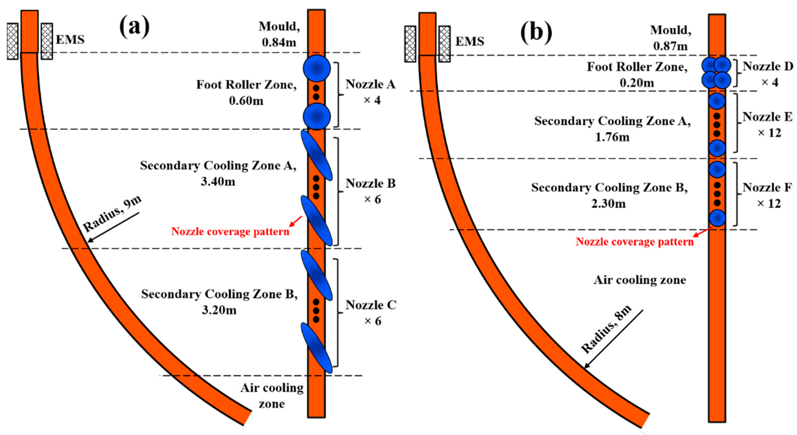
Figure 1. Schematic diagrams of continuous casters and nozzle arrangements: (a) Caster 1; (b) Caster 2.
Metals 09 00543 g001
Figure 2. Schematic diagram of experimental apparatus.
Metals 09 00543 g002
Figure 3. Water flux distributions of spraying nozzles under specific collocations.
Metals 09 00543 g003
Figure 4. Schematic diagram of water flux distribution in the foot-roller zone and secondary cooling zone during continuous casting: (a) Mode 1; (b) Mode 2.
Metals 09 00543 g004
Figure 5. Calculated thermo-physical properties of C80D steel, (a) solid fraction, (b) density and enthalpy, and (c) thermal conductivity.
Metals 09 00543 g005
Figure 6. Temperature profiles of surface center.
Metals 09 00543 g006
Figure 7. Comparison of (a) actual solidification structure and (b) simulated solidification structure.
Metals 09 00543 g007
Figure 8. Temperature variations of the billet surface during continuous casting: (a) Mode 1; (b) Mode 2.
Metals 09 00543 g008
Figure 9. Temperature variations of the billet center, surface center, and billet corner: (a) Mode 1; (b) Mode 2.
Metals 09 00543 g009
Figure 10. Temperature distributions of one-fourth cross section at various positions.
Metals 09 00543 g010
Figure 11. Internal temperature distribution from meniscus to air-cooling zone: (a) Mode 1; (b) Mode 2.
Metals 09 00543 g011
Figure 12. Simulated solidification structure of one-fourth cross section: (a) Mode 1; (b) Mode 2.
Metals 09 00543 g012
Figure 13. Calculated temperature (a) variation and (b) gradient from the billet center to surface center at the end of secondary cooling zone A.
Metals 09 00543 g013
Table 1. Main parameters of spraying nozzles.
NozzleType numberJet typePressure/MPaJet Distance/mmSpraying Angle
Nozzle ACONCAST 7565LFull cone0.5230060.4°
Nozzle BCONCAST RE2-8-80/28Flat0.5230087.6°/26.4°
Nozzle CCONCAST RE1-4-80/28Flat0.5230082.4°/28.4°
Nozzle DZY3/8PZ72667QZ1Full cone0.4012561.6°
Nozzle E3665Full cone0.8012553.1°
Nozzle F2265Full cone0.6012553.5°
Table 2. Water flow rates, boundary conditions, and calculated formulae of different cooling zones.
ZoneWater Flow Rate, m3/hBoundary ConditionCalculated Formula
Mold113 q m q m = 2680000 β t
Foot-roller zone8.06 q f = h f ( T T f ) h f = 480 ( W / 60 ) 0.351
Secondary cooling zone A12.96 q s = h s ( T T s ) h s = 1570 W 0.55 ( 1 0.0075 T s ) / 2.16
Secondary cooling zone B5.76 q s = h s ( T T s ) h s = 1570 W 0.55 ( 1 0.0075 T s ) / 2.16
Air-cooling zone- q a = σ ε ( T 4 T a 4 ) σ = 5.67 × 10 8 , ε = 0.8
Table 3. Chemical composition of C80D steel and related parameters.
CompositionCSiMnPS
Mass fraction, %0.820.200.730.0170.004
Partition coefficient, k00.350.520.750.060.025
Liquidus slope, m−60−8−5−34−40
Diffusivity in liquid, D, m2/s2.0 × 10−82.4 × 10−92.0 × 10−84.7 × 10−94.5 × 10−9
Table 4. Casting parameters used for C80D steel billet.
ItemValue
Casting speed2.4 m/min
Pouring temperature1485 °C
Superheat15 °C
Water flux of mold cooling113 m3/h
Temperature difference between inlet and outlet of mold water7.9 °C
Ambient temperature25 °C
Table 5. Equiaxed crystal ratio and density of different cooling strategies.
Cooling StrategyEquiaxed Crystal DensityEquiaxed Crystal Ratio
Mode 10.83 /mm232.0%
Mode 20.89 /mm228.4%
Table 6. Main comparative factors between transverse uniform and non-uniform secondary cooling strategies.
ItemUniformNon-Uniform
Transverse temperature difference in the secondary cooling zone, °C356174
Corner temperature at straightening point, °C760792
Maximum reheating rate of surface center, °C/m95138
Maximum reheating rate of billet corner, °C/m11473
Liquid pool length, m10.6010.32
Equiaxed crystal density, /mm20.830.89
Equiaxed crystal ratio, %32.028.4