Numerical Analysis of the Perforated Steel Sheets Under Uni-Axial Tensile Force


Abstract
:1. Introduction
2. Research Methodology
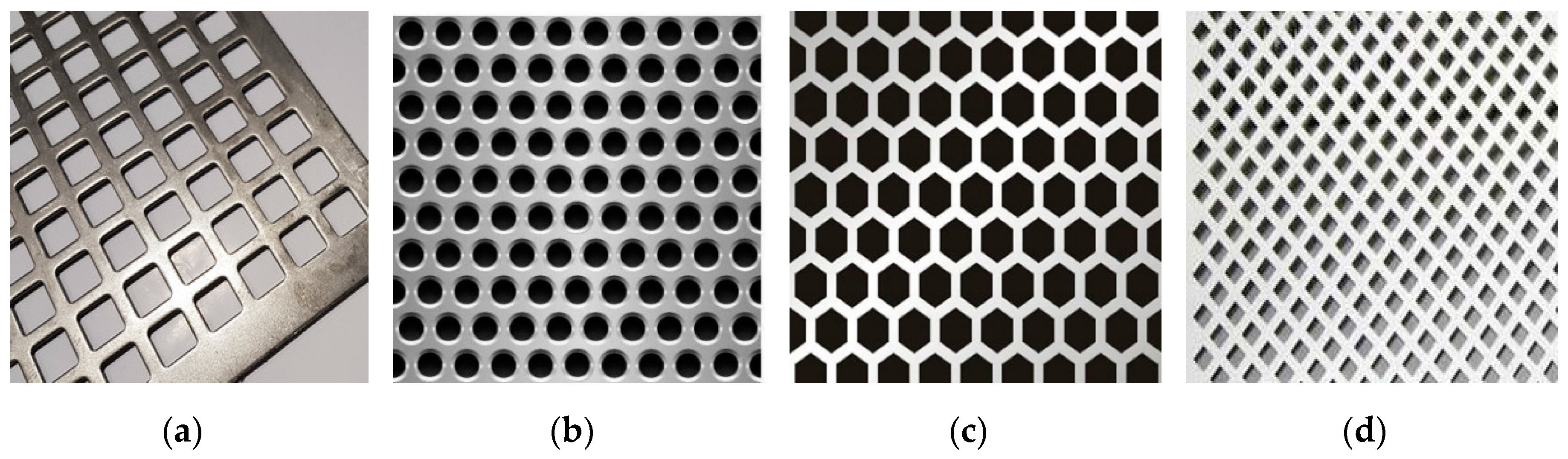
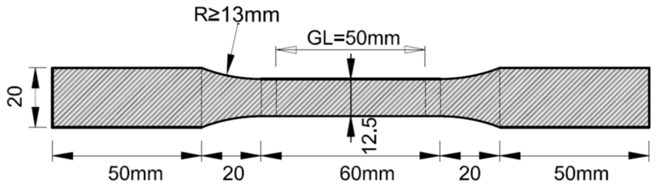
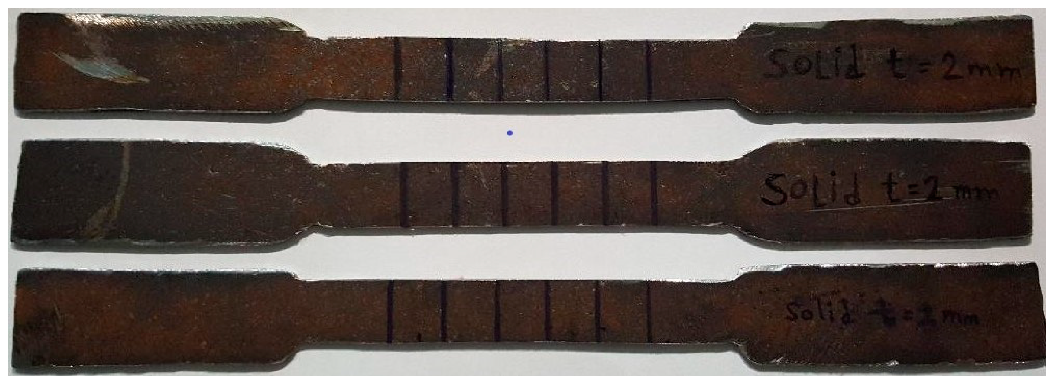
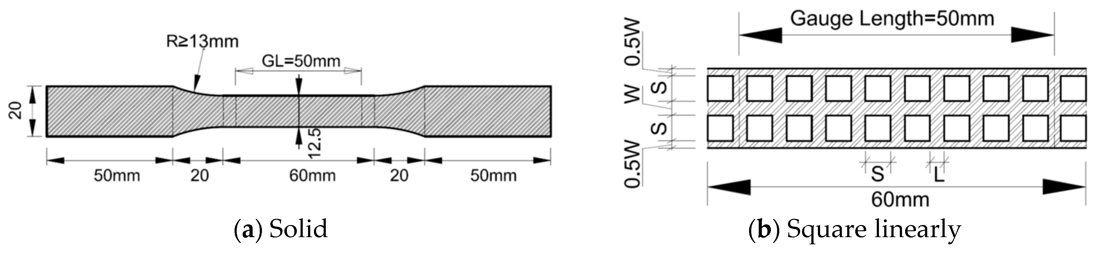
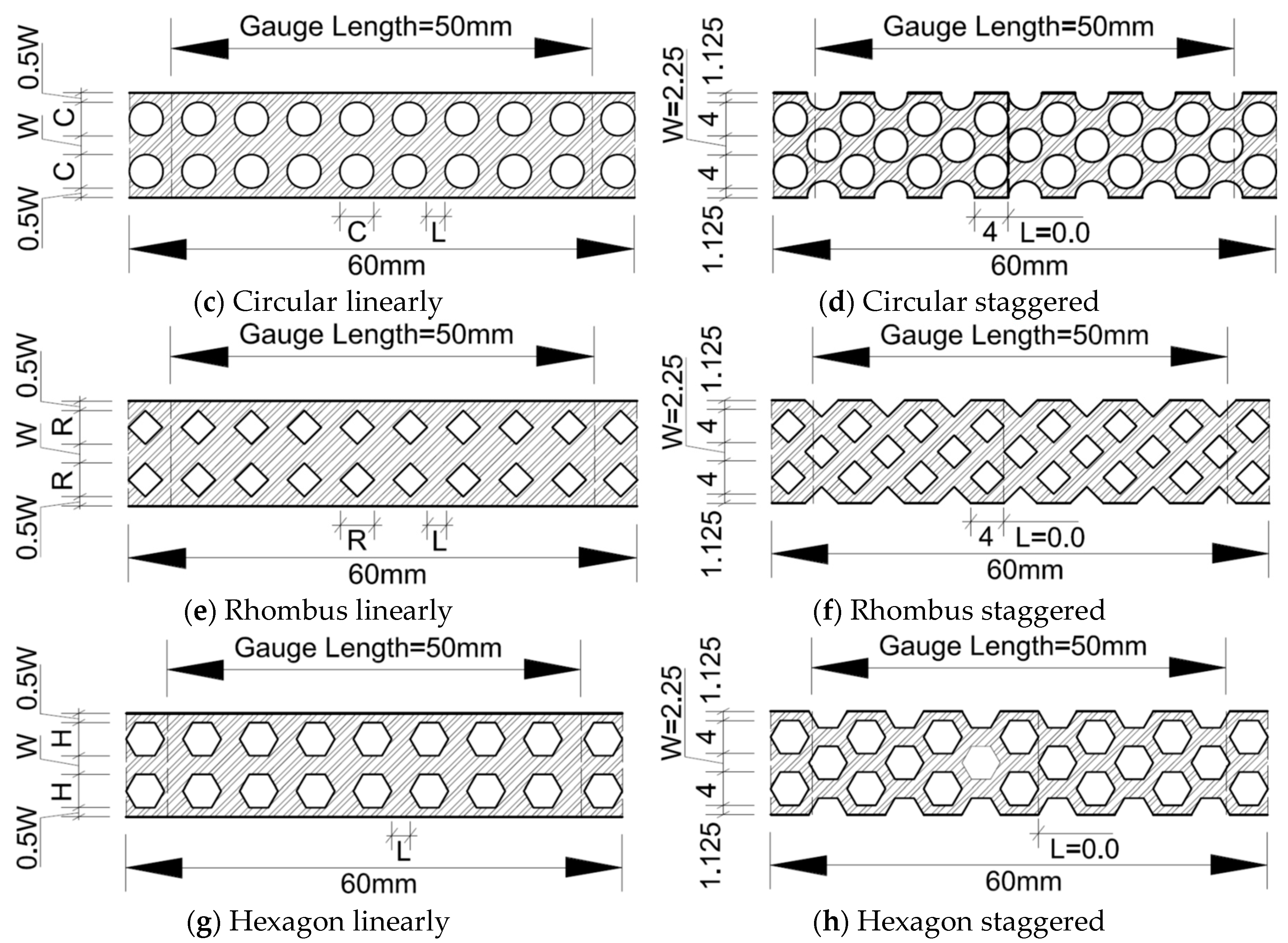
2.1. Experimental Test Specimens
2.2. Numerical Test Specimens
2.2.1. ANSYS Finite Element Model Study: Steel Sheet Modeling Characteristics
2.2.2. Numerical Model Studies
3. Experimental and Numerical Results and Discussion
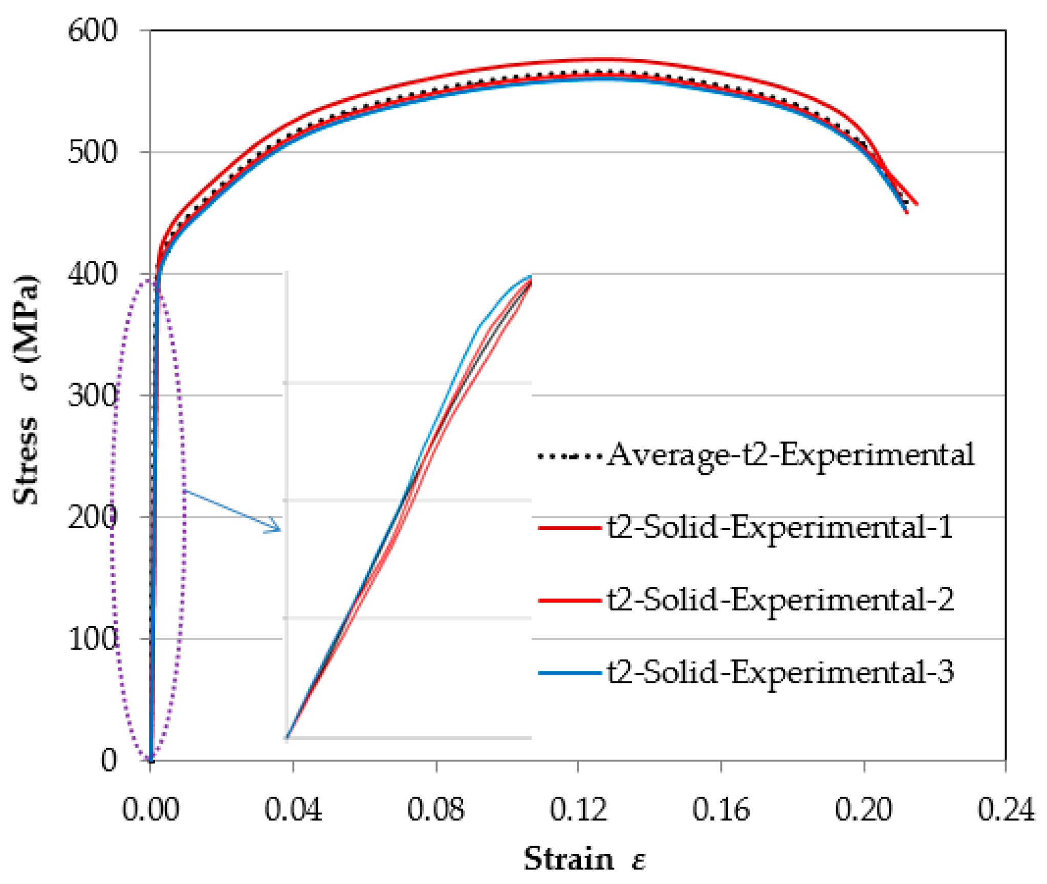
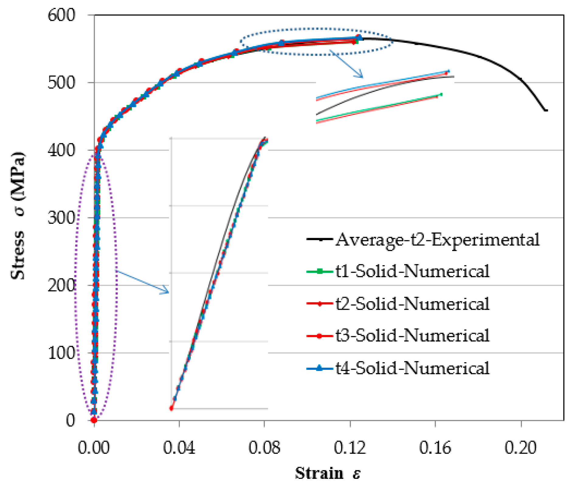
3.1. Experimental Results and Comparison with FE Analysis
3.2. Comparison of Different Perforated and Solid Steel Sheets based on FE Analysis
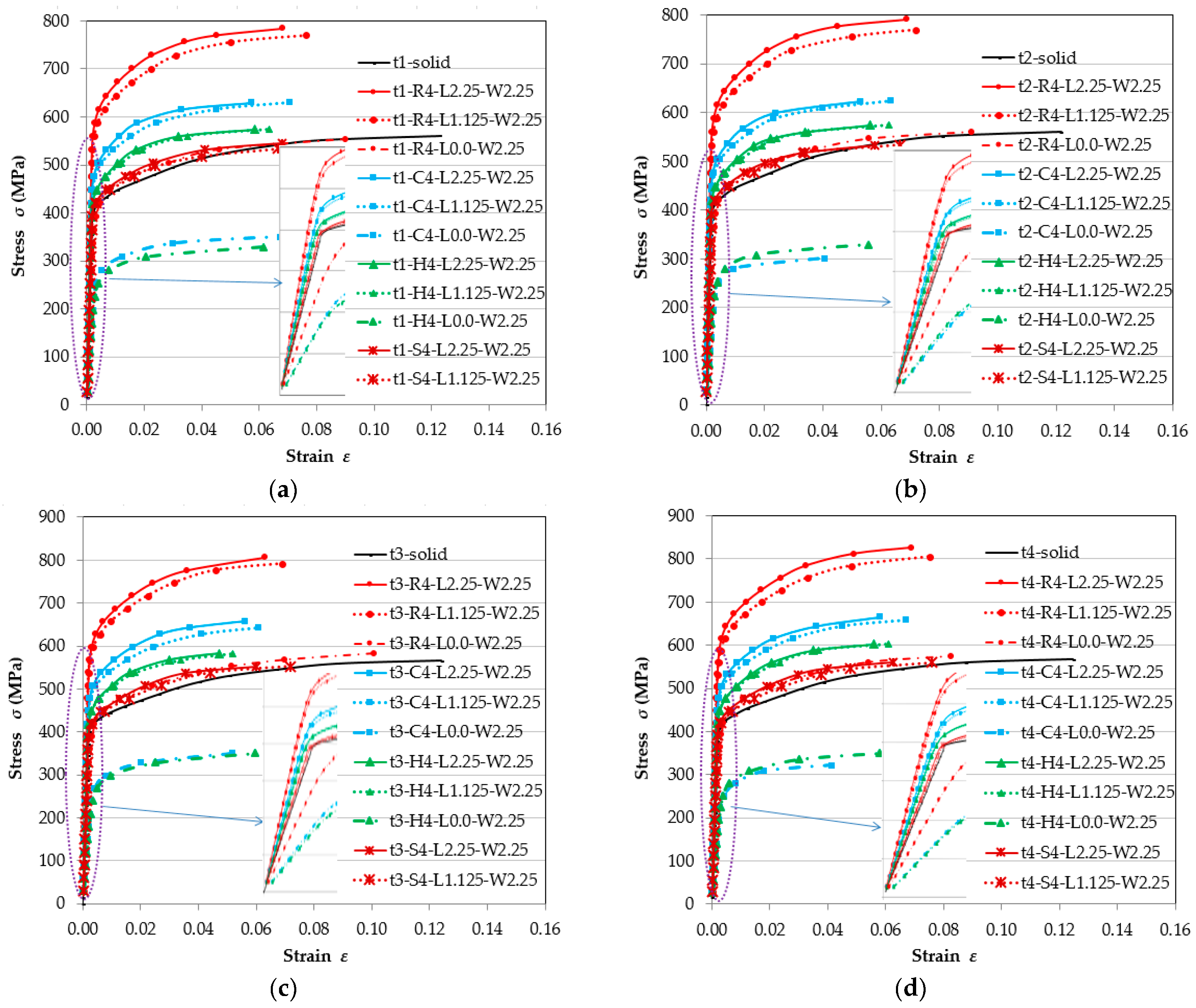
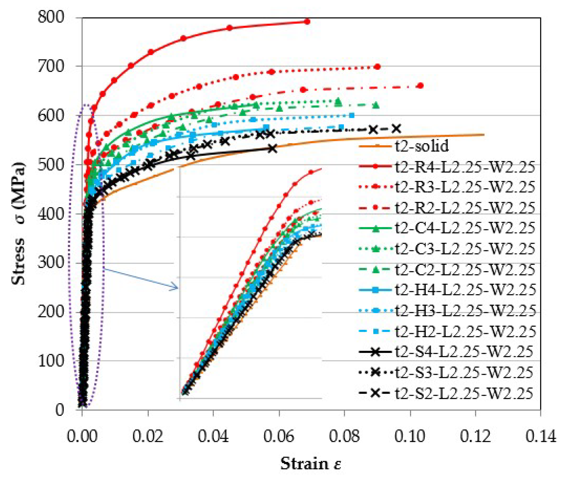
3.2.1. Stress-Strain Engineering Relationships
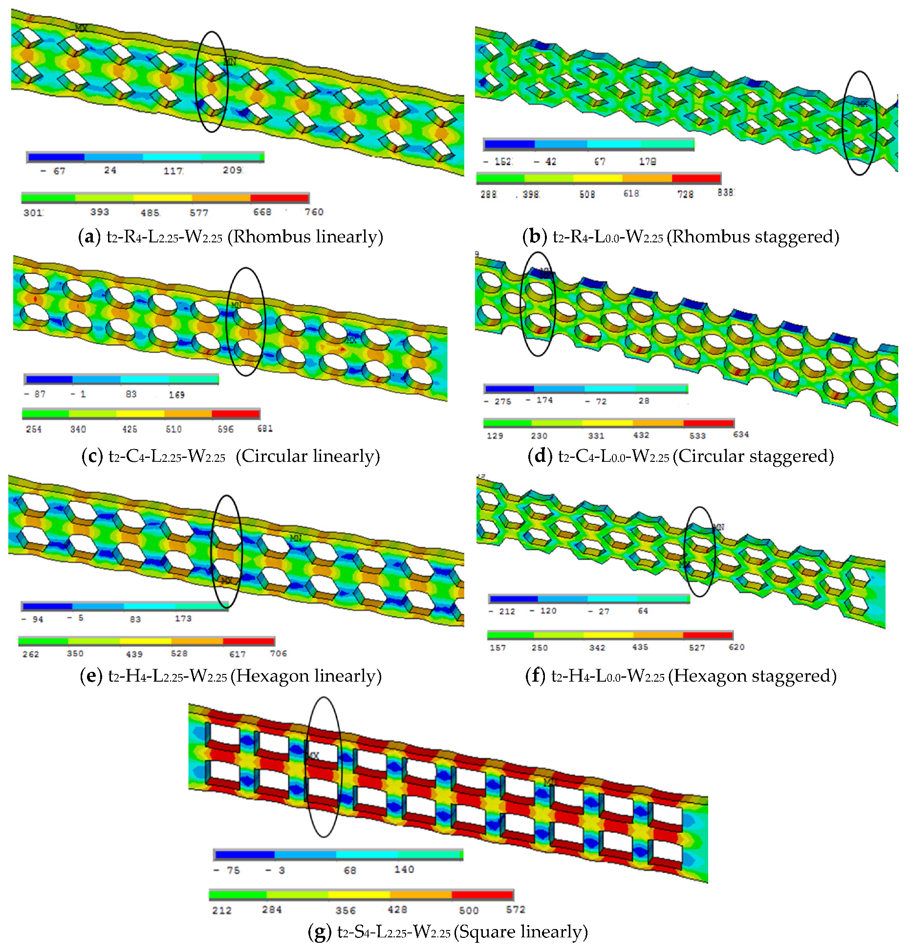
3.2.2. Pattern of Maximum Ultimate Stresses
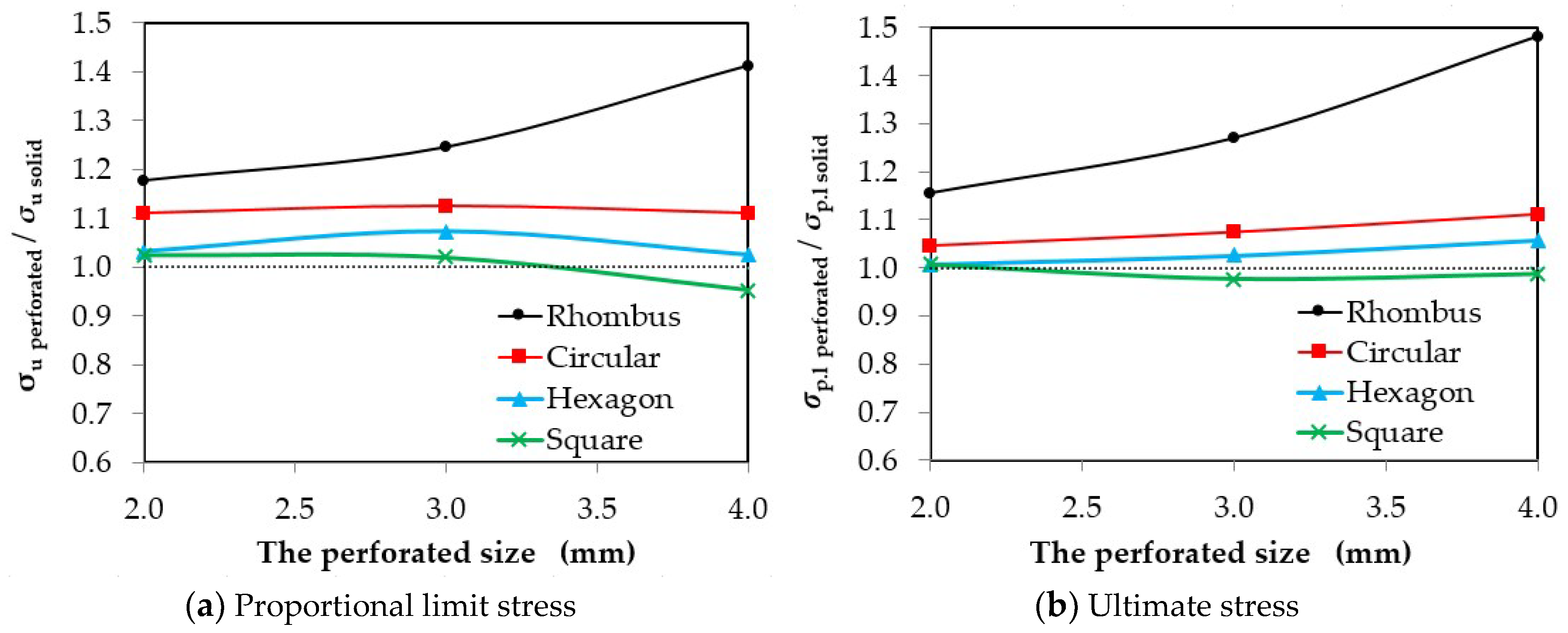
3.2.3. Influence of the Perforated Sizes
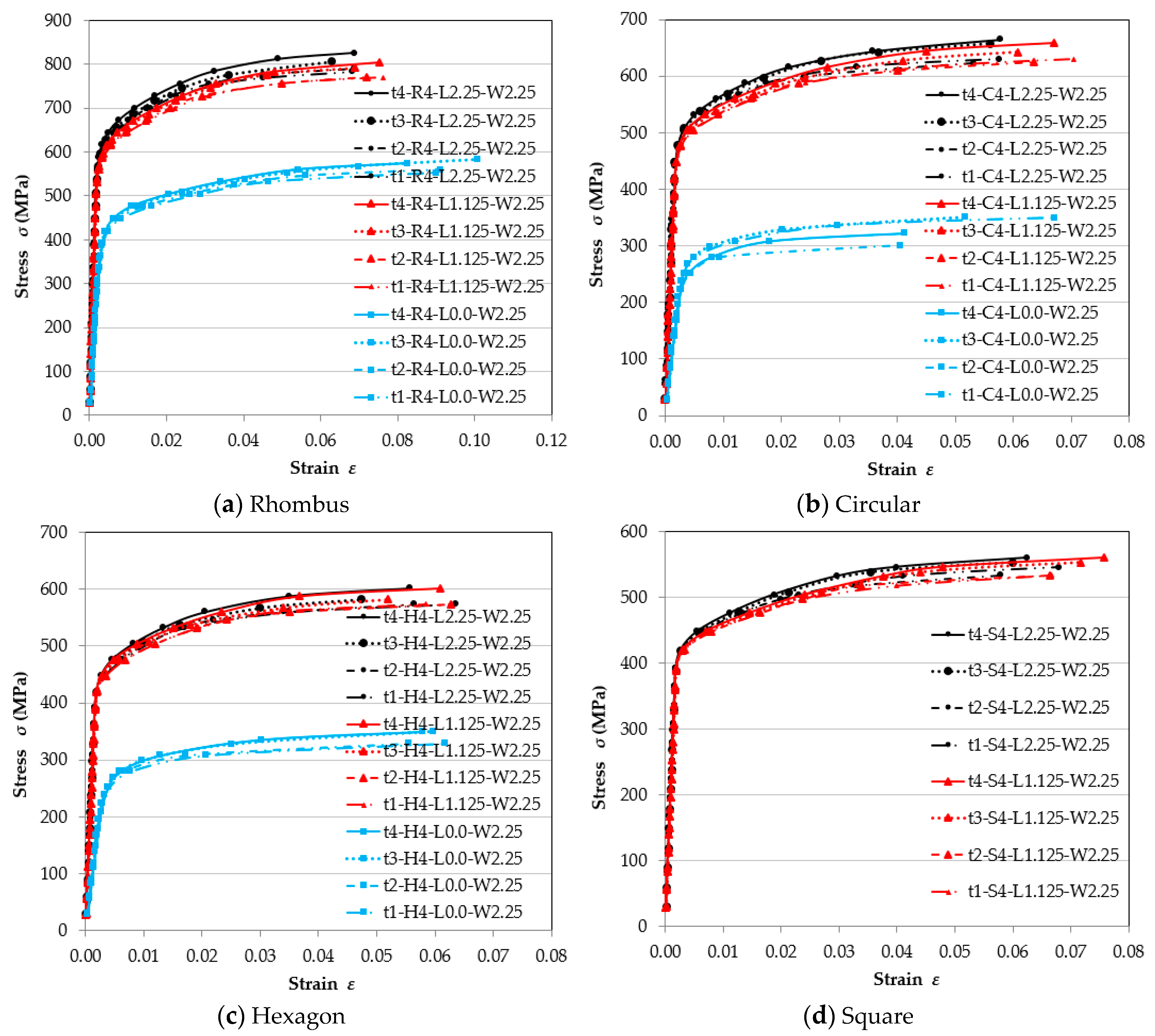
3.2.4. Influence of the Perforated Steel Sheets Thicknesses
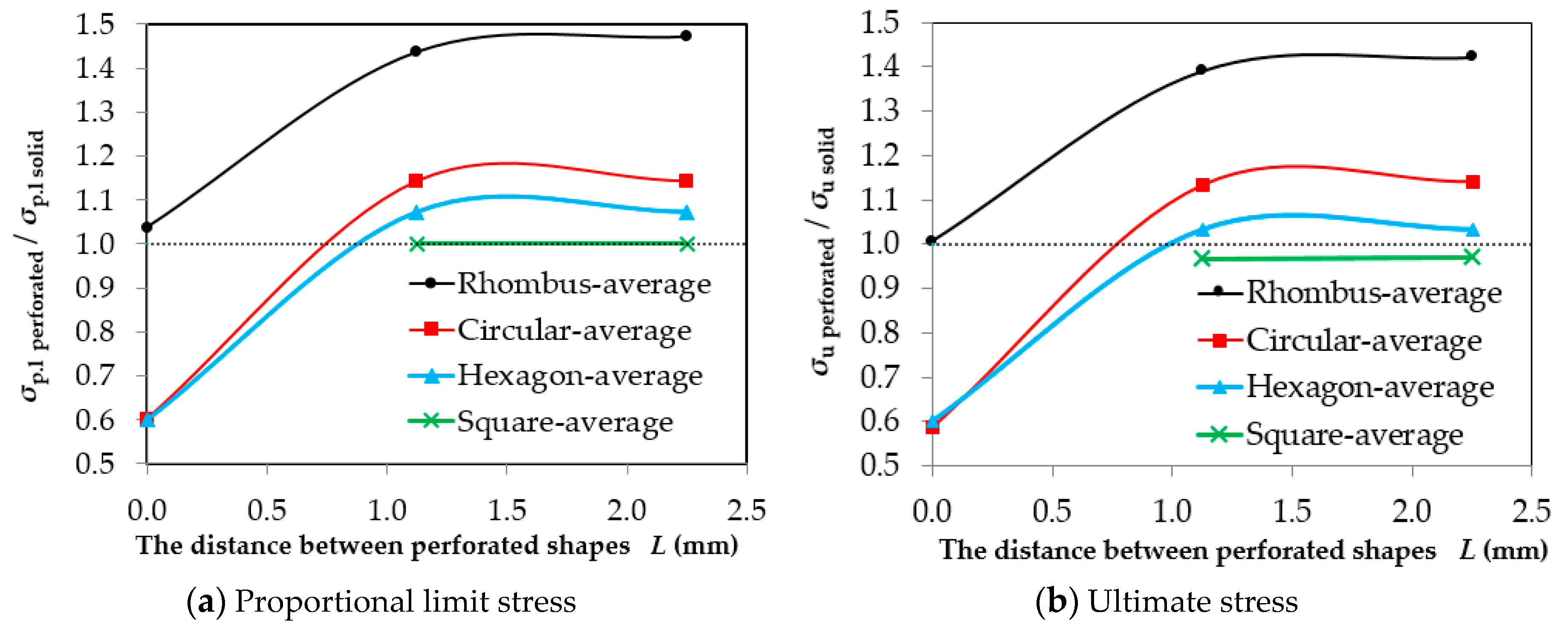
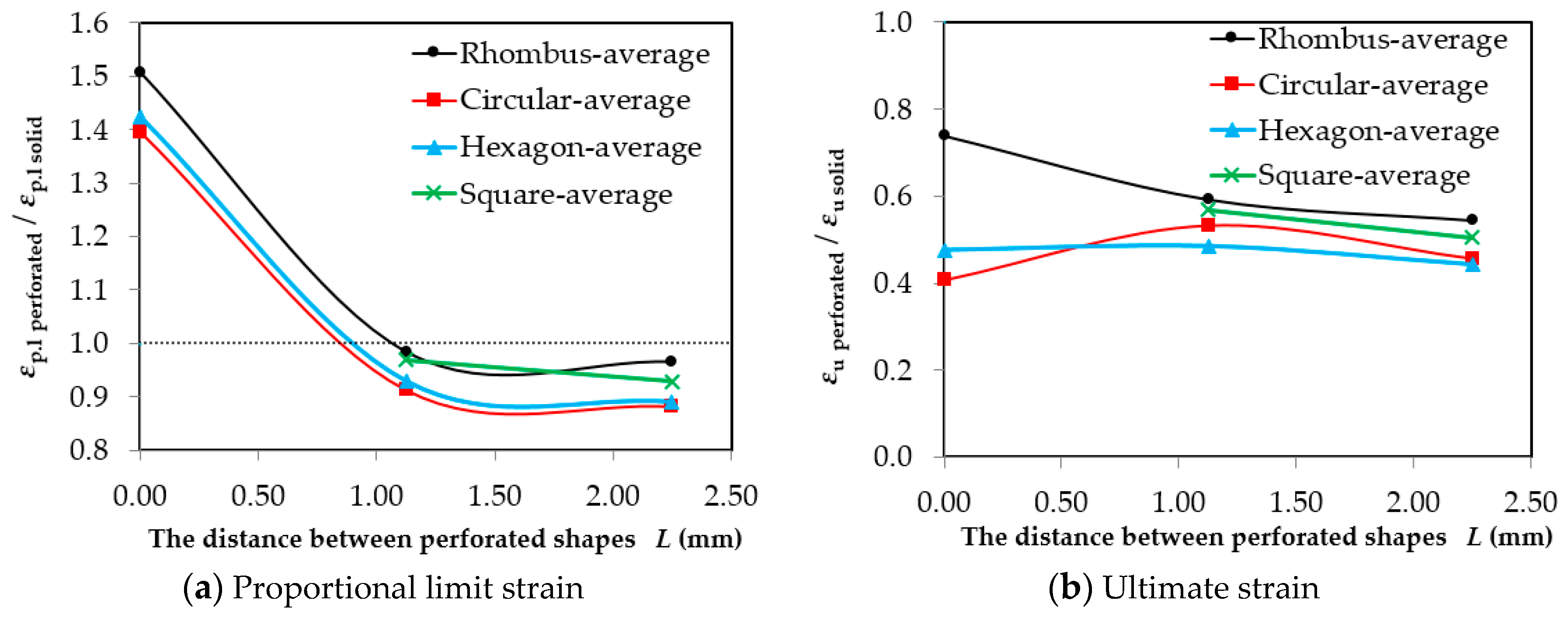
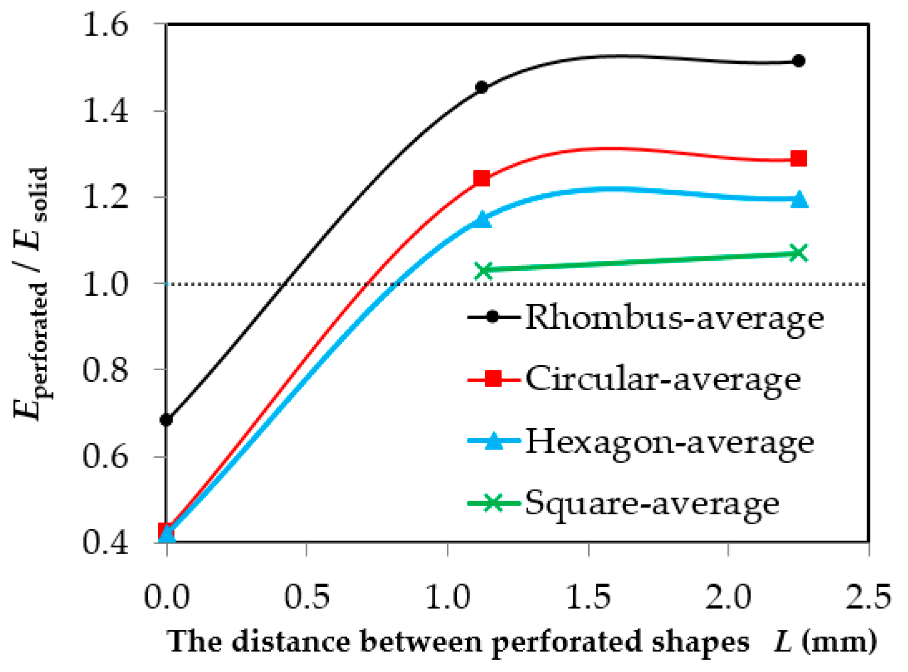
3.2.5. Influence of the Distance between Perforated Shapes
- For stresses: The results obtained indicate that the effect of the perforated staggered shape on the stresses has the opposite effect, as it reduces the stress and the percentage of the decrease in the amount of stresses from the control specimen was measured and found that for the circular and hexagon shapes, the average proportional limit stresses are 60.1% and 60.1%, respectively, while the average ultimate stresses are 58.7% and 60.3%, respectively. However, it was observed in the perforated rhombus shape that the ratio was not less than the control specimen but did not improve the properties of the steel sheet where the ratios were found to be 103.8% and 100.6% for the average proportional limit and ultimate stresses, respectively.
- For strain: The results obtained indicate that the effect of the perforated staggered shape on the proportional limit strains has a positive effect, as it increases the strain and the percentage of the increase in the amount of strain from the control specimen was measured and found for the rhombus, circular and hexagon shapes, which showed average proportional limit strains of 150.8%, 139.6%, and 142.5% respectively. However, it was observed that the ultimate strains have the opposite effect as it reduces the strain. The percentage of the decrease in the amount of strain from the control specimen was measured and found for the rhombus, circular and hexagon shapes, where the average proportional limit strains are 73.9%, 40.7%, and 47.6% respectively.
- For the modulus of elasticity: The results obtained indicate that the effect of the perforated staggered shape on the modulus of elasticity has the opposite effect, as it reduces the modulus of elasticity. The percentage of the average decrease in the amount of the modulus of elasticity from the control specimen was measured and found for the rhombus, circular and hexagon shapes to be 68.3%, 42.8%, and 42.1% respectively.
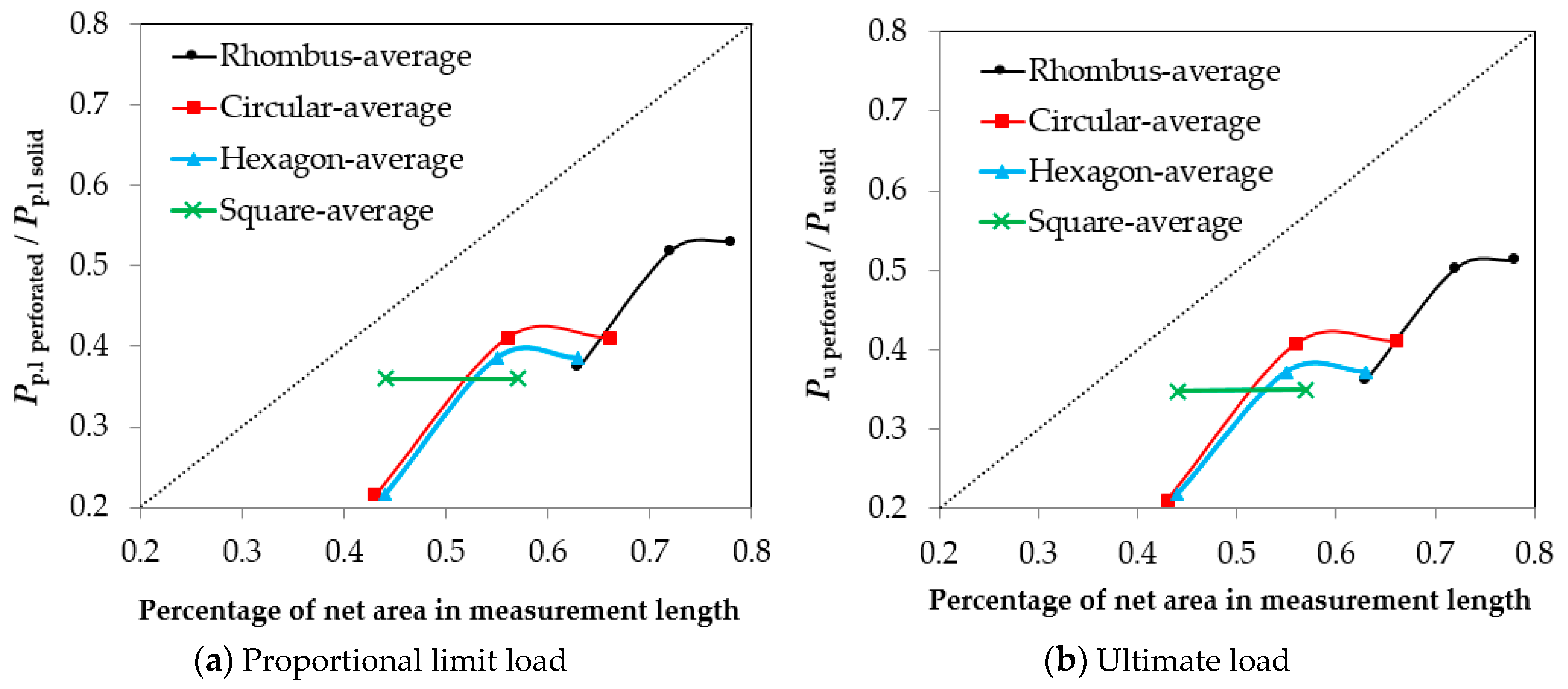
3.2.6. The Efficiency of the Perforated Shapes with the Actual Net Area
4. Conclusions
- After making a comparison with the experimental tests, the FE model is regarded as being more precise for predicting the stress-strain engineering relationships. The mean values of the proportional limit stress σpl Exp./σpl.FE is 1.02 and the modulus of elasticity EExp./E.FE is 1.00, the ultimate stress σu. Exp./σu.FE is 1.003 and the ultimate strain εu. Exp./εu.FE is 1.016.
- The effect of the perforated staggered shape on the stresses and modulus of elasticity has the opposite effect as it reduces the stress and modulus of elasticity.
- As for the shapes of the linear distribution, the effect of the distance between the shapes was not significant and almost was nonexistent.
- In the first place, the paper finds that the perforated rhombus shape has the biggest effect on stress-strain engineering relationships. In the second place, it finds that perforated circular and hexagon shapes have an effect on stress-strain engineering relationships. But in perforated square sizes, it finds that there is no observed difference in the proportional limit stress, and for ultimate stress, it gives the opposite effect.
- The efficiency of the perforated staggered or linearly distribution shapes with the actual net area on the applied loads has the opposite effect, as it reduces the load capacity for all types of perforated shapes. Despite the decrease in load capacity, the efficiency of the perforated staggered or linearly distribution improves the properties of the steel sheets.
Funding
Acknowledgments
Conflicts of Interest
Abbreviations
| σE | Engineering stress |
| εE | Engineering strain |
| P | Axial tensile applied load |
| A0 | Original area cross section |
| L0 | Original Length |
| ∆L | Elongation increasing in original length |
| R | Rhombus perforated |
| C | Circular perforated |
| H | Hexagon perforated |
| S | Square perforated |
| σy | Yield strength, |
| σu | Ultimate strength |
| E | Initial elastic modulus |
| σpl | Proportional limit stress |
| εu | Ultimate strain |
| εpl | Proportional limit strain |
References
- American Society for Testing and Materials (ASTM). ASTM Standards A370-08a: Standard Test Methods and Definitions for Mechanical Testing of Steel Products; American Society for Testing and Materials: West Conshohocken, PA, USA, 2008. [Google Scholar] [CrossRef]
- Arasaratnam, P.; Sivakumaran, K.S.; Tait, M.J. True stress-true strain models for structural steel elements. ISRN Civ. Eng. 2011, 2011, 11. [Google Scholar] [CrossRef]
- Faridmehr, I.; Osman, M.H.; Adnan, A.B.; Nejad, A.F.; Hodjati, R.; Azimi, M.A. Correlation between engineering stress-strain and true stress-strain curve. Am. J. Civ. Eng. Archit. 2014, 2, 53–59. [Google Scholar] [CrossRef]
- Kweon, H.D.; Heo, E.J.; Lee, D.H.; Kim, J.W. A methodology for determining the true stress-strain curve of SA-508 low alloy steel from a tensile test with finite element analysis. J. Mech. Sci. Technol. 2018, 32, 3137–3143. [Google Scholar] [CrossRef]
- Galambos, T.V. Guide to Stability Design Criteria for Metal Structures, 5th ed.; John Wiley & Sons: New York, NY, USA, 1998. [Google Scholar]
- Beygelzimer, Y.; Estrin, Y.; Kulagin, R. Synthesis of Hybrid Materials by Severe Plastic Deformation: A New Paradigm of SPD Processing. Adv. Eng. Mater. 2015, 17, 1853–1861. [Google Scholar] [CrossRef]
- Andh, U.B.; Chavan, S.M.; Kulakrni, S.G. Stress analysis of perforated plates under uniaxial compression using experimentation and finite element analysis. Int. J. Curr. Eng. Technol. 2017, 7, 431–437. [Google Scholar]
- Saroha, M. Analyse the stress concentration effect of a perforated plate under uniaxial loading using ansys. Int. J. All Res. Educ. Sci. Methods 2017, 5, 8–16. [Google Scholar]
- Saraçoğlu, M.H.; Albayrak, U. Linear static analysis of perforated plates with round and staggered holes under their self-weights. Res. Eng. Struct. Mater. 2015, 2, 39–47. [Google Scholar] [CrossRef]
- Maiorana, E.; Pellegrino, C.; Modena, C. Linear buckling analysis of perforated plates subjected to localised symmetrical load. Eng. Struct. 2008, 30, 3151–3158. [Google Scholar] [CrossRef]
- Ndubuaku, O.; Liu, X.; Martens, M.; Cheng, J.J.R.; Adeeb, S. The effect of material stress-strain characteristics on the ultimate stress and critical buckling strain of flat plates subjected to uniform axial compression. Constr. Build. Mater. 2018, 182, 346–359. [Google Scholar] [CrossRef]
- Lee, Y.C.; Chen, F.K. Yield criterion for a perforated sheet with a uniform triangular pattern of round holes and a low ligament ratio. J. Mater. Process. Technol. 2000, 103, 353–361. [Google Scholar] [CrossRef]
- American Society for Testing and Materials (ASTM). ASTM A370/ASME SA-370: Standard Test Methods and Definitions for Mechanical Testing of Steel Products; American Society for Testing and Materials: West Conshohocken, PA, USA, 2016. [Google Scholar] [CrossRef]
- Sayed, A.M.; Diab, H.M. Modeling of the Axial Load Capacity of RC Columns Strengthened with Steel Jacketing under Preloading Based on FE Simulation. Model. Simul. Eng. 2019, 2019, 8. [Google Scholar] [CrossRef]
- Seif, M.; Main, J.; Weigand, J.; McAllister, T.P.; Luecke, W. Finite element modeling of structural steel component failure at elevated temperatures. Structures 2016, 6, 134–145. [Google Scholar] [CrossRef]
- ANSYS User’s Manual; Version (15); Swanson Analysis Systems, Inc.: Cannonsburg, PA, USA, 2015.


| Steel Sheet Specimen | Steel Sheets Characteristics | Offset from Edge to Edge | |||
|---|---|---|---|---|---|
| Thickness (mm) | Perforated Type | Perforated Size (mm) | Longitudinal (mm) | Width (mm) | |
| t1-Soild | 1.00 | Control-Without | - | - | - |
| t1-R4-L2.25-W2.25 | 1.00 | Rhombus | 4.00 | 2.25 | 2.25 |
| t1-R4-L1.125-W2.25 | 1.00 | Rhombus | 4.00 | 1.125 | 2.25 |
| t1-R4-L0.0-W2.25 | 1.00 | Rhombus | 4.00 | 0.00 | 2.25 |
| t1-C4-L2.25-W2.25 | 1.00 | Circular | 4.00 | 2.25 | 2.25 |
| t1-C4-L1.125-W2.25 | 1.00 | Circular | 4.00 | 1.125 | 2.25 |
| t1-C4-L0.0-W2.25 | 1.00 | Circular | 4.00 | 0.00 | 2.25 |
| t1-H4-L2.25-W2.25 | 1.00 | Hexagon | 4.00 | 2.25 | 2.25 |
| t1-H4-L1.125-W2.25 | 1.00 | Hexagon | 4.00 | 1.125 | 2.25 |
| t1-H4-L0.0-W2.25 | 1.00 | Hexagon | 4.00 | 0.00 | 2.25 |
| t1-S4-L2.25-W2.25 | 1.00 | Square | 4.00 | 2.25 | 2.25 |
| t1-S4-L1.125-W2.25 | 1.00 | Square | 4.00 | 1.125 | 2.25 |
| t2-Soild | 2.00 | Control-Without | - | - | - |
| t2-R4-L2.25-W2.25 | 2.00 | Rhombus | 4.00 | 2.25 | 2.25 |
| t2-R4-L1.125-W2.25 | 2.00 | Rhombus | 4.00 | 1.125 | 2.25 |
| t2-R4-L0.0-W2.25 | 2.00 | Rhombus | 4.00 | 0.00 | 2.25 |
| t2-R3-L2.25-W3.25 | 2.00 | Rhombus | 3.00 | 2.25 | 3.25 |
| t2-R2-L2.25-W4.25 | 2.00 | Rhombus | 2.00 | 2.25 | 4.25 |
| t2-C4-L2.25-W2.25 | 2.00 | Circular | 4.00 | 2.25 | 2.25 |
| t2-C4-L1.125-W2.25 | 2.00 | Circular | 4.00 | 1.125 | 2.25 |
| t2-C4-L0.0-W2.25 | 2.00 | Circular | 4.00 | 0.00 | 2.25 |
| t2-C3-L2.25-W3.25 | 2.00 | Circular | 3.00 | 2.25 | 3.25 |
| t2-C2-L2.25-W4.25 | 2.00 | Circular | 2.00 | 2.25 | 4.25 |
| t2-H4-L2.25-W2.25 | 2.00 | Hexagon | 4.00 | 2.25 | 2.25 |
| t2-H4-L1.125-W2.25 | 2.00 | Hexagon | 4.00 | 1.125 | 2.25 |
| t2-H4-L0.0-W2.25 | 2.00 | Hexagon | 4.00 | 0.00 | 2.25 |
| t2-H3-L2.25-W3.25 | 2.00 | Hexagon | 3.00 | 2.25 | 3.25 |
| t2-H2-L2.25-W4.25 | 2.00 | Hexagon | 2.00 | 2.25 | 4.25 |
| t2-S4-L2.25-W2.25 | 2.00 | Square | 4.00 | 2.25 | 2.25 |
| t2-S4-L1.125-W2.25 | 2.00 | Square | 4.00 | 1.125 | 2.25 |
| t2-S3-L2.25-W3.25 | 2.00 | Square | 3.00 | 2.25 | 3.25 |
| t2-S2-L2.25-W4.25 | 2.00 | Square | 2.00 | 2.25 | 4.25 |
| t3-Soild | 3.00 | Control-Without | - | - | - |
| t3-R4-L2.25-W2.25 | 3.00 | Rhombus | 4.00 | 2.25 | 2.25 |
| t3-R4-L1.125-W2.25 | 3.00 | Rhombus | 4.00 | 1.125 | 2.25 |
| t3-R4-L0.0-W2.25 | 3.00 | Rhombus | 4.00 | 0.00 | 2.25 |
| t3-C4-L2.25-W2.25 | 3.00 | Circular | 4.00 | 2.25 | 2.25 |
| t3-C4-L1.125-W2.25 | 3.00 | Circular | 4.00 | 1.125 | 2.25 |
| t3-C4-L0.0-W2.25 | 3.00 | Circular | 4.00 | 0.00 | 2.25 |
| t3-H4-L2.25-W2.25 | 3.00 | Hexagon | 4.00 | 2.25 | 2.25 |
| t3-H4-L1.125-W2.25 | 3.00 | Hexagon | 4.00 | 1.125 | 2.25 |
| t3-H4-L0.0-W2.25 | 3.00 | Hexagon | 4.00 | 0.00 | 2.25 |
| t3-S4-L2.25-W2.25 | 3.00 | Square | 4.00 | 2.25 | 2.25 |
| t3-S4-L1.125-W2.25 | 3.00 | Square | 4.00 | 1.125 | 2.25 |
| t4-Soild | 4.00 | Control-Without | - | - | - |
| t4-R4-L2.25-W2.25 | 4.00 | Rhombus | 4.00 | 2.25 | 2.25 |
| t4-R4-L1.125-W2.25 | 4.00 | Rhombus | 4.00 | 1.125 | 2.25 |
| t4-R4-L0.0-W2.25 | 4.00 | Rhombus | 4.00 | 0.00 | 2.25 |
| t4-C4-L2.25-W2.25 | 4.00 | Circular | 4.00 | 2.25 | 2.25 |
| t4-C4-L1.125-W2.25 | 4.00 | Circular | 4.00 | 1.125 | 2.25 |
| t4-C4-L0.0-W2.25 | 4.00 | Circular | 4.00 | 0.00 | 2.25 |
| t4-H4-L2.25-W2.25 | 4.00 | Hexagon | 4.00 | 2.25 | 2.25 |
| t4-H4-L1.125-W2.25 | 4.00 | Hexagon | 4.00 | 1.125 | 2.25 |
| t4-H4-L0.0-W2.25 | 4.00 | Hexagon | 4.00 | 0.00 | 2.25 |
| t4-S4-L2.25-W2.25 | 4.00 | Square | 4.00 | 2.25 | 2.25 |
| t4-S4-L1.125-W2.25 | 4.00 | Square | 4.00 | 1.125 | 2.25 |
| Steel Sheet Specimen | Proportional Limit | Ultimate Strength | ||||||||||
|---|---|---|---|---|---|---|---|---|---|---|---|---|
| FE σpl (MPa) | Exp. σpl (MPa) | σpl Exp./σpl.FE | FE E (GPa) | Exp. E (GPa) | EExp./E.FE | FE σu (MPa) | Exp. σu (MPa) | σu. Exp./σu.FE | FE εu | Exp. εu | εu. Exp./εu.FE | |
| t1-Soild | 386.40 | 397.33 | 1.03 | 203.76 | 203.76 | 1.000 | 561.25 | 565.51 | 1.008 | 0.12284 | 0.1253 | 1.020 |
| t2-Soild | 396.90 | 397.33 | 1.00 | 203.84 | 203.76 | 1.000 | 560.62 | 565.51 | 1.009 | 0.12165 | 0.1253 | 1.030 |
| t3-Soild | 387.07 | 397.33 | 1.03 | 204.04 | 203.76 | 0.999 | 566.27 | 565.51 | 0.999 | 0.12406 | 0.1253 | 1.010 |
| t4-Soild | 393.12 | 397.33 | 1.01 | 203.63 | 203.76 | 1.001 | 567.00 | 565.51 | 0.997 | 0.12468 | 0.1253 | 1.005 |
| Average | - | - | 1.02 | - | - | 1.00 | - | - | 1.003 | - | - | 1.016 |
| Steel Sheet Specimen | Proportional Limit | Ultimate Strength | ||||||||
|---|---|---|---|---|---|---|---|---|---|---|
| σpl (MPa) | σpl Perf./σpl.Solid | εpl | εpl Perf./εpl.Solid | E (GPa) | EPerf./E.Solid | σu (MPa) | σu Perf./σu.Solid | εu | εu Perf./εu.Solid | |
| t1-Soild | 386.40 | 1.00 | 0.00190 | 1.00 | 203.76 | 1.00 | 561.25 | 1.00 | 0.12284 | 1.00 |
| t1-R4-L2.25-W2.25 | 560.00 | 1.45 | 0.00181 | 0.95 | 308.96 | 1.52 | 784.00 | 1.40 | 0.06813 | 0.55 |
| t1-R4-L1.125-W2.25 | 560.00 | 1.45 | 0.00192 | 1.01 | 292.26 | 1.43 | 770.00 | 1.37 | 0.07614 | 0.62 |
| t1-R4-L0.0-W2.25 | 392.00 | 1.01 | 0.00283 | 1.49 | 138.38 | 0.68 | 553.00 | 0.99 | 0.08993 | 0.73 |
| t1-C4-L2.25-W2.25 | 448.00 | 1.16 | 0.00171 | 0.90 | 262.50 | 1.29 | 630.00 | 1.12 | 0.05757 | 0.47 |
| t1-C4-L1.125-W2.25 | 448.00 | 1.16 | 0.00177 | 0.93 | 252.46 | 1.24 | 630.00 | 1.12 | 0.07060 | 0.57 |
| t1-C4-L0.0-W2.25 | 224.00 | 0.58 | 0.00243 | 1.28 | 92.23 | 0.45 | 350.00 | 0.62 | 0.06722 | 0.55 |
| t1-H4-L2.25-W2.25 | 420.00 | 1.09 | 0.00173 | 0.91 | 243.63 | 1.20 | 574.00 | 1.02 | 0.05835 | 0.48 |
| t1-H4-L1.125-W2.25 | 420.00 | 1.09 | 0.00181 | 0.95 | 232.79 | 1.14 | 574.00 | 1.02 | 0.06358 | 0.52 |
| t1-H4-L0.0-W2.25 | 224.00 | 0.58 | 0.00251 | 1.32 | 89.24 | 0.44 | 329.00 | 0.59 | 0.06167 | 0.50 |
| t1-S4-L2.25-W2.25 | 392.00 | 1.01 | 0.00180 | 0.95 | 217.87 | 1.07 | 546.00 | 0.97 | 0.06804 | 0.55 |
| t1-S4-L1.125-W2.25 | 392.00 | 1.01 | 0.00187 | 0.98 | 210.07 | 1.03 | 533.75 | 0.95 | 0.06663 | 0.54 |
| t2-Soild | 396.90 | 1.00 | 0.00195 | 1.00 | 203.84 | 1.00 | 560.62 | 1.00 | 0.12165 | 1.00 |
| t2-R4-L2.25-W2.25 | 588.00 | 1.48 | 0.00192 | 0.98 | 306.41 | 1.50 | 791.00 | 1.41 | 0.06878 | 0.57 |
| t2-R4-L1.125-W2.25 | 560.00 | 1.41 | 0.00188 | 0.96 | 298.44 | 1.46 | 770.00 | 1.37 | 0.07187 | 0.59 |
| t2-R4-L0.0-W2.25 | 392.00 | 0.99 | 0.00280 | 1.44 | 139.85 | 0.69 | 560.00 | 1.00 | 0.09108 | 0.75 |
| t2-R3-L2.25-W3.25 | 504.00 | 1.27 | 0.00191 | 0.98 | 264.47 | 1.30 | 697.85 | 1.24 | 0.09025 | 0.74 |
| t2-R2-L2.25-W4.25 | 459.53 | 1.16 | 0.00188 | 0.96 | 245.07 | 1.20 | 659.65 | 1.18 | 0.10349 | 0.85 |
| t2-C4-L2.25-W2.25 | 441.00 | 1.11 | 0.00170 | 0.87 | 260.73 | 1.28 | 622.13 | 1.11 | 0.05309 | 0.44 |
| t2-C4-L1.125-W2.25 | 441.00 | 1.11 | 0.00174 | 0.89 | 252.99 | 1.24 | 624.75 | 1.11 | 0.06349 | 0.52 |
| t2-C4-L0.0-W2.25 | 224.00 | 0.56 | 0.00266 | 1.36 | 84.16 | 0.41 | 301.00 | 0.54 | 0.04052 | 0.33 |
| t2-C3-L2.25-W3.25 | 426.46 | 1.07 | 0.00173 | 0.89 | 247.01 | 1.21 | 630.00 | 1.12 | 0.07817 | 0.64 |
| t2-C2-L2.25-W4.25 | 415.06 | 1.05 | 0.00173 | 0.89 | 240.46 | 1.18 | 622.59 | 1.11 | 0.08956 | 0.74 |
| t2-H4-L2.25-W2.25 | 420.00 | 1.06 | 0.00173 | 0.89 | 243.18 | 1.19 | 574.00 | 1.02 | 0.05633 | 0.46 |
| t2-H4-L1.125-W2.25 | 420.00 | 1.06 | 0.00181 | 0.93 | 231.60 | 1.14 | 574.00 | 1.02 | 0.06277 | 0.52 |
| t2-H4-L0.0-W2.25 | 224.00 | 0.56 | 0.00247 | 1.27 | 90.55 | 0.44 | 329.00 | 0.59 | 0.05557 | 0.46 |
| t2-H3-L2.25-W3.25 | 407.08 | 1.03 | 0.00173 | 0.89 | 235.31 | 1.15 | 600.92 | 1.07 | 0.08210 | 0.67 |
| t2-H2-L2.25-W4.25 | 400.24 | 1.01 | 0.00178 | 0.91 | 225.39 | 1.11 | 578.12 | 1.03 | 0.07907 | 0.65 |
| t2-S4-L2.25-W2.25 | 392.00 | 0.99 | 0.00180 | 0.92 | 217.95 | 1.07 | 533.75 | 0.95 | 0.05792 | 0.48 |
| t2-S4-L1.125-W2.25 | 392.00 | 0.99 | 0.00187 | 0.96 | 210.07 | 1.03 | 533.75 | 0.95 | 0.06642 | 0.55 |
| t2-S3-L2.25-W3.25 | 387.69 | 0.98 | 0.00176 | 0.90 | 219.89 | 1.08 | 571.85 | 1.02 | 0.08888 | 0.73 |
| t2-S2-L2.25-W4.25 | 400.24 | 1.01 | 0.00184 | 0.94 | 217.25 | 1.07 | 574.41 | 1.02 | 0.09589 | 0.79 |
| t3-Soild | 387.07 | 1.00 | 0.00190 | 1.00 | 204.04 | 1.00 | 566.27 | 1.00 | 0.12406 | 1.00 |
| t3-R4-L2.25-W2.25 | 567.47 | 1.47 | 0.00183 | 0.96 | 310.94 | 1.52 | 806.40 | 1.42 | 0.06291 | 0.51 |
| t3-R4-L1.125-W2.25 | 567.47 | 1.47 | 0.00193 | 1.02 | 294.81 | 1.44 | 791.47 | 1.40 | 0.06889 | 0.56 |
| t3-R4-L0.0-W2.25 | 418.13 | 1.08 | 0.00302 | 1.59 | 138.65 | 0.68 | 582.40 | 1.03 | 0.10089 | 0.81 |
| t3-C4-L2.25-W2.25 | 448.00 | 1.16 | 0.00170 | 0.89 | 264.87 | 1.30 | 657.07 | 1.16 | 0.05623 | 0.45 |
| t3-C4-L1.125-W2.25 | 448.00 | 1.16 | 0.00177 | 0.93 | 253.22 | 1.24 | 642.13 | 1.13 | 0.06069 | 0.49 |
| t3-C4-L0.0-W2.25 | 238.93 | 0.62 | 0.00265 | 1.39 | 90.29 | 0.44 | 350.93 | 0.62 | 0.05182 | 0.42 |
| t3-H4-L2.25-W2.25 | 418.13 | 1.08 | 0.00171 | 0.90 | 243.89 | 1.20 | 582.40 | 1.03 | 0.04735 | 0.38 |
| t3-H4-L1.125-W2.25 | 418.13 | 1.08 | 0.00180 | 0.95 | 234.91 | 1.15 | 582.40 | 1.03 | 0.05184 | 0.42 |
| t3-H4-L0.0-W2.25 | 238.93 | 0.62 | 0.00290 | 1.53 | 82.51 | 0.40 | 350.93 | 0.62 | 0.05964 | 0.48 |
| t3-S4-L2.25-W2.25 | 388.27 | 1.00 | 0.00178 | 0.94 | 218.22 | 1.07 | 552.53 | 0.98 | 0.06005 | 0.48 |
| t3-S4-L1.125-W2.25 | 388.27 | 1.00 | 0.00186 | 0.98 | 209.23 | 1.03 | 552.53 | 0.98 | 0.07176 | 0.58 |
| t4-Soild | 393.12 | 1.00 | 0.00193 | 1.00 | 203.63 | 1.00 | 567.00 | 1.00 | 0.12468 | 1.00 |
| t4-R4-L2.25-W2.25 | 588.00 | 1.50 | 0.00191 | 0.99 | 308.79 | 1.52 | 826.00 | 1.46 | 0.06881 | 0.55 |
| t4-R4-L1.125-W2.25 | 560.00 | 1.42 | 0.00188 | 0.97 | 297.28 | 1.46 | 805.00 | 1.42 | 0.07536 | 0.60 |
| t4-R4-L0.0-W2.25 | 420.00 | 1.07 | 0.00300 | 1.55 | 139.56 | 0.69 | 574.00 | 1.01 | 0.08261 | 0.66 |
| t4-C4-L2.25-W2.25 | 448.00 | 1.14 | 0.00171 | 0.89 | 261.75 | 1.29 | 665.00 | 1.17 | 0.05801 | 0.47 |
| t4-C4-L1.125-W2.25 | 448.00 | 1.14 | 0.00178 | 0.92 | 252.16 | 1.24 | 658.00 | 1.16 | 0.06701 | 0.54 |
| t4-C4-L0.0-W2.25 | 252.00 | 0.64 | 0.00305 | 1.58 | 82.64 | 0.41 | 322.00 | 0.57 | 0.04135 | 0.33 |
| t4-H4-L2.25-W2.25 | 420.00 | 1.07 | 0.00172 | 0.89 | 243.98 | 1.20 | 602.00 | 1.06 | 0.05573 | 0.45 |
| t4-H4-L1.125-W2.25 | 420.00 | 1.07 | 0.00177 | 0.92 | 237.95 | 1.17 | 602.00 | 1.06 | 0.06087 | 0.49 |
| t4-H4-L0.0-W2.25 | 252.00 | 0.64 | 0.00313 | 1.62 | 80.62 | 0.40 | 350.00 | 0.62 | 0.05796 | 0.46 |
| t4-S4-L2.25-W2.25 | 392.00 | 1.00 | 0.00180 | 0.93 | 218.40 | 1.07 | 560.00 | 0.99 | 0.06254 | 0.50 |
| t4-S4-L1.125-W2.25 | 392.00 | 1.00 | 0.00186 | 0.96 | 210.54 | 1.03 | 560.00 | 0.99 | 0.07577 | 0.61 |
© 2019 by the author. Licensee MDPI, Basel, Switzerland. This article is an open access article distributed under the terms and conditions of the Creative Commons Attribution (CC BY) license (http://creativecommons.org/licenses/by/4.0/).
Share and Cite
Sayed, A.M. Numerical Analysis of the Perforated Steel Sheets Under Uni-Axial Tensile Force. Metals 2019, 9, 632. https://doi.org/10.3390/met9060632
Sayed AM. Numerical Analysis of the Perforated Steel Sheets Under Uni-Axial Tensile Force. Metals. 2019; 9(6):632. https://doi.org/10.3390/met9060632
Chicago/Turabian StyleSayed, Ahmed M. 2019. "Numerical Analysis of the Perforated Steel Sheets Under Uni-Axial Tensile Force" Metals 9, no. 6: 632. https://doi.org/10.3390/met9060632
APA StyleSayed, A. M. (2019). Numerical Analysis of the Perforated Steel Sheets Under Uni-Axial Tensile Force. Metals, 9(6), 632. https://doi.org/10.3390/met9060632