Abstract
In this work, the effects on dry wear behavior of cold ring rolling (CRR) of GCr15 bearing steel, after quenching and tempering (QT) heat treatment are investigated. The effects on steel microstructures and wear mechanisms of CRR with different austenitizing times are also discussed. The results show that, with a short austenitizing time of 10 min, CRR can increase the retained austenite content, decrease the undissolved carbide content and improve the hardness of the specimen, thus reducing ploughing and fatigue flaking, and decreasing the wear loss of the CRR specimen. With the longer austenitizing time of 20 min, the retained austenite content increases, the undissolved carbide content decreases, and the hardness increases significantly, both in specimens with and without CRR, so that ploughing, fatigue flaking, and wear loss can all be decreased. However, with an austenitizing time of less than 20 min, the effects of CRR on retained austenite content, undissolved carbide content, and hardness are not significant. Thus, CRR of less than 20 min cannot further improve wear morphology or decrease wear loss.
1. Introduction
GCr15 bearing steel is a key, widely used material in the manufacture of bearings in the automotive and aeronautic fields [1]. The loading conditions of bearings demand that bearing steel have the basic mechanical properties of high hardness and wear resistance, which are both closely related to the microstructure of the steel [2,3]. To produce a bearing ring, the process begins with ring blank forging, followed by spheroidizing annealing, cold ring rolling, and finally, quenching and tempering. Cold ring rolling and quenching-tempering are the main processes in bearing ring manufacture that directly influence the final microstructure.
In recent years, to increase efficiency and save energy, cold ring rolling (CRR) has been widely used in bearing ring fabrication [4]. The geometry and dynamics of CRR have been well researched with a combination of experiments and simulations, in order to guarantee stability and dimensional accuracy [5,6,7,8,9,10]. Correspondingly, the effect of pre-cold deformation and its interaction with heat treatment on the microstructures and corresponding mechanical properties has attracted much attention. Ryttberg et al. [11] reported that with the increase in cold deformation during the CRR process, the ferrite matrix of spheroidized GCr15 bearing steel was seriously distorted while the carbide was nearly undeformed. Lu et al. [12] suggested that cold deformation reduces the ferrite-to-austenite transformation start temperature and refines austenite grain size. Li et al. [13] found that cold deformation accelerated carbide dissolution by increasing interface diffusion and promoting impact toughness and hardness slightly. Beswick [14] pointed out that prior cold deformation could decrease the Ms (Martensite start temperature), facilitate carbide dissolution, and lead to more retained austenite. Accordingly, pre-cold deformation could influence the phase transformation behaviors during the subsequent QT process, leading to various mechanical properties.
Martensitic quenching and tempering are generally used in spheroidizing GCr15 bearing steel to obtain multiphase microstructures with tempered martensite, retained austenite and carbides [15]. Much work has been done to analyze the relationship between the heat treatment process and microstructures [16,17]. It is well known that the wear behavior of steel is mainly dependent on the constituents and morphologies of its microstructure. Wang et al. [18] found that microstructures consisting of multi-phases (martensite + spherical carbide + retained austenite) present better wear resistance than single-phase martensite microstructures. Luo et al. [19] found that the blocky retained austenite can inhibit the initiation and propagation of microcracks in dry sliding wear. However, the evolution of microstructure caused by CRR during the quenching-tempering process is complicated, and the corresponding effects on the wear behavior of GCr15 bearing steel are still unclear.
In this work, the effect of CRR on microstructure evolution and wear behaviors during the austenitizing process were studied. CRR was executed to produce plastic deformation to spheroidized GCr15 bearing steel, and different austenitizing times were implemented to investigate the effect of CRR. The variations in phase content and morphology of carbides after quenching and tempering were quantified, and the wear behavior and corresponding morphologies of wear scar and microstructure changes were analyzed.
2. Material and Experiments
Two sets of ring blanks made of typical spheroidized GCr15 bearing steel with dimensions of Φ148.5 × Φ102.5 × 45.4 mm3 were prepared. The chemical compositions, according to manufacturing data, are listed in Table 1. One set of ring blanks were subjected to cold ring rolling with a thickness reduction of 50 ± 0.3%. Disk-like specimens with dimensions of Φ50 × 8 mm2 were then obtained using wire-electrode cutting. The specimens with CRR were from the cold rolled ring, while the specimens without CRR were from the ring blank.

Table 1.
Chemical compositions of the GCr15 bearing steel (wt. %).
Subsequently, disk-like specimens with and without CRR were heat treated according to the parameters listed in Table 2. Under the autenitizing temperature of 845 °C during the quenching and tempering process, GCr15 steel has a relatively high hardness value and small grain size [3]. Therefore, the specimen without CRR austenitized at 845 °C for 10 min was abbreviated as Blank/10 sample, and the other samples were abbreviated in the same way.
Table 2.
Treatment parameters.
After the heat treatment, surface A was polished to Ra = 0.5 μm and washed with acetone before the wear test. The dry sliding wear test was executed with a tribometer (MFT-5000, Rtec, San Jose, CA, USA) as shown in Figure 1a under a normal load of 20 N and a sliding speed of 0.5 m·s−1 at a wear radius of 6 mm for 120 min. The disk-like sample of GCr15 bearing steel was rotated and slid against a Si3N4 ball of 6 mm diameter. The wear test with each parameter was repeated three times. A 3D profile of wear scar was achieved with a surface profiler (ST400, Nanovea, Irvine, CA, USA). The corresponding 2D profile in Figure 1b was measured along the line AB in the 3D profile. The wear loss was determined according to Equation (1):
where A is the mean cross-section area of the scar shown in Figure 1a,b (mm2), ρ is the density of the GCr15 bearing steel (g·mm−3) and L is the perimeter of the wear scar (mm). Measurements were repeated three times to determine the mean cross-section area (A) of the wear scar.
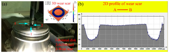
Figure 1.
Wear test instrument and 3D wear scar (a) and 2D profile of wear scar (b).
A field-emission scanning electron microscope (FESEM) (JEM-2100F, JEOL, Tokyo, Japan) was used to observe the morphology of the microstructure and wear scar. To determine the morphology of spherical carbides, samples were polished to 0.5 μm and then etched by 4% nitric acid alcohol. The diameter and volume fraction of spherical carbides was measured using Image-pro Plus software (Image-pro Plus 6.0, Media Cybernetics, Rockville, MD, USA). The oxygen content of the wear scar was tested by energy dispersive spectroscopy (EDS) (INCAx-sight, OXFORD, Oxford, UK). To obtain the volume fraction of retained austenite, X-ray diffraction (XRD) (D/max–2500, Rigaku, Tokyo, Japan) was employed with Cu–Ka radiation from 21° to 103° of ψ angles at a scanning speed of 0.01°/min. In addition, the microhardness was tested using a microhardness tester (HV-1000A, HUAYIN, China) with a load of 0.5 kg and a dwell time of 10 s.
3. Results
3.1. Volume Fraction of Spherical Carbides and Retained Austenite
The SEM images in Figure 2 present the morphology and distribution of spherical carbides, which are mainly affected by the degree of cold deformation and the austenitizing time. Figure 3 shows the corresponding spherical carbide size distribution in specimens with and without CRR with different austenitizing times. When austenitizited for 10 min, the Blank/10 specimen revealed a large number of spherical carbides in the martensite matrix (Figure 2a). The sizes of the spherical carbides in the Blank/10 specimen were between 0.4 and 0.7 μm. Meanwhile, the volume fraction of spherical carbides (VFSC) and average diameter of spherical carbides (ADSC) of the Blank/10 specimen were 7.26% and 0.528 μm, respectively (Figure 3a). Compared with the Blank/10 specimen, the CRR/10 specimen had a markedly smaller quantity of carbides, as shown in Figure 2b and Figure 3b.
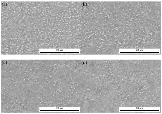
Figure 2.
Morphology of spherical carbides after quenching and tempering (QT) with and without cold ring rolling (CRR) under different austenitizing times: Blank/10 specimen (a), CRR/10 specimen (b), Blank/20 specimen (c), and CRR/20 specimen (d).
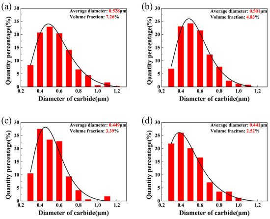
Figure 3.
Dimension distributions of spherical carbides after QT with and without CRR under different austenitizing times: Blank/10 specimen (a), CRR/10 specimen (b), Blank/20 specimen (c), and CRR/20 specimen (d).
Due to the continuous dissolution of carbides austenitized at 845 °C, the carbides became fewer and finer with an increase in austenitizing time. The specimens with and without CRR with the austenitizing time of 20 min had much lower VFSC and ADSC values than the specimens with the austenitizing time of 10 min. However, when the austenitizing time increased to 20 min, the VFSC and ADSC values of specimens with and without CRR were similar. The Blank/20 specimen had a VFSC of 3.39% and an ADSC of 0.449 μm (Figure 3c), while the CRR/20 specimen had a VFSC of 2.52% and an ADSC of 0.441 μm (Figure 3d).
Figure 4 presents the XRD patterns with and without CRR under the austenitizing times of 10 and 20 min, respectively. The volume fractions of retained austenite (VFRA) were calculated according to the XRD patterns. When the austenitizing time was 10 min, the Blank/10 specimen had the VFRA of 11.5%. Meanwhile, the CRR/10 specimen had a higher VFRA of 13.1%. When the austenitizing time increased to 20 min, the values of VFRA with and without CRR were both much higher than those of 10 min. However, the values of VFRA of the Blank/10 and CRR/10 specimens were basically the same at 14.2% and 14.3%, respectively. It is obvious that the value of VFRA has a negative correlation with VFSC. This can be explained by carbide dissolution behavior in the austenitizing process. Carbide dissolution results in the enrichment of the carbon element in the austenite, which thus increases the stability of austenite.
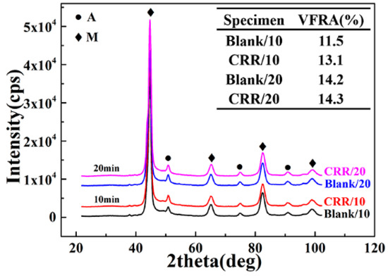
Figure 4.
X-ray diffraction (XRD) patterns of specimens after QT with and without CRR under different austenitizing times.
3.2. Wear Properties
Figure 5 shows the wear loss and friction coefficients during the wear test. The wear loss is presented in Figure 5a. The order of wear loss of the specimens was Blank/10 > CRR/10 > Blank/20 > CRR/20. The Blank/10 specimen had the largest wear loss, and the wear loss of the CRR/10 specimen was markedly lower. When the austenitizing time increased to 20 min, all the specimens had a much lower wear loss compared with the specimens with an austenitizing time of 10 min. The CRR/20 specimen had the lowest wear loss, but the improvement of wear resistance was only slight.
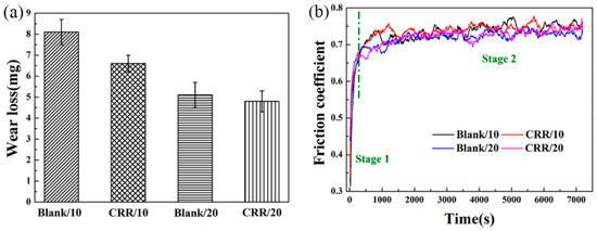
Figure 5.
Wear loss (a) and friction coefficient (b).
The corresponding friction coefficients during the wear process are displayed in Figure 5b. All friction coefficients had similar profiles. These can be divided into two stages and are in good agreement with the findings of Cao et al. [20]. The first stage is the break-in period, in which the friction coefficient increases rapidly. This can be due to the gradual formation of a larger contact area between the Si3N4 ball and the specimen. With further wear, the contact area remains stable and increases slowly. As a result, the friction coefficient becomes relatively stable and increases slowly during the second stage. Meanwhile, it can be seen that the friction coefficients of the specimens were similar under the same austenitizing times. However, the friction coefficients of specimens with the austenitizing time of 20 min were slightly lower than those of specimens with the austenitizing time of 10 min.
3.3. Typical Surface Morphology of the Wear Scar
Figure 6 shows the morphologies of the wear scars, and Figure 7 shows the corresponding surface roughness. When the austenitizing time was 10 min, the Blank/10 specimen had a typical worn morphology of adhesive wear, as shown in Figure 6a. Along the sliding direction, severe plastic deformation and ploughing accompanied by a large amount of fatigue flaking and wear debris detached from the matrix were observed. Severe plastic deformation and fatigue flaking resulted in a high surface roughness. The roughness of the Blank/10 specimen was the highest. Compared with the Blank/10 specimen, the CRR/10 specimen had a similar morphology but the degree of plastic deformation and wear debris was much less, as shown in Figure 5b. Moreover, the roughness parameters of the CRR/10 specimen (Sa = 0.932 μm, Sq = 1.580 μm and Sku = 7.726) in Figure 7b were lower than those of the Blank/10 specimen (Sa = 1.726 μm, Sq = 2.768 μm, and Sku = 16.306) in Figure 7a.
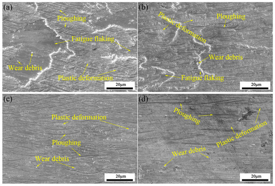
Figure 6.
Typical wear scar morphology of the Blank/10 specimen (a), CRR/10 specimen (b), Blank/20 specimen (c), and CRR/20 specimen (d).
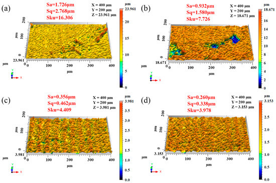
Figure 7.
Typical wear scar roughness of the Blank/10 specimen (a), CRR/10 specimen (b), Blank/20 specimen (c), and CRR/20 specimen (d).
When the austenitizing time increased to 20 min, the typical morphology of specimens was markedly different from that of 10 min. Only slight ploughing and plastic deformation were seen in the Blank/20 specimen (Figure 6c) while the fatigue flaking was insignificant. At the same time, much less ploughing and plastic deformation existed on the worn surface of the CRR/20 specimen, as shown in Figure 6d. The roughness parameters of the CRR/20 specimen (Sa = 0.260 μm, Sq = 0.338 μm and Sku = 3.978) in Figure 7d were still lower than those of the Blank/20 (Sa = 0.356 μm, Sq = 0.462 μm, and Sku = 4.409) specimen in Figure 7c.
3.4. Typical Cross Section Morphology of the Wear Scar
Figure 8 illustrates the cross section of the worn surface, which clearly consists of wear debris, lubricating film, and matrix. In Figure 8a, a large number of coarse carbides can be seen in the matrix of the Blank/10 specimen. Meanwhile, obvious cracks exist at the lubricating film-matrix and carbide–matrix interface. The CRR/10 specimen had similar morphology to the Blank/10 specimen (Figure 8b), but with fewer cracks. When the austenitizing time increased to 20 min, even fewer cracks and smaller carbides were seen in the matrix (Figure 8c,d). Moreover, little difference was found between the Blank/20 and CRR/20 specimens.
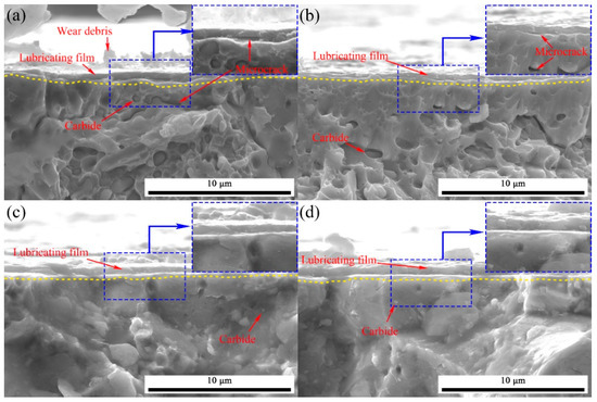
Figure 8.
Typical wear scar morphology of cross sections of the Blank/10 specimen (a), CRR/10 specimen (b), Blank/20 specimen (c), and CRR/20 specimen (d).
4. Discussion
4.1. Microstructure Evolution
In this work, severe deformation caused by CRR resulted in a large number of low angle boundaries in the ferrite of spheroidized GCr15 bearing steel [13]. Subsequently, the low angle boundary led to fine austenite grain, providing more diffusion channels. The dissolution behavior of carbides in high carbon steel during austenitizing is influenced by the diffusion of alloying elements and is closely related to the number of diffusion paths. In other words, pre-cold deformation by CRR increases the diffusion channels, which accelerates the dissolution of carbides during the early stage of the austenitizing process. Therefore, when austenitizing time is the same, specimens with CRR will present lower carbide content and compact carbide distribution after quenching and tempering, as shown in Figure 2a and Figure 3a.
On the other hand, the concentration gradient of carbon at the interface between carbide and austenite has an important influence on the dissolution rate of carbide. Zhao et al. provided an analytical model to show the relationship between the isothermal dissolution degree of carbides and the concentration gradient of carbon at the carbide/austenite interface [21]. In the early stage of austenizing, the concentration gradient changes rapidly. Then, in the late stage, the rate of change decreases significantly. Therefore, it is controlled by diffusion of the alloying elements. The dissolution behavior of carbides is also consistent with the changes in the interfacial element gradient, leading to a lower volume fraction and larger average size after quenching and short tempering.
In general, both exerting CRR and prolonged austenitizing time promotes the dissolution of carbides during austenitizing. The experimental results in this work show that when the austenitizing time is short, grain refinement plays a major role in promoting the dissolution of carbides, so the specimens with CRR have significantly fewer undissolved carbides. When the austenitizing time is prolonged, the concentration gradient of carbon at the carbide/austenite interfaces is still the fundamental reason for the degree of carbide dissolution during quenching. Therefore, the differences in spherical carbides in specimens with and without CRR become insignificant.
For high carbon steel, carbide dissolution during heat-treatment processes determines the phase content and microstructure after martensitic quenching, and the corresponding mechanical properties after tempering [22,23]. The acceleration of carbide dissolution increases the content of retained austenite. As a result, the trend in retained austenite content can be inferred according to the trend in spherical carbides with different CRR and austenitizing conditions.
4.2. Wear Mechanism
The effect of cold ring rolling (CRR) on the dry wear behaviors of GCr15 bearing steel was investigated, finding that CRR significantly decreases the wear loss under a short austenitizing time, while it contributes insignificantly to the wear resistance with a longer austenitizing time. These differences in wear resistance can be attributed to differences in crack initiation and propagation as well as the different plastic deformation behaviors.
Under a short austenitizing time, it was shown in Figure 8b that CRR reduces crack initiation and propagation, which can be attributed to the increased VFRA and decreased VFSC. During the wear test, tensile stress exists in the subsurface and especially at the carbide–matrix interface [18]. When the tensile stress exceeds the bond strength between carbides and the matrix, fatigue cracks will preferentially initiate at the carbide–matrix interface. It is known that retained austenite plays an important role in relieving the stress concentration and inhibiting the initiation of cracks due to its good capacity for plasticity [19]. For the CRR specimens with higher VFRA (Figure 4), cracks in the subsurface and the carbide–matersite interface thus decrease, as shown in Figure 8b. Meanwhile, the decreases in VFSC and ADSC in the CRR specimens could also decrease the initial cracks during the wear test [24]. As a result, fatigue flaking and wear debris decreases for the CRR specimens, thereby contributing to the decreased wear loss.
In addition, plastic deformation behavior could be another important mechanism for the increased wear resistance of the CRR/10 specimen. Due to plastic deformation behavior on the worn surface, a large number of bulges are generated and extruded to the lamellae (Figure 6a). Once the plastic deformation accumulates continuously, the lamellae will detach from the surface and form wear debris. Meanwhile, the hardness of the matrix determines the resistance of the pressed depth of the friction pair into the wear scar, with greater hardness indicating less plastic deformation. Accordingly, less plastic deformation will occur during wear testing for the CRR/10 specimen with a greater hardness (Figure 6b). Moreover, the VFRA in the CRR/20 specimen decreases from 14.3% to 7.7% after wear (Figure 9b), demonstrating that a substantial amount of retained austenite would be induced to transform the martensite under the alternating stress generated by a hard counterface ball. The transformation of γ to α therefore increases the hardness of the wear scar from 766to 836 HV, as shown in Figure 9a.
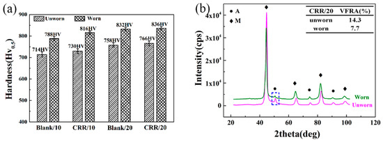
Figure 9.
Hardness of specimens (a) and XRD patterns of CRR/20 specimen (b) before and after wear.
The wear loss significantly decreases for the specimens with a long austenitizing time, while the enhancement of wear resistance induced by CRR becomes insignificant. This can be ascribed to the slight differences in microstructure and hardness between the Blank/20 and CRR/20 specimens.
The friction coefficient is closely related to plastic deformation and fatigue flaking. Under a short austenitizing time, severe plastic deformation and fatigue flaking can both be found in the specimens with and without CRR. Severe plastic deformation results in a large contact area between the friction pairs, and thus contributes to an increase in the friction coefficient. Moreover, as lubricating film can reduce the friction coefficient [25,26], the fatigue flaking will destroy the lubricating film and lead to a higher friction coefficient. With an increase in austenitizing time, the wear mechanism changes to slight ploughing and plastic deformation, while fatigue flaking is hard to find. Therefore, the friction coefficient of specimens with a long austenitizing time is lower than that of specimens with a short austenitizing time, as indicated in Figure 4.
5. Conclusions
This work focuses on the effect of CRR on wear resistance of GCr15 bearing steel after QT with different austenitizing times. The conclusions are as follows:
1. With a short austenitizing time of 10 min, CRR increases the retained austenite content, decreases the undissolved carbide content and improves hardness. The variations of microstructure and hardness reduce the ploughing and plastic deformation as well as fatigue flaking in the wear scar. As a result, the wear loss of a CRR specimen is decreased.
2. With a longer austenitizing time of 20 min, the effects of CRR on the retained austenite content, undissolved carbide content, and hardness are not significant. The difference in wear morphology between specimens with and without CRR is slight. Therefore, the wear loss is similar for specimens with and without CRR under an austenitizing time of 20 min.
3. However, with a short austenitizing time of 10 min, significantly increased retained austenite content, decreased undissolved carbide content, and greater hardness is observed in specimens both with and without CRR. The morphology changes from severe ploughing, plastic deformation, and fatigue flaking with an austenitizing time of 10 min to slight ploughing and plastic deformation with an austenitizing time of 20 min. As a result, the wear loss of specimens with an austenitizing time of 20 min is much lower than that of specimens with an austenitizing time of 10 min.
Author Contributions
Conceptualization, B.L., H.M. and X.L.; Validation, W.W. and H.M.; Formal Analysis, W.W. and B.L.; Writing—Review and Editing, B.L. and X.L.
Funding
This research was funded by the National Natural Science Foundation of China (Grant Nos. 51605355, 51875426), the Innovative Research Team Development Program of Ministry of Education of China (No. IRT_17R83) and the State Key Laboratory of Materials Processing and Die & Mould Technology, Huazhong University of Science and Technology (P2019-017).
Conflicts of Interest
The authors declare no conflict of interest.
References
- Burrier, H. ASM Handbook Properties and Selection: Iron Steels and High Performance Alloys; ASM International: Materials Park, OH, USA, 1987; Volume 1, pp. 380–388. [Google Scholar]
- Lu, X.; Qian, D.; Li, W.; Jin, X. Enhanced toughness of bearing steel by combining prior cold deformation with pre-quenching and bainite transformation. Mater. Lett. 2019, 234, 5–8. [Google Scholar] [CrossRef]
- Bhadeshia, H.K.D.H. Steel for bearings. Prog. Mater. Sci. 2012, 57, 268–435. [Google Scholar] [CrossRef]
- Hua, L.; Huang, X.G.; Zhu, C.D. Theory and Technology of Ring Rolling; China Mechanical Industry Press: Beijing, China, 2001. [Google Scholar]
- Qian, D.-S.; Hua, L.; Pan, L.-B. Research on gripping conditions in profile ring rolling of raceway groove. J. Mater. Process. Tech. 2009, 209, 2794–2802. [Google Scholar] [CrossRef]
- Hua, L.; Zhao, Z.Z. The extremum parameters in ring rolling. J. Mater. Process. Tech. 1997, 69, 273–276. [Google Scholar]
- Qian, D.S.; Hua, L. Blank design optimization for stepped-section profile ring rolling. Sci. Chin. Technol. Sci. 2010, 53, 1612–1619. [Google Scholar] [CrossRef]
- Qian, D.; Pan, Y. 3D coupled macro-microscopic finite element modelling and simulation for combined blank-forging and rolling process of alloy steel large ring. Comp. Mater. Sci. 2013, 70, 24–36. [Google Scholar] [CrossRef]
- Hua, L.; Deng, J.; Qian, D.; Lan, J.; Long, H. Modeling and application of ring stiffness condition for radial-axial ring rolling. Int. J. Mach. Tool. Manuf. 2016, 110, 69–79. [Google Scholar] [CrossRef]
- Guo, J.; Qian, D.; Deng, J. Grain refinement limit during hot radial ring rolling of as-cast GCr15 steel. J. Mater. Process. Tech. 2016, 231, 151–161. [Google Scholar] [CrossRef]
- Ryttberg, K.; Wedel, M.K.; Recina, V.; Dahlman, P.; Nyborg, L. The effect of cold ring rolling on the evolution of microstructure and texture in 100Cr6 steel. Mater. Sci. Eng. A 2010, 527, 2431–2436. [Google Scholar] [CrossRef]
- Lu, B.H.; Hua, L.; Han, X.H.; Zhou, G.H. Microstructure evolution of GCr15 in cold ring rolling and following heat treatment. Mater. Sci. Tech. 2016, 32, 1702–1711. [Google Scholar] [CrossRef]
- Li, Z.X.; Li, C.S.; Ren, J.Y.; Li, B.Z.; Zhang, J.; Ma, Y.Q. Effect of cold deformation on the microstructure and impact toughness during the austenitizing process of 1.0C–1.5Cr bearing steel. Mat. Sci. Eng. A 2016, 674, 262–269. [Google Scholar] [CrossRef]
- Beswick, J. Effect of prior cold work on the martensite transformation in SAE 52100. Metall. Trans. A 1984, 15, 299–306. [Google Scholar] [CrossRef]
- Perez, M.; Sidoroff, C.; Vincent, A.; Esnouf, C. Microstructural evolution of martensitic 100Cr6 bearing steel during tempering: From thermoelectric power measurements to the prediction of dimensional changes. Acta Mater. 2009, 57, 3170–3181. [Google Scholar] [CrossRef]
- Porter, D.A.; Easterling, K.E. Phase Transformation in Metals and Alloys, 2nd ed.; Chapman and Hall: London, UK, 1992. [Google Scholar]
- Olson, G.B. Introduction: Martensite in Perspective; Olson, G.B., Owen, W.S., Eds.; ASM International: Materials Park, OH, USA, 1992; p. 243. [Google Scholar]
- Wang, Y.; Lei, T.; Liu, J. Tribo-metallographic behavior of high carbon steels in dry sliding II. Microstructure and wear. Wear 1999, 231, 12–19. [Google Scholar] [CrossRef]
- Luo, H.; Liu, J.J.; Zhu, B.L. The behaviour of block-like residual austenite of 52100 steel in sliding wear. Wear 1994, 174, 57–61. [Google Scholar] [CrossRef]
- Cao, Y.J.; Sun, J.Q.; Ma, F.; Chen, Y.Y.; Cheng, X.Z.; Gao, X.; Xie, K. Effect of the microstructure and residual stress on tribological behavior of induction hardened GCr15 steel. Tribol. Int. 2017, 115, 108–115. [Google Scholar] [CrossRef]
- Zhao, L.; Vermolen, F.J.; Sietsma, J.; Wauthier, A. Cementite dissolution at 860 °C in an Fe-Cr-C steel. Metall. Trans. A 2006, 37, 1841–1850. [Google Scholar] [CrossRef]
- Chae, J.-Y.; Jang, J.-H.; Zhang, G.; Kim, K.-H.; Lee, J.-S.; Bhadeshia, H.K.D.H.; Suh, D.-W. Dilatometric analysis of cementite dissolution in hypereutectoid steels containing Cr. Scr. Mater. 2011, 65, 245–248. [Google Scholar] [CrossRef]
- Barrow, A.T.W.; Kang, J.-H.; Rivera-Díaz-Del-Castillo, P.E.J. The ϵ → η → θ transition in 100Cr6 and its effect on mechanical properties. Acta Mater. 2012, 60, 2805–2815. [Google Scholar] [CrossRef]
- Wang, F.; Qian, D.; Hua, L.; Lu, X. The effect of prior cold rolling on the carbide dissolution, precipitation and dry wear behaviors of M50 bearing steel. Tribol. Int. 2019, 132, 253–264. [Google Scholar] [CrossRef]
- Takagi, R. Effect of oxide film of 52100 steel on the friction in vacuum. ASLE Trans. 1970, 13, 87–98. [Google Scholar] [CrossRef]
- Zhu, X.; Wei, X.; Huang, Y.; Wang, F.; Yan, P. High-temperature friction and wear properties of NiCr/hBN self-lubricating composites. Metals 2019, 9, 356. [Google Scholar] [CrossRef]


© 2019 by the authors. Licensee MDPI, Basel, Switzerland. This article is an open access article distributed under the terms and conditions of the Creative Commons Attribution (CC BY) license (http://creativecommons.org/licenses/by/4.0/).