Article

Study on Sulfur Transfer Behavior during Refining of Rejected Electrolytic Manganese Metal

1
The State Key Laboratory of Refractories and Metallurgy, Wuhan University of Science and Technology, Wuhan 430081, China
2
Key Laboratory for Ferrous Metallurgy and Resources Utilization of Ministry of Education, Wuhan University of Science and Technology, Wuhan 430081, China
3
School of Metallurgy, Northeastern University, Shenyang 110004, China
*
Author to whom correspondence should be addressed.
Metals 2019, 9(7), 751; https://doi.org/10.3390/met9070751
Submission received: 3 June 2019 / Revised: 1 July 2019 / Accepted: 3 July 2019 / Published: 4 July 2019

Abstract

:
A slag treatment method was proposed to recycle rejected electrolytic manganese metal. To improve the sulfur removal ratio, computational fluid dynamics and experimental studies of the sulfur transfer behavior during the refining process were carried out. Experiments of slag-metal reaction for desulfurization were carried out using an electric resistance furnace at temperatures ranging from 1773 K to 1923 K. A transient three-dimensional coupled numerical model was established to represent the three-phase flow, heat and mass transfer in the experiment. The desulfurization rate was described by a metallurgical kinetics module, which was related to the slag composition, the interfacial tension coefficient, the flow and the temperature of the melt. The predicted sulfur content agreed reasonably well with the measured data. The temperature of the fluids at the outer side of the crucible was higher than that at the center, resulting in a larger sulfur partition ratio and a more vigorous flow. The sulfur transfer rate was higher at the outer edge of the molten slag–molten manganese interface. The sulfur removal ratio increased from 51.4% to 85.1% with a change in heating temperature from 1773 K to 1873 K, and slightly dropped to 83.3% when the heating temperature increased to 1923 K. The heating temperature of 1873 K is the optimal choice for recycling in the present work.

Graphical Abstract

1. Introduction

Manganese metal is critical to the development of industry. About 90% of manganese metal is consumed by the iron and steel industry, since manganese can efficiently remove oxygen and sulfur, and increase the hardenability and the tensile strength of steel alloy. Important non-metallurgical applications of manganese metal include battery cathodes, soft ferrites used in electronics and water treatment chemicals, etc. [1,2]. Nowadays, most electrolytic manganese metal (EMM) is produced by hydrometallurgical technology, which was proposed by the U.S. Bureau of Mines in 1968. To increase the current efficiency and change the crystal size and structure of the deposit, sulfur dioxide is added into the electrolyte during the electrolytic process. The use of the sulfur dioxide, however, causes a significant increase in the sulfur content of the produced EMM, and thus increases the rejection rate of the EMM [3,4]. Due to the excessive sulfur content, the rejected EMM, as shown in Figure 1, cannot be sold to end-users, resulting in an enormous waste of resources.
The mechanical performances of steel products, such as strength, ductility and toughness, are dramatically reduced by excess sulfur. The importance of sulfur removal has thus been highlighted for several decades in the steelmaking process [5]. The slag treatment method is used extensively to diminish the sulfur content in the molten steel due to its high efficiency and operation convenience [6,7,8,9]. Through optimizing the slag composition and the heating temperature, a higher desulfurization rate is expected to be achieved. Furthermore, the slag treatment method can be easily applied to continuous production, so as to increase productivity. After the refining process, the desulfurization slag can then be utilized in other industrial applications such as land filling, road project and cement production. As a result, no extra waste would be created in the recycling of the rejected metal by using the slag treatment method. At high temperature, a layer of molten slag, floating on the molten steel, is formed, and sulfur is eliminated from the molten steel to the molten slag by the following reaction [10]:
(CaO) + [S] = (CaS) + [O]
where [ ] and ( ) imply the matter dissolved in the molten steel and the molten slag, respectively.
To recycle the rejected EMM, the slag treatment method is adopted in the present work to remove sulfur. Given the property discrepancy between the molten steel and the molten manganese, it is crucial to figure out the sulfur transfer behavior during the slag treatment for achieving a higher efficiency. Conducting experiments on a real apparatus is the most intuitive approach for studying the recycling of the rejected EMM. However, in the majority of cases, the limitations of the measuring devices and the hostile process environment result in the information provided by the experiments being insufficient. The flow pattern and temperature distribution are unknown to us. According to the studies of the molten steel desulfurization, the composition of the slag, heating temperature and melt flow seriously affect the sulfur removal [11,12,13]. With the constant increasing of the computation resource and numerical technique, the computational fluid dynamics (CFD) approach, which is able to provide comprehensive data, becomes a powerful tool in understanding the characteristics of the complex recycling process. An original CFD and thermodynamic coupled model was established by Jonsson et al. for illustrating the sulfur removal from the molten steel to the molten slag in a gas-stirred ladle [14]. A metallurgical thermodynamic module was developed to define the desulfurization rate. The thermodynamic variables such as oxygen activity and sulfide capacity, influenced by the flow characteristics, were offered by the CFD module. An improved CFD-simultaneous reaction model for the desulfurization in the gas-stirred ladle was recently created by Lou and Zhu [13]. The Euler-Euler approach was used to consider the bubbly plume flow. The effects of the oxygen absorption and oxidation reaction at the molten slag eyes on sulfur partition ratio were included. The heat transfer, however, was ignored in the above two numerical models.
To achieve a higher recycle efficiency, the present work aims to fully understand the sulfur transfer behavior during the slag treatment of the rejected EMM. Slag-metal reaction experiments were first carried out by using an electric resistance furnace filled with argon gas. After the slag treatment, the sulfur contents in the manganese metal and the slag were measured by carbon-sulfur analyzer and inductively coupled plasma mass spectrometry, respectively. A transient three-dimensional comprehensive mathematical model was then established to represent the three-phase flow, heat and mass transfer in the experiment. The desulfurization rate was described by developing a metallurgical kinetics module, which was related to the slag composition, the interfacial tension coefficient, the flow and the temperature of the melt. To examine the model accuracy, a thorough comparison between the experimental and the numerical results was conducted.

2. Experiment

Figure 2 shows the schematic diagram of the experimental set-up. A vertical electrical resistance furnace using MoSi2 heating elements was employed for melting of the slag and the rejected EMM in an argon atmosphere. An Al2O3 working tube with 90 mm inner diameter and 800 mm length was closed in the furnace by water-cooled caps at two ends. Moreover, a gas outlet and a sampling hole were found at the upper lid, and a gas inlet and a hole for the thermocouple were at the lower one.
The initial compositions of the rejected EMM and the slag are listed in Table 1 and Table 2. To prepare the slag sample, reagent-grade CaF2 and Al2O3 powders were first heated in a muffle furnace (Wuhan Dianlu Factory, Wuhan, China) for around 10 h at 673 K to remove moisture. The two powders were then well mixed and melted in a graphite crucible using an induction furnace (Wuhan Dianlu Factory, Wuhan, China) filled with high-purity (99.999%) argon gas. The melt process was kept in the furnace for 10 min at 1773 K. The quenched slag was thoroughly ground and then decarburized by heating in a muffle furnace (Wuhan Dianlu Factory, Wuhan, China) for about 10 h at 1273 K. The carbon content in the decarburized slag was confirmed to be lower than 0.001 mass%.
A BN crucible, which contained 180 g scrap of the rejected EMM, was first placed in the center of the Al2O3 tube in the furnace [15]. By flowing the high-purity (99.999%) argon gas at a rate of 5 NL/min, the furnace was heated to a specified temperature, ranging from 1773 K to 1923 K, at a heating rate of 10 K/min. After the desired temperature was reached and the melting of the rejected EMM was completed, the argon gas was temporarily shut off, and then 60 g slag was rapidly added into the BN crucible by using a quartz tube through the sampling hole. The argon gas was turned on afterwards, and the flow rate was set as 2 NL/min. After a certain reaction time, varying from 5 min to 20 min, the BN crucible was withdrawn from the furnace and quickly quenched in water. The samples of the reacted slag and refined manganese metal, as shown in Figure 3, were collected from the crucible, and the sulfur contents in the slag and the metal samples were measured by inductively coupled plasma mass spectrometry (Tailun, Shanghai, China) and carbon-sulfur analyzer (Jinbo, Wuxi, China), respectively [16,17].

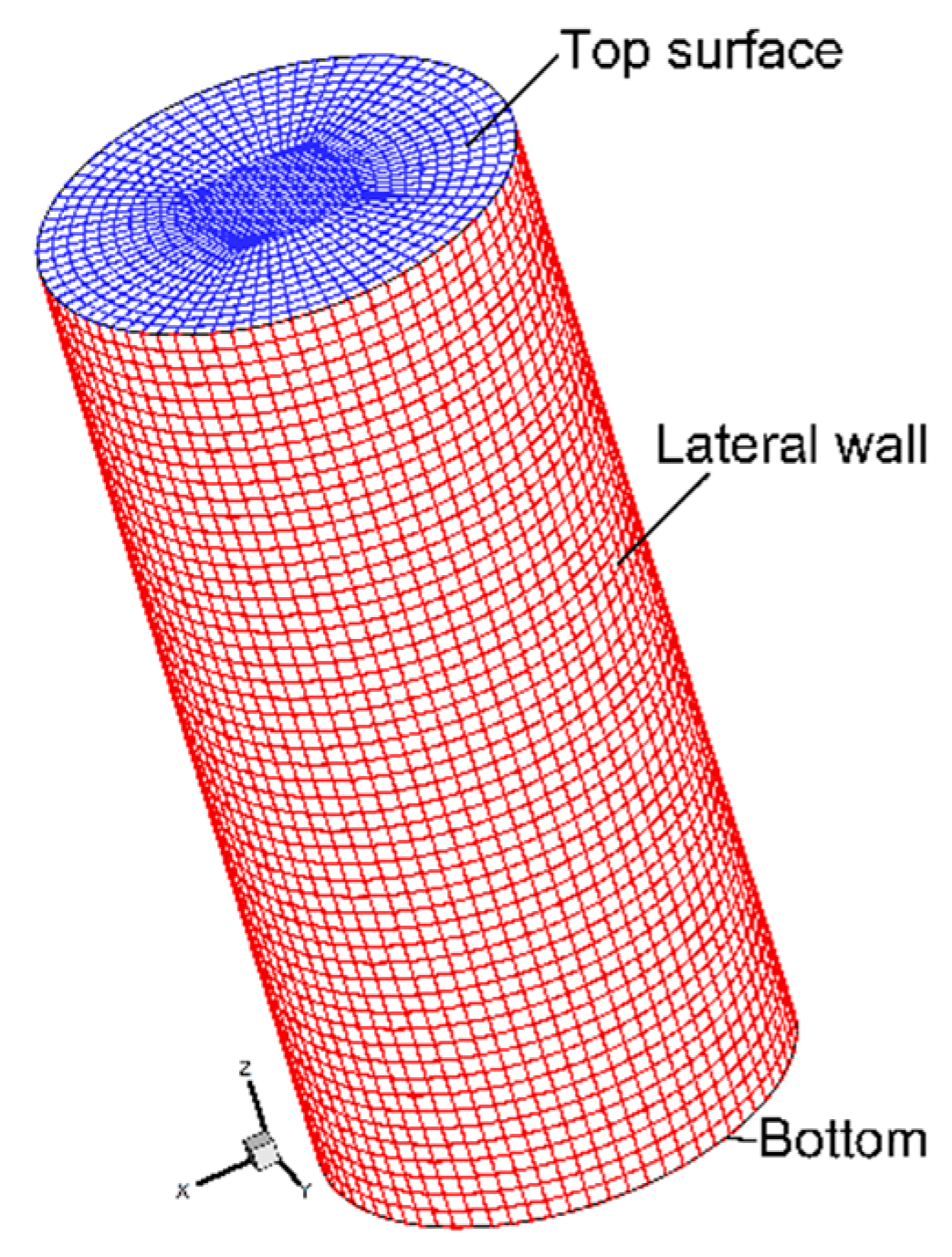
3. CFD Modeling Framework

In this model, the argon gas, the molten slag and the molten manganese were taken into account in the computational domain, while the BN crucible was ignored. The three fluids were treated as incompressible Newtonian fluids. Given that the temperature of the slag treatment was quite high, the influences of the temperature on the densities and the viscosities of the three fluids were included [18,19,20]. In addition, the coefficient of the interfacial tension was assumed to be a function of the temperature and the sulfur concentration, since the sulfur is a surface active element [21,22]. Other properties of the three fluids were considered to be constant. The present work focused on the sulfur transfer behavior during the slag treatment of the rejected EMM. The migration of other elements was therefore disregarded.
The volume of fluid (VOF) approach, proposed by Hirt and Nichols [23], was adopted to track the movement of the interfaces between the argon gas and the molten slag, and the molten slag and the molten manganese. The continuity equation for the volume fraction of the three fluids was expressed as:
( α i ρ i ) t + ( α i ρ i v ) = 0   with   i   =   g ,   s   or   m
α g + α s + α m = 1
where g, s and m denoted the argon gas, molten slag and molten manganese, respectively, and α i indicated the volume fraction, which was updated at each time step to represent the redistribution of the three fluids over time. ρ i was the density, and t was the time. Additionally, v was the velocity field shared by the three fluids due to the use of the VOF method, and was determined by a single set of momentum equation established throughout the computational domain [24]:
( ρ v ) t + ( ρ v v ) = p + [ μ ( v + v T ) ] + F s t + F s + F t
where ρ was the density and μ was the viscosity, which were determined by the volume fraction and the corresponding property of each fluid:
ρ = α i ρ i   and   μ = α i μ i
The last two terms, F s and F t , represented the solutal and the thermal buoyancy forces solved by the Boussinesq approximation. Additionally, F s t indicated the interfacial tension described by the continuum surface force model [25]. As mentioned above, the surface active element sulfur can affect the coefficient of the interfacial tension. In the present research, a modified form of Butler’s equation was employed to predicate the coefficient of the interfacial tension between the molten manganese and the argon gas σ m g [26]:
σ m g = σ m 0 + R T S m ln ( a m s a m b ) = σ m 0 + R T S m ln ( γ m s γ m b ) + R T S m ln ( x m s x m b )
where σ m 0 was the coefficient of the interfacial tension of the pure manganese [21], R was the gas constant, and T was the temperature. S m was the molar surface area of manganese, and was calculated from the molar volume of V m based on the hypothesis that the manganese atoms occupy a closely packed structure in a monolayer:
S m = 1.091 N A 1 / 3 V A 2 / 3
where N A was the Avogadro’s number. Moreover, a m s and a m b were the activity of manganese at the interface and in the bulk of the molten manganese, respectively, and can be determined by the activity coefficient and molar fraction of manganese:
a m s = x m s γ m s   and   a m b = x m b γ m b
The coefficient of the interfacial tension between the molten slag and the argon gas, σ s g , can also be derived using the modified Butler’s equation [27]:
σ s g = σ C a F 2 0 + R T S C a F 2 ln ( M C a F 2 s M C a F 2 b )
where σ C a F 2 0 was the coefficient of the interfacial tension of the pure CaF2 [28]. M C a F 2 s and M C a F 2 b were the ionic radius fractions of the CaF2 at the interface and in the bulk of the liquid, respectively, and can be evaluated by the ionic radius and the molar fraction:
M C a F 2 s M C a F 2 b = ( R C a 2 + / R F ) ( x C a F 2 s / x C a F 2 b ) ( R C a 2 + / R F ) ( x C a F 2 s / x C a F 2 b ) + ( R A l 3 + / R O 2 ) ( x A l 2 O 3 s / x A l 2 O 3 b )
where R C a 2 + , R F , R A l 3 + and R O 2 indicated the radius of the corresponding ion. x C a F 2 s , x C a F 2 b , x A l 2 O 3 s and x A l 2 O 3 b represented the molar fraction of the CaF2 and the Al2O3 at the interface and in the bulk of the liquid, respectively.
After obtaining the coefficients of the interfacial tension between the molten manganese and the argon gas, and the molten slag and the argon gas, the coefficient of the interfacial tension between the molten manganese and the molten slag thus can be calculated [29]:
σ m s = σ m g + σ s g 2 ϕ ( σ m g σ s g ) 0.5
ϕ = Δ G m s a ( Δ G m g c Δ G s g c ) 0.5
where Δ G m s a was the free energy of adhesion between the molten manganese and the molten slag. Δ G m g c and Δ G s g c were the geometric means of the free energy of cohesion of the separate molten manganese and the molten slag, respectively. It should be noted that ϕ was a semi-empirical correction factor, and it varied from 0.5 to 0.6 for the CaO-CaF2-Al2O3 molten slag according to the research of Cramb and Jimbo [30]. A value of 0.55 was adopted in the present work.
The flow of the argon gas in the crucible was observed in a strong turbulence because of the high temperature, while the motion of the molten slag and the molten manganese in the crucible was somewhere weakly turbulent according to the observations in the experiment. The RNG k-ε turbulence model was employed to provide the turbulent viscosity, since it is capable of recognizing the behavior of flows with a wider range of Reynolds number [31]. Additionally, an enhanced wall function was invoked to cooperate with the RNG k-ε turbulence model for a better description of the near-wall region.
The energy equation, shared among the three fluids, was [32]:
( ρ h ) t + ( v ρ h ) = ( k e f f T )
where keff was the effective thermal conductivity, and h was the sensible enthalpy of the mixture phase, which was determined by the volume fraction, the density and the specific heat of each fluid, and the shared temperature:
h = α g ρ g h g + α s ρ s h s + α m ρ m h m α g ρ g + α s ρ s + α m ρ m
h g = T r e f T c p , g d T ,   h s = T r e f T c p , s d T   and   h m = T r e f T c p , m d T
where ρ g , ρ s and ρ m was the density of the argon gas, molten slag and the molten manganese, h g , h s and h m was the sensible enthalpy of the argon gas, molten slag and the molten manganese, respectively, and c p , g , c p , s and c p , m was the specific heat at constant pressure of the argon gas, molten slag and the molten manganese, respectively.
Due to the desulfurization reaction at the molten slag–molten manganese interface, sulfur in the molten manganese was continuously transferred to the molten slag. Meanwhile, the convection and diffusion of sulfur in the molten slag and the molten manganese also affected the reaction. In order to illustrate these phenomena, two convection-diffusion equations were established in the molten slag and the molten manganese:
( ρ c ) t + ( ρ v c ) = ( ρ D s c ) + S r
( ρ c ) t + ( ρ v c ) = ( ρ D m c ) S r
where c indicated the mass fraction of the sulfur. D s and D m represented the diffusion coefficient of the sulfur in the molten slag and the molten manganese, respectively. The source term, S r , indicated the reaction rate at the molten slag–molten manganese interface. To fulfill the mass conservation of sulfur, the source terms in the two equations were numerically equal but opposite in sign.
A kinetics module was developed, based on the two-film theory, to estimate the transfer rate of sulfur between the molten slag and the molten manganese [13,14]:
S r = k s k m ρ s L s k m ρ m + k s ρ s L s A ( w [ S ] w ( S ) L s )
where A indicated the interfacial area for the desulfurization reaction. k s and k m were the mass transfer coefficient of sulfur in the molten slag and the molten manganese, respectively, and were connected with the diffusion coefficient of sulfur, the turbulent dissipation rate and the viscosity:
k s = c D s 0.5 ( ε μ ) 0.25   and   k m = c D m 0.5 ( ε μ ) 0.25
where c was a constant which was equal to 0.4 in the present work [13], and ε was the turbulent dissipation rate. Additionally, L S was the sulfur partition ratio, which denotes the measure of the ratio of the mass fraction of sulfur in the molten slag to that in the molten manganese at the molten slag–molten manganese interface. This indicated the desulfurization ability of the molten slag and was defined as:
lg L S = 935 T + 1.375 + lg C S + lg f S lg a O
where f S and a O were the activity coefficient of sulfur and the activity of oxygen in the bulk of the molten manganese, respectively. C S was the sulfide capacity of the molten slag, which was introduced by Fincham and Richardson [33] for quantitatively evaluating the sulfur dissolution capacity of a molten slag, and was calculated using Young’s model [34].
The activity coefficient of sulfur depended upon the composition of the molten manganese based on the dilute solution theory [35]:
lg f i = e j i w [ j ]
where i and j denoted the dissolved elements in the molten manganese. All elements should be included except the solvent, i.e., molten manganese. w [ j ] was the mass fraction of element j in the molten manganese, and e i j was the interaction coefficient of the element j in terms of the element i.
The activity of oxygen in the molten manganese was assumed to be dominated by the activity of aluminum in the reaction [14]:
2[Al] + 3[O] = (Al2O3)
where [ ] and ( ) indicated that the substance was dissolved in the molten manganese and the molten slag, respectively. The equilibrium constant for this reaction could be expressed:
lg K = lg a A l 2 O 3 a A l 2 a O 3 = 45300 T 11.62
where a A l 2 O 3 was the activity of alumina in the molten slag, which was found to basically remain unchanged during the refining process [36]. a A l was the activity of aluminum in the molten manganese, and can be estimated by the activity coefficient and the mass fraction of aluminum in the molten manganese:
a A l = f A l w [ A l ]
Here, it should be noted that the estimation of the oxygen activity in molten manganese is questionable, since the aluminum metal was not used to deoxidize the molten slag in the desulfurization process. It is difficult to find an accurate mathematical description of the evolution of the oxygen activity in molten manganese. The aluminum activity was thus temporarily used to calculate the oxygen activity in the present work. Our next step will be to collect refined manganese metal samples during the desulfurization process, and measure the oxygen content in the samples. According to the measured data, we will try to establish a truthful mathematical description of the evolution of the oxygen activity in molten manganese, which can be coupled with the numerical model.
The alumina in the molten slag would be decomposed in the practical electroslag remelting process:
(Al2O3) → [Al] + [O]
Because the activity of alumina in the molten slag is relatively high, and temperature of the practical electroslag remelting process is around 2000–2200 K. Some aluminum would therefore enter into the molten manganese, and the order of magnitude of the aluminum mass fraction ranges from 10−5 to 10−4. In the present model, the mass fraction of aluminum, [Al], is supposed to be 0.005%.

4. Boundary Conditions

Figure 4 displays the boundaries of the computational domain and the mesh used in the simulation. As mentioned above, the BN crucible was put in the electric resistance furnace filled with argon gas in the experiment. The means of heat transfer between the BN crucible and the heating unit were therefore assumed to be convection and radiation. An emissivity and a heat convection coefficient were applied to the lateral wall. Additionally, the BN crucible was put on a refractory brick as shown in Figure 2. Due to the obstruction of the refractory brick, the radiation at the bottom of the BN crucible was negligibly small. An equivalent heat convection coefficient was therefore imposed at the bottom. The emissivity and the heat convection coefficient used in the present simulation were deduced from the experiment. In addition, a no-slip condition was employed to treat the flow near the lateral wall and the bottom, where the fluids were in contact with the BN crucible. As for the top surface of the BN crucible, one atmosphere pressure and a constant temperature were invoked for a better describe of the argon gas flow.

5. Numerical Procedure

The computational domain was discretized with a structured mesh, as shown in Figure 4. Here, the grid pattern is coarsely displayed for ease of visualization. Grid independence was checked using different sizes, with a total of 1,425,536, 871,249 and 531,360 control volumes. According to the calculated results, the relative deviation of the sulfur concentration between the first and second mesh systems was around 4.1%, and it was approximately 8.7% between the second and third mesh systems. Furthermore, the value of y+ of the second mesh was around 0.42. Considering the computational accuracy and efficiency, the mesh with 871,249 control volumes was reserved for the further simulation.
In the present work, the widely used commercial software ANSYS FLUENT 14.5 (ANSYS Inc., Canonsburg, PA, USA), based on the finite volume method, was employed to solve the governing equations. The development of the metallurgical kinetics module was accomplished by homemade codes. PRESTO and second-order upwind were adopted to discretize the pressure, momentum, energy and mass transfer equations. The SIMPLE algorithm was adopted for pressure-velocity coupling. Additionally, the interfaces between the three fluids were determined using the Geometric Reconstruction scheme. Default values of the factors under relaxation were used. The value of the residual was 10−8 for the convergence criteria of the energy equation, while was 10−6 for all other quantities. All the simulation scenarios were conducted with a time step of 10−4 s, and a complete scenario needed approximately 420 CPU hours with 8 compute cores of 4.2 GHz.

6. Results and Discussion

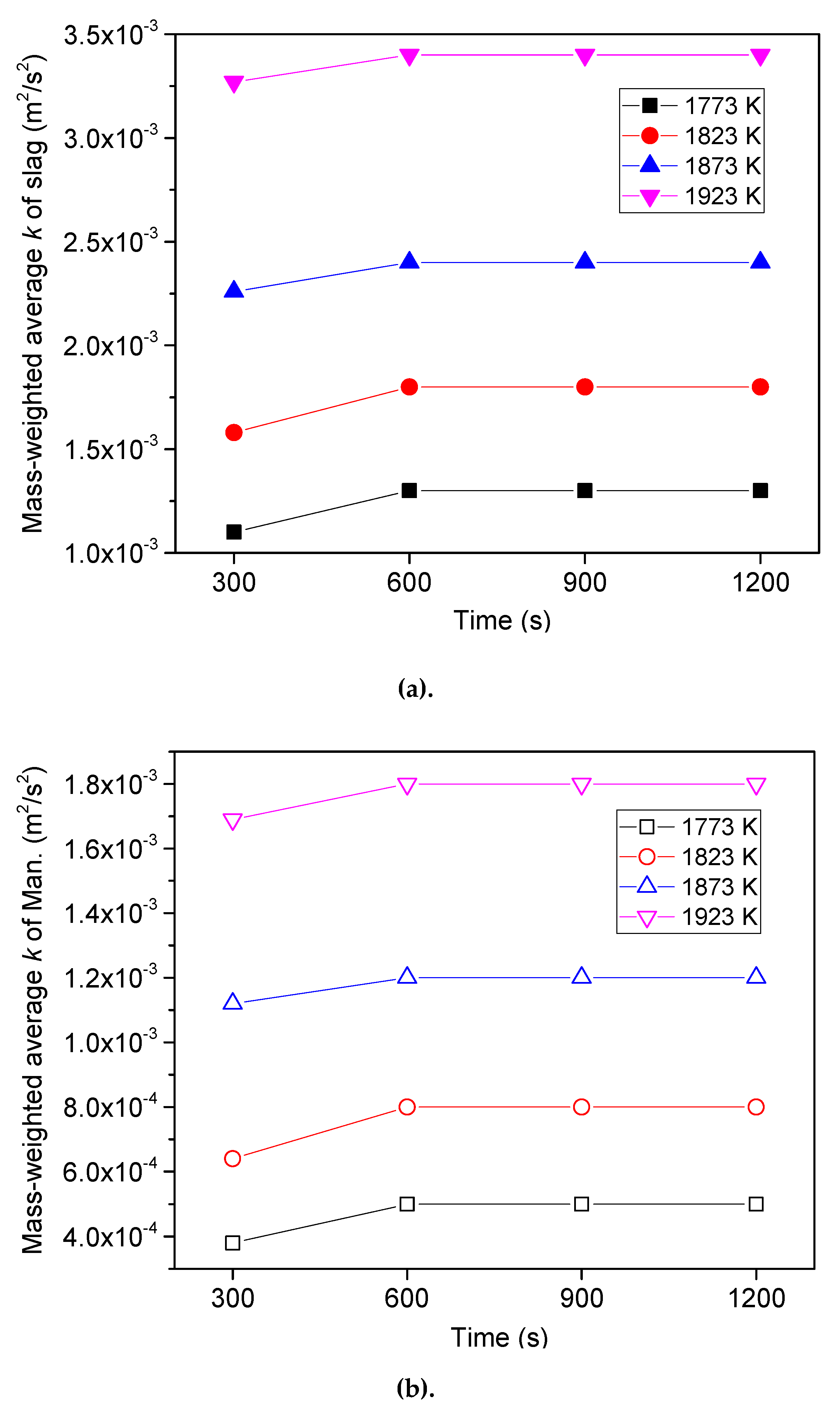
6.1. Flow Pattern and Temperature Distribution

Figure 5 shows the distribution of the three fluids at 600 s with the 1873 K heating temperature. The heavier molten manganese lies at the bottom of the crucible, and on top of it is a layer of molten slag. The upper part of the crucible is filled with argon gas. Due to the redox reaction, sulfur is transferred from the molten manganese to the molten slag through the molten slag–molten manganese interface. To record the change of variables such as temperature and sulfur concentration, two monitoring points were selected in the molten slag and the molten manganese.
Figure 6 represents the temperature distribution at 600 s at a heating temperature of 1873 K. It is clear that the temperature of the fluids at the outer side of the crucible is higher than that at the center, because the heating units are distributed around the crucible. The highest temperature, around 1743 K, is found at the outer edge of the slag, and moreover, the molten slag is hotter than the molten manganese, because of having a lower thermal conductivity. As stated above, the argon gas was blown into the reaction tube from the bottom of the furnace, resulting in a larger convection heat transfer coefficient. More heat is removed by the argon gas, and thus a lower temperature is observed at the base of the crucible.
Figure 7 displays the corresponding flow pattern of the fluids. The colder denser argon gas enters into the crucible from the center of the top surface and then flows out from the periphery of the top surface. Due to a higher temperature, the molten slag at the outer side of the crucible moves upward to the top layer and, from there, migrates to the center of the crucible along the argon gas–molten slag interface. In the meantime, the top molten slag would be cooled by the turbulent argon gas, causing the molten slag to sink. The downward streams then reverse when they reach the molten slag–molten manganese interface, creating a counter-clockwise circulation as observed in the right of Figure 7. Similarly, a pair of vortices can be found in the molten manganese. In addition, many small eddies appear near the molten slag–molten manganese interface, which significantly promotes the fluctuation of the interface. The interfacial area for the desulfurization reaction therefore increases.

6.2. Variation of Sulfur Concentration

Figure 8a,b indicates the distribution of the sulfur concentration in the molten slag and the molten manganese, respectively, at 600 s with a heating temperature of 1873 K. It is obvious that the sulfur content at the outer side of the bottom slag is much higher than that at the middle of the bottom slag. As mentioned above, the temperature at the outer layer of the crucible is higher. A larger sulfur partition ratio is therefore created according to Equation (20). Furthermore, the higher temperature is able to promote the movement of the molten slag and the molten manganese. As a consequence, a higher transfer rate of sulfur is generated at the outer edge of the molten slag–molten manganese interface, and accordingly, the sulfur concentration at the outer side of the upper part of the molten manganese is lower than that at the middle as shown in Figure 8b. Due to the vortex, more sulfur migrates along with the molten manganese to the corner of the bottom, where a higher concentration is observed.
Figure 9 shows the variation of the sulfur mass fraction at the point 2 in the molten manganese (as illustrated in Figure 5) over time with the four heating temperatures. All four sulfur contents decrease over time and become stable during the final stage of the refining process. However, the desulfurization rate and the final sulfur content are greatly influenced by the heating temperature. It is apparent that the sulfur content descends faster with the increasing heating temperature. The final sulfur content however varies in a non-monotonic way with the heating temperature. It decreases from 0.0486% to 0.0149% when the heating temperature increases from 1773 K to 1873 K, while slightly increasing to 0.0167% when the heating temperature continuously rises to 1923 K. The desulfurization rate with the 1923 K heating temperature is larger than that with the 1873 K heating temperature at the early stage, and the sulfur content of the former scenario is lower as well. Nevertheless, the desulfurization rate with the 1923 K heating temperature gradually decreases during the latter period, and the sulfur content with the 1923 K heating temperature begins to get higher than that with the 1873 K heating temperature after 900 s.
Figure 10 represents the variation of the sulfur mass fraction at point 1 in the molten slag (as illustrated in Figure 5) over time with the four heating temperatures. The four sulfur contents increase over time, and also tend to be stable during the final stage. More sulfur would enter into the molten slag with a higher heating temperature, as expected. The final sulfur content increases from 0.155% to 0.259% with heating temperature ranging from 1773 K to 1873 K, and slightly drops to 0.253% when the heating temperature changes to 1923 K.
The comparison of the sulfur mass fraction between the simulation and the experiment is also demonstrated in Figure 9 and Figure 10. A small discrepancy in the sulfur mass fraction between the prediction and the measurement can be observed, because some of the molten manganese would react with sulfur to form manganese sulfide inclusions, and part of these inclusions would residue in the molten manganese as presented in Figure 11. The generation of the manganese sulfide inclusion is ignored in the present numerical model. The relative error, however, is within the acceptable range.
Additionally, the measured sulfur mass fraction in the molten manganese at 1200 s with the 1923 K heating temperature is a little larger than that with the 1873 K heating temperature as seen in Figure 9, and in Figure 10, the measured sulfur mass fraction in the molten slag at 1200 s with the 1923 K heating temperature is less than that with a heating temperature of 1873 K. The variation tendency of the final sulfur mass fraction is the same as the predicted results. The reasonable agreement between the experimental and the simulated results therefore confirms the precision of the developed model.

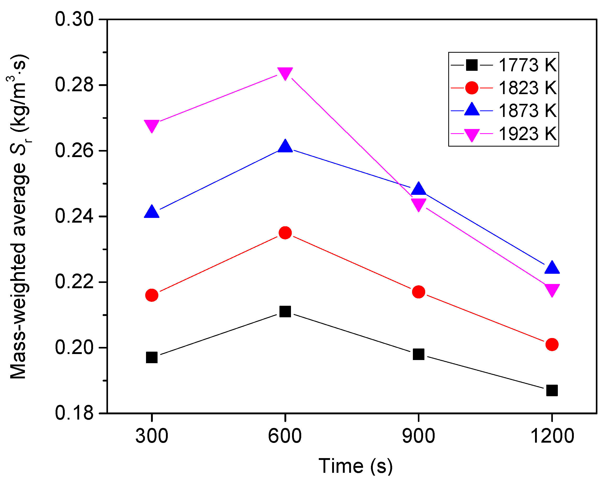
6.3. Effect of Heating Temperature

To figure out how the heating temperature affects the desulfurization, the changing of turbulence kinetic energy and interfacial tension coefficient were clarified. Figure 12 shows the calculated volume average temperature of the molten slag and the molten manganese. The temperature of the melt steadily increases and becomes stable after 600 s. With increasing heating temperature, the final temperature of the molten slag and the molten manganese increases from 1615 K to 1772 K and from 1605 K to 1769 K, respectively. Furthermore, the temperature difference between the molten slag and the molten manganese gradually decreases.
A higher temperature significantly promotes the action of the melt, as indicated in Figure 13. The turbulence kinetic energies of the molten slag and the molten manganese also become steady after 600 s. The final turbulence kinetic energy of the molten slag and the molten manganese ascends from 1.3 × 10⁻³ m2/s2 to 3.4 × 10⁻³ m2/s2 and from 5.1 × 10⁻⁴ m2/s2 to 1.8 × 10⁻³ m2/s2 when the heating temperature ranges from 1773 K to 1923 K. The growth rate of the turbulence kinetic energy also becomes larger with increasing heating temperature. The turbulence kinetic energy of the molten slag increases by 38.5% when the heating temperature changes from 1773 K to 1823 K, while it increases by 41.7% when the heating temperature is changed from 1873 K to 1923 K. Due to having a larger viscosity, the diffusion of sulfur in the molten slag is supposed to be the rate-limiting step for the desulfurization. In this regard, the desulfurization of the rejected EMM could be promoted if the temperature of the molten slag were elevated.
Figure 14 represents the effect of the heating temperature on the coefficient of the interfacial tension between the molten slag and the molten manganese. It is evident that a higher heating temperature can decrease the coefficient of the interfacial tension, resulting in a larger interfacial area for the desulfurization, as shown in Figure 15. The coefficient of the interfacial tension decreases by 13.1% and the interfacial area increases by 12.2% at 300 s when the heating temperature changes from 1773 K to 1923 K. On the other hand, the coefficient of the interfacial tension of each heating temperature decreases before 600 s, because the melt gradually gets hotter. However, the variation of the coefficient of the interfacial tension tells a different story after 600 s. The coefficient of the interfacial tension increases instead of decreasing. This can be attributed to the transfer of sulfur from the molten manganese to the molten slag. It is well known that sulfur, as a surface active element, can decrease the interfacial tension between the molten manganese and the argon gas. The interfacial tension between the molten manganese and the argon gas therefore tends to increase with the desulfurization. According to Equation (11), the interfacial tension between the molten slag and the molten manganese would become larger with the increasing interfacial tension between the molten slag and the argon gas if the interfacial tension between the molten slag and the argon gas exceeds a certain threshold. A higher coefficient of the interfacial tension would reduce the interfacial area. The interfacial area between the molten slag and the molten manganese with the 1773 K heating temperature is about 1287 mm2 at 600 s and drops to around 1143 mm2 at 900 s.
With the rising heating temperature, more sulfur would be transferred from the molten manganese to the molten slag before 900 s as demonstrated in Figure 9 and Figure 10. In addition, because of this, the increase of the coefficient of the interfacial tension is accelerated. It is clear that the increase of the coefficient of the interfacial tension with the 1873 K heating temperature begins to lag behind that with the 1923 K heating temperature after 600 s, as illustrated in Figure 14. The coefficient of the interfacial tension with the 1923 K heating temperature is a little higher than that with the 1873 K heating temperature at 900 s, and meanwhile, the interfacial area with the 1923 K heating temperature becomes lower than that with the 1873 K heating temperature, as depicted in Figure 15. Due to a smaller reaction area, the transfer rate of sulfur with the 1923 K heating temperature is exceeded by that with the 1873 K heating temperature after 900 s as shown in Figure 16. Consequently, the sulfur concentration in the molten manganese with the 1923 K heating temperature becomes greater, rather than smaller, than that with the 1873 K heating temperature after 900 s as displayed in Figure 9. It is also seen in Figure 16 that all four sulfur transfer rates gradually decrease after 600 s because of the decreasing interfacial area, as well as the diminishing sulfur concentration difference between the molten slag and the molten manganese.
Figure 17 indicates the effect of the heating temperature on the sulfur removal ratio. The final removal ratio of sulfur with the 1873 K heating temperature is larger than that with the 1923 K heating temperature. The final removal ratio of sulfur increases from 51.4% to 85.1%, while the heating temperature ranges from 1773 K to 1873 K, and somewhat drops to 83.3% if the heating temperature continuously rises to 1923 K. It can be inferred from this that the transfer of the sulfur from the molten manganese to the molten slag can be improved by increasing the temperature of the melt during the recycling. However, the coefficient of the interfacial tension tends to increase with the sulfur transfer, causing a smaller reaction area. The desulfurization rate then becomes lower. Moreover, the increasing heating temperature would speed up the decreasing of the reaction are. As a result, the heating temperature for the recycling of the rejected EMM has an optimum value. To continuously enhance the desulfurization, agitation measures can be employed, especially within the molten slag region, to encourage the movement of the melt with the optimum temperature.

7. Conclusions

The slag treatment method was proposed to recycle the rejected EMM. For achieving a higher efficiency, CFD and experimental investigations on the sulfur transfer during the refining have been carried out. A reasonable agreement between the experiment and the simulation was observed. The main conclusions can be drawn as follows:
(1) The temperature of the fluids at the outer side of the crucible is higher than that at the center, resulting in a larger sulfur partition ratio and a more vigorous flow. The transfer rate of sulfur is therefore higher at the outer edge of the molten slag–molten manganese interface.
(2) With the heating temperature increasing from 1773 K to 1923 K, the turbulence kinetic energy of the molten slag and the molten manganese increases from 1.3 × 10⁻³ m2/s2 to 3.4 × 10⁻³ m2/s2 and from 5.1 × 10⁻⁴ m2/s2 to 1.8 × 10⁻³ m2/s2, respectively.
(3) A higher temperature would reduce the coefficient of the interfacial tension, creating a larger interfacial area for the desulfurization. The coefficients of the interfacial tension with all four heating temperatures first decrease and then increase after 600 s. Moreover, the coefficient of the interfacial tension with the 1923 K heating temperature becomes greater than that with the 1873 K heating temperature after 900 s. Due to a smaller reaction area, the transfer rate of sulfur with the 1923 K heating temperature lags behind that with the 1873 K heating temperature after 900 s.
(4) The final removal ratio of sulfur increases from 51.4% to 85.1% with the heating temperature ranging from 1773 K to 1873 K, and somewhat drops to 83.3% if the heating temperature continuously increases to 1923 K. The 1873 K heating temperature is therefore the optimal choice for the recycling of the rejected EMM in the present work.

Author Contributions

Q.W. and G.L. conceived and designed the experiments; Y.L. and Y.C. performed the experiments; Q.W. and F.W. established the transient three-dimensional coupled numerical model; Q.W. analyzed the data and wrote the first draft of the manuscript; G.L. revised and approved the final version of the manuscript. Investigation, Q.W., Y.L., F.W. and Y.C.; Project administration, Q.W.; Supervision, G.L.; Writing—original draft, Q.W.; Writing—review & editing, G.L.

Funding

The authors’ gratitude goes to the National Natural Science Foundation of China (Grant No. 51804227), and the Foundation of Key Laboratory for Ferrous Metallurgy and Resources Utilization of Ministry of Education (Grant No. FMRUlab18-1).

Conflicts of Interest

The authors declare no conflict of interest.

References

  1. Cui, J.; Zhang, L.F. Metallurgical recovery of metals from electronic waste: A review. J. Hazard. Mater. 2008, 158, 228–256. [Google Scholar] [CrossRef] [PubMed]
  2. Duan, N.; Dan, Z.G.; Wang, F.; Pan, C.X.; Zhou, C.B.; Jiang, L.H. Electrolytic manganese metal industry experience based China’s new model for cleaner production promotion. J. Clean. Prod. 2011, 19, 2082–2087. [Google Scholar] [CrossRef]
  3. Lu, J.M.; Dreisinger, D.; Glück, T. Manganese electrodeposition—A literature review. Hydrometallurgy 2014, 141, 105–116. [Google Scholar] [CrossRef]
  4. Xu, F.Y.; Dan, Z.G.; Zhao, W.N.; Han, G.M.; Sun, Z.H.; Xiao, K.; Jiang, L.H.; Duan, N. Electrochemical analysis of manganese electrodeposition and hydrogen evolution from pure aqueous sulfate electrolytes with addition of SeO2. J. Eelectroanal. Chem. 2015, 741, 149–156. [Google Scholar] [CrossRef]
  5. Schrama, F.N.H.; Beunder, E.M.; Berg, B.V.D.; Yang, Y.X.; Boom, B. Sulphur removal in ironmaking and oxygen steelmaking. Ironmak. Steelmak. 2017, 44, 333–343. [Google Scholar] [CrossRef]
  6. Iwamasa, P.K.; Fruehan, R.J. Effect FeO in the slag and silicon in the metal on the desulfurization of hot metal. Metall. Mater. Trans. B 1997, 28, 47–57. [Google Scholar] [CrossRef]
  7. Choi, J.Y.; Kim, D.J.; Lee, H.G. Reaction kinetics of desulfurization of molten pig iron using CaO-SiO2-Al2O3-Na2O slag systems. ISIJ Int. 2001, 41, 216–224. [Google Scholar] [CrossRef]
  8. Hiraki, T.; Kobayashi, J.; Urushibata, S.; Matsubae, K.; Nagasaka, T. Removal of sulfur from CaF2 containing desulfurization slag exhausted from secondary steelmaking process by oxidation. Metall. Mater. Trans. B 2012, 43, 703–709. [Google Scholar] [CrossRef]
  9. Alba, M.; Jung, S.H.; Kim, M.S.; Seol, J.Y.; Yi, S.J.; Kang, Y.B. Desulfurization of liquid steel by passing steel droplets through a slag layer. ISIJ Int. 2015, 55, 1581–1590. [Google Scholar] [CrossRef]
  10. Jönsson, P.G.; Jonsson, L.T.I. The use of fundamental process models in studying ladle refining operations. ISIJ Int. 2001, 41, 1289–1302. [Google Scholar] [CrossRef]
  11. Taniguchi, Y.; Sano, N.; Seetharaman, S. Sulphide capacities of CaO-Al2O3-SiO2-MgO-MnO slags in the temperature range 1673–1773 K. ISIJ Int. 2009, 49, 156–163. [Google Scholar] [CrossRef]
  12. Cho, M.K.; Cheng, J.; Park, J.H.; Min, D.J. Hot metal desulfurization by CaO-SiO2-CaF2-Na2O slag saturated with MgO. ISIJ Int. 2010, 50, 215–221. [Google Scholar] [CrossRef]
  13. Lou, W.T.; Zhu, M.Y. Numerical simulation of desulfurization behavior in gas-stirred systems based on computation fluid dynamics-simultaneous reaction model (CFD–SRM) coupled model. Metall. Mater. Trans. B 2014, 45, 1706–1722. [Google Scholar] [CrossRef]
  14. Jonsson, L.; Du, S.C.; Jönsson, P.G. A new approach to model sulphur refining in a coupled CFD and thermodynamic model. ISIJ Int. 1998, 38, 260–267. [Google Scholar] [CrossRef]
  15. Park, Y.J.; Ha, J.K.; Kim, J.M.; Lee, J.W.; Kim, J.S.; Kim, B.N. The effect of flux addition to Eu2+-doped Ca-α-SiAlON phosphor. J. Ceram. Soc. Jpn. 2013, 121, 498–501. [Google Scholar] [CrossRef]
  16. Murthy, A.S.; Medvedeva, J.E.; Isheim, D.; Lekakh, S.L.; Richards, V.L.; Van Aken, D.C. Copper precipitation in cobalt-alloyed precipitation-hardened stainless steel. Scr. Mater. 2012, 66, 943–946. [Google Scholar] [CrossRef]
  17. Yang, J.; Kuwabara, M.; Okumura, K.; Sano, M. Prevention of resulfurization in desulfurization process with magnesium vapor produced in situ by aluminothermic reduction of magnesium oxide. ISIJ Int. 2005, 45, 1795–1803. [Google Scholar] [CrossRef]
  18. Nasch, P.M.; Steinemann, S.G. Density and thermal expansion of molten manganese, iron, nickel, copper, aluminum and tin by means of the gamma-ray attenuation technique. Phys. Chem. Liq. 1995, 29, 43–58. [Google Scholar] [CrossRef]
  19. Valencia, J.J.; Quested, P.N. Thermophysical properties. In ASM Handbook; Casting ASM Handbook Committee: Novelty, MO, USA, 2008; Volume 15, pp. 468–481. [Google Scholar]
  20. Wang, Q.; Liu, Y.; Wang, F.; Li, G.Q.; Li, B.K.; Qiao, W.W. Numerical study on the effect of electrode polarity on desulfurization in direct current electroslag remelting process. Metall. Mater. Trans. B 2017, 48, 2649–2663. [Google Scholar] [CrossRef]
  21. Keene, B.J. Review of data for the surface tension of pure metals. Int. Mater. Rev. 1993, 38, 157–192. [Google Scholar] [CrossRef]
  22. Hanao, M.; Tanaka, T.; Kawamoto, M.; Takatani, K. Evaluation of surface tension of molten slag in multi-component systems. ISIJ Int. 2007, 47, 935–939. [Google Scholar] [CrossRef]
  23. Hirt, C.W.; Nichols, B.D. Volume of fluid (VOF) method for the dynamics of free boundaries. J. Comput. Phys. 1981, 39, 201–225. [Google Scholar] [CrossRef]
  24. Wang, Q.; Wang, F.; Li, G.Q.; Gao, Y.M.; Li, B.K. Simulation and experimental studies of effect of current on oxygen transfer in electroslag remelting process. Int. J. Heat Mass Transf. 2017, 113, 1021–1030. [Google Scholar] [CrossRef]
  25. Brackbill, J.U.; Kothe, D.B.; Zemach, C. A continuum method for modeling surface tension. J. Comput. Phys. 1992, 100, 335–354. [Google Scholar] [CrossRef]
  26. Kim, S.K.; Wang, W.L.; Kang, Y.B. Modeling surface tension of multicomponent liquid steel using modified quasichemical model and constrained Gibbs energy minimization. Met. Mater. Int. 2015, 21, 765–774. [Google Scholar] [CrossRef]
  27. Choi, J.Y.; Lee, H.G. Thermodynamic evaluation of the surface tension of molten CaO-SiO2-Al2O3 ternary slag. ISIJ Int. 2002, 42, 221–228. [Google Scholar] [CrossRef]
  28. Nakamoto, M.; Tanaka, T.; Holappa, L.; Hämäläinen, M. Surface tension evalution of molten silicates containing surface-active components (B2O3, CaF2 or Na2O). ISIJ Int. 2007, 47, 211–216. [Google Scholar] [CrossRef]
  29. Tanaka, T.; Goto, H.; Nakamoto, M.; Suzuki, M.; Hanao, M.; Zeze, M.; Yamamura, H.; Yoshikawa, T. Dynamic changes in interfacial tension between liquid Fe alloy and molten slag induced by chemical reactions. ISIJ Int. 2016, 56, 944–952. [Google Scholar] [CrossRef]
  30. Cramb, A.W.; Jimbo, I. Calculation of the interfacial properties of liquid steel-slag systems. Steel Res. Int. 1989, 60, 157–165. [Google Scholar] [CrossRef]
  31. Wang, Q.; He, Z.; Li, G.Q.; Li, B.K.; Zhu, C.Y.; Chen, P.J. Numerical investigation of desulfurization behavior in electroslag remelting process. Int. J. Heat Mass Transf. 2017, 104, 943–951. [Google Scholar] [CrossRef]
  32. Byon, C. Numerical study on the phase change heat transfer of LNG in glass wool based on the VOF method. Int. J. Heat Mass Transf. 2014, 88, 20–27. [Google Scholar] [CrossRef]
  33. Fincham, C.B.J.; Richardson, F.D. The behavior of sulphur in silicate and aluminate melts. Proc. R. Soc. Lond. Ser. A 1954, 223, 40–62. [Google Scholar]
  34. Young, R.W.; Duffy, J.A.; Hassall, G.J.; Xu, Z. Use of optical basicity concept for determining phosphorus and sulphur slag-metal partitions. Ironmak. Steelmak. 1992, 19, 201–219. [Google Scholar]
  35. Ichise, E.; Moro-Oka, A. Interaction parameter in liquid alloys. Trans. ISIJ 1988, 28, 153–163. [Google Scholar] [CrossRef]
  36. Wang, J.; Li, G.Q.; Yang, X.P.; He, Z.; Li, B.K. Change of slag composition during electroslag remelting process and prediction of the dissolved oxygen content in steel. J. Iron Steel Res. 2015, 27, 18–23. (In Chinese) [Google Scholar] [CrossRef]
Figure 1. Rejected electrolytic manganese metal.
Metals 09 00751 g001
Figure 2. Schematic diagram of the experimental set-up.
Metals 09 00751 g002
Figure 3. Refined manganese metal.
Metals 09 00751 g003
Figure 4. Boundaries of the computational domain and the mesh used in the simulation.
Metals 09 00751 g004
Figure 5. Distributions of the three fluids at 600 s with the 1873 K heating temperature and the two monitoring points.
Metals 09 00751 g005
Figure 6. Distribution of temperature at 600 s with the 1873 K heating temperature, and the two white lines are the interfaces between the argon gas and the molten slag, and the molten slag and the molten manganese, respectively.
Metals 09 00751 g006
Figure 7. Distribution of flow streamlines (white line) at 600 s with a heating temperature of 1873 K.
Metals 09 00751 g007
Figure 8. Distribution of the sulfur mass fraction at 600 s with the 1873 K heating temperature (a) molten slag, and (b) molten manganese.
Metals 09 00751 g008
Figure 9. Variation of mass fraction of sulfur at point 2 in molten manganese over time.
Metals 09 00751 g009
Figure 10. Variation of mass fraction of sulfur at point 1 in molten slag over time.
Metals 09 00751 g010
Figure 11. Manganese sulfide (MnS) inclusions in solidified manganese (a) spherical MnS inclusion, and (b) strip MnS inclusion.
Metals 09 00751 g011
Figure 12. Effect of heating temperature on calculated volume average temperature of melt.
Metals 09 00751 g012
Figure 13. Effect of heating temperature on mass-weighted average turbulence kinetic energy of melt (a) molten slag, and (b) molten manganese.
Metals 09 00751 g013
Figure 14. Effect of heating temperature on mass-weighted average coefficient of interfacial tension between the molten slag and the molten manganese.
Metals 09 00751 g014
Figure 15. Effect of heating temperature on the interfacial area between the molten slag and the molten manganese.
Metals 09 00751 g015
Figure 16. Effect of heating temperature on mass-weighted average transfer rate of sulfur.
Metals 09 00751 g016
Figure 17. Effect of heating temperature on removal ratio of sulfur.
Metals 09 00751 g017
Table 1. Compositions of the rejected electrolytic manganese metal, wt%.
MnSePSCSi
99.4570.0560.1710.1000.0130.020
Table 2. Compositions of the slag, wt%.
CaF2Al2O3
7030

