1. Introduction
With the development of automobile technology, the automobile mold is in great demand in automobile production, especially for medium and large-sized covering parts of high-grade cars [
1]. The tool steel Cr12MoV is a commonly used material for the automobile mold of cover parts. It is a high chromium and carbon steel, with the characteristics of high hardness, strength, and wear resistance. It can reach 60 HRC (Hardness Rockwell C) after heat treatment, so high hardness characteristics tools are used to process the workpiece. Complex end-mills, such as ball-end mills [
2,
3], circle-segment mills [
4,
5], are often used in mold machining. At present, cemented carbide tools are usually used for most of the molds, and tool failure in the processing is severe because the cutting tool often suffers from the large cutting force, high temperature, and intermittent shock on milling process resulting in rapid tool wear and low production efficiency [
6,
7].
Many methods are used to improve tool performance. Luo [
8] changed the multi-axis milling strategy based on shifting the active cutting edge to average the wear of the cutting edge on the cutter, thus prolonging the tool life. Changing the lubrication method can also increase the tool life. The comprised dry, wet, and minimum quantity lubrication (MQL) method was identified as the best cooling method for minimum tool wear and surface roughness [
9]. Moreover, the fluid’s content used in MQL has an influence on the chip morphology and tool performance [
10]. In addition, changing tool materials is the most important way to improve tool performance. Polycrystalline cubic boron nitride (PCBN) cutting tools are the preferred tool material due to excellent mechanical properties of higher hardness strength and wear resistance than other tool materials at high temperature. They are frequently used in the turning of hard and wear-resistant materials, such as hardened steels, superalloy, and even ceramics [
11,
12,
13,
14]. Numerous studies investigate the machining performance and tool life in PCBN hard turning [
15,
16,
17]. Progressive flank wear, micro-chipping, and tool breakage easily occur due to critical crater wear [
18]. For different cutting tools and workpiece materials, cutting speed is the main factor affecting the tool life, and it usually has a critical value after which the tool life of the cemented carbide tool will be lower than the PCBN cutting tool.
In recent years, scholars have focused on the research of milling using the PCBN cutting tool. The results show that with a smaller cutting force [
19], better surface quality [
20], and a higher volume of metal removal [
21] can be obtained by using PCBN tools compared with carbide-coated tools in processing hardened steel materials.
It is observed that surface roughness (Ra) is in the range of 0.2 to 0.3 µm using a PCBN ball end tool, compared with 0.4 to 0.6 µm using the cemented tungsten carbide tool, at the cutting speed of 400 m/min in the milling of DIEVAR tool steel [
22]. For milling, there is still a speed below which the tool life of cemented carbide is less than the tool life of PCBN. The life of cemented carbide tools can be higher than that of PCBN tools when the cutting speed is less than 400 m/min in ball-end milling. When the cutting speed is more than 400 m/min, the wear of the cemented carbide tool is serious, and the PCBN tool exhibits good cutting performance [
23]. Wojciechowskl et al. [
24,
25] conducted a series of experiments in milling of hardened steel using PCBN tools, their results indicated that tool life of cemented carbide tools can be higher than that obtained using PCBN tools in a specific range of cutting speed. The surface finish and tool life can be improved by optimizing machining parameters. Therefore, PCBN tools also have a certain range of use correlated to cutting speed; the tool life decreases first and then increases when the cutting speed increases, due to adhesion, oxidation, and thermal cracking for high cutting temperatures.
In addition to cutting parameters, other factors can impact tool life. Fatih et al. [
26] studied the wear performance of a PCBN tool and TiN coated PCBN in face milling of die steel 90 MnCrV8 (61 HRC). The non-coated PCBN tool had a more stable depth and length tool wear rate than the TiN coated PCBN. The content of CBN will also affect the cutting performance and tool wear. Chou [
27,
28] studied the cutting force of M50 hardened steel in interrupted cylindrical turning with PCBN tools with different CBN contents. Low CBN content cutting tools perform better than high CBN content tools in the interrupted cutting of hardened PM M50. A similar conclusion was obtained with the intermittent hard turning of bearing steel [
29]; the cutting performance of the tool with a lower content of CBN was better than that of the tool with a high content of PCBN in terms of tool wear and surface integrity.
The wear mechanism of PCBN involved in the machining processing of hard steel is quite complicated. Koshy et al. considered that the chipping, abrasive, and adhesive wear are the primary mechanisms for PCBN tool wear [
19]. Boing et al. [
30] found that there is a nonlinear relationship between abrasive wear, adhesive wear, diffusion wear, and material hardness using a three-dimensional wear parameter method depending on the mechanical load, thermal load, and chemical load generated in the machining process. The performance of PCBN tools with different cutting tools, cutting parameters, and working materials are limited by crater wear, flank wear, edge cutting, or a combination of these factors [
31]. When PCBN tools are applied to mold processing, workers are concerned about when it will fail and how to avoid unnecessary failure.
However, there are few studies on the failure and failure control of hardened steel tools in PCBN tool milling, which restricts the application of PCBN tools in the precision machining of automobile covers. To investigate the rule of the tool wear and control tool damage, milling experiments of Cr12MoV using PCBN a ball-end milling cutter was conducted first, to analyze the failure mode and failure mechanism of a PCBN tool in the milling process of hardened steel. After obtaining the influence of CBN content and blade size on tool wear, the appropriate insert was used to analyze the influence of cutting speed on tool damage. The tool wear and failure conditions at low-speed and high-speed were analyzed separately. Finally, an attempt was made to investigate the method of avoiding unreasonable failures at low and high cutting speed to provide the theoretical basis for the application of the PCBN tool in the machining of automobile covering parts.
4. Critical Conditions to Avoid Low-Speed Breakage
A critical milling speed model needs to be established to avoid the low-speed damage of hardened steel in the intermittent processing of PCBN tools. The milling speed should be higher than the theoretical limit milling speed to ensure that the PCBN tool can avoid low-speed damage. The moment of the contact between the tool and the workpiece is shown in
Figure 14. The workpiece was placed at an angle to the cutting tool, and the milling method was up milling. The tool and the workpiece had multiple contacts per revolution due to the multiple cutting edges of the tool. The thickness of the cutting layer varied during the cut-in to the cut-out process for each cutting edge rotates at a certain angle, which led to the cyclic bending stress to the insert.
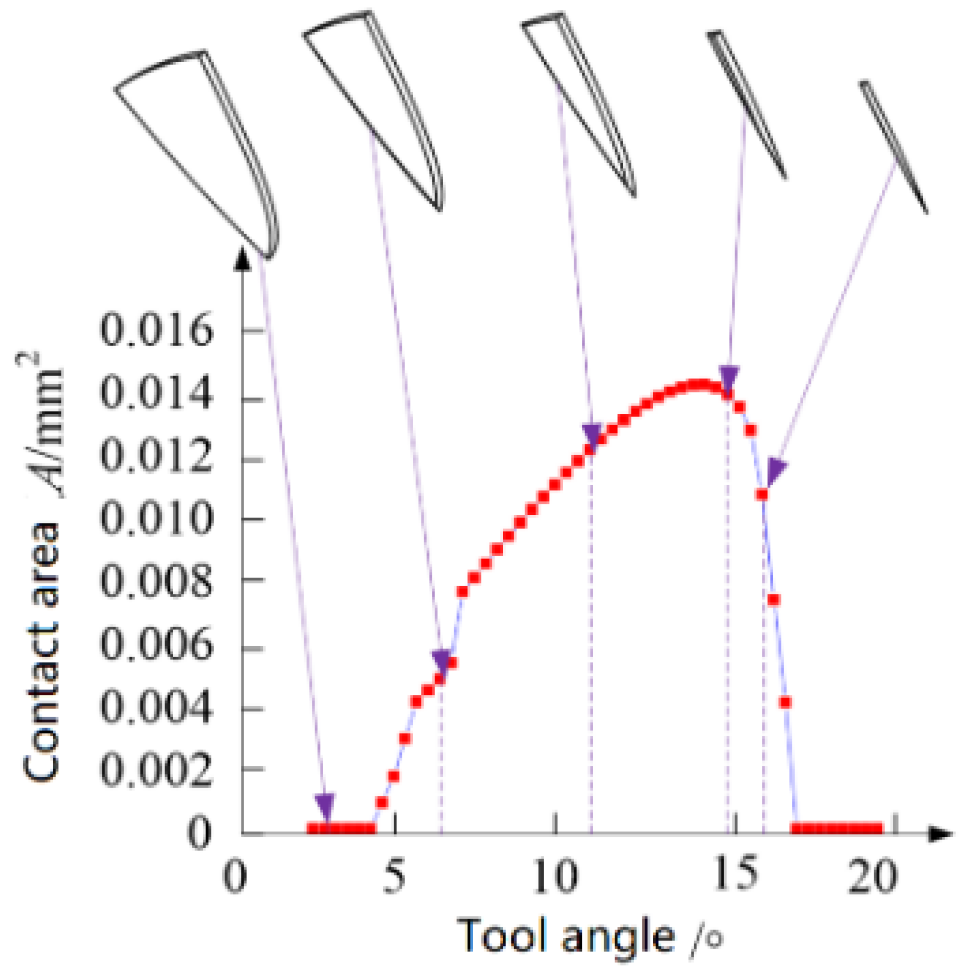
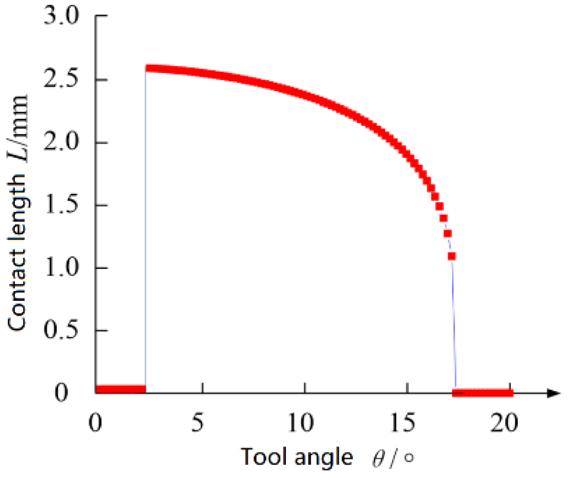
The parameters were set as the spindle speed of 7000 r/min, cutting depth of 0.3 mm, cutting width of 0.3 mm, feed per tooth of 0.1 mm/z, and inclination of the workpiece was 10°. Schematic diagram of the change of the insert-to-chip contact area at different corners of the tool is shown in
Figure 15. As the tool rotated, the contact area between the tool and the chip changed continuously. The length of the cutting edge, set as L, that participated in the cutting in different tool angles under this parameter is shown in
Figure 16.
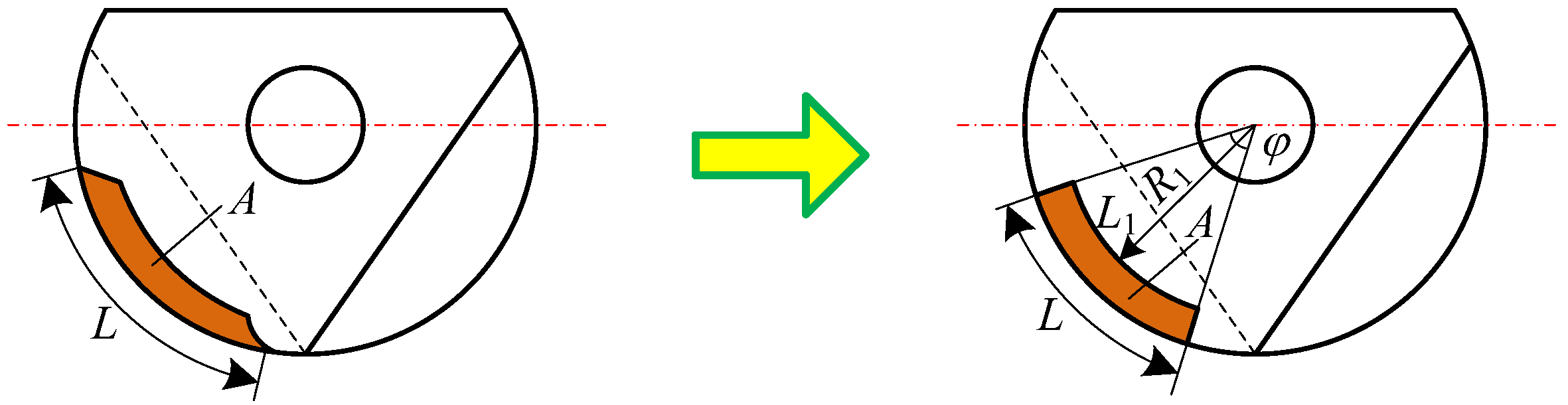
The model for the contact area of the chip at any time can be simplified, as shown in
Figure 17.
The following formula can be obtained from
Figure 18:
where
A represents the contact area of the tool and workpiece,
R1 represents the inner radius of the chip,
φ is the angle of the cutting-edge contact position.
L1 represents the inner length of the chip after simplification.
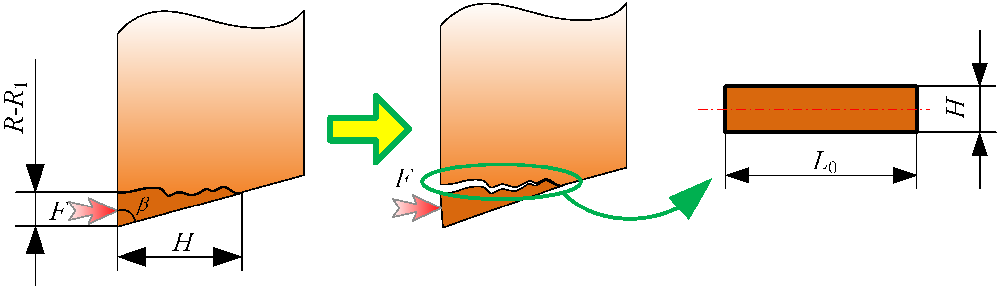
Figure 18 shows the damage of the tooltip during machining.
F is the radial force received by the tooltip.
The bending stress of the tool can be expressed by the following formula (5):
where
M is the bending moment, and
Z is the moment of inertia.
Therefore, to avoid low-speed impact damage in the PCBN tool interrupted cutting process, the critical conditions are
where
σf max is the limit of bending strength.
By substituting Equations (6)–(9) into Equation (5), the bending stress of the tool is
where
θ is the angle of the tool turns. When the angle of the tool is
θ at time
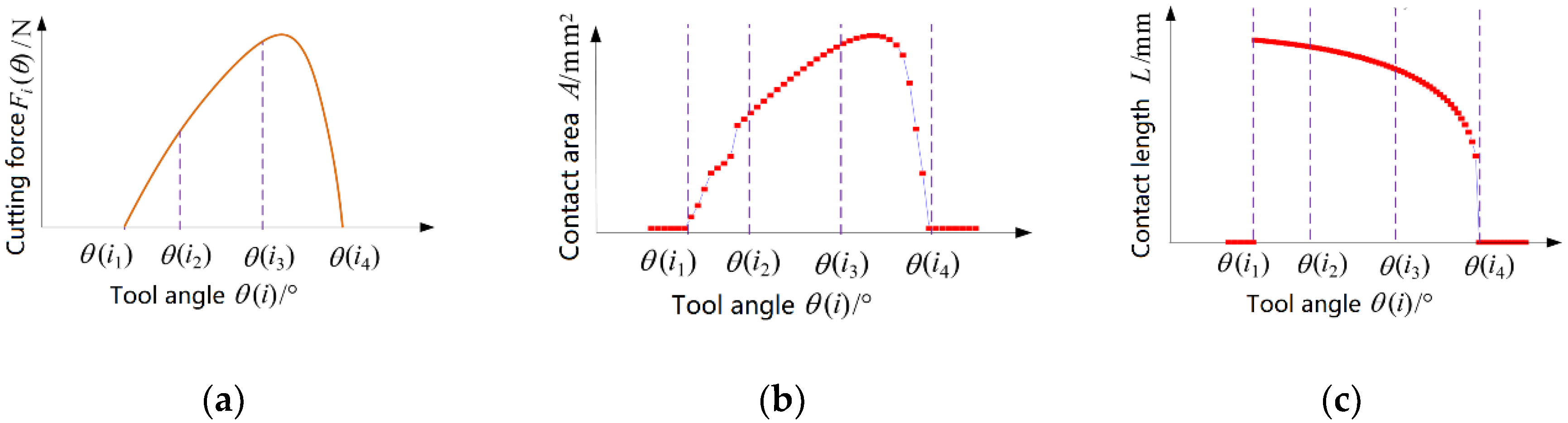
i, the bending stress of the tool is related to milling force, contact length, the contact area of the tool and the chip. And these parameters are related to the angle of the tool, cutting depth, cutting speed, cutting with, feed per tooth, tool parameters, etc., as shown in Equation (12). Where
Fi(θ) is the component of milling force perpendicular to the rake face when the angle of the tool is
θ. And it can be obtained by the cutting test or finite element simulation method. The length of the contact inserts
Li(θ), and contact area of tool and chip
Ai(θ) can be obtained using 3D modeling software. The relationship between these parameters and the tool angle are shown in
Figure 19. Therefore, the values of the three corners are brought into the Equation (11) to obtain the bending stress of the tool under the angle of rotation.
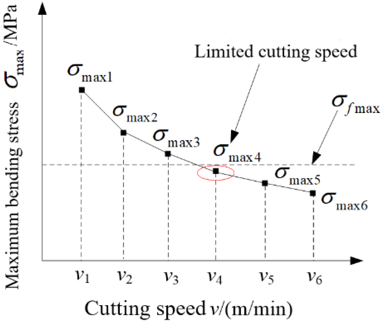
To avoid low-speed breakage, determine other parameters besides the milling speed, change the cutting speed, and obtain a maximum bending stress at each cutting speed, so that the maximum bending stress is less than the cutting speed value of the bending strength of the tool. The qualitative relationship between maximum bending stress and cutting speed is shown in
Figure 20.
In summary, by studying the influence of cutting speed on the failure of the hardened steel tool in the intermittent processing of PCBN tools, it was found that the main tool failure modes of the hardened steel of the PCBN tool are edge chipping, low-speed impact damage, flank wear, and high- speed fatigue damage. The early damage form was mainly the low-speed damage caused by large-scale damage of the flank face and shell-shaped damage of the rake face. When applying PCBN tools to hardened steel for milling, the early damage should be avoided as much as possible. To prevent premature damage, the following aspects should be taken: (1) The quenching hardness of the workpiece should be uniform, and the hard spots in the workpiece should be avoided as much as possible. (2) Avoid the milling speed that produced a low-speed breakage, so that the tool can be used within the safe milling speed range. (3) Try to ensure the grinding accuracy of the PCBN tool edge.
In future research, the suitable milling speed of the PCBN tool under different parameters can be quantitatively calculated by the combination of simulation and experiment. Moreover, other kinds of tools with different size or materials will be used to explore the applicability of the model. The results will provide a reference for tool design and process parameter Optimization.
Author Contributions
Conceptualization, X.W. and J.M.; Data curation, G.W. and X.Z.; Formal analysis, G.W. and J.M.; Funding acquisition, X.W.; Investigation, G.W. and X.W.; Methodology, G.W. and J.M.; Project administration, X.W.; Resources, G.W.; Supervision, X.W.; Visualization, X.Z.; Writing—original draft, G.W. and X.W.; Writing—review and editing, G.W., X.Z., X.W., and J.M.
Funding
This work was financially supported by the National Science Foundation of China (Grant No. 51575144) and Basic Research Projects of the “Science and Technology Talents” Program (LGYC2018JC042).
Conflicts of Interest
The authors declare no conflict of interest.
References
- Liu, X.; Jiang, Y.; Wu, S. Research on the Technical Progress of Milling for Hardened Steel Mould of Automotive Covering Parts. Chin. J. Mech. Eng. 2016, 52, 35–57. [Google Scholar] [CrossRef]
- Biondani, F.G.; Bissacco, G. Effect of cutting edge micro geometry on surface generation in ball end milling. CIRP Ann. 2019, 68, 571–574. [Google Scholar] [CrossRef]
- Kasim, M.S.; Hafiz, M.S.A.; Ghani, J.A.; Haron, C.H.C.; Izamshah, R.; Sundi, S.A.; Mohamed, S.B.; Othman, I.S. Investigation of surface topology in ball nose end milling process of Inconel 718. Wear 2018, 426–427, 1318–1326. [Google Scholar] [CrossRef]
- Urbikain, G.; de Lacalle, L.N.L. Modelling of surface roughness in inclined milling operations with circle-segment end mills. Simul. Modell. Pract. Theory 2018, 84, 161–176. [Google Scholar] [CrossRef]
- Pelayo, G.U. Modelling of static and dynamic milling forces in inclined operations with circle-segment end mills. Precis. Eng. 2019, 56, 123–135. [Google Scholar] [CrossRef]
- Nguyen, H.T.; Hsu, Q.C. Surface Roughness Analysis in the Hard Milling of JIS SKD61 Alloy Steel. Appl. Sci. 2016, 6, 172. [Google Scholar] [CrossRef]
- Tsai, M.Y.; Chang, C.T.; Ho, J.K. The Machining of Hard Mold Steel by Ultrasonic Assisted End Milling. Appl. Sci. 2016, 6, 373. [Google Scholar] [CrossRef]
- Luo, M.; Luo, H.; Zhang, D.; Tang, K. Improving tool life in multi-axis milling of Ni-based superalloy with ball-end cutter based on the active cutting edge shift strategy. J. Mater. Process. Technol. 2018, 252, 105–115. [Google Scholar] [CrossRef]
- Yıldırım, Ç.V.; Kıvak, T.; Erzincanlı, F. Tool wear and surface roughness analysis in milling with ceramic tools of Waspaloy: A comparison of machining performance with different cooling methods. J. Brazilian Soc. Mech. Sci. Eng. 2019, 41, 83. [Google Scholar] [CrossRef]
- Hegab, H.; Umer, U.; Soliman, M.; Kishawy, H.A. Effects of nano-cutting fluids on tool performance and chip morphology during machining Inconel 718. Int. J. Adv. Manuf. Technol. 2018, 96, 3449–3458. [Google Scholar] [CrossRef]
- Ghani, M.; Abukhshim, N.; Sheikh, M. An investigation of heat partition and tool wear in hard turning of HI3 tool steel with CBN cutting tools. Int. J. Adv. Manuf. Technol. 2008, 39, 874–888. [Google Scholar] [CrossRef]
- Liu, X.; Meng, A.; Chen, L. Critical Hardness when Hard-Dry Cutting GCr15. Chin. J. Mech. Eng. 2000, 36, 13–16. [Google Scholar] [CrossRef]
- Dureja, J.S.; Gupta, V.K.; Vishal, S.S. Optimization of flank wear and surface roughness for CBN-TiN tools during dry hard turning of hot work die steel. Indian J. Eng. Mat. Sci. 2010, 7, 129–147. [Google Scholar]
- Domenico, U.; Fabrizio, M.; Jawahir, I.S. The effects of cryogenic cooling on surface integrity in hard machining: A comparison with dry machining. CIRP Ann. Manuf. Technol. 2012, 61, 103–106. [Google Scholar]
- Lahiff, C.; Gordon, S.; Phelan, P. PCBN tool wear modes and mechanisms in finish hard turning. Robot. Comput.-Integr. Manuf. 2007, 23, 638–644. [Google Scholar] [CrossRef]
- Cantero, J.L.; Díaz-Álvarez, J.; Infante-García, D.; Rodríguez, M.; Criado, V. High Speed Finish Turning of Inconel 718 Using PCBN Tools under Dry Conditions. Metals 2018, 8, 192. [Google Scholar] [CrossRef]
- Díaz-Álvarez, J.; Criado, V.; Henar, M.; José, L.C. PCBN Performance in High Speed Finishing Turning of Inconel 718. Metals 2018, 8, 582. [Google Scholar] [CrossRef]
- Huang, Y.; Dawson, T. Tool crater wear depth modeling in CBN hard turning. Wear 2005, 258, 1455–1461. [Google Scholar] [CrossRef]
- Koshy, P.; Dewes, R.C.; Aspinwall, D.K. High speed end milling of hardened AISI D2 tool steel (58 HRC). J. Mater. Process. Technol. 2002, 127, 266–273. [Google Scholar] [CrossRef]
- Aslan, E. Experimental investigation of cutting tool performance in high speed cutting of hardened X210 Cr12 cold-work tool steel (62 HRC). Mater. Des. 2005, 26, 21–27. [Google Scholar] [CrossRef]
- Masato, O.; Akira, H.; Ryutaro, T.; Takashi, U. Cutting performance of PVD-coated carbide and CBN tools in hardmilling. Int. J. Mach. Tools Manuf. 2011, 51, 127–132. [Google Scholar]
- Bala, M.G.; Biswanath, M.; Sukamal, G. Experimental investigations while hard machining of DIEVAR tool steel (50 HRC). Int. J. Adv. Manuf. Technol. 2010, 51, 853–869. [Google Scholar]
- Wojciechowski, S.; Twardowski, P. Tool life and process dynamics in high speed ball end milling of hardened steel. Procedia. CIRP. 2012, 1, 289–294. [Google Scholar] [CrossRef]
- Wojciechowski, S.; Maruda, R.W.; Barrans, S.; Nieslonv, P.; Krolczyk, G.-M. Optimisation of machining parameters during ball end milling of hardened steel with various surface inclinations. Measurement 2017, 111, 18–28. [Google Scholar] [CrossRef] [Green Version]
- Wojciechowski, S.; Maruda, R.W.; Królczyk, G.M.; Niesłony, P. Application of signal to noise ratio and grey relational analysis to minimize forces and vibrations during precise ball end milling. Precis. Eng. 2018, 51, 582–596. [Google Scholar] [CrossRef]
- Fatih, T.; Oguz, C.; Mehmet, C.K. Investigation of TiN Coated CBN and CBN Cutting Tool Performance in Hard Milling Application. Chin. J. Mech. Eng. 2011, 5, 417–424. [Google Scholar]
- Chou, Y.K.; Evans, C.J. Cubic boron nitride tool wear in interrupted hard cutting. Wear 1999, 225–229, 234–245. [Google Scholar] [CrossRef]
- Chou, Y.K. Hard turning of M50 steel with different microstructures in continuous and intermittent cutting. Wear 2003, 255, 1388–1394. [Google Scholar] [CrossRef]
- Ko, T.J.; Kim, H.S. Surface integrity and machineability in intermittent hard turning. Int. J. Adv. Manuf. Technol. 2001, 18, 168–175. [Google Scholar] [CrossRef]
- Boing, D.; Schroeter, R.B.; Oliveira, A.J. Three-dimensional wear parameters and wear mechanisms in turning hardened steels with PCBN tools. Wear 2018, 398, 69–78. [Google Scholar] [CrossRef]
- Saketi, S.; Sveen, S.; Gunnarsson, S.; M’Saoubi, R.; Olsson, M. Wear of a high CBN content PCBN cutting tool during hard milling of powder metallurgy cold work tool steels. Wear 2015, 332–333, 752–761. [Google Scholar] [CrossRef]
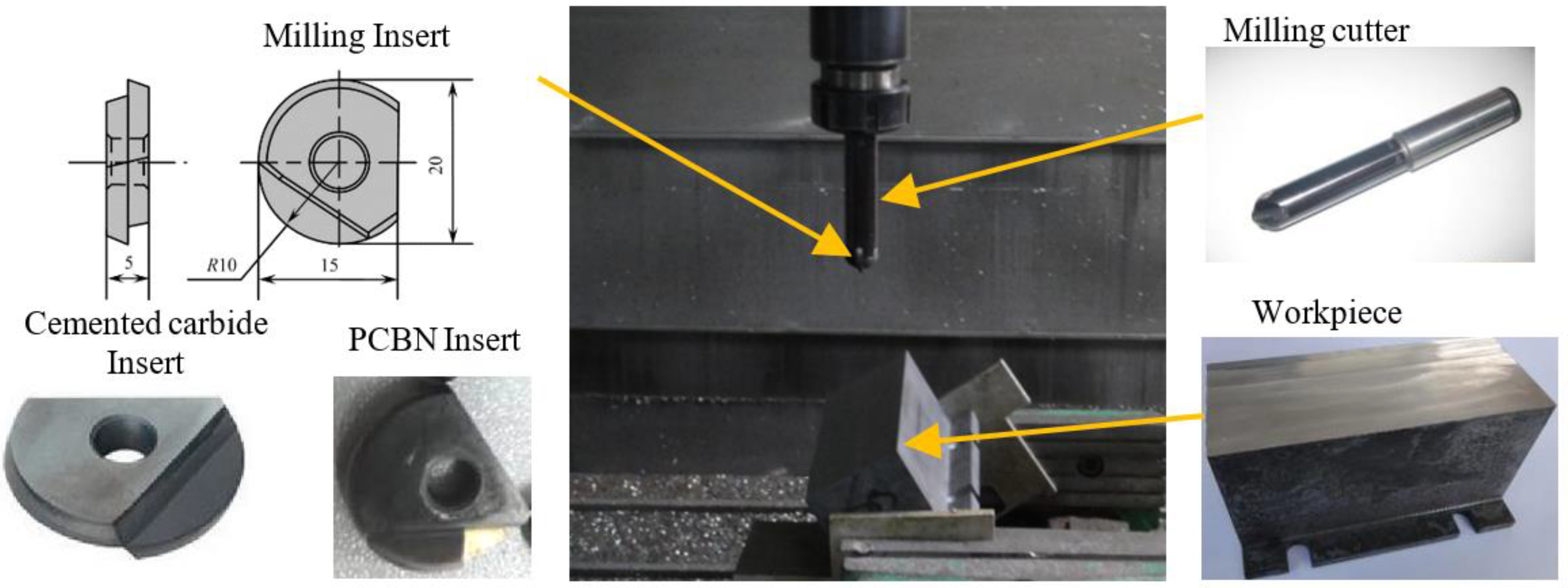
Figure 1.
The experimental setup for milling test.
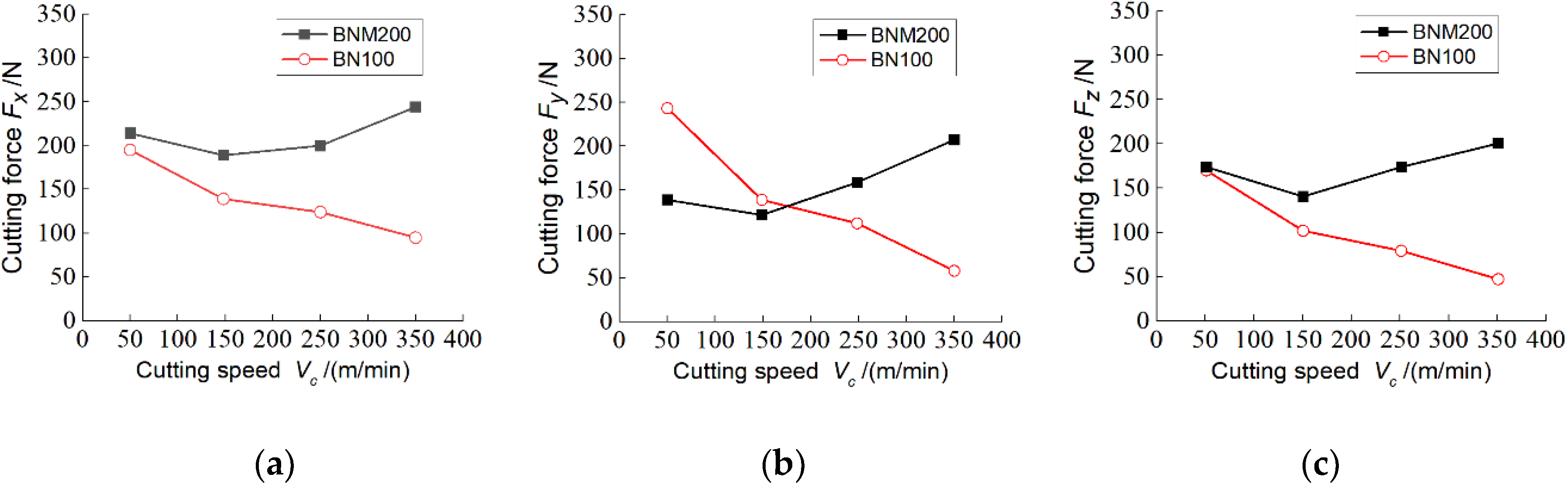
Figure 2.
Effect of cutting speed on cutting force: (a) Radial force; (b) Force in feed direction; (c) Axial force.
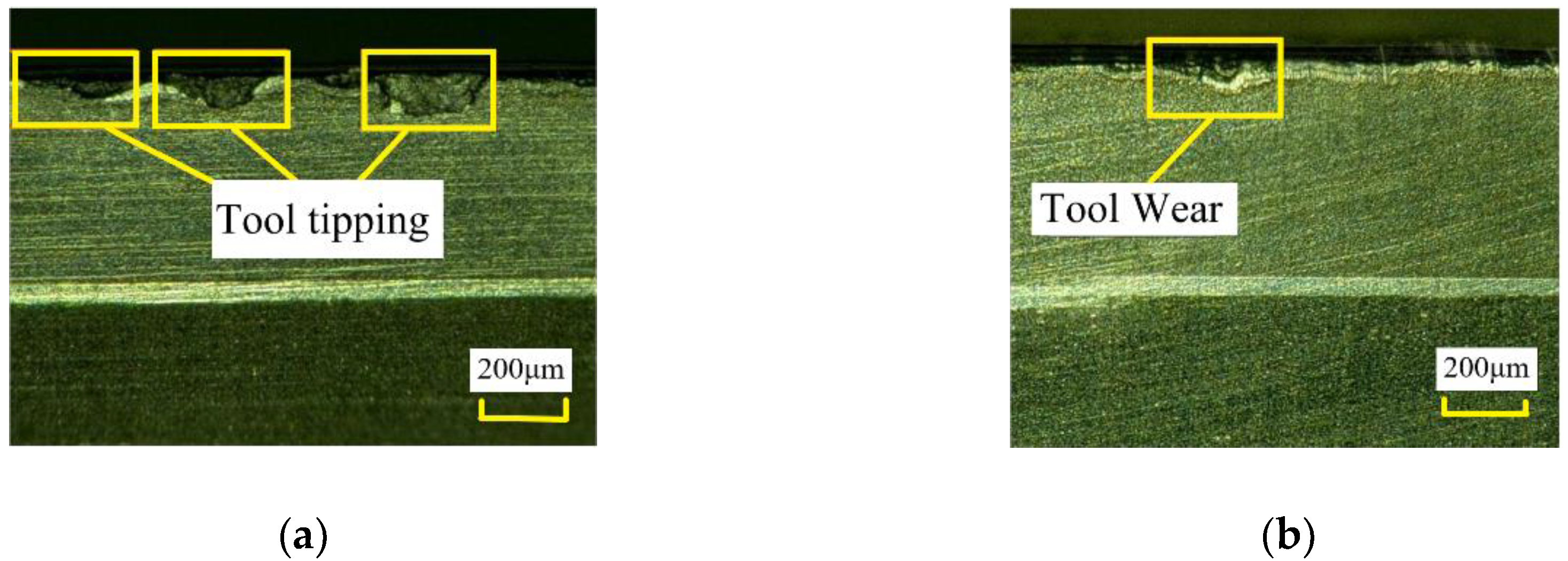
Figure 3.
Effect of chamfer width on resistant breakage ability of flank: (a) Chamfer width of 0.10 mm; (b) Chamfer width of 0.25 mm.
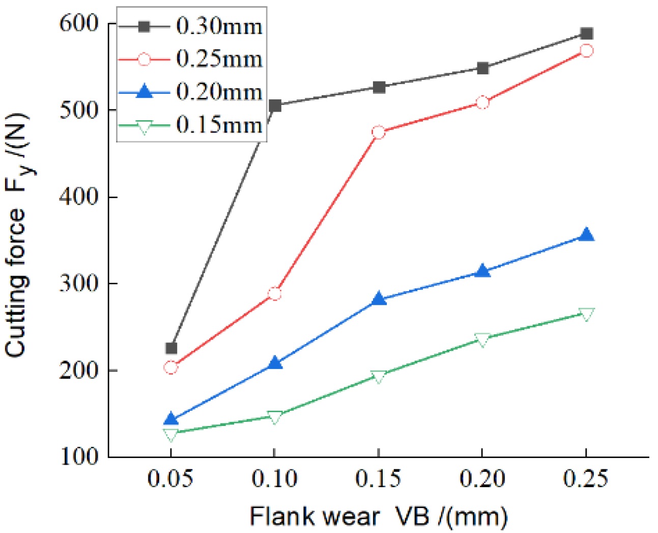
Figure 4.
Effect of chamfer width on cutting force under different tool wear.
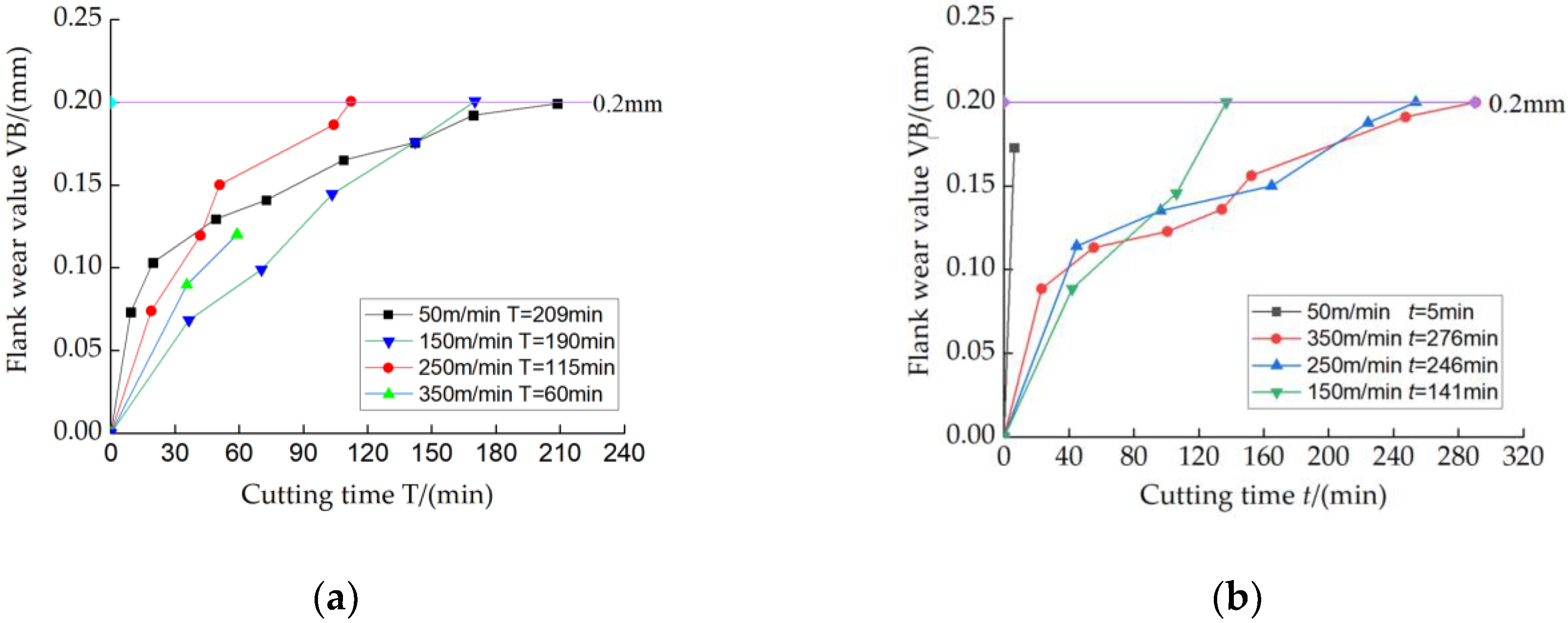
Figure 5.
Influence of cutting speed on tool wear: (a) Tool wear of cemented carbide tools (BNM 200); (b) Tool wear of polycrystalline cubic boron nitride (PCBN) cutting tools (BN 100).
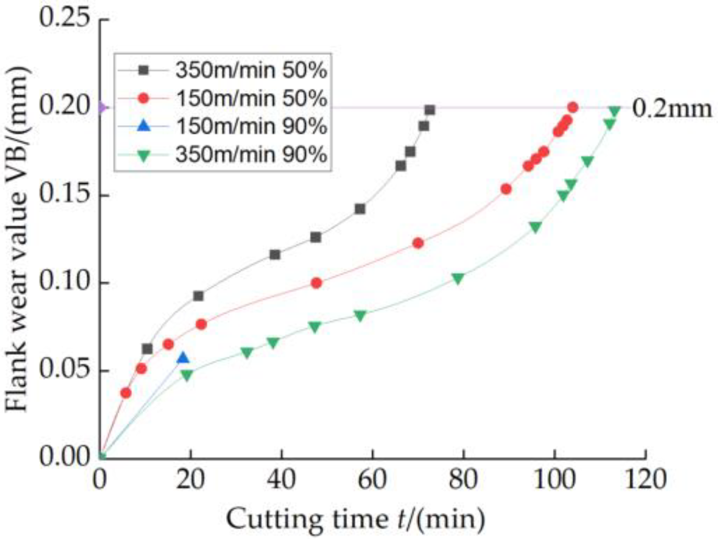
Figure 6.
Influence of CBN content on tool wear.
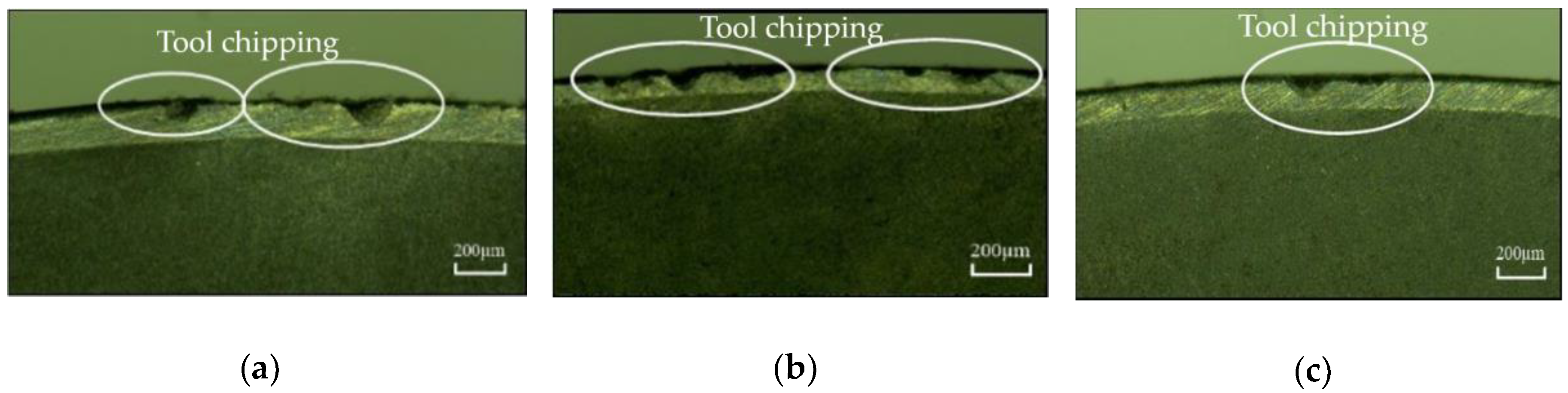
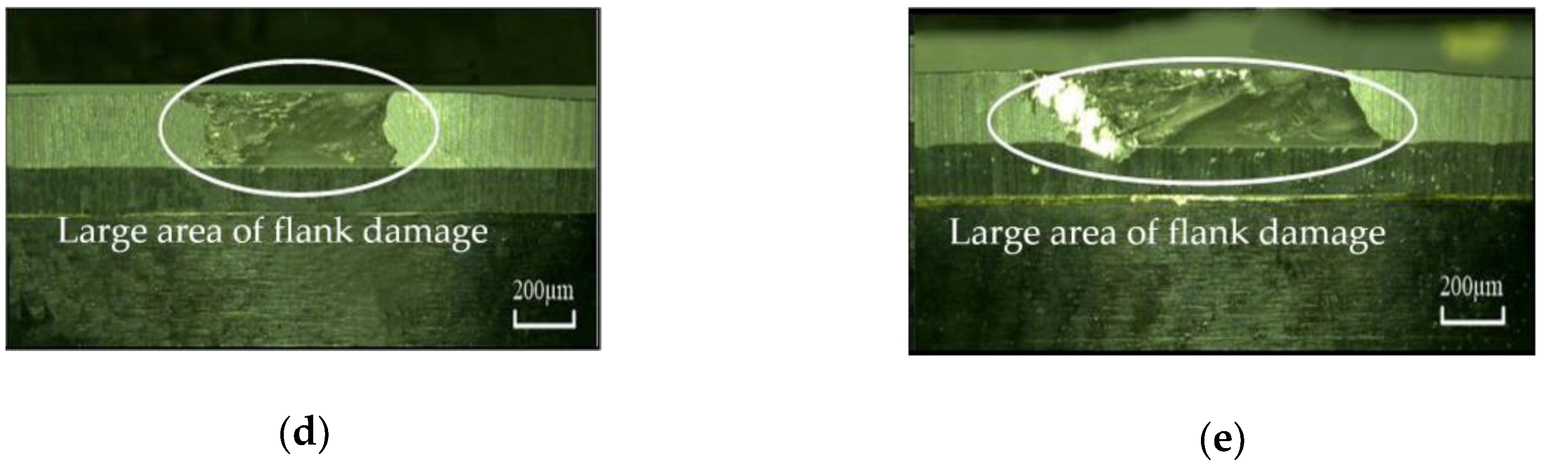
Figure 7.
Tool failure form at cutting speed 150 m/min: (a) t = 4 min (insert 1#); (b) t = 6 min (insert 2#); (c) t = 14 min (insert 3#); (d) t = 28 min (insert 4#); (e) t = 24 min (insert 5#).
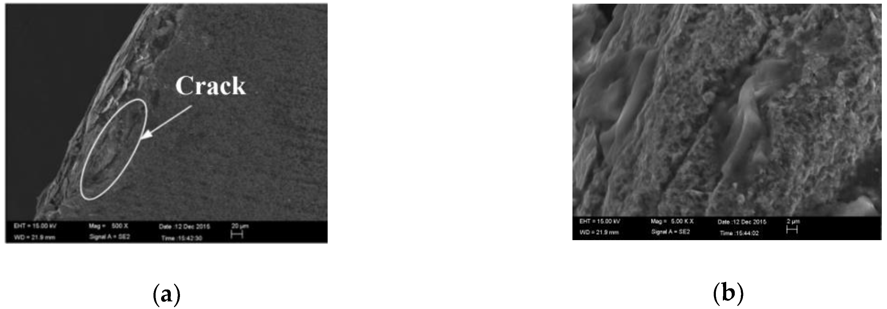
Figure 8.
The microscopic morphology of chipping: (a) The crack area; (b) The magnification of the crack.
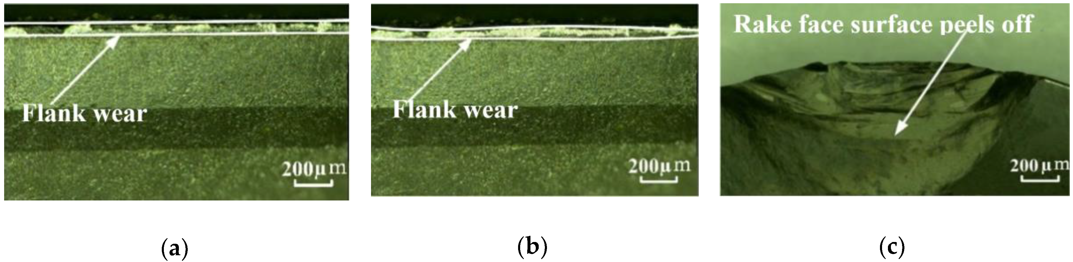
Figure 9.
Tool failure morphology of 6# cutter insert at different cutting times: (a) t = 32 min; (b) t = 56 min; (c) t = 58 min.
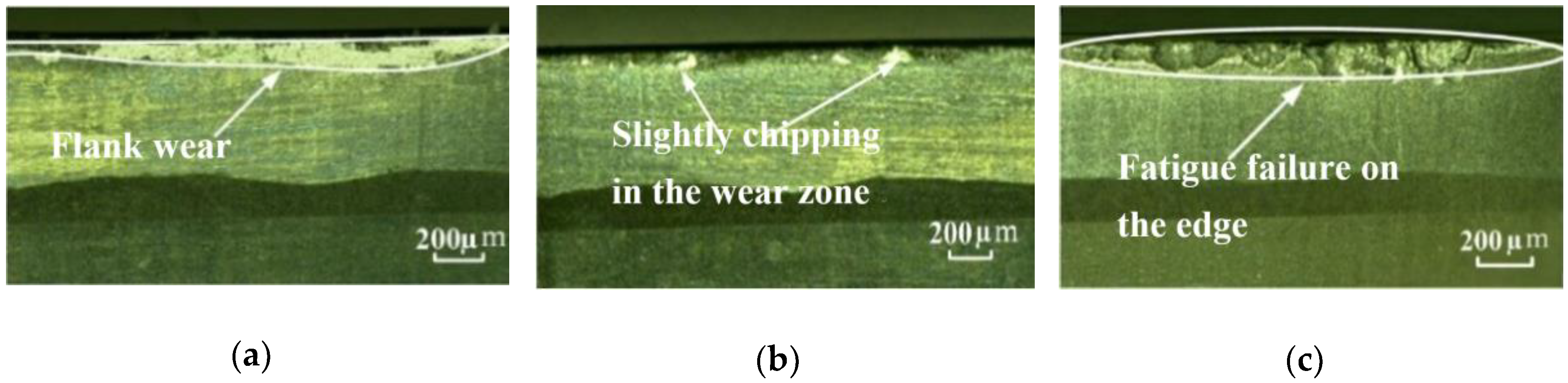
Figure 10.
Tool failure morphology of 7# cutter insert at different cutting times fatigue failure: (a) t = 18 min; (b) t = 68 min; (c) t = 84 min.
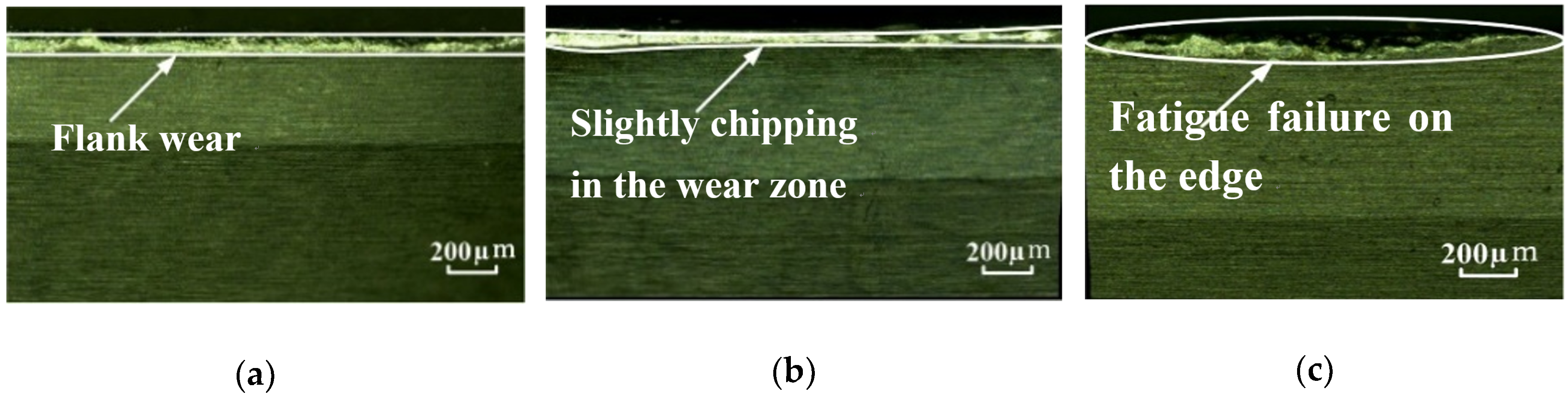
Figure 11.
Tool failure morphology of 8# cutter insert at different cutting times: (a) t =18 min; (b) t = 66 min; (c) t = 70 min.
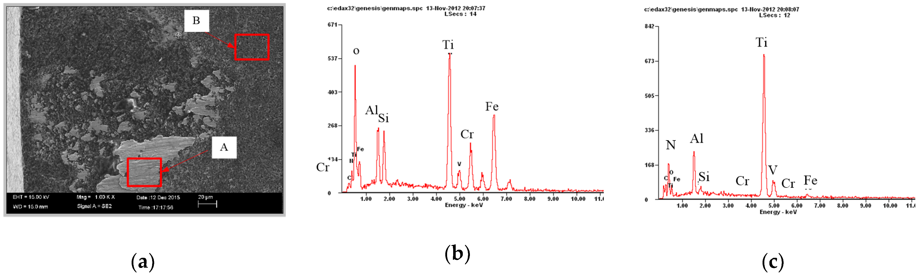
Figure 12.
PCBN cutting tool flank wear morphology: (a) The microstructure of the flank wear; (b) Analysis of element content at A; (c) Analysis of element content at B.
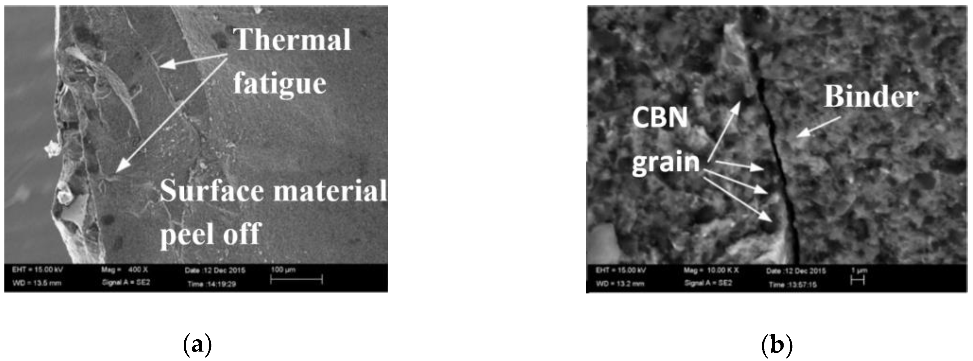
Figure 13.
The microscopic morphology of the PCBN tool rake face after the peeling of the surface material: (a) Microscopic morphology; (b) Tool rake face fatigue crack morphology.
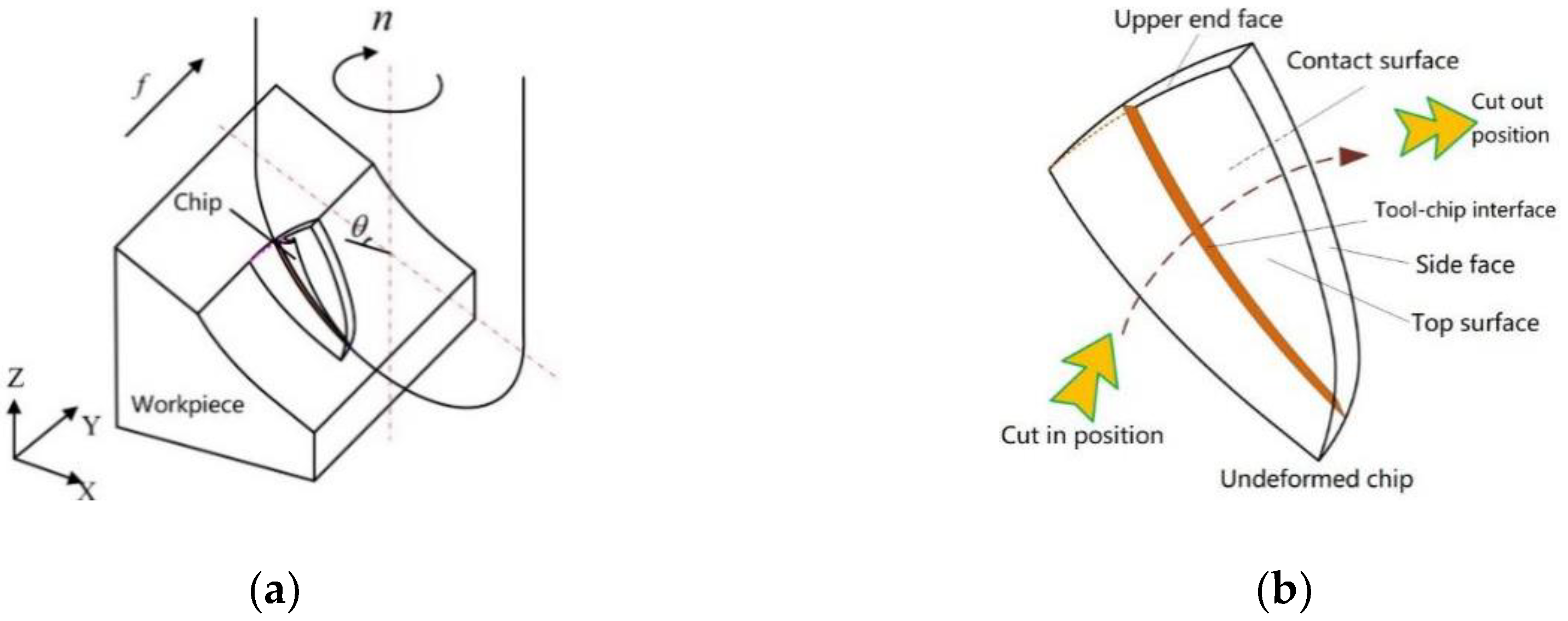
Figure 14.
Schematic diagram of the milling process: (a) Milling of Inclined Plane; (b) Schematic of chip shape.
Figure 15.
Cutting edge contact area in different tools angles.
Figure 16.
Cutting edge contact length in different tools angles.
Figure 17.
A simplified model of the tool–chip contact area.
Figure 18.
Schematic diagram of stress damage of cutting tool.
Figure 19.
Correspondence relationship in different tools angles between cutting prameters: (a) cutting force; (b) contact area; (c) contact edge length.
Figure 20.
Determination of limit cutting speed.
© 2019 by the authors. Licensee MDPI, Basel, Switzerland. This article is an open access article distributed under the terms and conditions of the Creative Commons Attribution (CC BY) license (http://creativecommons.org/licenses/by/4.0/).


