Article

Characterizing Stalagmites’ Eigenfrequencies by Combining In Situ Vibration Measurements and Finite Element Modeling Based on 3D Scans

1
Seismology-Gravimetry, Royal Observatory of Belgium, 1180 Brussels, Belgium
2
AGEs, Department of Geology, University of Liège, 4000 Liège, Belgium
3
Institute of Geology and Mineralogy, University of Cologne, 50674 Köln, Germany
4
Geology and Applied Geology, Faculty of Engineering, University of Mons,7000 Mons, Belgium
*
Author to whom correspondence should be addressed.
Geosciences 2020, 10(10), 418; https://doi.org/10.3390/geosciences10100418
Submission received: 14 September 2020 / Revised: 13 October 2020 / Accepted: 17 October 2020 / Published: 20 October 2020

Abstract

:
Broken or deformed speleothems have been used as indicators of paleo-earthquakes since the 1990s; however, a causal link is difficult to prove except for some thin speleothems. In contrast, the presence of intact speleothems permits estimating an upper limit of the level of horizontal ground motions of past seismicity in the area. The natural frequencies of speleothems are fundamental parameters for their response to earthquakes. This study proposes a new method of in situ characterization of these natural frequencies. Tested in the Han-sur-Lesse cave (Belgian Ardennes), the method is based on recording the ambient seismic noise using three-component sensors on a stalagmite and a 3D laser scan of its shape. The ambient seismic noise records allow a precise determination of the eigenfrequencies of the stalagmite. In addition, numerical models based on the 3D scan show good consistency between measured and modeled data. The joint analysis of these two techniques concludes that the shape of the stalagmite (elliptical cross-section and shape irregularities) influence the eigenfrequencies and polarization of the modes while also causing a near-orthogonal split of natural frequencies. The motions recorded on the stalagmite show significant amplification compared to those recorded at the free surface outside the cave, which has a strong impact on seismic hazard assessment based on speleothems.

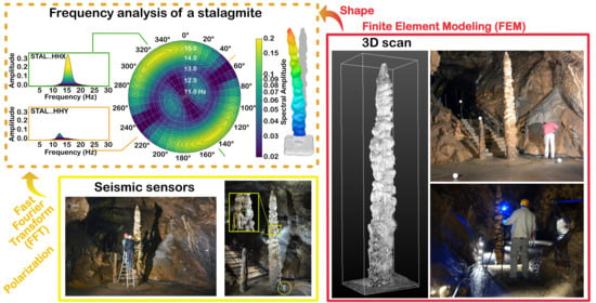
Graphical Abstract

1. Introduction

The observation and dating of broken or deformed speleothems have been used as indicators of paleo-earthquakes since the 1990s (see [1,2] for a review). However, the causal link between earthquakes or tectonic movement and growth, fracturing, breaking or tilting of speleothems is often difficult to prove because different phenomena such as frost, water flow, or ground instability are susceptible to producing similar effects (e.g., [2,3,4,5,6,7,8]). On one hand, numerical models and physical experiments pointed out the limits of testing the earthquake hypothesis to explain broken speleothems [9,10] except for very thin stalagmites or stalactites (such as soda straws). On another hand, so far, such models do not take into account all possible imperfections and weaknesses in the body of the speleothems. In addition, broken speleothems can be used to date ceiling collapses that sometimes can be related to paleo-earthquakes [11].
In contrast, the presence of intact speleothems indicates that, considering their growth, no earthquake-driven ground motions were sufficiently large to break them. Hence, knowing the speleothem’s characteristics allows estimating an upper limit on past horizontal ground motions that did not result in the failure of studied speleothems [12,13,14,15,16,17,18,19,20]. This information provides an important view in the past seismicity in the area where the cave is located. In addition, it provides a ground motion level directly comparable to results of seismic hazard evaluation and of ground motion modeling for near historical earthquakes similar to the concept of precariously balanced rocks (e.g., [21]) or precariously balance archaeological objects [22].
The natural frequency and damping factor of the speleothems are fundamental parameters in the study of their response to seismic shaking. With an eigenfrequency in the range of moderate local (1–20 Hz) or larger remote earthquakes (0.1–10 Hz), earthquake ground motions can cause resonance of the speleothem. Their failure can occur at a lower acceleration than predicted by static methods. The in situ study of the natural frequency of speleothems has been done with a laser interferometer [23,24] or with a geophone attached to the stalagmite [13,14,15,16,17,19]. In those experiments, the stalagmite was slightly excited using a finger or a rubber hammer. Some studies [10,14,15,16,23] of intact speleothems showed the link between the natural resonance frequency and the shape (type and length) of the speleothems. A link between damping value and the type of connection to the base rock was reported by Lacave et al. [10,23]. Modeling of the frequency of stalagmites for simplified and approximate shape has also been done [9,12,20] and have shown that in addition to the mechanical properties, the shape of the stalagmite influences the natural frequencies decisively. An appropriate way to explore the shape of the stalagmite is to perform a 3D laser scan. The use of 3D scans has already proven its effectiveness for the characterization of speleothems in caves. Such an approach does not disturb the environment, allow a large sampling of the population of speleothems, and it permits the extraction of geomorphological information such as displacement of the growth axis [25,26,27].
In this study, a new method of in situ characterization of the natural frequency of stalagmites is proposed. The ambient seismic noise (i.e., the permanent vibration of the ground surface with different origins depending on the frequency band such as human activities, microseisms, oceanic sources, local weather condition) was recorded using three-component sensors in the cave and on stalagmites during 22 days first to identify the natural frequency of the stalagmites. The relative amplification of motions between the stalagmite, its base, and the free surface outside the cave are evaluated. The measured natural frequencies are compared with numerical models based on the 3D scan of the stalagmite; this allows determining the influence of the complexity of its shape on the natural frequencies.

2. Materials and Methods

2.1. Study Site—Karst System of Han-Sur-Lesse

The target of the investigation was a characteristic stalagmite in the Han-sur-Lesse cave called “The Minaret”. The karstic system of Han-sur-Lesse is situated in the SSE of Belgium and one of the longest cave systems in Belgium. It is an underground cut-off meander of the Lesse River in the Givetian limestone (Figure 1). This system is the result of two genetic phases [28,29,30,31]. First, during the second part of the Mesozoic (Cretaceous, tropical climate), the partial dissolution of limestone occurred leading to “ghost rock”, a very porous matrix in place constituted by the retention on-site of residual insoluble phases [29,32,33]. In the second phase, during the Neogene, an uplift of the high plateaus of Belgium led to the incision of epigenetic rivers, which cross the different geological lithologies. Then, the digging of the valleys allowed rivers to meet the “ghost rock” and to excavate them, forming the speleological caves. Today, this system is still evolving (e.g., new dissolution, alluvium deposition, enlargement by collapses, formation, and growth of speleothems). The sedimentary serial in the Vervietois gallery is a good indicator of this past evolution [31].
The Minaret room is located in a little depressed area of this gallery. Based on the aerial LIDAR topography data (from the SPW, Service Public de Wallonie) and the topography of the cave, the depth of this gallery varies from 60 to 80 m from the ground surface (with the deepest part for the Minaret room). The deepest dry galleries and rooms are located at around 90–100 m from the surface.
The Han-sur-Lesse cave is situated at a distance of ≈50–60 km from the Lower Rhine Embayment, which is the most seismically active area in northwestern Europe [34]. The closest seismic activity to the site originates from the eastern part of the Ardenne at a distance of 30 km. The strongest known earthquake in this area is the MW ≈6.0 18 September 1692 Verviers earthquake [35]. Likely, two moderate regional earthquakes (23 February 1828 and 8 November 1983) initiated two important roof collapses in the cave [11], while the 1692 earthquake triggered a slope movement at the place where the Lesse river leaves the cave [36].

2.2. Non-Destructive Characterization of the Stalagmite

2.2.1. Shape: 3D Laser Scan of the Minaret Stalagmite

A 3D laser scan of the Minaret stalagmite was realized to capture its shape. The equipment used was a FARO Focus 3D infrared phase scanner capable of covering distances up to 154 m. The registration of individual scans was based on plastic spheres and some extra golf balls (Figure 2). An internal compass and electronic leveling data were used during the registration. A medium resolution was chosen and the color option for the scanning was not used, resulting in about a 10-min time per scan, which was adapted to the length of the time between two visiting groups. The median point error of the registration is estimated to be smaller than 6.4 mm.
The initial filtering and registration were made with the FARO Scene software (commercial version 2019.2). For the filtering of the raw data, Filter Edge Artifact (Intelligent Streak) and Filter Stray with a stray parameter of 0.0250 m were used. Further analyses, particularly slices and surface reconstruction, were made with CloudCompare (open source software, [40]). Surface reconstruction, which is required for the construction of Finite Element Models of the stalagmites, was calculated from the point cloud by meshing algorithms. The Poisson Reconstruction plugin of CloudCompare was used at two different octree levels (8 and 12). The higher resolution of octree level 12 gives a more detailed 3D model, but for the 3D Finite Element modeling, the lower resolution (here octree 8) represents a compromise between accuracy and computational complexity. A lower level (e.g., 5) would not give a sufficient reconstruction of the geometry.
Finally, the resulting point clouds were analyzed in Autodesk Fusion360 (Education Version 2.0.8749) to characterize the stalagmite and extract geomorphological information. Vertical and horizontal sections were extracted from the mesh cloud point. The best ellipse is searched for in each horizontal cross-section separated vertically by 5 cm using the EllipseModel method of scikit-image processing toolbox [41] based on least-squares fitting of ellipses [42]. The stalagmite is characterized [25,26] by:
  • Elevation (vertical distance between the base and the head)
  • Major (a) and minor (b) axes of each ellipse
  • Coordinates (X, Y, Z) of the center of each ellipse
  • Orientation of each ellipse (major axes (a) with respect to the north)
  • Geodesic distance (sum of the distances between two centers of consecutive ellipses)
  • Project distance—horizontal displacement (center of the base ellipse to the center of the head ellipse)
  • Angle of the horizontal displacement (with respect to the north)
The combination of these parameters permits quantifying the shape of the stalagmite and its variation to create a model of the stalagmite based on elliptical cross-sections (Section 2.3.2) but also to choose the geometrical parameters for the analytical analysis (Section 2.3.1).

2.2.2. Natural Frequency: Seismic Measurements

To estimate the natural frequencies of the stalagmite, only ambient seismic noise was recorded; no forced vibration was used. For the first time, this technique permits the continuous monitoring of the stalagmite’s motion during 22 days.
The horizontal and vertical stalagmite motions were registered with a three-component 5 Hz-Smartsolo sensors designed by Dynamic Technologies (DTCC). This sensor is an integrated high-sensitivity geophone (76.7 V/m/s) that is light-weight (1.7 kg) and has an adaptable preamplifier gain that was fixed to 36 dB (maximum) for this study. The sampling rate of the acquisition was 250 Hz, and a low-cut filter was disabled.
The ambient seismic noise measurement of the Minaret stalagmite lasted 22 days of continuous recordings between 7 and 30 January 2020 (limited by the battery capacity). During this period of the year, the touristic cave is traditionally closed to the public, which prevents anthropogenic noise linked to visitors.
Two sensors were placed in the cave (Figure 3a): one attached with a ratchet strap to the Minaret stalagmite and another one placed on the ground near the stalagmite. As the Minaret stalagmite is one of the most important attractions in the cave, special care had to be taken to avoid any damage by placing a sensor on the structure; therefore, placing the sensor of 1.7 kg at the top was not an option. As a compromise, the spot was identified at an elevation of 2.52 m above the floor, where a flat surface of the stalagmite’s flank allowed the sensor to be well coupled and not tilted. The presence of the two sensors in the room allows obtaining the response of the stalagmite by deconvolution (stalagmite signal divided by the signal of the ground). A third sensor (Figure 3b) was placed at the surface (outside the cave) at a location vertically above the stalagmite (Figure 3c). This sensor was buried in the top-soil to improve the coupling and reduce noise.
Spectral analysis of the seismic records was achieved by moving windows of 30 min length. For each window, a Fast Fourier Transform [43] was computed, and the resulting frequency spectra were smoothed by a Konno and Ohmachi [44] smoothing filter of 40%. An average of all the windows for each component was calculated. The amplitude distribution of the frequency in the horizontal plane as a function of the azimuth was implemented in a polar graphic with HVSR_to_virtual_borehole code [45]. This azimuthal dependency of the vibrations is crucial to understand the potential link between the frequency and the shape of the stalagmite.
A deconvolution was made between the stalagmite and the cave ground signal to obtain the response of the stalagmite. The same can be done between the cave ground and the surface to characterize the specific spectral amplitudes of the cave room.

2.2.3. Mechanical Properties

Natural frequency is directly related to mechanical properties. Those parameters are essential for modeling. As it was not possible to perform laboratory tests on samples from the Minaret stalagmite, material properties were taken from similar structures obtained in the Hotton cave, which is a Belgian cave in the same geological formation. The young’s modulus of the stalagmites is 22,000 MPa, and their density is 2500 kg/m³. A detailed description of these tests is available in Cadorin et al. [9]. It is important to note that the Poisson’s ratio is not available in this study, so a Poisson’s ratio of 0.25, which corresponds to a perfect isotropic elastic material, is used. In addition to this, another Poisson’s ratio of 0.1 is used, and this was obtained from the study of stalagmites by Gribovszki et al. [20].

2.3. Modeling of the Natural Frequencies

2.3.1. Analytical Method

To have a first idea of the natural frequency of the stalagmite, an analytical approach was performed. Here, the stalagmite is considered as a perfect cylinder (constant diameter) without internal heterogeneity (e.g., anisotropy, density variation). The created cylinder beam is fixed at the bottom and free at the top (boundary condition for a cantilever beam). In this simplified case, analytical equations can be deduced from cantilever beam theory for free vibration, which is a specific case of the Euler–Bernoulli theory. The natural frequency of the stalagmite depends on its height (H), diameter (D), density ( ρ ), and its Young’s modulus (E). In general, the natural frequency is obtained by Equation (1) (for detail developments, see e.g., [46]):
f i = ω i 2 π = α i 2 2 π I   E A   ρ   H 4 ,
with:
  • A, the area of the cross-section of the cylinder
  • I, the moment of inertia of the cross-section
  • ω i , the angular frequency
  • α i , a correction parameter that corresponds to each mode of frequency (i = 1,2,3 …)
α i = 1.875,4.694,7.855,10.996,14.137 for i = 1, 2, 3, 4 and 5
If a cylinder is chosen, A = π D 2 4 and = π   D 4 64 . Therefore Equation (1) becomes Equation (2):
f i =   α i 2 2 π D 2   E 16   ρ   H 4   .
Note that this analytical approach requires strong simplifications concerning the geometry of the stalagmite as an assumption of constant cross-sections and homogeneity. This induced some inaccuracies in the results. If the basic geometry is complex, as it is the case of the Minaret stalagmite, a more refined approach (e.g., Finite Element Model) might be necessary.

2.3.2. Finite Element Model (FEM)

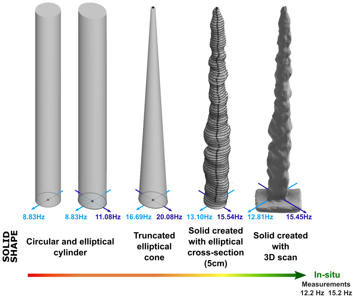
The 3D laser scan model of the stalagmite was used to produce a Finite Element Model (FEM). This technique was suggested by Gribovszki et al. [20] and recently used to model the seismic capacity of stalagmites [47]. To estimate the influence of shape complexity and resolution, four simpler FEM of the same size as the stalagmite were used. All five FEM with increasing degrees of resolution of the Minaret stalagmite were created in Fusion360: i.e., a simple circular cylinder, an elliptical cylinder, a truncated elliptical cone, a solid based on elliptical cross-sections spaced by 5 cm, and another based on the 3D laser scan.
For the FEM based on the 3D laser scan, the mesh model of the stalagmite (99,200 faces) based on the subsampled point cloud of the 3D laser scan (obtained after the procedures explained in Section 2.2.1) was added in Autodesk Fusion360 and converted in a solid body (B-rep) to define an FEM of the stalagmite.
For the FEM based on elliptical cross-sections spaced by 5 cm, 90 ellipses spaced 5 cm apart and a summit point were used. These correspond to the elliptical cross-sections deduced from the 3D scan (Section 2.2.1). The solid body on which the FEM is performed was created with a smooth shape that transitions between the sections. The same technique was used for the truncated elliptical cone.
For all these models, a fixed constraint boundary condition was used for the base of the solid body. This condition is particularly well adapted to the Minaret stalagmite case; the stalagmite’s base is encased in a concrete slab following the touristic development of the cave. The mechanical properties of the stalagmite were added to this model (Young’s modulus, density, Poisson’s ratio) based on published data. The effect of variations of these properties on the dynamic characteristics of the structure was tested. In a final step, the solid body was meshed. The parabolic element order was chosen with possible curved mesh elements, which allows a more precise representation of the curved surface of the initial model. In Fusion360, this requires the selection of several parameters that define the coarseness and the dimensioning of the mesh [48]:
  • The average element size that specifies the element size relative to the model size.
  • The minimum element size relative to the average size. This setting allows automatic refinement in small areas.
  • Maximum turn angle, which affects the number of elements on curved surfaces. The smaller the angle, the greater the number of meshes on a curve.
  • The adjacent mesh size ratio, which parameterizes the transitions between fine and coarse meshes.
  • The aspect ratio (ratio of longest to shortest dimension).
As smaller mesh elements require longer simulation times, a compromise between resolution and calculation effort is necessary. Table 1 lists the size and parameters for these models. Finally, a modal analysis was done to estimate the natural frequencies of the stalagmite, visualize the mode shape, and determine the mass participation factor for each mode and axis.

3. Results

3.1. Seismic Measurement

The natural frequencies of the stalagmites could be identified from the ambient seismic noise and were stable over the entire measurement period. However, the amplitudes change particularly between 1.5 and 25 Hz due to the changes in anthropogenic noise. They are higher during daytime than at night and on weekdays compared to the weekend (Figure 4). The stalagmite motions (STAL) are larger compared to the motions measured at its base (SOIL) and at the surface outside the cave (SURF); however, there is no evidence for the nonlinearity of the amplification (Figure 4).
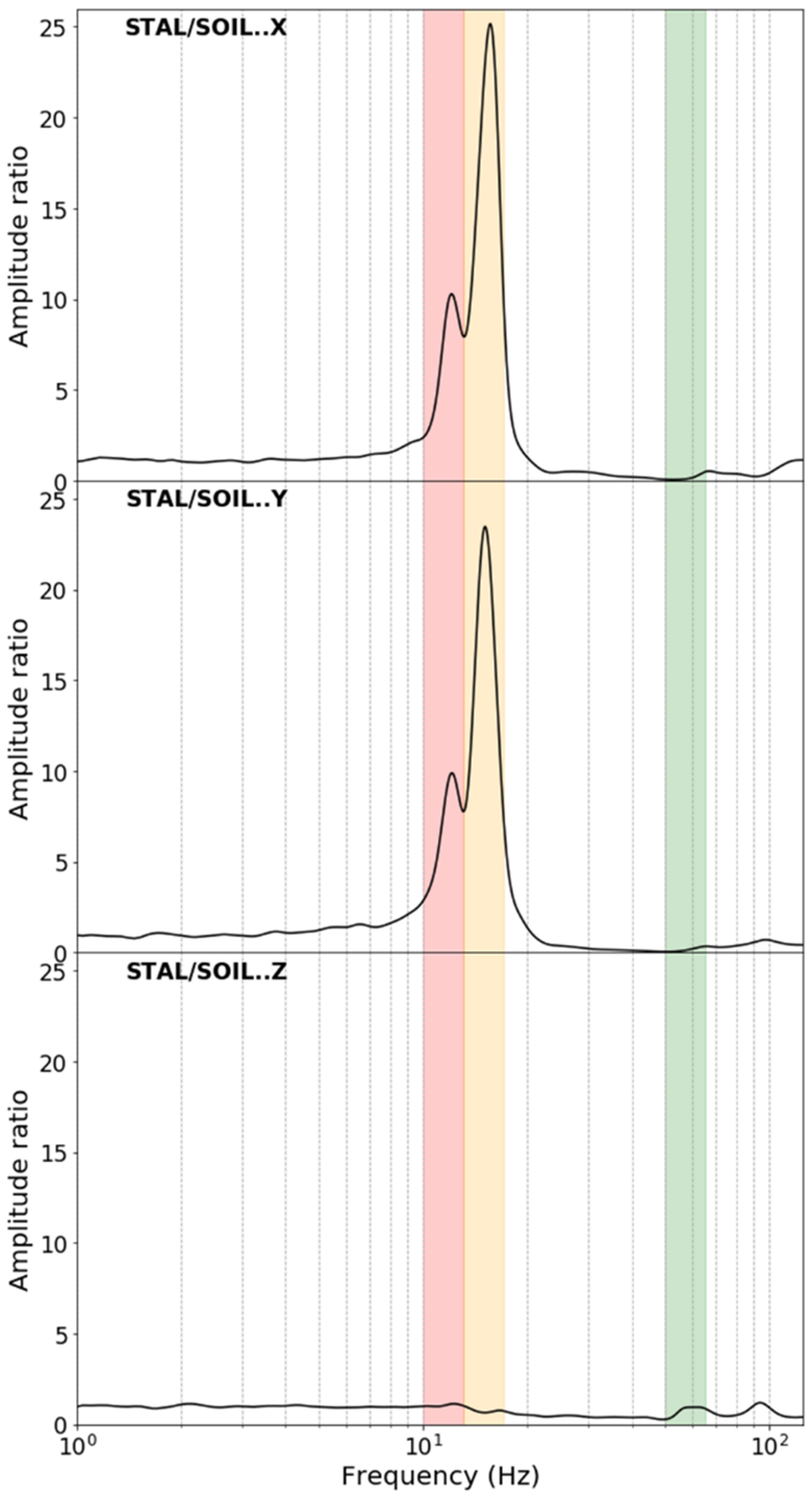
The result of the spectral analysis of the dataset is shown in Figure 5. The largest spectral amplitudes are in the 10–20 Hz range at 12.2 Hz and 15.2 Hz with the largest spectral amplitude at 15.2 Hz. These eigenfrequencies are only identified on the horizontal components and are stable in time (standard deviation of 0.06 Hz). A second set of peaks in the spectral amplitudes exists at 57 and 64 Hz, and it is best visible in the vertical component; however, it has much lower values than the previous ones. They seem to regroup into a single spread peak when a Konno and Ohmachi smoothing is applied. When the signal from the stalagmite is deconvolved by the signal recorded at the cave ground, these peaks almost disappear. This study concentrates on frequencies below 20 Hz relevant for earthquake studies. A small peak is identified at 50 Hz, and it is probably related to the electrical installations of the cave.
The two spectral peaks at 12.2 and 15.2 Hz have perpendicular polarizations, as shown in Figure 6 with azimuths at N52° E and N142° E. For much lower intensity frequencies located in the 55–65 Hz zone, the same observation can be made if the data are not smoothed beforehand. The directions are still perpendicular but offset by about 10° (N65° E, N155° E).
The observation of an almost perpendicular polarization (Figure 6) shows the importance of studying the horizontal motions in more detail. Motions observed on the stalagmite (STAL) are set in relation to those recorded at its base (SOIL) or at the surface (SURF) (Figure 4). In addition to some scatter, a linear correlation exists between the displacement amplitudes recorded by sensors for the X and Y components (Figure 4). The mean ratio between SURF and SOIL amplitudes is close to 2.0, which might be due to the free surface effect at SURF. The relative amplification of STAL compared to SOIL is 21 and 13 times for the X and Y components, respectively. Comparing the motion of the stalagmite to that at the surface brings those numbers to 14 and 4, respectively. All correlations indicate a linear relationship between the amplitudes of the displacement and highlight that, for frequencies between 11 and 16 Hz and amplitudes between 0 and 0.013 nm, there are no signs of nonlinearity.

3.2. 3D Laser Scan

3.2.1. Shape of the Stalagmite

The 3D laser scan of the stalagmite allowed considering its irregular shape and studying its effects on the calculated eigenfrequencies. The height of the stalagmite (above the concrete encasing its base) is 4.5 m. Its cross-section decreases upward (Figure 7a, Figure 8). The position of the center of the ellipses varies in space (Figure 8). Between the center of the base ellipse and the top, a lateral offset of 12 cm exists in the direction of 18 ° west; the center of the top ellipse is offset 11 cm at 14 ° west (Figure 7b).
The shape of the sections (vertically separated by 5 cm) varies from strong elliptical to almost circular. The major on minor axis report (a/b) ranges from 1.65 (ellipse) to 1.02 (circle) with a clear trend from the base to the summit (Figure 8).
The section area is minimum at the top and maximum at 1.15 m from the base. Large variations are observed, both in the orientation of the ellipses and in the sizes of their axes (a, b). The major axis (a) varies between 0.309 and 0.046 m and the minor axis (b) varies between 0.240 and 0.034 m. Their average sizes are 0.21 and 0.17 m, respectively.
Due to the strong variations in the orientation of the ellipses, an additional study was carried out regarding the height level of each ellipse and the median of the a/b ratio (Table 2). Four different ranges exist. The first range goes up to 1.15 m with an average orientation around 26° west (0 to 30°). It follows a range of up to 1.8 m with an average orientation around 108° west (70 to 130°). Between 1.8 and 3.65 m (third range), the ellipses are oriented around 159° west (−50 to 45°), and the upper part of the stalagmite (>3.6 m) is oriented around 128° West (70 to 180°). There is no ellipse with an orientation between 45 and 70° west. For these ranges, the elliptical shape is more marked in the lower part of the stalagmite (<1.15 m).

3.2.2. Modal Calculation of the Natural Frequencies

Natural frequencies of the stalagmite were calculated with the FEM (Section 2.3.2). Each detected type of mode shape (see Figure 9) has two distinct natural frequencies (Table 3). The lowest frequencies are identified at 12.81 and 15.45 Hz for the first type of mode shape (Type I, Figure 9). Intermediate frequencies at 50.56 and 59.76 Hz appeared for Type II (Figure 9), and finally, Type III (Figure 9) displays the highest recordings frequencies at 125.1 and 132.8 Hz. For each of these modes, the participation of the mass is mainly linked to a single perpendicular direction along the X- or Y-axis. The mass participation in Z is low, but it is always more important for an eigenmode with a Y orientation (North).

4. Discussion

4.1. Natural Frequencies from Ambient Seismic Noise Measurement

The use of ambient seismic noise to measure the natural frequencies of structures is an established method and has been applied to study buildings, archaeological remains, and geological structures such as arches or unstable rock columns (e.g., [51,52,53,54]). The application of this technique in an underground environment during this study showed promising results for the measurement of the natural frequencies of a stalagmite. The use of a long time window (22 days) increases the resolution. However, only the first modes are visible because the motions studied are quite low. Moreover, the higher modes are induced by a smaller fraction of the mass and initially have a lower amplitude. The analysis shows that a long measurement time is necessary also because the anthropogenic noise [49] shows strong hourly and daily variations. The ground motions recorded on the stalagmite are strongly amplified compared to the motions perceived at the surface (14 or 4 times for X and Y components) and on the ground in the cave (21 or 13 times, respectively) (Figure 4). The ratio between the surface and the cave’s ground is close to 2.0, exhibiting the effect of the free surface [55,56]. The important amplification of displacement observed between 11 and 16 Hz for the stalagmite probably allows mode 1 x and mode 1 y (12.2 and 15.2 Hz) to be visible unlike the following weaker mode (57 and 64 Hz) that is less influenced by external motions.

4.2. Using an Elliptical Section to Explain the Split Eigenfrequencies

Each identified type of mode shape has two frequencies of perpendicular polarization. Gribovszki et al. [20] demonstrated the presence of a split eigenfrequency for candlestick stalagmites for the types of mode shape II and III; however, their measurement periods were too short to observe a split for the type of mode shape I. The long recording time and the use of three components sensors allows identifying the polarization of the motions with the split eigenfrequencies, which is a significant advantage to interpret the observed phenomena.
Gribovszki et al. [20] explained the split by the asymmetries in the shape of the stalagmites and proved it by modeling a series of cylinders and offset cones. However, still, significant differences existed between the measured and modeled values. Indeed, the splitting for each type of mode shape (spacing between split frequencies) is three to four times larger in the measured data than in the models.
As pointed out by Gribovszki et al. [20], a perfect circular cylinder does not show a split of natural frequency (Figure 10). However, as shown in Figure 10, an FEM of a cylinder with an elliptical section results in split frequencies (corresponding to a particular type of mode shape) having the same polarization characteristics as the ones observed in the field (perpendicular polarization). The more elliptical shape of the Minaret stalagmite has already been demonstrated by the in-depth study of the 3D scan (Section 3.2.1), which supports the hypothesis that the shape is the cause of the split natural frequencies. The two found frequencies correspond to the frequencies identified for circular cylinders of diameters equivalent to the two axes of the ellipse. This observation could simplify rapid pre-analysis in the field. The natural frequencies of a circular cylinder can be obtained by simple analytical calculation (Section 2.3.1) in the case of slender candlestick stalagmites, and the results are close to equivalent numerical modeling.

4.3. Convergence between Observed and Modeling Frequencies Due to a Better Geometric Resolution

However, the eigenfrequencies obtained with the elliptical cylinder model are 28% lower than the frequencies measured in the field and show the importance of introducing the elliptical cone shape of the stalagmite (which overestimates the frequencies), its axis deviation of 18° west (which influences among others the participation of the Z-axis), and the shape irregularities of the stalagmite itself (Figure 10). The ellipses seem to play an important role in the perpendicular split frequencies, so the modeling takes into account the elliptical sections described in Section 3.2.1. A more complex model (i.e., with more ellipses used) gives frequencies closer to field observation. Modeling from the 3D scan gives the best fitting results. The eigenfrequencies are only 2 to 5% off (higher) for the first type of mode shape (mode 1y and 1x respectively), the only type of mode shape clearly identified in the measurements. Moreover, the difference of splitting spacing between the measurement and the model is significantly reduced (spacing 1.2 times larger than the field measurement) compared to that observed by Gribovszki et al. [20].
The differences between the modeled and measured frequencies can be explained by internal heterogeneities in the stalagmite or the presence of the sensor itself [20]. However, for the specific case of the Minaret stalagmite, the presence of a sensor does not significantly influence the frequencies. Modification of the model by the addition of a 1.7 kg sensor on the stalagmite has a slight influence on the observed frequencies. This influence can be further reduced by using lighter sensors in the future. Other parameters widely influence the frequencies such as the mechanical characteristics of the stalagmite: the Poisson’s ratio, the density, or the Young’s modulus. These parameters are likely to change from one cave to another, from one stalagmite to another or even within one stalagmite depending on the heterogeneity of their structures (voids, cracks, other fractures) or their compositions. For instance, a 5% increase in Young’s modulus induces an increase of 2.45% in the eigenfrequencies and a 5% density increase results in a 2.5% decrease in the eigenfrequencies. In addition, the influence of the resolution of the model itself despite the use of a high-resolution 3D scan may not be ruled out. The original resolution of the scan model was reduced to facilitate the FEM calculation, and the misfit between modeled and measured frequencies increase with model simplification. This source of uncertainty could be avoided in future work by using more computing power.
This study of the natural frequencies provides important details on the parameters influencing their polarization. The direction of the polarization recorded at the Minaret stalagmite in Han-sur-Lesse (25°or 38° west) corresponds with the average principal directions of the ellipses at the base of the stalagmite (0–1.5 m: an average of 25° west) within the uncertainties of the 3D scans and the orientation of the sensors. The significant axis deviation of the ellipse (18° west, offset between the center of the base ellipse and the top) could also have an influence. Further studies on a larger dataset of stalagmites are required to confirm these hypotheses by paying particular attention to the determination of the orientation of the underground sensors using, for example, additional reference points, better direction-measuring instruments, or a scan of the stalagmite with the seismic sensor attached.

4.4. Perspectives of Quantifying the Limit Ground Movements before Rupture

The combined use of 3D laser scan models and seismic measurements is a promising strategy for future studies aiming at modeling the maximum ground motions that a stalagmite is capable of withstanding during its growth. The model can be calibrated based on the natural frequencies identified in the field.
The use of ambient seismic noise recording over long periods has the advantage that transient events (e.g., near or far earthquakes, quarry blasts) are covered as well. A longer-term study (e.g., more than a year of continuous measurements) would also allow testing the stationarity of the eigenfrequencies with variations in external conditions (e.g., seasons, floods, soil saturation). Such variations are observed for buildings [52,57]; however, the confirmation of these influences in a natural cave needs to be investigated in future studies.
The recording of earthquakes or quarry blasts could allow a first analysis of the reaction of the stalagmite to transient events, including the damping value [23], which is required for the study of maximum ground motion experienced by the stalagmite and therefore in the seismic hazard evaluation. Even if the recorded teleseisms have frequencies lower than the natural frequency of the studied stalagmite and therefore do not excite an eigenvibration, these could be a good "exciter" for finer stalagmites with a dominant eigenfrequency around 1 Hz also present in the Han-sur-Lesse caves.

5. Conclusions

A field test evidenced that the combined use of ambient seismic noise measurements and 3D laser scanning of a stalagmite allows reliable measurements of the natural frequencies of a 4.5 m tall stalagmite. The ambient noise allows precisely identifying the excitation eigenfrequencies of the stalagmite. The use of 3D seismic sensors is a precondition to identifying the polarization of the motions associated with the frequencies. The advantage of using 3D scans to build detailed models of the stalagmite is shown as well as a clear increased accordance between computed and measured eigenfrequencies with increased model acuteness. In addition, the joint analysis of the results of field data and the modeling allows a better understanding of the forms of the eigenmodes and quantification of the split of the eigenfrequencies caused by the shape of the stalagmite. The basic elliptical shape of the stalagmite and irregularities in shape influence the frequencies as well as the polarization of the modes. This technique further allows the recording of the reaction of a stalagmite to earthquakes and quarry blasts as a first step toward the estimate of its vulnerability. Furthermore, the stalagmite strongly amplifies the ground motions compared to its base and relative to the free surface at the eigenfrequencies. The amplification of up to 14 times compared to the surface ground motion has strong implications for any seismic hazard assessments based on speleothems.

Author Contributions

Conceptualization, A.M., T.L. and T.C.; Data curation, A.M. and T.L.; Formal analysis, A.M.; Funding acquisition, A.M.; Investigation, A.M., T.L., K.-G.H., T.C. and Y.Q.; Methodology, A.M., T.L., K.-G.H. and T.C.; Project administration, A.M., T.L. and N.F.; Resources, A.M., T.L. and K.-G.H.; Software, A.M., T.L. and K.-G.H.; Supervision, T.L., T.C. and N.F.; Validation, T.L. and T.C.; Visualization, A.M.; Writing—original draft, A.M.; Writing—review and editing, T.L., K.-G.H., T.C., Y.Q. and N.F. All authors have read and agreed to the published version of the manuscript.

Funding

This research and the APC was funded by Royal Observatory of Belgium by a PhD grant.

Acknowledgments

We would like to thank the “Domaine des Grottes de Han” for allowing us to conduct this research in the cave and helping for the good proceeding of it. We particularly thank Ari Lannoy (Han-sur-Lesse cave guide) and Serge Delaby (Geopark Famenne-Ardenne) for their help in the field. We thank the Royal Observatory of Belgium for the funding of this project and for providing the seismic equipment used during this study. We thank the University of Cologne for having had the opportunity to use their 3D scanner in our study. We also thank the SPW (Service Public de Wallonie) for allowing us to use the LIDAR under license: LIC 150804-0952. Finally, the data analysis could not have been performed without the use of numerous programs and interfaces such as Golden Surfer, Grapher, and Voxler programs for the display of data exported from the full 3D scan model; Numpy [58], Obspy [59,60,61] and Geopsy [62] for the frequential analysis; matplotlib [63] for all the plots.

Conflicts of Interest

The authors declare no conflict of interest. The funders had no role in the design of the study; in the collection, analyses, or interpretation of data; in the writing of the manuscript, or in the decision to publish the results.

References

  1. Forti, P. Seismotectonic and paleoseismic studies from speleothems: The state of the art. Geol. Belg. 2001, 4, 175–185. [Google Scholar]
  2. Becker, A.; Davenport, C.A.; Eichenberger, U.; Gilli, E.; Jeannin, P.-Y.; Lacave, C. Speleoseismology: A critical perspective. J. Seismol. 2006, 10, 371–388. [Google Scholar] [CrossRef]
  3. António Crispim, J. Seismotectonic versus man-induced morphological changes in a cave on the Arrábida chain (Portugal). Geodin. Acta 1999, 12, 135–142. [Google Scholar] [CrossRef]
  4. Gilli, E. Rupture de spéléothèmes par fluage d’un remplissage endokarstique. L’exemple de la grotte de Ribière (Bouches-du-Rhône). Comptes Rendus de l’Académie des Sciences-Series IIA-Earth and Planetary Science 1999, 329, 807–813. [Google Scholar] [CrossRef]
  5. Kempe, S. Natural Speleothem Damage in Postojnska Jama, Slovenia, Caused by Glacial Cave Ice? A First Assessment. Acta Carsologica 2004, 33. [Google Scholar] [CrossRef]
  6. Gilli, E. Glacial causes of damage and difficulties to use speleothems as palaeoseismic indicators. Geodin. Acta-GEODIN ACTA 2004, 17, 229–240. [Google Scholar] [CrossRef]
  7. Gilli, É. Review on the use of natural cave speleothems as palaeoseismic or neotectonics indicators. Comptes Rendus Geosci. 2005, 337, 1208–1215. [Google Scholar] [CrossRef]
  8. Šebela, S. Broken Speleothems as Indicators of Tectonic Movements. Acta Carsologica 2008, 37, 51–62. [Google Scholar] [CrossRef] [Green Version]
  9. Cadorin, J.F.; Jongmans, D.; Plumier, A.; Camelbeeck, T.; Delaby, S.; Quinif, Y. Modelling of speleothems failure in the Hotton cave (Belgium). Is the failure earthquake induced? Geol. Mijnb. 2001, 80, 315–321. [Google Scholar] [CrossRef] [Green Version]
  10. Lacave, C.; Koller, M.G.; Egozcue, J.J. What can be concluded about seismic history from broken and unbroken speleothems? J.Earthq. Eng. 2004, 8, 431–455. [Google Scholar] [CrossRef]
  11. Camelbeeck, T.; Quinif, Y.; Verheyden, S.; Vanneste, K.; Knuts, E. Earthquakes as collapse precursors at the Han-sur-Lesse Cave in the Belgian Ardennes. Geomorphology 2018, 308, 13–24. [Google Scholar] [CrossRef]
  12. Paskaleva, I.; Szeidovitz, G.; Kostov, K.; Koleva, G.; Nikolov, G.; Gribovzsky, K. Calculation the peak ground horizontal acceleration generated by paleoearthquake from failure tensile stress of speleotherm. In Proceedings of the International Conference on Civil Engineering Design and Construction, Varna, Bulgaria, 14–16 September 2006. [Google Scholar]
  13. Szeidovitz, G.; Surányi, G.; Gribovszki, K.; Bus, Z.; Leél-Őssy, S.; Varga, Z. Estimation of an upper limit on prehistoric peak ground acceleration using the parameters of intact speleothems in Hungarian caves. J. Seismol. 2008, 12, 21–33. [Google Scholar] [CrossRef]
  14. Szeidovitz, G.; Paskaleva, I.; Gribovszki, K.; Kostov, K.; Surány, G.; Varga, P.; Nikolov, G. Estimation of an upper limit on prehistoric peak ground acceleration using the parameters of intact speleothems in caves situated at the western part of Balkan Mountain Range, North-West Bulgaria. Acta Geod. Geoph. Hung. 2008, 43, 249–266. [Google Scholar] [CrossRef]
  15. Gribovszki, K.; Paskaleva, I.; Kostov, K.; Varga, P.; Nikolov, G. Estimating An Upper Limit On Prehistoric Peak Ground Acceleration Using The Parameters Of Intact Speleothems In Caves In Southwestern Bulgaria. In Proceedings of the Harmonization of Seismic Hazard in Vrancea Zone; Zaicenco, A., Craifaleanu, I., Paskaleva, I., Eds.; Springer: Dordrecht, The Netherlands, 2008; pp. 287–308. [Google Scholar]
  16. Gribovszki, K.; Bokelmann, G.; Szeidovitz, G.; Paskaleva, I.D.; Brimich, L.; Kovács, K.; Mónus, P. Comprehensive investigation of intact, vulnerable stalagmites to estimate an upper limit on prehistoric horizontal ground acceleration. In Proceedings of the Vienna Congress on Recent Advances in Earthquake Engineering and Structural Dynamics 2013 (VEESD 2013), Vienna, Austria, 28–30 August 2013. [Google Scholar]
  17. Gribovszki, K.; Kovács, K.; Mónus, P.; Shen, C.; Török, Á.; Brimich, L. Estimation of an upper limit on prehistoric horizontal peak ground acceleration using the parameters of intact stalagmites and the mechanical properties of broken stalagmites in Domica cave, Slovakia. Slov. Kras. 2013, 51, 5–14. [Google Scholar]
  18. Bokelmann, G.; Gribovszki, K. Constraints on Long-Term Seismic Hazard From Vulnerable Stalagmites. In Proceedings of the CSNI Workshop on “Testing PSHA Results and Benefit of Bayesian Techniques for Seismic Hazard Assessment”, Pavia, Italy, 4–6 February 2015. [Google Scholar]
  19. Gribovszki, K.; Kovács, K.; Mónus, P.; Bokelmann, G.; Konecny, P.; Lednická, M.; Moseley, G.; Spötl, C.; Edwards, R.L.; Bednárik, M.; et al. Estimating the upper limit of prehistoric peak ground acceleration using an in situ, intact and vulnerable stalagmite from Plavecká priepast cave (Detrekői-zsomboly), Little Carpathians, Slovakia—first results. J. Seismol. 2017, 21, 1111–1130. [Google Scholar] [CrossRef] [PubMed] [Green Version]
  20. Gribovszki, K.; Esterhazy, S.; Bokelmann, G. Numerical Modeling of Stalagmite Vibrations. Pure and Appl. Geophys. 2018, 175. [Google Scholar] [CrossRef] [Green Version]
  21. Brune, J.N. Precariously balanced rocks and ground-motion maps for Southern California. Bull. Seismol. Soc. Am. 1996, 86, 43–54. [Google Scholar]
  22. Schweppe, G.; Hinzen, K.-G.; Reamer, S.K.; Fischer, M.; Marco, S. The Ruin of the Roman Temple of Kedesh, Israel; Example of a Precariously Balanced Archaeological Structure Used as a Seismoscope. Ann. Geophys. 2017, 60, 0444. [Google Scholar] [CrossRef] [Green Version]
  23. Lacave, C.; Levret, A.; Koller, M. Measurement of natural frequencies and damping of speleothems. In Proceedings of the 12th World Conference on Earthquake Engineering, Auckland, NewZealand, 30 January–4 February 2000. [Google Scholar]
  24. Bottelin, P.; Baillet, L.; Mathy, A.; Garnier, L.; Cadet, H.; Brenguier, O. Seismic study of soda straws exposed to nearby blasting vibrations. J. Seismol. 2020. [Google Scholar] [CrossRef]
  25. Hajri, S.; Sadier, B.; Jaillet, S.; Ployon, E.; Boche, E.; Chakroun, A.; Saulnier, G.-M.; Delannoy, J.-J. Analyse spatiale et morphologique d’une forêt de stalagmites par modélisation 3D dans le réseau d’Orgnac (Ardèche, France). Karstologia 2009, 53, 1–14. [Google Scholar] [CrossRef]
  26. Jaillet, S.; Sadier, B.; Hajri, S.; Ployon, E.; Delannoy, J.-J. Une analyse 3D de l’endokarst: Applicationslasergrammétriques sur l’aven d’Orgnac (Ardèche, France). Geomorphol. Relief Process. Environ. 2011, 379–394. [Google Scholar] [CrossRef] [Green Version]
  27. Lacave, C.; Sadier, B.; Delannoy, J.J.; Nehme, C.; Egozcue, J.J. The use of speleothems to better constrain long return period seismic hazard in Lebanon. In Proceedings of the 15th World Conference on Earthquake Engineering, Lisbonne, Portugal, 24–28 September 2012; pp. 1–7. [Google Scholar]
  28. Havron, C.; Quinif, Y.; Vandycke, S. Tectonique et karstification: Le cas de la région de Han-sur-Lesse (Belgique). Karstologia 2004, 43, 19–26. [Google Scholar] [CrossRef]
  29. Quinif, Y. La fantômisation-Une nouvelle manière de concevoir la formation des cavernes. Regards 2014, 79, 42–72. [Google Scholar]
  30. Quinif, Y. Le système karstique de Han-sur-Lesse. In Atlas du Karst Wallon: Bassin de la Lesse Calestienne; CWEPSS/Service Public de Wallonie: Ixelles, Belgium, 2015; pp. 31–38. [Google Scholar]
  31. Quinif, Y. Le complexe sédimentaire de la Galerie des Verviétois (Grotte de Han-sur-Lesse, Belgique). Geol. Belg. 2017. [Google Scholar] [CrossRef] [Green Version]
  32. Dubois, C.; Quinif, Y.; Baele, J.-M.; Barriquand, L.; Bini, A.; Bruxelles, L.; Dandurand, G.; Havron, C.; Kaufmann, O.; Lans, B.; et al. The process of ghost-rock karstification and its role in the formation of cave systems. Earth-Sci. Rev. 2014, 131, 116–148. [Google Scholar] [CrossRef]
  33. Quinif, Y.; Baele, J.-M.; Dubois, C.; Havron, C.; Kaufmann, O.; Vergari, A. Fantômisation: Un nouveau paradigme entre la théorie des deux phases de Davis et la théorie de la biorhexistasie d’Erhart. Geol. Belg. 2014, 17, 66–74. [Google Scholar]
  34. Camelbeeck, T.; Vanneste, K.; Alexandre, P.; Verbeeck, K.; Petermans, T.; Rosset, P.; Everaerts, M.; Warnant, R.; Van Camp, M. Relevance of active faulting and seismicity studies to assessments of long-term earthquake activity and maximum magnitude in intraplate northwest Europe, between the Lower Rhine Embayment and the North Sea. In Continental Intraplate Earthquakes: Science, Hazard, and Policy Issues; Geological Society of America: Boulder, CO, USA, 2007; ISBN 978-0-8137-2425-6. [Google Scholar]
  35. Alexandre, P.; Kusman, D.; Petermans, T.; Camelbeeck, T. The 18 September 1692 Earthquake in the Belgian Ardenne and Its Aftershocks. In Historical Seismology: Interdisciplinary Studies of Past and Recent Earthquakes; Fréchet, J., Meghraoui, M., Stucchi, M., Eds.; Modern Approaches in Solid Earth Sciences; Springer Netherlands: Dordrecht, The Netherlands, 2008; pp. 209–230. ISBN 978-1-4020-8222-1. [Google Scholar]
  36. Delaere, C.; Warmenbol, E. Les nouvelles fouilles subaquatiques aux grottes de Han (Rochefort, prov. de Namur, Belgique). Etude d’une fibule de La Tène B 1 et de son contexte. Lunula. Archaeol. Protohist. 2018, XXVI, 159–165. [Google Scholar]
  37. Bonniver, I. Etude Hydrogéologique et Dimensionnement par Modélisation du Système-Traçage du Réseau Karstique de Han-sur-Lesse (Massif de Boine-Belgique). Ph.D. Thesis, Universite de Namur, Namur, Belgium, September 2011. [Google Scholar]
  38. Poulain, A. Flow and Transport Characterization in Vadose and Phreatic Zones of Karst Aquifers-Experimental Approaches in the Givetian limestones of South Belgium. Ph.D. Thesis, Universite de Namur, Namur, Belgium, September 2017. [Google Scholar]
  39. Blockmans, S.; Dumoulin, V. Houyet–Han-sur-Lesse 59/1-2. Carte Géologique de Wallonie. Submitted.
  40. Cloud Compare (v2.10.2) [GPL software]. Available online: http://www.cloudcompare.org/ (accessed on 18 October 2020).
  41. Van der Walt, S.; Schönberger, J.L.; Nunez-Iglesias, J.; Boulogne, F.; Warner, J.D.; Yager, N.; Gouillart, E.; Yu, T. scikit-image: Image processing in Python. PeerJ 2014, 2, e453. [Google Scholar] [CrossRef]
  42. Halır, R.; Flusser, J. Numerically stable direct least squares fitting of ellipses. In Proceedings of the Proc. 6th International Conference in Central Europe on Computer Graphics and Visualization, Plzen, Czech Republic, 9–13 February 1998; pp. 125–132. [Google Scholar]
  43. Cooley, J.W.; Tukey, J.W. An algorithm for the machine calculation of complex Fourier series. Math. Comp. 1965, 19, 297–301. [Google Scholar] [CrossRef]
  44. Konno, K.; Ohmachi, T. Ground-Motion Characteristics Estimated from Spectral Ratio between Horizontal and Vertical Components of Microtremor. Bull. Seismol. Soc. Am. 1998, 18, 228–241. [Google Scholar]
  45. Van Noten, K.; Devleeschouwer, X.; Goffin, C.; Meyvis, C.; Molron, J.; Debacker, T.N.; Lecocq, T. Bedrock morphology modelling using geologically-dependent empirical equations between resonance frequency and bedrock depth. J. Seismol. under revision.
  46. Rao, S.S. Vibration of Continuous Systems; Wiley: Hoboken, NJ, USA, 2007; ISBN 978-0-471-77171-5. [Google Scholar]
  47. Bońkowski, P.; Zembaty, Z.; Bobra, P.; Gribovszki, K. Modeling seismic capacity of stalagmites. In Proceedings of the EGU General Assembly 2020, Online, 4–8 May 2020. [Google Scholar]
  48. Autodesk Inc. Fusion 360 Help | Getting Started with Fusion 360. Available online: https://help.autodesk.com/view/fusion360/ENU/?guid=GUID-1C665B4D-7BF7-4FDF-98B0-AA7EE12B5AC2 (accessed on 1 October 2020).
  49. Lecocq, T.; Hicks, S.P.; Noten, K.V.; van Wijk, K.; Koelemeijer, P.; Plaen, R.S.M.D.; Massin, F.; Hillers, G.; Anthony, R.E.; Apoloner, M.-T.; et al. Global quieting of high-frequency seismic noise due to COVID-19 pandemic lockdown measures. Science 2020. [Google Scholar] [CrossRef] [PubMed]
  50. Lecocq, T.; Massin, F.; Satriano, C.; Vanstone, M.; Megies, T. SeismoRMS-A Simple Python/Jupyter Notebook Package for Studying Seismic Noise Changes; Zenodo, 2020; Available online: https://zenodo.org/record/3820046#.X4u9f3IRVPY (accessed on 18 October 2020).
  51. Bottelin, P.; Lévy, C.; Baillet, L.; Jongmans, D.; Guéguen, P. Modal and thermal analysis of Les Arches unstable rock column (Vercors massif, French Alps). Geophys. J. Int. 2013, 194, 849–858. [Google Scholar] [CrossRef]
  52. Mikael, A.; Gueguen, P.; Bard, P.-Y.; Roux, P.; Langlais, M. The Analysis of Long-Term Frequency and Damping Wandering in Buildings Using the Random Decrement Technique. Bull. Seismol. Soc. Am. 2013, 103, 236–246. [Google Scholar] [CrossRef] [Green Version]
  53. Hinzen, K.-G.; Hinojosa-Prieto, H.R.; Kalytta, T. Site Effects in Archaeoseismic Studies at Mycenaean Tiryns and Midea. Seismol. Res. Lett. 2016, 87, 1060–1074. [Google Scholar] [CrossRef]
  54. Geimer, P.R.; Finnegan, R.; Moore, J.R. Sparse Ambient Resonance Measurements Reveal Dynamic Properties of Freestanding Rock Arches. Geophys. Res. Lett. 2020, 47, e2020GL087239. [Google Scholar] [CrossRef]
  55. Aki, K.; Richards, P.G. Quantitative Seismology, 2nd ed.; University Science Books: Mill Valley, CA, USA, 2002; ISBN 0-935702-96-2. [Google Scholar]
  56. Bethmann, F.; Deichmann, N.; Mai, P.M. Seismic wave attenuation from borehole and surface records in the top 2.5km beneath the city of Basel, Switzerland. Geophys. J. Int. 2012, 190, 1257–1270. [Google Scholar] [CrossRef] [Green Version]
  57. Hinzen, K.-G.; Fleischer, C.; Schock-Werner, B.; Schweppe, G. Seismic Surveillance of Cologne Cathedral. Seismol. Res. Lett. 2012, 83, 9–22. [Google Scholar] [CrossRef]
  58. Oliphant, T. Guide to Numpy; 2006; Available online: https://www.researchgate.net/publication/213877900_Guide_to_NumPy (accessed on 18 October 2020).
  59. Beyreuther, M.; Barsch, R.; Krischer, L.; Megies, T.; Behr, Y.; Wassermann, J. ObsPy: A Python Toolbox for Seismology. Seismol. Res. Lett. 2010, 81, 530–533. [Google Scholar] [CrossRef] [Green Version]
  60. Krischer, L.; Megies, T.; Barsch, R.; Beyreuther, M.; Lecocq, T.; Caudron, C.; Wassermann, J. ObsPy: A bridge for seismology into the scientific Python ecosystem. Comput. Sci. Disc. 2015, 8, 014003. [Google Scholar] [CrossRef]
  61. Megies, T.; Beyreuther, M.; Barsch, R.; Krischer, L.; Wassermann, J. ObsPy–What can it do for data centers and observatories? Ann.Geophys. 2011, 54, 47–58. [Google Scholar] [CrossRef]
  62. Wathelet, M.; Chatelain, J.-L.; Cornou, C.; Di Giulio, G.; Guillier, B.; Ohrnberger, M.; Savvaidis, A. Geopsy: A User-Friendly Open-Source Tool Set for Ambient Vibration Processing. Seismol. Res. Lett. 2020, 91. [Google Scholar] [CrossRef]
  63. Hunter, J.D. Matplotlib: A 2D Graphics Environment. Comput. Sci. Eng. 2007, 9, 90–95. [Google Scholar] [CrossRef]
Figure 1. Geological map of the Karstic system of Han-sur-Lesse (Belgian Lambert 1972, in km). The Han-sur-Lesse cave is formed within the Givetian limestone formations (in blue). The cut-off meander (light blue dotted line) can be observed in the alluvial formation (white). The surrounding Eifelian and Frasnian formations are made by shales. The location of the Minaret room (experimental area) is shown by a red star. This map is inspired by [37] and [38] (based on the new geological map of Wallonia, [39]). The topographical background is the Digital Elevation Model (LIDAR) of Wallonia from the Service Public de Wallonie (SPW).
Geosciences 10 00418 g001
Figure 2. 3D-laser scanning of the Minaret stalagmite (pointed by white arrow) with a FARO Focus 3D infrared phase scanner. (a) Photo of the situation during the scanning with the scanner on top of the staircase and registration spheres distributed in the Minaret room. (b) Scan model of the Minaret stalagmite.
Geosciences 10 00418 g002
Figure 3. Three-component seismic sensors placed for the study of the natural frequency of the Minaret. (a) The two sensors in the cave: with a yellow ratchet strap on the Minaret and placed on the ground next to the stalagmite. (b) The sensor at the surface, in the soil at the vertical of the Minaret stalagmite. (c) Sketch of the relative position of the three sensors (not to scale in the vertical direction).
Geosciences 10 00418 g003
Figure 4. Top: Hourly variations of displacement amplitude (Root Mean Square; RMS) of the ambient seismic noise (11 to 16 Hz, X-component) measured at the surface (SURF, gray) at the base of the stalagmite (SOIL, black) and attached to the stalagmite (STAL, blue), based on [49,50]. Weekdays are indicated by green shading. Bottom: Relation of the displacement amplitudes observed by the three sensors for both horizontal components.
Geosciences 10 00418 g004
Figure 5. Response of the stalagmite after deconvolution between the stalagmite (STAL) and the signal of the cave ground (SOIL). In red and orange, two split natural frequencies of the first set of peaks, and in green, the position of the second set of peaks of the stalagmite are highlighted.
Geosciences 10 00418 g005
Figure 6. Polar spectral plot of the data measured with the sensor on the Minaret stalagmite (STAL) oriented N52° E (Y-axis). The radius axis shows the frequency from 11 to 16 Hz. Black lines highlight the variations in the color-mapped spectral amplitude. On the left, two examples of spectra are shown.
Geosciences 10 00418 g006
Figure 7. Shape and offset analysis of the 3D scan of the Minaret stalagmite: (a) orthogonal projections of the 3D scan on XZ and YZ planes with the elliptical cross-section (5 cm spacing) and the center of the ellipse (black dot); (b) representation of the principal parameters of the elliptical cross-sections and result of the offset analysis with the elliptical cross-sections.
Geosciences 10 00418 g007
Figure 8. Polar plot of the position of the centers of elliptical cross-sections (colored dots) corresponding to a specific height level (color map). The ellipses represent each elliptical cross-section (5 cm spacing).
Geosciences 10 00418 g008
Figure 9. First three types of modes shape of the Minaret stalagmite; the total modal displacement is color-coded, modeled with Autodesk Fusion 360.
Geosciences 10 00418 g009
Figure 10. Evaluation of the natural frequencies (mode 1x in light blue and mode 1y in dark blue) by FEM modeling with different degrees of detail (from solid based on a simple circular cylinder to solid based on 3D scan point cloud). The details of the Finite Element Models are presented in Section 2.3.2.
Geosciences 10 00418 g010
Table 1. Size and parameters for the Finite Element Model.
Circular CylinderElliptical CylinderTruncated Elliptical ConeSolid Based on Elliptical SectionsSolid Based on 3D Scan
Mesh parametersAverage element size0.030.030.030.03.0.08
Minimum element size0.050.050.050.050.2
Maximum turn angle15°15°15°15°60°
Adjacent mesh size ratio11111.5
Aspect ratio6.6.6.6.10
SizeNodes108,58161,59092,276218,040423,094
Tetrahedra elements73,60140,28960,170148,143269,449
Dynamic degrees of freedom650,628368,850552,9661,307,550≈2,500,000
Table 2. Ellipse orientation for each range of elevation.
Height Level
(m)
Angle RangeMean Angle
(°)
Median Angle
(°)
a/b
(Median)
[0–1.15]0–45°25261.33
1.15130–180°1611611.17
[1.2–1.8]70–130°1061081.11
[1.8–3.65]30% (0–45°)1201591.18
70% (130–180°)
>3.656% (70–130°)1241281.11
44% (130–180°)
Table 3. Results of the FEM modal analysis based on the 3D-scan model of the Minaret stalagmite. Mechanical properties: density = 2500 kg/m³; Young’s modulus = 22 GPa; Poisson ratio = 0.1. The fraction of the total mass associated with each eigenfrequency is given for the three principal directions: X, Y, and Z.
ModeType of Mode Shape
(Figure 9)
Eigenfrequency (Hz)XYZ
Mode 1 xType I12.81 (12.85 1)32%5%0.001%
Mode 1 y15.45 (15.51 1)4%29%0.02%
Mode 2 xType II50.56 (50.72 1)15%0.1%0.01%
Mode 2 y59.76 (59.95 1)0.2%17%0.2%
Mode 3 xType III125.1 (125.3 1)7%0.1%0.1%
Mode 3 y132.8 (132.9 1)0.04%7%0.4%
1 with a Poisson ratio of 0.25.
Publisher’s Note: MDPI stays neutral with regard to jurisdictional claims in published maps and institutional affiliations.