Article

Characteristics of Surface Deformation in Lanzhou with Sentinel-1A TOPS

1
Faculty of Geomatics, Lanzhou Jiaotong University, Lanzhou 730070, China
2
National-Local Joint Engineering Research Center of Technologies and Applications for National Geographic State Monitoring, Lanzhou Jiaotong University, Lanzhou 730070, China
3
Gansu Provincial Engineering Laboratory for National Geographic State Monitoring, Lanzhou Jiaotong University, Lanzhou 730070, China
*
Authors to whom correspondence should be addressed.
Geosciences 2020, 10(3), 99; https://doi.org/10.3390/geosciences10030099
Submission received: 31 January 2020 / Revised: 20 February 2020 / Accepted: 2 March 2020 / Published: 7 March 2020

Abstract

:
While surface deformations and their impact on buildings have been observed in the city of Lanzhou, it is difficult to find studies of surface deformation and the influential factors in the recent decades. This study was designed to detect the spatial position of these surface deformations and to understand the mechanism behind them. Sentinel-1A TOPS model image data acquired in descending orbits between March 2015 and May 2019 were processed by using Small Baseline Subsets Interferometry (SBAS)-Interferometric Synthetic Aperture Radar (InSAR) technology, and then compared with geology, tectonical aspects of the study area and land cover types in Lanzhou. The results reveal that the land surface deformation is uneven in this city, and seven surface deformation regions were detected in the following areas: the north freight yard, Jiuzhou, Country garden, Donggang, Yanjiaping, Zhongxinping and Liuquan town. The land surface deformation rate in Lanzhou ranges from −82.13 mm/year to 19.31 mm/year. Time-series land surface deformation analysis showed that deformation increased over time in major deformation regions. Surface deformation expansion was significant after June 2017and it continued to expand. The surface deformation of Lanzhou is affected by natural factors (geology and geological faults) and human activities (land cover types/land cover changes). Local geological conditions control the location of the surface deformation process. These findings provide compelling data and theoretical support for disaster prevention and reduction in Lanzhou.

1. Introduction

Land subsidence is a slow and long-term geological hazard [1,2]. In many cities across the globe, the ground is subsiding at an annual average rate of several to tens of centimeters [3,4,5]. In most cities, land subsidence is due to human activities [6]. Urban land subsidence has caused the deformation of road surfaces and subgrades, even damaging buildings and urban infrastructure, resulting in significant casualties and economic losses [7]. Therefore, to maintain the sustainability of urban areas, it is very important to understand the deformation pattern and evolution of municipal ground [8].
To monitor the surface deformation accurately, academic researchers and industry personnel have studied and developed technology that can be utilized to monitor surface deformation. Currently, the technologies used for monitoring surface deformation mainly include leveling, the Global Positioning System (GPS) and Interferometric Synthetic Aperture Radar (InSAR). Among these, the precision of leveling and GPS technology for ground monitoring meets the requirements needed to monitor urban surface deformation, but the monitoring process is time-consuming, which is not conducive to the rapid emergency response required to address urban disasters [1,9]. GPS observes the shape variable in the three-dimensional direction, while InSAR technology can obtain the deformation on the oblique path. Moreover, with the increase in the temporal resolution of microwave data, InSAR technology can quickly obtain a large range of surface deformation information and measure the surface displacement of large areas (regional and local scale) with millimeter accuracy over a long period of time [10], and it is widely used in urban ground subsidence monitoring [11]. The development of InSAR technology has led to the development of different techniques, such as Differential Interferometry (D-InSAR), Permanent Scatterer Interferometry (PS-InSAR) and Small Baseline Subsets Interferometry (SBAS-InSAR) [12,13,14]. Among these, SBAS-InSAR is most effective in detecting surface deformation information for unstable or mountainous areas [4,15]. Moreover, SBAS-InSAR technology is an improved InSAR time-series analysis tool that effectively solves baseline time discontinuous problems [16]. SBAS-InSAR technology overcame limitations of the conventional InSAR, mostly due to decorrelation and compensated phase erroneous contributions owing to atmospheric phase delay, inaccurate topographic model and uncertain satellite orbits.
Lanzhou is a city in China that is placed in the region that has the thickest loess deposit in the world. However, loess geology is unstable, and various natural environmental factors are very sensitive to its impact. Under the guidance of Chinese policies, such as reform and opening up, Western development and “One Belt and One Road”, land use in Lanzhou has significantly changed [17], and the level of urban construction and urbanization has significantly improved [18]. Still, large-scale mountain-cutting for land use has led to severe surface deformation. Some of the observed surface deformations and their impact on buildings are shown in Figure 1a–d. Ground collapses and sinks are clearly seen in Figure 1a,b. Evidence of deformation due to creating new land areas by cutting through the mountains is shown in Figure 1c. Figure 1d shows the presence of a significant number of cracks and openings in the wall of a building. In a city such as Lanzhou, which is prone to natural disasters, it is necessary to monitor surface deformation changes.
This study was designed to detect the spatial position of surface deformation in Lanzhou and understand its mechanism. Toward that end, Sentinel-1A TOPS model image data covering the region were chosen. Sentinel-1A data that were acquired in descending orbits between March 2015 and May 2019 were processed using SBAS-InSAR. The velocity fields obtained with SBAS-InSAR were compared with the geology, tectonic characteristics of the study area and the types of land cover found in Lanzhou.

2. Data and Methods

2.1. Study Area

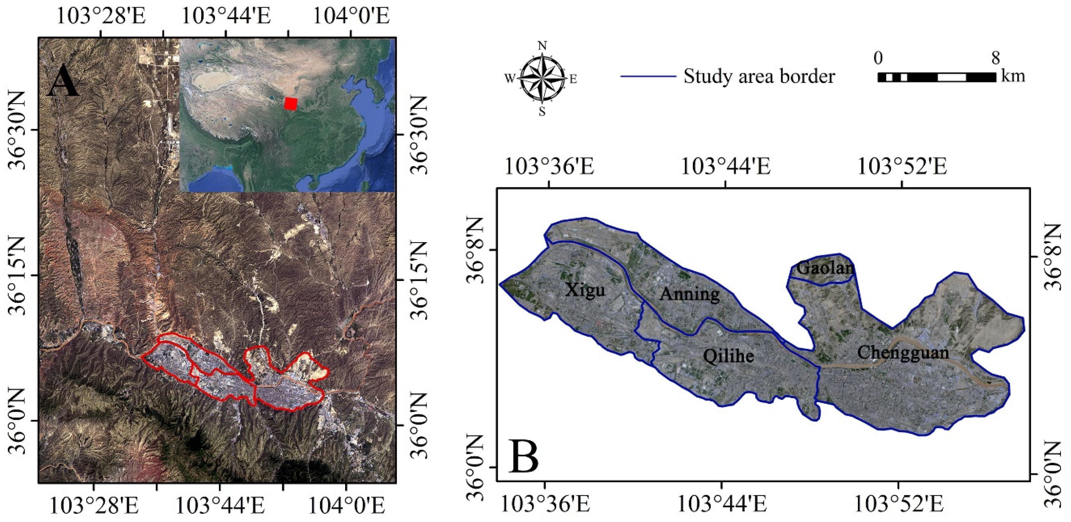
Lanzhou is situated in the western part of China on a loess plateau. The urban area is about 1631.6 km2. The following municipal areas of Lanzhou were investigated in this study: Chengguan District, Qilihe District, Xigu District, Anning District and the land-cutting area of Gaolan County. The location of the study area is presented in Figure 2.
The terrain of the area is high in the west and low in the east. The area has a temperate continental climate; the temperature difference is large about 20 ℃. The annual amount of precipitation is low about 300 mm. The Yellow River runs through the main urban area, and the city is situated in the plain of the eroded and accumulated Yellow River valley; thus, it is a typical valley city situated in a mountainous region. Due to its special topography, landform, geology, climate conditions and aggressive human activities, geological disasters occur frequently in Lanzhou, such as landslides, building collapse, ground collapse, etc. Because Lanzhou is located in the loess region, concentrated precipitation may lead to rapid destruction of soil-soaked ground, resulting in significant deformation.

2.2. Data Sources

A total of 75-scene descending orbits obtained from Sentinel-1A TOPS SAR images (C-band) of Lanzhou acquired from 14 March 2015 to 4 May 2019 were selected to estimate the average vertical surface subsidence velocity and subsidence time-series (https://search.asf.alaska.edu/#/). The Sentinel 1A data are shown in Table 1. Shuttle Radar Topography Mission (SRTM) with 90 m resolution provided by the National Aeronautics and Space Administration (NASA) was used to correct the topography-related phase and geocode interferograms. SBAS-InSAR was used to process the 75-scene descending Sentinel 1A images (Table 1) [12]. PS-InSAR was used to process 32-scene descending Sentinel 1A images covering the study area from March 2015 to January 2017 to perform a cross-validation of the differences between the SBAS-InSAR and PS-InSAR results [13,15]. In our experiment, these were both incorporated into the ENVI 5.5 platform through the SARscape 5.5 module. Most of the time baselines of the data were within one month, and all the spatial baselines of the image pairs complied with the requirements.
Geological data were purchased from the Geo-cloud of China Geological Survey (http://geocloud.cgs.gov.cn/#/portal/home), which includes the location of geological faults and the types of geology found the region. The land cover types were downloaded from Tsinghua University’s global 10 m resolution land cover maps [19].

2.3. Methods and Processing

2.3.1. SBAS-InSAR Algorithm

The SBAS-InSAR was proposed by Berardino [12] and Lanari et al. [20]. SBAS-InSAR time-series analysis method combines the data, and it can be used to obtain the short space baseline differential interferogram dataset. These differential interferograms can overcome spatial decorrelation phenomena. Using Singular Value Decomposition (SVD) to solve the deformation rate, isolated SAR datasets separated by large spatial baselines can be connected to improve the time sampling rate of the observed data. Its high-density temporal and spatial information can effectively eliminate the atmospheric effect phase, resulting in more accurate measurements [16]. The detailed principles are as follows:
(1) N+1 SAR images covering the study area are arranged by followed the time series t 0 to t N , then one of them is select as the super master image, and other slave SAR images are co-registered to this super master image. M multi-visual differential interferograms are generated based on N+1 SAR images. M satisfies the following inequality:
N + 1 2 M N ( N + 1 2 )
(2) The j t h differential interferogram is generated from the slave SAR image obtained at the time of t A and the master SAR image obtained at the time of t B (tB > tA). The interference phase in a pixel of azimuth and range coordinates (x,r) can be expressed as:
δ ϕ j ( x , r ) = ϕ B ( x , r ) ϕ A ( x , r ) 4 π λ [ d ( t B , x , r ) d ( t B , x , r ) ] + Δ ϕ t o p o j ( x , r ) + Δ ϕ a t m j ( t B , t A , x , r ) + Δ ϕ n o i s e j ( x , r )
where j (1, …, M); λ is the central wavelength of the signal; d ( t B , x , r ) and d ( t B , x , r ) are the cumulative shape of the radar line of sight for d ( t 0 , x , r ) = 0 at the time of t B and t A , respectively; Δ ϕ t o p o j ( x , r ) is residual topographic phase in differential interferograms. Δ ϕ a t m j ( t B , t A , x , r ) is atmospheric delayed phase; Δ ϕ n o i s e j ( x , r ) is coherent noise such as system thermal noise.
(3) To obtain the sedimentation sequence with physical significance, the phase in the Formula (2) is expressed as the product of the average phase velocity and time between two obtained times:
v j = ϕ j ϕ j 1 t j t j 1
the j t h phase value of the interferogram can be expressed as:
k = t A , j + 1 t B , j ( t k t k 1 ) v k = δ ϕ j
That is, the velocity of each period needs to be integrated over the time interval between the master and slave images. The form of matrix is:
B v = δ ϕ
Formula (5) is a matrix of M × N. Because the differential interferograms with small baseline sets adopt the multi-principal image strategy, matrix B is prone to rank defect. Using the SVD method, the generalized inverse matrix of matrix B can be achieved, and then the minimum norm solution of the velocity vector can be obtained. Finally, shape variables of each time period can be obtained by integrating the velocities in each time period.
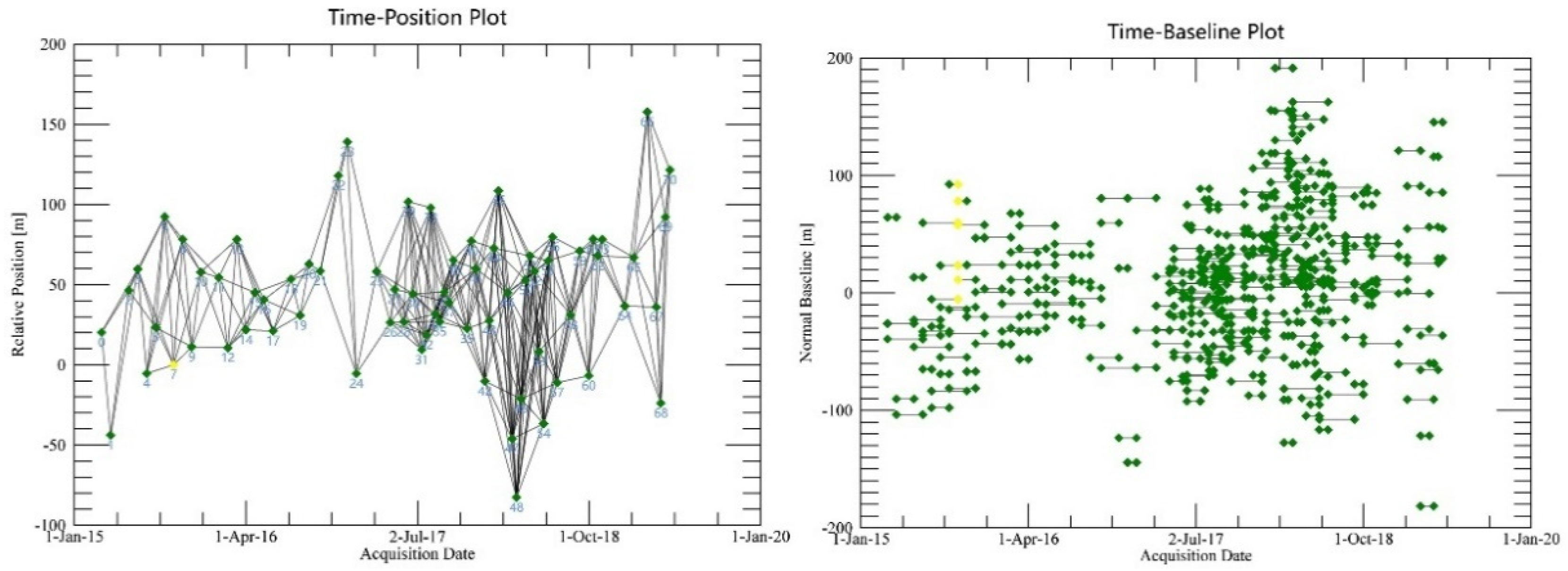
This study used the 75-scene Sentinel-1A SLC images covering the study area from March 2015 to May 2019. The 22 September 2015 image was automatically selected as the super master image, and other slave SAR images were co-registered and resembled to the master image; its maximum time baseline is 200 days, its range lookup is 4 and its azimuth looks is 1. Meanwhile, interferometer pairs with low coherence were removed. Finally, the connection graph was obtained (Figure 3). The interference process mainly includes interferogram generation, de-flattening, filtering, coherent graph generation and phase unwinding. SRTM DEM (Digital Elevation Model) was utilized to remove the terrain phase and registration. The Goldstein filtering method was utilized to remove noise. The polynomial refinement method was used to flatten the image. The Minimum Cost Flow (MCF) method was used only for phase unwrapping of the wrapped figure. Linear model with better robustness was used to estimate the deformation rate and to remove the atmospheric phase to obtain the final deformation rate. Ultimately, the deformation rate of the Line-of-Sight (LOS) converts to the vertical direction.

2.3.2. PS-InSAR Algorithm

The D-InSAR algorithm establishes an interference phase model based on multiple SAR image sequences covering the same area by selecting PS points, and settlement results are achieved by interpreting the model [21]. PS-InSAR was proposed by Ferretti [10]; The PS-InSAR method utilizes a time-series of radar images to identify highly coherent points, the so-called persistent scatterers (PS) [10]. It uses phase stable points to extract deformation information. Because of its coherence, it is rarely affected by time and space baselines; thus, it is possible to prevent the limitation of time and space incoherence of traditional D-InSAR technology [22]. Basically, by using the same area of the SAR images, PS-InSAR uses space borne radar to detect the stability of the point target. Because PS-InSAR technology relies on the point target to analyze the change in the time-series, the point target in the time-series is nearly unaffected by the speckle noise in the SAR image. Moreover, after a long period of time, very high coherence and scattering properties remain stable. In the present study, the temporal and spatial changes of these stable points were analyzed, and the phase composition of each point, including the elevation error, deformation phase and errors caused by atmospheric disturbance, was decomposed. Finally, through iterative regression analysis of the interference phase of these stable points, the time-series variables were calculated, and the accumulation of ground settlement was obtained [23].
PS-InSAR technology is mainly concerned with the discrete spatial distribution of PS points. The i-th image in the time series data sets containing N single look complex (SLC) SAR images was marked as si (i = 1, 2, …, N). Interference pairs composed of the i and k SAR images can be recorded as I i , k = s i s k * . Here, * stands for the complex conjugate operation. Assuming that the target p0 is the reference point, the interferometer phase Δ p , i , k = I p , p 0 i , k will be dependent on the elevation, deformation, atmospheric disturbance and noise difference between the target p and the reference point p0. The phase difference caused by the elevation and line difference between the two targets can be expressed as:
Δ ϕ H , p , p 0 i , k = 4 π λ 1 R sin θ Δ h p , p 0 B n i , k
Δ D , p , p 0 i , k = 4 π λ Δ v p , p 0 B t i , k
In the formulae, Δ h p , p 0 and Δ v p , p 0 is the difference of elevation and deformation rate between target p and p 0 . B n i , k and B t i , k represent the spatial baseline and time baseline perpendicular to the radar line of sight between SAR images i and k, respectively. λ is the radar signal wavelength, R is the oblique distance between the target and the satellite, and θ is the incident angle of SAR.
The target elevation and its subsidence rate were usually estimated by maximizing time coherence:
Δ 1 h p , Δ 1 v p = arg { max ( | ξ p | ) }
ξ p = 1 M i , k e j ( Δ ϕ p i , k Δ ϕ H , p i , k Δ ϕ D , p i , k )
where, M is the number of interferograms. Δ ϕ p i , k are the differential interferometer phase. Δ ϕ H , p i , k is the elevation correlation partial phase, and Δ ϕ D , p i , k is the terrain deformation correlation phase.
The land deformation Δ ϕ D , p i , k is mainly composed of linear deformation phase and nonlinear deformation phase.
ϕ D , p i , k = ϕ l i n e a r i , k + ϕ n o n l i n e a r i , k = 4 π λ ( Δ v p B t i , k + D e f o n o n l i n e a r )
where, ϕ n o n l i n e a r i , k is a nonlinear variable. In Formula (9), the maximization factor ξ = max ( | ξ p | ) was called time coherence and the time coherence of the target can be approximately expressed as 1 ξ p e δ 2 / 2 a function of the deviation of the phase residual. Finally, the variance of elevation and deformation rate is calculated by PS-InSAR technology.
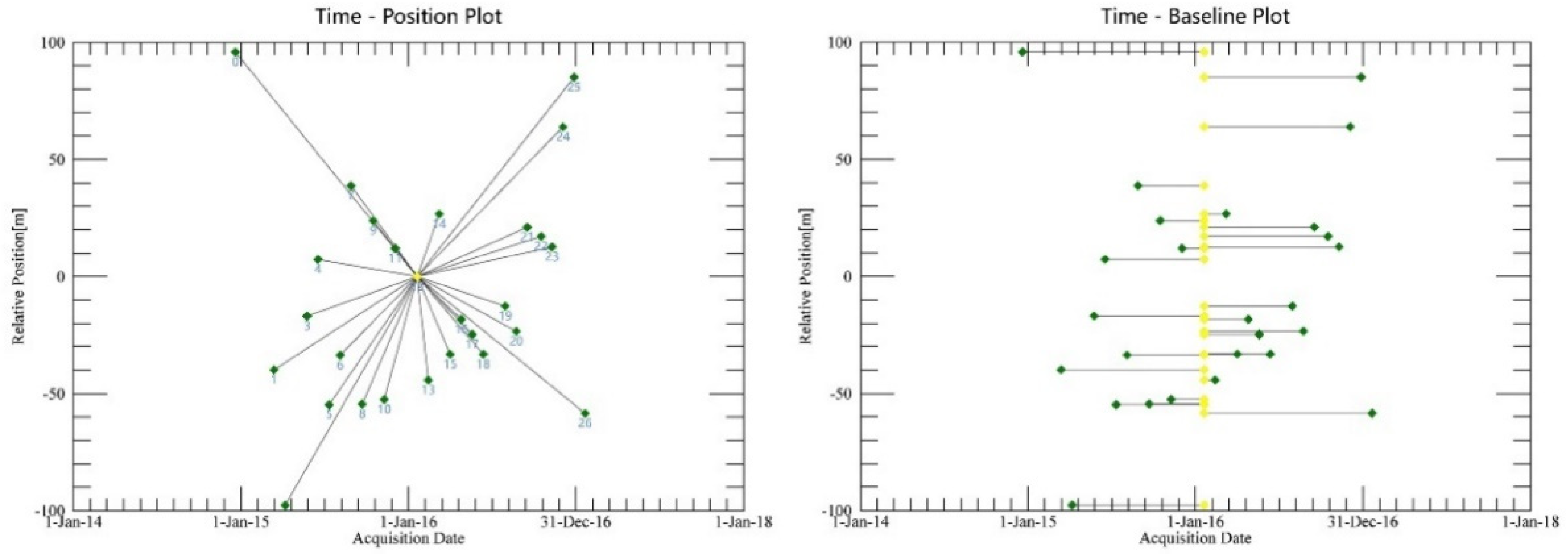
This study also used 32-scene Sentinel-1A SLC images covering the investigated area from March 2015 to January 2017. Firstly, a super master image was automatically selected by the program, the 20 January 2016 image was selected as the super master image, and other slave SAR images were co-registered and resembled to the master image, the coordinate system was converted to the master image coordinate system. Secondly, the connection graph was generated (Figure 4) and the interference was carried out. The interferometer process mainly includes interferogram generation, PS points selection, de-flattening, filtering, phase unwrapping, geometric ground control points (GCPs) selection, atmospheric phase removal, and PS points estimation and geocoding. DEM was applied to flatten the terrain phase. If there was an error in the geographical position of the DEM, GCPs were needed to correct the SAR images and DEM. The coherence threshold was 0.85 to improve the coherence in interferometer procedure. Then, the number of GCPS selected in no deformation areas was 40 to remove the phase of atmosphere and noise. Meanwhile, the interferometer pairs with low coherence were removed. The Goldstein filtering method was used to remove noise. The polynomial refinement method was used to flatten the image and eliminate the orbital phase. The three dimensions (3D) method was used for phase unwrapping of the wrapped figure. Finally, we could achieve the time series of PS points. Ultimately, the deformation rate of the line-of-sight (LOS) converts to the vertical direction.

2.3.3. Mann–Kendall Test

The Mann–Kendall (M–K) test is a non-parametric statistical method that was proposed and developed by Mann and Kendall [24]. Its advantages are that it does not require the samples to follow a specific distribution, and it is not impacted by a small number of outliers. It is more suitable for type variables and order variables. The advantage of this method is that the calculation is simple, and the start time of the mutation can be specified. This mutation monitoring method is widely used [25]. The method is as follows:
The time series is random and independent, the defined statistics are expressed as:
U F k = s k E ( s k ) V a r ( S k ) ,   ( k = 1 , 2 , , n )
Where, UFk is the standard normal distribution, and the sequence of statistics is calculated by the order of time series x1, x2, …, xn. sk is the cumulative number, E ( s k ) is the mean value, and V a r ( S k ) is the variance.
If you follow the time series x in reverse order xn, xn-1, … x1, the above process was repeated to calculate UBk. UFk and UBk curves are drawn, respectively. If the UFk and UBk curves intersect at a point between the borderline, then the moment at which they intersect is the abrupt point.

3. Results and Analysis

3.1. Validation of the Results

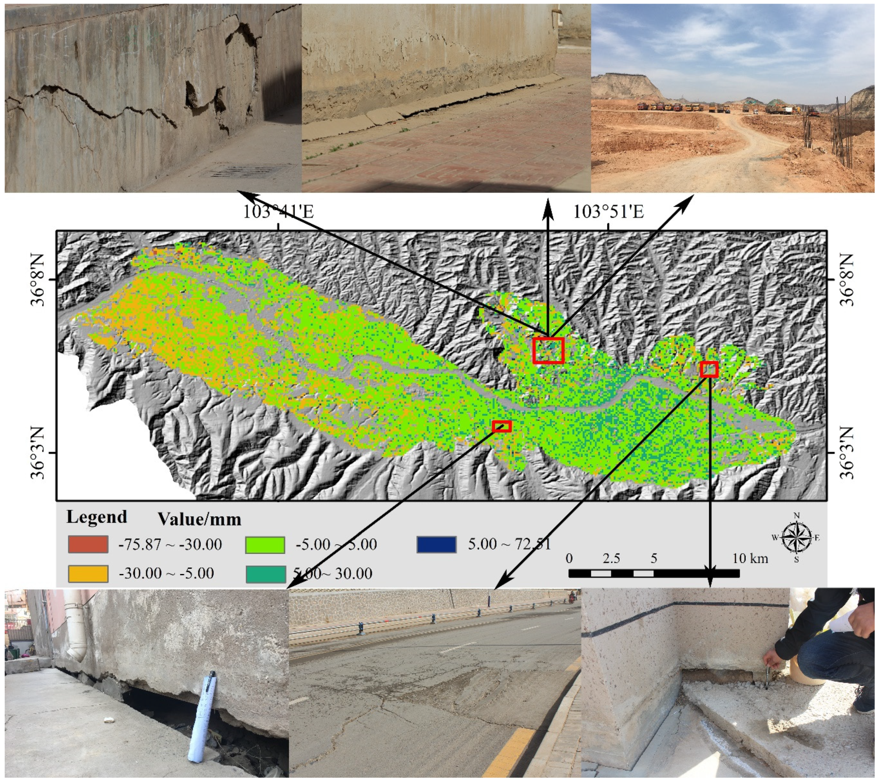
To quantitatively determine the accuracy of the land surface deformation, a cross-validation of the differences between the PS-InSAR and SBAS-InSAR results were used. The two sets of SAR data had overlapped part of the time series from March 2015 to January 2017, thus the differences during the overlapped timing sequence were used to test these two result sets. The Raster Calculator was utilized to calculate the differences in the PS-InSAR and SBAS-InSAR results (Figure 5).
To quantitatively analyze the differences between the PS-InSAR and SBAS-InSAR results, we counted the number of distribution and determined the cumulative percentage (Table 2). The verification results were mainly distributed from −5 mm to 5 mm, which accounted for a cumulative percentage of 88.83%. The average value of the differences between the PS-InSAR and SBAS-InSAR results covering the study area was 0.14 mm, the maximum and minimum values were 72.51 mm and −75.87 mm, respectively. It was found that most of the validation results in the study area were less than 10 mm, indicating that the two sets of data were well tested, and ground deformation rate calculations were reliable. However, the recorded differences between SBAS-InSAR and PS-InSAR results may be explained by errors from the two algorithms. The PS density is usually low in vegetated, forested and low-reflectivity areas [26], while the SBAS performs better in nonurban vegetated areas, and also in areas with high deformation rates [4]. Furthermore, the research team went to the field to investigate surface deformation in Lanzhou (Figure 5). Country Garden and Jiuzhou were more severely deformed, and the types of deformation mainly were cracks, subsidence and ground collapses. Surface deformation locations were consistent with the InSAR results.

3.2. Spatial Distribution of the Surface Deformation

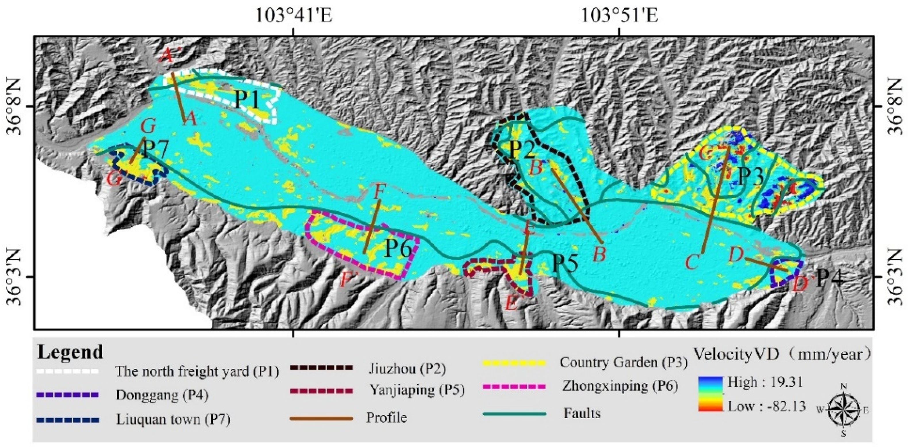
InSAR is more sensitive to vertical than horizontal movements. We convert LOS (dLOS) into vertical displacement (dv) for every time-series using the Sentinel-1A incidence angle (θ = 39.58°): dv = dLOS/cosθ. In the rest of this paper we use vertical deformation rates converted from the observed LOS rates. The mean deformation rate map was generated using the SBAS-InSAR and Sentinel 1-A images (Figure 6). The land surface deformation rate of Lanzhou ranges from −82.13 mm/year to 19.31 mm/year. Surface deformation rates of most areas (87.23%) range from −10 mm/year to 10 mm/year, which indicates that the land surface is stable in this city. However, some serious surface deformation locations were detected in the following regions: the north freight yard (P1), Jiuzhou (P2), Country Garden (P3), Donggang (P4), Yanjiaping (P5), Zhongxinping (P6) and Liuquan (P7) (Figure 6). Among these seven regions, P3 was identified as having the largest deformation, and its surface deformation range was also the largest. A more detailed surface deformation analysis and explanation for regions P1−P7 will be presented in Section 4.

3.3. Time-Series Land Surface Deformation Map

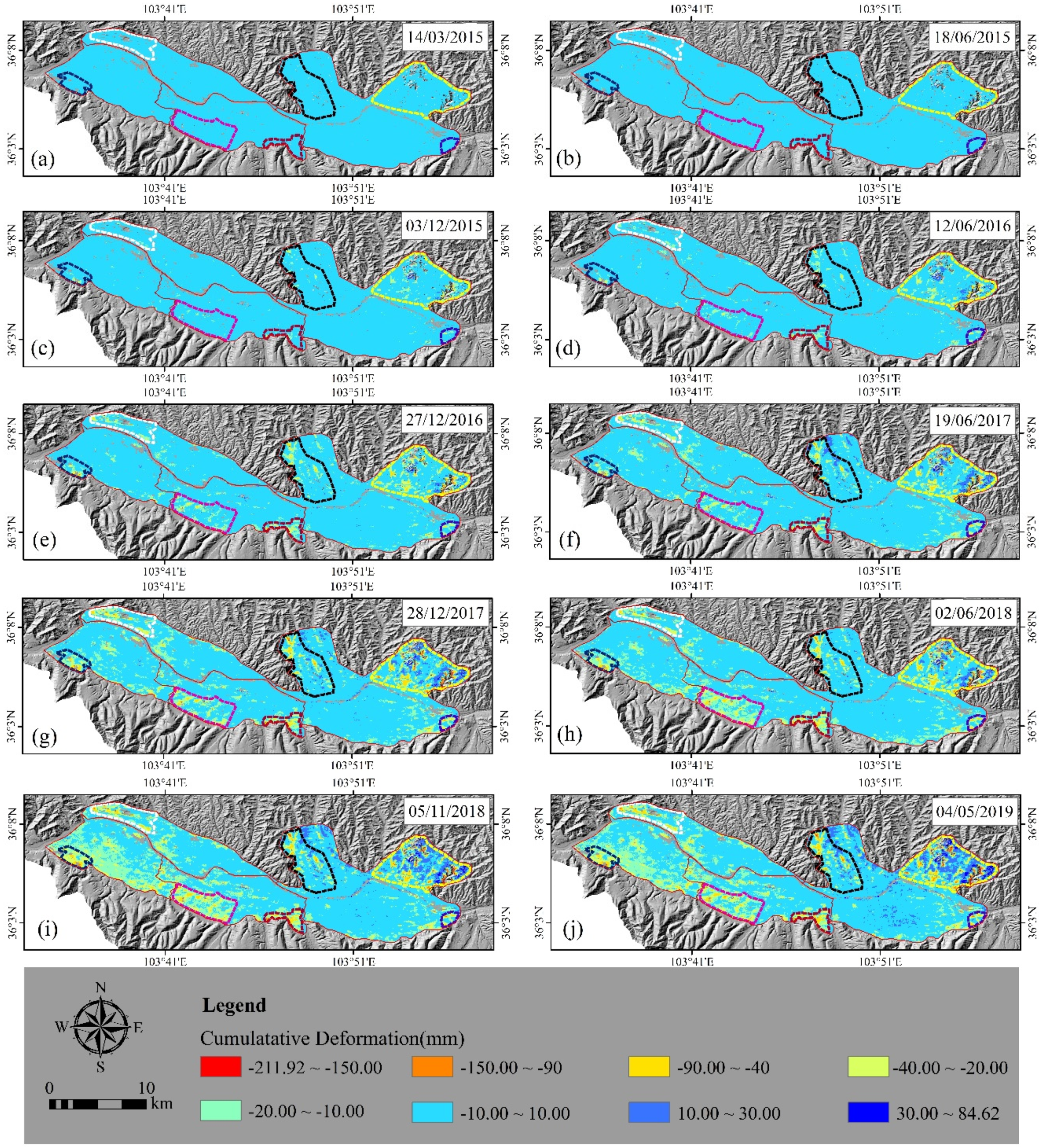
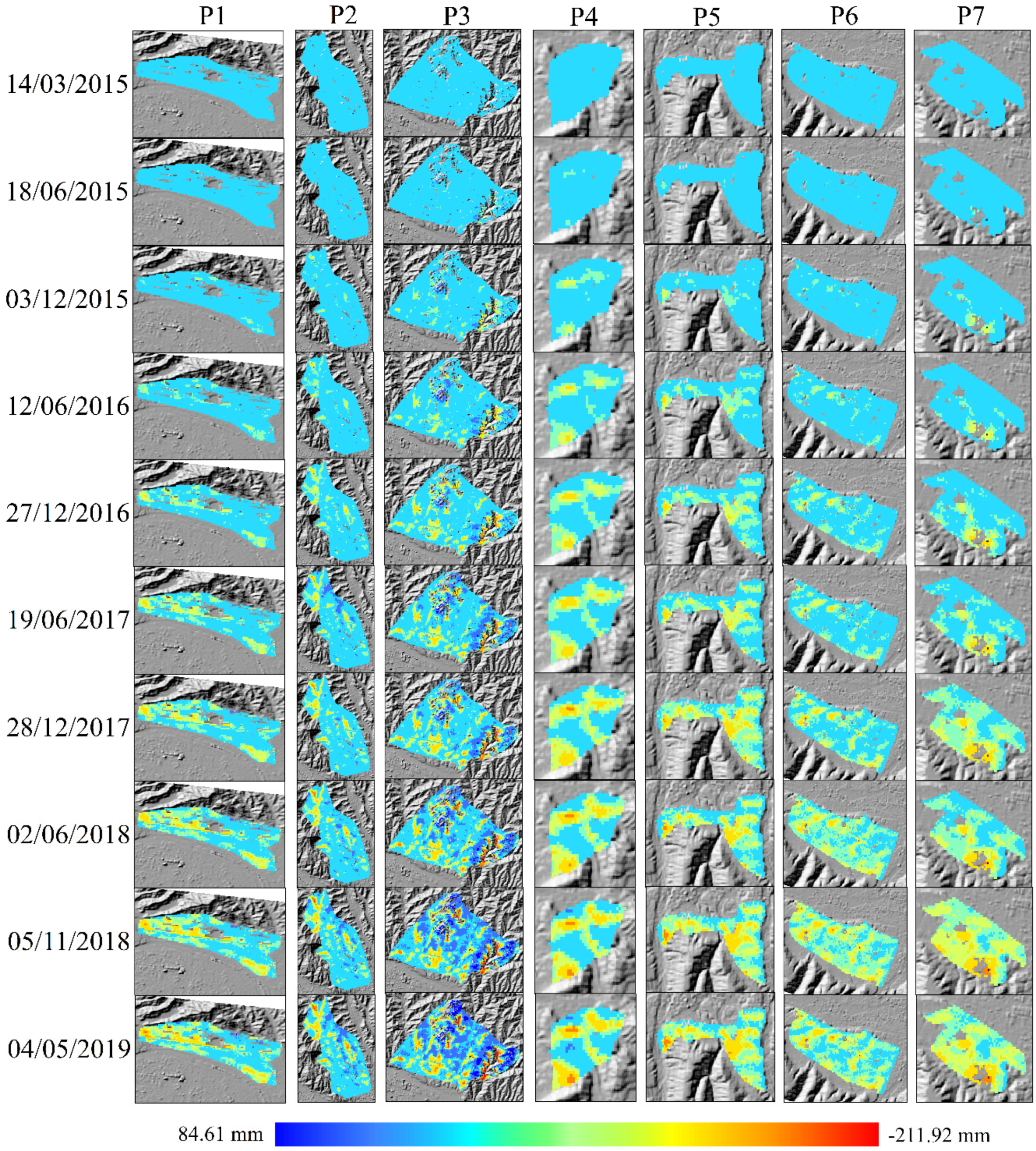
The 10 images have been selected among 75 images at intervals of about six months to show the time-series land surface deformation and reduce the number of images presented in Figure 7. At the beginning of March 2015, there were no deformations in Lanzhou; however, in December 2015 surface deformation increased over time in the major deformation regions, including Country Garden (P3), Jiuzhou (P2), Liuquan (P7) and Yanjiaping (P5). In December 2016, surface deformation was aggravated in Country Garden (P3), Jiuzhou (P2), the north freight yard (P1), Liuquan (P7), Yanjiaping (P5), Zhongxinping (P6) and Donggang (P4). In December 2017, the deformation and deformation range of the Xigu District increased rapidly. Six months later, this trend was holding back and it was gradually eliminated. In May 2019, the ultimate deformation was formed and distributed in the regions under study. More details on the distribution of the surface deformation for Regions P1−P7 are shown in Figure 8.

3.4. Mutation Analysis of Surface Deformation for Regions P1−P7

Statistics of UF and UB were calculated, and the UF and UB curves were plotted. M-K mutation test results (Figure 9) show that mutations of deformation occurred in P1 and P2 in July 2017 and September 2017, respectively, while the mutations of deformation occurred in P3 in September 2018. They occurred in P4 in May 2017, and in P5, P6 and P7 in June 2017. The significance level for all these regions was P > 0.05, indicating that surface deformation expansion was significant after June 2017, and it continued to expand. Surface deformation M–K test results are in good agreement with the time-series analysis results for Regions P1−P7 (Figure 8).

4. Discussion

The reasons for land surface deformation are complex due to the complex geological environment in Lanzhou and human activities (land cover/land cover changes) in that city. We explored how geology, geological faults, land cover types and land cover changes caused the observed land surface deformation in the region.

4.1. Relationship between Land Surface Deformation and Geology

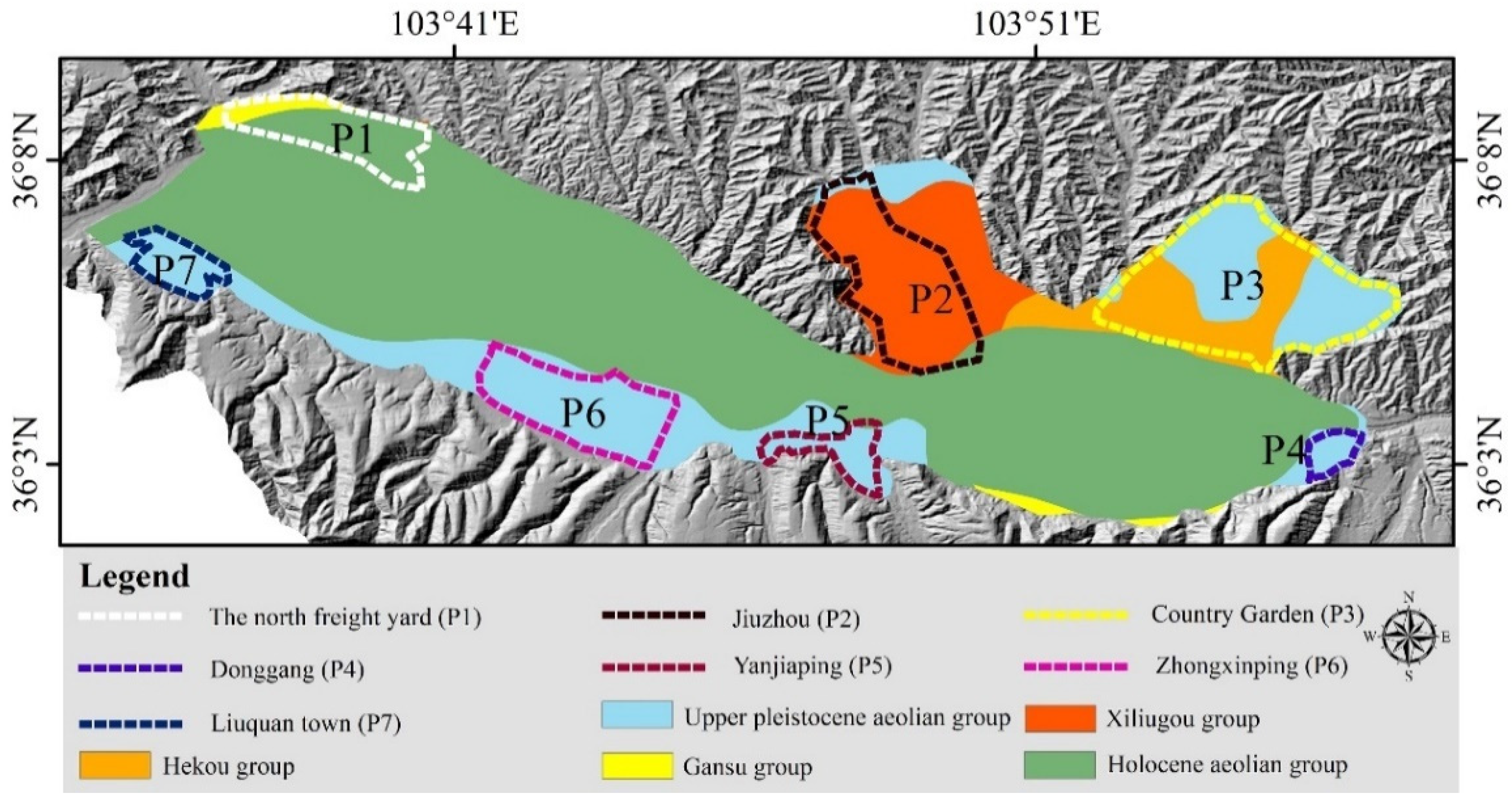
The geological data of the studied area showed five main types of geology (Figure 10):
1. The Upper Pleistocene Aeolian Group, which mainly consists of loess.
2. The Xiliugou Group, which mainly consists of red massive loose sandstone, grey-white fine conglomerate and glutenite.
3. The Hekou Group, which mainly consists of sandstone, conglomerate, glutenite, argillaceous siltstone and mudstone.
4. The Gansu Group, which consists of mudstone, sandy mudstone and glutenite mixed with marlstone.
5. The Holocene Aeolian Group, which mainly consists of sub-sand soil, a sub-clay sand layer and a gritty layer lens body.
Bozzano et al. [27] indicated that local geological conditions control the magnitude of the deformation process. In this section, we discuss the relationship between land surface deformation and geology in regions P1−P7.
In Region P1, the geology is part of the Holocene Aeolian Group and the Gansu group, which consist of materials, such as sub-sand soil, a sub-clay sand layer, a gritty layer lens body, mudstone, sandy mudstone and glutenite mixed with marlstone. The gravel layer is dominated by medium gravel, with moderate weathering and good roundness [28]. The gravel layer has high shear strength, fast compaction under external load, little deformation and high bearing capacity [29]. The shear strength of the mudstone and sandstone is linked to their lithology and water content. Rock masses with large water content are weak, and they show plastic failure and have low shear strength [30]. The hydrological properties of the materials are mainly swelling and disintegration after encountering water. The repeated changes of the wet and dry cycle will destroy the mudstone [31]. Therefore, Region P1 had serious surface deformation. In Region P2, the geology is mainly part of the Xiliugou Group and the Upper Pleistocene Aeolian Group, which consist of materials, such as red massive loose sandstone, grey-white fine conglomerate, glutenite and loess. Due to the larger natural moisture content, high compressibility, low strength, and poor structure of soft clay, structures built on soft clay subgrade are more prone to displacement and instability [32]. The shear strength of sandstone is linked to its lithology and water content. Rock masses with considerable water content are weak, and they show plastic failure and have low shear strength [30]. It is well-known that loess has collapsibility [33,34]; therefore, surface deformation was seen in Region P2. In Region P3, the geology is part of the Hekou Group and the Upper Pleistocene Aeolian Group, which consist of materials such as sandstone, conglomerate, glutenite, argillaceous siltstone, mudstone and loess. The shear strength of sandstone is related to its lithology and water content. The hydrological properties of sandstone are mainly swelling and disintegration after encountering water, and deformation tends to occur when the water content is brought up. Moreover, the loess is prone to collapse, so these factors will inevitably lead to regional deformation. In P4, P5, P6 and P7, the geology is part of the Upper Pleistocene Aeolian Group, which consists of loess that is prone to collapsing. The main hazard associated with collapsible loess is the damage of the large pore structure of the soil after it comes into contact with water; this results in significant collapsible deformation, causing a building’s foundation to sink [35,36,37]. In summary, the geological characteristics of Lanzhou are important factors that impact surface deformation.

4.2. Surface Deformation in Relation to Geological Faults

To verify the relationship between land surface deformation and geological faults, we drew seven profiles that crossed the fault lines. These profiles are placed in Regions P1−P7 (Figure 11).
We analyzed the surface deformation rate along seven profile lines, denoted as (1) A-A’, (2) B-B’, (3) C-C’,(4) D-D’, (5) E-E’, (6) F-F’ and (7) G-G’ (Figure 12). These lines cross the geological faults.
There are five processes for the A-A’ profile (Figure 12a):
1. The surface deformation rate is approximately −3 mm/year.
2. The surface deformation rate showed a fluctuating trend.
3. The surface deformation rate increased along the profile to about −6 mm/year.
4. The surface deformation rate decreased to about −2 mm/year.
5. The surface deformation rate rapidly increased to the maximum value of −20 mm/year.
Near the end of the profile line, the surface deformation rate showed a fluctuating upward trend before decreasing to be almost stable.
There are four processes for the B-B’ profile (Figure 12b):
1. The surface deformation rate showed a fluctuating trend.
2. The surface deformation rate increased along the profile to about −14 mm/year.
3. The surface deformation rate reduced to about 2 mm/year.
4. The surface deformation rate is increased to the maximum value of −22 mm/year.
There are three processes for the C-C’ profile (Figure 12c):
1. The surface deformation rate showed a fluctuating trend.
2. The surface deformation rate is increased to the maximum value of −30 mm/year.
3. The surface deformation rate decreased to about 5 mm/year.
There were three processes for the D-D’ profile (Figure 12d):
1. The surface deformation rate showed a fluctuating trend.
2. The surface deformation rate increased to the maximum value of −20 mm/year.
3. The surface deformation rate decreased to about −4 mm/year.
For the E-E’ profile (Figure 12e), the surface deformation rate showed a fluctuating increase tendency. For the F-F’ profile, the surface deformation rate showed an increase to about −8 mm/year and decrease to 1 mm/year in the cycle. For the G-G’ profile (Figure 12f), the surface deformation rate showed a fluctuating increase trend. It is obvious that the surface deformation rate of the A-A’, C-C’ and D-D’ profiles is the highest in the geological faults, while the surface deformation rate of the B-B’, E-E’, F-F’ and G-G’ profiles showed the maximum in faults.
The geological activity in the fault layer is actively involved and it can easily slide [38]. The location of faults has a clear effect on the spatial distribution of land subsidence, probably due to the abrupt discontinuity in horizontal hydraulic conductivity related to the structure of the basement and the vertical differential compaction of heterogeneous geological materials [39]. Hence, geological faults make a strong impact on land surface deformation. This also demonstrates that the location of the surface subsidence is closely related to its geological fault in the city of Lanzhou.

4.3. Surface Deformation in Relation to Land Cover/land Cover Changes

The overexploitation of ground water was the major cause of surface deformation [2]. However, due to the difficulty in accessing water extraction bookkeeping records from local water management agencies, we are not in a position to obtain the groundwater level changes. Instead, we utilized land cover types as a proxy for the general amount of groundwater extracted, the percentage of groundwater use in the area is: agricultural (77%), urban (13%) and industry (10%) [4]. We used the world land cover types map released by Tsinghua University, and we combined these with optical images to distinguish land cover types. The seven regions investigated in this study have different degrees of deformation and diverse land cover types.
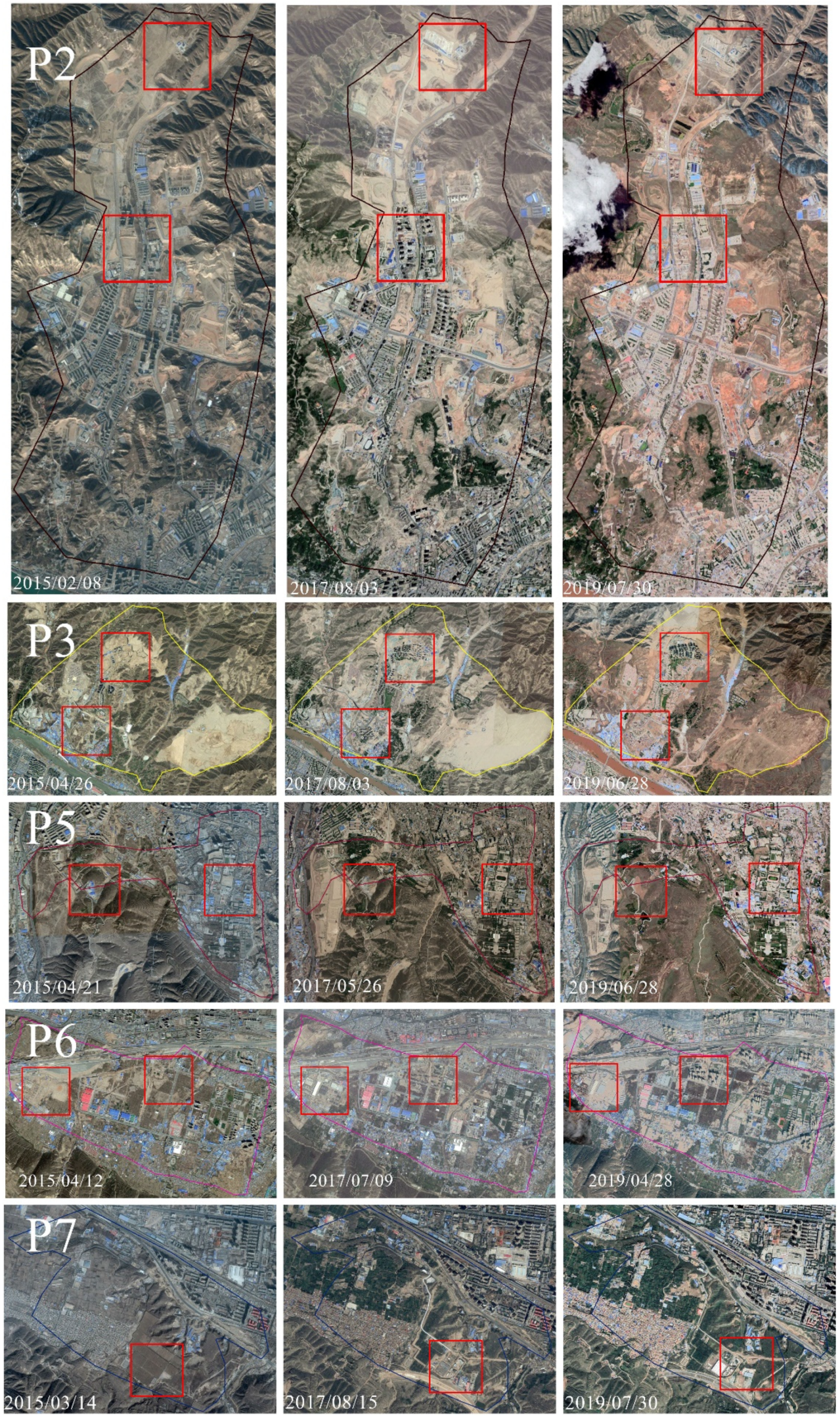
In P1, P2, P3, P5 and P6, the land cover type is urban, which includes residences, infrastructure and a network of underground. As shown in Figure 13, that the type of land cover changed from 2015 to 2019, due to land creation (P2,P3) and construction (P5,P6). We concluded that the time of land cover changed in accordance with the time of mutation of deformation (Figure 9). Land cover change may be one reason for land surface deformation and the reason for mutation [40]. The construction of a large number of projects, including the development of underground space and the excavation of building foundation pits, resulted in the extraction of underground liquid supports, the excavation of solid supports and the destruction of the stress balance between the rock and soil, resulting in the formation of land surface deformation [41]. In P4, the cover is industry, as saw in the area known as the Xinglong Industrial Park that is home to many logistics companies and warehouses. Static load may be the main factor for deformation [42,43]. In P7, the land cover consists of a small number of houses and large stretches of farmland, which belongs to agricultural areas. In this region, new buildings were erected in 2015–2019, and the time of land cover changed in accordance with the time of the mutation (Figure 9, Figure 13). The annual amount of local rainfall is insufficient to support the region’s agricultural production, so underground water needs to be mined, which irrigated large stretches of farmland that require a large amount of water. Rain-fed and agricultural land-use types showed higher subsidence rates, due to rain-fed and irrigation had a high impact of the seasonal water table lowering [44]. To sum up, construction and irrigation may be the reasons for deformation [23,45] in region P7.
The observed surface deformation rates discussed above being summarized in Table 3. The land cover changes are illustrated in Figure 13. The time of the land cover changes are in accordance with the time of the mutation, and notarized land cover changes for land creation and construction may be the cause for the mutation. Regions P1−P7 are limited by geological faults, and there are geological differences on both sides of the fault lines, indicating that land surface deformation is pertinent to geological faults. Therefore, the surface deformation of Lanzhou is related to geology, geological faults and land cover/land cover changes.

5. Conclusions

This study was designed to detect the spatial position of surface deformation in Lanzhou and understand its mechanism using a total of 75-scene descending orbits obtained from Sentinel-1A TOPS SAR (C-band) model image data. The data were acquired in descending orbits between March 2015 and May 2019 and processed using SBAS-InSAR. Cross-validation among the PS-InSAR, SBAS-InSAR results and field investigation was performed. The relationship between surface deformation and geology, geological faults and land cover types in the city of Lanzhou was analysed in detail. The main conclusions are as follows: The results obtained by SBAS-InSAR, PS-InSAR and investigation in field work showed good agreement. The results were cross-validated to ensure the accuracy. The land surface deformation rate of Lanzhou ranges from −82.13 mm/year to 19.31 mm/year, and most of the areas are stable. However, some serious surface deformation locations were detected in the following regions: the north freight yard, Jiuzhou, Country Garden, Donggang, Yanjiaping, Zhongxinping and Liuquan. Time-series land surface deformation analysis showed that deformation increased over time in the major deformation regions. Surface deformation expansion was significant after June 2017 and the surface deformation continued to expand. Surface deformation in Lanzhou is affected by geology, geological faults and land cover/land use changes, geological structure affects the surface deformation, in that the surface deformation changes obviously across the faults. And spatial distribution of deformation is highly related to land creation and construction, industrial areas and agricultural areas. Future studies will need to go to quantitative methods to further analyze the mechanisms of surface deformation in Lanzhou city, such as the relationship between surface deformation and groundwater, the periodic characteristics of signals using more data.

Author Contributions

Y.H. conceived the idea, designed the experiments, contributed to translate and modify the paper, and drafted the manuscript; W.W. performed the experiments, produced the results; H.Y. audited the figures; L.Z. downloaded the data; Y.C. finished methods; S.Y. helped to modify the paper. All authors have read and agreed to the published version of the manuscript.

Funding

This work is funded by the National Key R&D Program of China (2017YFB0504201), Tianyou Youth Talent Lift Program of Lanzhou Jiaotong University, the Youth fund of LZJTU (No. 2017002), LZJTU EP 201806, the natural science foundation of Gansu province (17JR5RA095), the National Scientific Foundation of China (Grants Nos. 41371435, 41,761,088 41761014, 41,761,082 and 41861059) and the National Key Research and Development Program of China (2016YFC0803106), “InSAR monitoring of land subsidence in main urban area of Lanzhou city” by department of education of Gansu Province (2019A-043), China postdoctoral science foundation (2019M660092XB).

Acknowledgments

Thanks for Alaska Satellite Facility: making remote-sensing data accessible for providing Sentinel1-A images and ASTER GDEM. The authors thank the anonymous reviewers and editors for their constructive comments and suggestions.

Conflicts of Interest

No potential conflict of interest was reported by the authors.

References

  1. Galloway, D.L.; Burbey, T.J. Regional land subsidence accompanying groundwater extraction. Hydrogeol. J. 2011, 19, 1459–1486. [Google Scholar] [CrossRef]
  2. Zhu, L.; Gong, H.; Li, X.; Wang, R.; Chen, B.; Dai, Z.; Teatini, P. Land subsidence due to groundwater withdrawal in the northern Beijing plain, China. Eng. Geol. 2015, 193, 243–255. [Google Scholar] [CrossRef]
  3. Ng, A.H.-M.; Ge, L.; Li, X.; Zhang, K. Monitoring ground deformation in Beijing, China with persistent scatterer SAR interferometry. J. Geod. 2012, 86, 375–392. [Google Scholar] [CrossRef]
  4. Chaussard, E.; Wdowinski, S.; Cabral-Cano, E.; Amelung, F. Land subsidence in central Mexico detected by ALOS InSAR time-series. Remote Sens. Environ. 2014, 140, 94–106. [Google Scholar] [CrossRef]
  5. Du, Z.; Ge, L.; Ng, A.H.-M.; Xiaojing, L.; Li, L. Mapping land subsidence over the eastern Beijing city using satellite radar interferometry. Int. J. Digit. Earth 2018, 11, 504–519. [Google Scholar] [CrossRef]
  6. Cui, Z.-D.; Yang, J.-Q.; Yuan, L. Land subsidence caused by the interaction of high-rise buildings in soft soil areas. Nat. Hazards 2015, 79, 1199–1217. [Google Scholar] [CrossRef]
  7. Du, Z.Y.; Ge, L.L.; Ng, A.H.-M.; Zhu, Q.G.; Yang, X.H.; Li, L.Y. Correlating the subsidence pattern and land use in Bandung, Indonesia with both Sentinel-1/2 and ALOS-2 satellite images. Int. J. Appl. Earth Obs. Geoinf. 2018, 67, 54–68. [Google Scholar] [CrossRef]
  8. Imamoglu, M.; Kahraman, F.; Cakir, Z.; Sanli, F.B. Ground Deformation Analysis of Bolvadin (W. Turkey) by Means of Multi-Temporal InSAR Techniques and Sentinel-1 Data. Remote Sens. 2019, 11, 1069. [Google Scholar] [CrossRef] [Green Version]
  9. Dehghan-Soraki, Y.; Sharifikia, M.; Sahebi, M.R. A comprehensive interferometric process for monitoring land deformation using ASAR and PALSAR satellite interferometric data. Gisci. Remote Sens. 2015, 52, 58–77. [Google Scholar] [CrossRef]
  10. Ferretti, A.; Prati, C.; Rocca, F. Permanent scatterers in SAR interferometry. IEEE Trans. Geosci. Remote Sens. 2001, 39, 8–20. [Google Scholar] [CrossRef]
  11. Cigna, F.; Osmanoğlu, B.; Cabral-Cano, E.; Dixon, T.H.; Ávila-Olivera, J.A.; Garduño-Monroy, V.H.; DeMets, C.; Wdowinski, S. Monitoring land subsidence and its induced geological hazard with Synthetic Aperture Radar Interferometry: A case study in Morelia, Mexico. Remote Sens. Environ. 2012, 117, 146–161. [Google Scholar] [CrossRef]
  12. Berardino, P.; Fornaro, G.; Lanari, R.; Sansosti, E. A New Algorithm for Surface Deformation Monitoring Based on Small Baseline Differential SAR interferograms. IEEE Trans. Geosci. Remote Sens. 2002, 40, 2375–2383. [Google Scholar] [CrossRef] [Green Version]
  13. Hooper, A. A multi-temporal InSAR method incorporating both persistent scatterer and small baseline approaches. Geophys. Res. Lett. 2008, 35. [Google Scholar] [CrossRef] [Green Version]
  14. Ferretti, A.; Fumagalli, A.; Novali, F.; Prati, C.; Rocca, F.; Rucci, A. A new algorithm for processing interferometric data-stacks: SqueeSAR. IEEE Trans. Geosci. Remote Sens. 2011, 49, 3460–3470. [Google Scholar] [CrossRef]
  15. Chen, G.; Zhang, Y.; Zeng, R.; Yang, Z.; Chen, X.; Zhao, F.; Meng, X. Detection of land subsidence associated with land creation and rapid urbanization in the chinese loess plateau using time series insar: A case study of Lanzhou new district. Remote Sens. 2018, 10, 270. [Google Scholar] [CrossRef] [Green Version]
  16. Liao, M.S.; Wang, T. Time Series InSAR Technology and Application; Science Press: Beijing, China, 2014; pp. 77–88. [Google Scholar]
  17. Shi, M.J. Study on Land Use and Its Landscape Ecological Change in Lanzhou Main Urban Area during 1961–2015. Ph.D. Thesis, Lanzhou University, Lanzhou, China, 2016. [Google Scholar]
  18. Guralnik, O.G. Accelerate research on land creation. Nature 2014, 510, 29–31. [Google Scholar]
  19. Gong, P.; Liu, H.; Zhang, M.; Li, C.; Wang, J.; Huang, H.; Clinton, N.; Ji, L.; Li, W.; Bai, Y.; et al. Stable classification with limited sample: Transferring a 30-m resolution sample set collected in 2015 to mapping 10-m resolution global land cover in 2017. Sci. Bull. 2019, 64, 370–373. [Google Scholar] [CrossRef] [Green Version]
  20. Lanari, R.; Mora, O.; Manunta, M.; Mallorquí, J.J.; Berardino, P.; Sansosti, E. A small-baseline approach for investigating deformations on full-resolution differential SAR interferograms. IEEE Trans. Geosci. Remote Sens. 2004, 42, 1377–1386. [Google Scholar] [CrossRef]
  21. Liu, G.; Jia, H.; Zhang, R.; Zhang, H.; Sang, M. Exploration of subsidence estimation by persistent scatterer insar on time series of high resolution terrasar-x images. IEEE J. Sel. Top. Appl. Earth Obs. Remote Sens. 2011, 4, 159–170. [Google Scholar] [CrossRef]
  22. Ding, R.R.; Xu, J.; Lin, X.B. Monitoring of surface subsidence using PSInSAR with TerraSAR–X high resolution data. Remote Sens. Land Resour. 2015, 27, 158–164. [Google Scholar]
  23. Li, G.Y.; Zhang, R.; Liu, G.X.; Yu, B.; Zhang, B. Land subsidence detection and analysis over Beijing-Tianjin-Hebei area based on Sentinel-1A TS-DInSAR. J. Remote Sens. 2018, 22, 633–646. [Google Scholar]
  24. Wei, F.Y. Modern Techniques of Climate Statistical Diagnosis and Prediction; China Meteorological Press: Beijing, China, 1999. [Google Scholar]
  25. Ran, D.; Yao, W.; Jiao, P. Identification and comprehensive diagnosis of sharp change of annual runoff volume and silt discharge series at Toudaoguai Hydrometric station in the upper reaches of the Yellow River. Arid Zone Res. 2014, 31, 928–936. [Google Scholar]
  26. Crosetto, M.; Monserrat, O.; Cuevas-González, M.; Devanthéry, N.; Crippa, B. Persistent Scatterer Interferometry: A review. ISPRS J. Photogramm. Remote Sens. 2016, 115, 78–89. [Google Scholar] [CrossRef] [Green Version]
  27. Bozzano, F.; Esposito, C.; Franchi, S.; Mazzanti, P.; Perissin, D.; Rocca, A.; Romano, E. Understanding the subsidence process of a quaternary plain by combining geological and hydrogeological modelling with satellite InSAR data: The Acque Albule Plain case study. Remote Sens. Environ. 2015, 168, 219–238. [Google Scholar] [CrossRef]
  28. Zhang, M.M. Gravel Fabric characteristics and Environment significance of Terrace Gravel Layers of the Yellow River in North Mountain, Lanzhou Basin. Master’s Thesis, Northwest Normal University, Lanzhou, China, 2018. [Google Scholar]
  29. Shi, H.R.; Zhao, Q.S.; Zhao, G.J. Engineering Geological Characteristics of Sandy Gravel and Leakage Prevention of Dam Foundation in Zhejiang Province. J. Zhejiang Univ. Water Resour. Electr. Power 2000, 4, 12–15. [Google Scholar]
  30. Ning, P.L.; Wang, H.L. Characteristics of tertiary red bed mudstone and sandstone in huicheng basin. Highway 2019, 12, 252–254. [Google Scholar]
  31. Sun, C.; Li, G.; Zhang, S.; Xu, J.; Yang, H. Mechanical and Heterogeneous Properties of Coal and Rock Quantified and Mapped at the Microscale. Appl. Sci. 2020, 10, 342. [Google Scholar] [CrossRef] [Green Version]
  32. Xing, X.; Chen, L.; Yuan, Z.; Shi, Z. An Improved Time-Series Model Considering Rheological Parameters for Surface Deformation Monitoring of Soft Clay Subgrade. Sensors 2019, 19, 3073. [Google Scholar] [CrossRef] [Green Version]
  33. Yuan, Z.X.; Wang, L.M. Collapsibility and seismic settlement of loess. Eng. Geol. 2009, 105, 119–123. [Google Scholar] [CrossRef]
  34. Wu, Q.; Jia, C.; Chen, S.; Li, H. SBAS-InSAR Based Deformation Detection of Urban Land, Created from Mega-Scale Mountain Excavating and Valley Filling in the Loess Plateau: The Case Study of Yan’an City. Remote Sens. 2019, 11, 1673. [Google Scholar] [CrossRef] [Green Version]
  35. Xu, Z.P. Settlement analysis and treatment of collapsible loess foundation in a project. Shanxi Archit. 2019, 45, 76–77. [Google Scholar]
  36. Derbyshire, E.; Meng, X.; Wang, J.; Zhou, Z.; Li, B. Collapsible loess on the loess plateau of China. In Genesis and Properties of Collapsible Soils; Springer: Berlin/Heidelberg, Germany, 1995; pp. 267–293. [Google Scholar]
  37. Bao, C.; Xu, F.; Chen, G.; Ma, X.; Mao, M.; Zhang, S. Seismic vulnerability analysis of structure subjected to uneven foundation settlement. Appl. Sci. 2019, 9, 3507. [Google Scholar] [CrossRef] [Green Version]
  38. Govorčin, M.; Pribičević, B.; Wdowinski, S. Surface Deformation Analysis of the Wider Zagreb Area (Croatia) with Focus on the Kašina Fault, Investigated with Small Baseline InSAR Observations. Sensors 2019, 19, 4857. [Google Scholar] [CrossRef] [PubMed] [Green Version]
  39. Hu, L.; Dai, K.; Xing, C.; Li, Z.; Tomás, R.; Clark, B.; Shi, X.; Chen, M.; Zhang, R.; Qiu, Q. Land subsidence in Beijing and its relationship with geological faults revealed by Sentinel-1 InSAR observations. Int. J. Appl. Earth Obs. Geoinf. 2019, 82, 101886. [Google Scholar] [CrossRef]
  40. Zhou, L.; Guo, J.M.; Hu, J.Y.; Li, J.W.; Xu, Y.F.; Pan, Y.J.; Shi, M. Wuhan Surface Subsidence Analysis in 2015–2016 Based on Sentinel-1A Data by SBAS-InSAR. Remote Sens. 2017, 9, 982. [Google Scholar] [CrossRef] [Green Version]
  41. Qin, X.Q.; Yang, M.S.; Liao, M.S.; Wang, H.M.; Yang, T.L. Exploring Temporal-Spatial Characteristics of Shanghai Road Networks Settlement with Multi-temporal PSInSAR Tecnique. Geomat. Inf. Sci. Wuhan Univers. 2017, 42, 170–177. [Google Scholar]
  42. Zhou, Y.Y.; Chen, M.; Gong, H.L.; Li, X.J.; Yu, J.; Zhu, X.X. The Subsidence Monitoring of Beijing-Tianjin High-speed Railway Based on PS-In SAR. J. Geo-Inf. Sci. 2017, 19, 1393–1403. [Google Scholar]
  43. Dixon, T.H.; Amelung, F.; Ferretti, A.; Novali, F.; Rocca, F.; Dokka, R.; Sella, G.; Kim, S.-W.; Wdowinski, S.; Whitman, D. Space geodesy: Subsidence and flooding in New Orleans. Nature 2006, 441, 587–588. [Google Scholar] [CrossRef]
  44. Minderhoud, P.S.J.; Coumou, L.; Erban, L.E.; Middelkoop, H.; Stouthamer, E.; Addink, E.A. The relation between land use and subsidence in the Vietnamese Mekong delta. Sci. Total Environ. 2018, 634, 715–726. [Google Scholar] [CrossRef]
  45. Liu, X.; Zhao, C.; Zhang, Q.; Peng, J.; Zhu, W.; Lu, Z. Multi-Temporal Loess Landslide Inventory Mapping with C-, X-and L-Band SAR Datasets—A Case Study of Heifangtai Loess Landslides, China. Remote Sens. 2018, 10, 1756. [Google Scholar] [CrossRef] [Green Version]
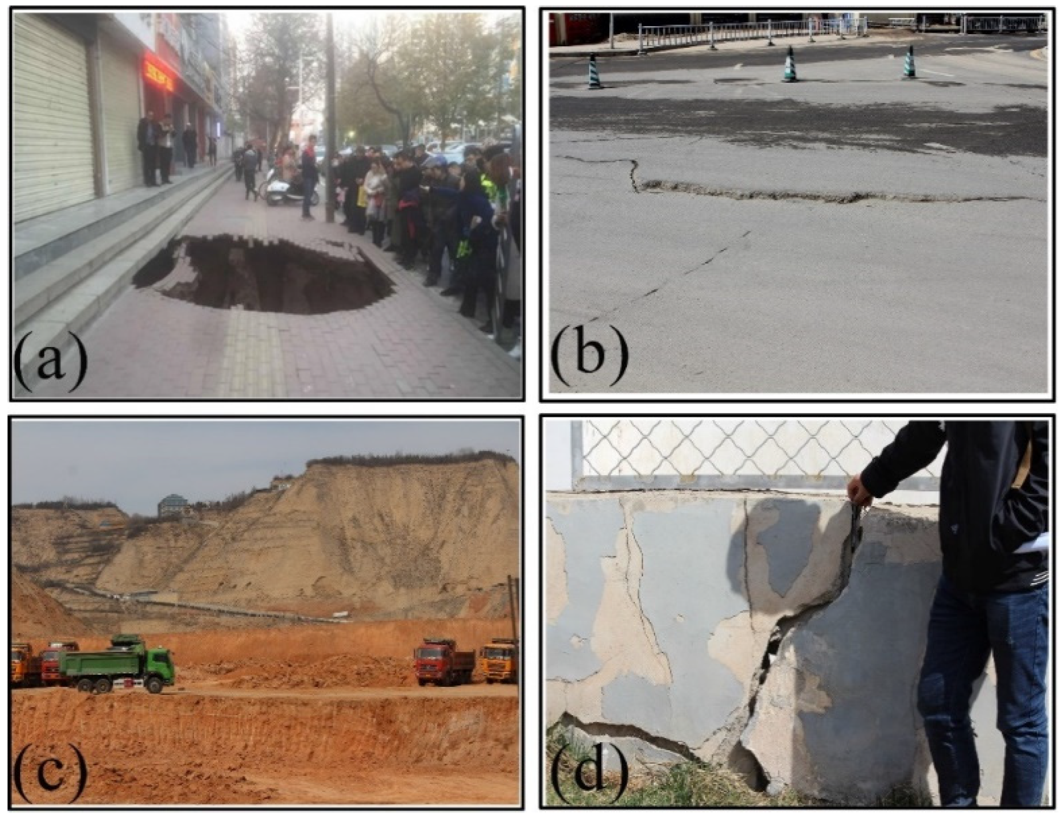
Figure 1. Surface deformation observed in Lanzhou. (a) ground collapses, (b) road ground sinks, (c) creating new land areas by cutting through the mountains and (d) cracks and openings in the wall.
Geosciences 10 00099 g001
Figure 2. The location of the study area. (A) The location on the map and (B) detailed distribution of municipal areas of Lanzhou.
Geosciences 10 00099 g002
Figure 3. Schematic of the Small Baseline Subset (SBAS) configuration of the Sentinel-1A images.
Geosciences 10 00099 g003
Figure 4. Schematic of the Permanent Scatterer (PS) configuration of the Sentinel-1A images.
Geosciences 10 00099 g004
Figure 5. Distribution of the differences in the PS-InSAR and SBAS-InSAR results.
Geosciences 10 00099 g005
Figure 6. The mean surface deformation rate map of Lanzhou.
Geosciences 10 00099 g006
Figure 7. Time-series land surface deformation map.
Geosciences 10 00099 g007
Figure 8. Time-series land surface deformation map for Regions P1−P7.
Geosciences 10 00099 g008
Figure 9. The Mann–Kendall test surface deformation trend analysis results for Regions P1−P7 during 2015−2019.
Geosciences 10 00099 g009
Figure 10. Distribution of the geology in the study area.
Geosciences 10 00099 g010
Figure 11. Distribution of the deformation rate and geological faults.
Geosciences 10 00099 g011
Figure 12. Relationship between surface deformation and geological faults (red line shows the fault lines). (a) deformation velocity for the A-A’ profile, (b) deformation velocity for the B-B’ profile, (c) deformation velocity for the C-C’ profile, (d) deformation velocity for the D-D’ profile, (e) deformation velocity for the E-E’ profile, (f) deformation velocity for the F-F’ profile and (g) deformation velocity for the G-G’ profile.
Geosciences 10 00099 g012
Figure 13. Land cover changes in the study area.
Geosciences 10 00099 g013
Table 1. Sentinel-1A data used in the study area.
Acquisition DateAcquisition DateAcquisition DateFlight Direction
14 March 20152 November 201628 December 2017Descending
7 April 20159 November 20169 January 2018Descending
1 May 201526 November 201621 January 2018Descending
25 May 20153 December 20162 February 2018Descending
18 June 201527 December 201626 February 2018Descending
12 July 201520 January 201710 March 2018Descending
5 August 20156 February 20179 May 2018Descending
29 August 201513 February 201721 May 2018Descending
22 September 201515 March 20172 June 2018Descending
16 October 201520 April 201714 June 2018Descending
9 November 20152 May 201726 June 2018Descending
3 December 201526 May 20178 July 2018Descending
20 January 20167 June 201713 August 2018Descending
13 February 201619 June 20176 September 2018Descending
8 March 201613 July 201730 September 2018Descending
1 April 201625 July 201712 October 2018Descending
25 April 20166 August 201724 October 2018Descending
19 May 201618 August 20175 November 2018Descending
12 June 201630 August 20174 January 2019Descending
30 July 201611 September 201728 January 2019Descending
23 August 201623 September 20175 March 2019Descending
16 September 20165 October 201729 March 2019Descending
21 September 201610 November 201710 April 2019Descending
27 September 201622 November 201722 April 2019Descending
16 October 20164 December 20174 May 2019Descending
Table 2. Statistical analysis results.
Interval ValueCountsCumulative Percentage
−7510.0049%
−6530.0148%
−5500.0000%
−4550.0246%
−35150.0739%
−25670.3302%
−156273.0902%
−5818240.3253%
5984348.5116%
1514036.9147%
251140.5619%
35150.0739%
45110.0542%
5530.0148%
6500.0000%
7510.0049%
Table 3. Summary of the observations in the seven studied areas: locations, maximum deformation rate, correlation between velocity gradients and locations of pre-existing geological faults, relationship to land cover types (agricultural, industrial and urban).
LocationsMax Deformation (mm)Correlation with Main GeologyCorrelation with FaultsCorrelation with Land Cover Types
P1−115.07Holocene Aeolian GroupFault-limitedUrban
P2−183.11Xiliugou GroupFault-limitedUrban
P3−211.92Hekou Group and Upper Pleistocene Aeolian GroupFault-limitedUrban
P4−132.07Upper Pleistocene Aeolian GroupFault-limitedIndustry
P5−132.54Upper Pleistocene Aeolian GroupFault-limitedUrban
P6−109.04Upper Pleistocene Aeolian GroupFault-limitedUrban
P7−142.20Upper Pleistocene Aeolian GroupFault-limitedAgriculture