Combined Use of 3D Metric Survey and GPR for the Diagnosis of the Trapezophoros with Two Griffins Attacking a Doe of Ascoli Satriano (Foggia, Italy)
Abstract
1. Introduction
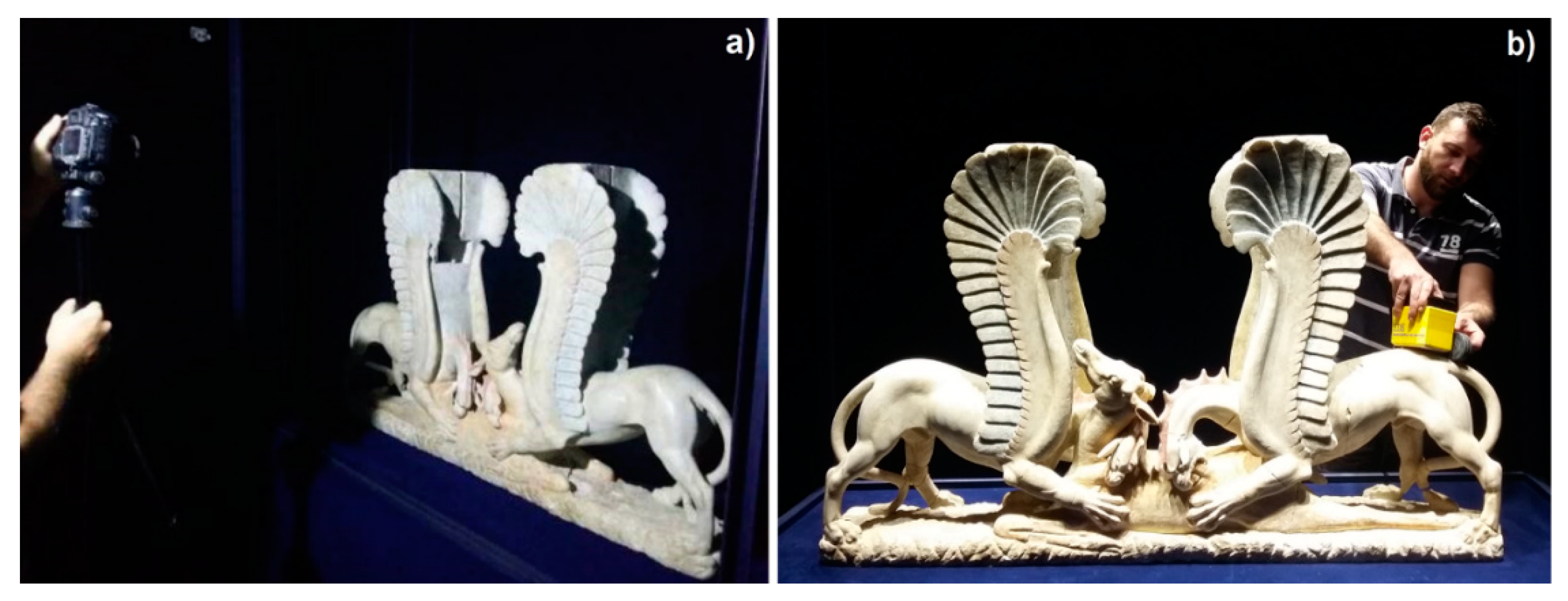
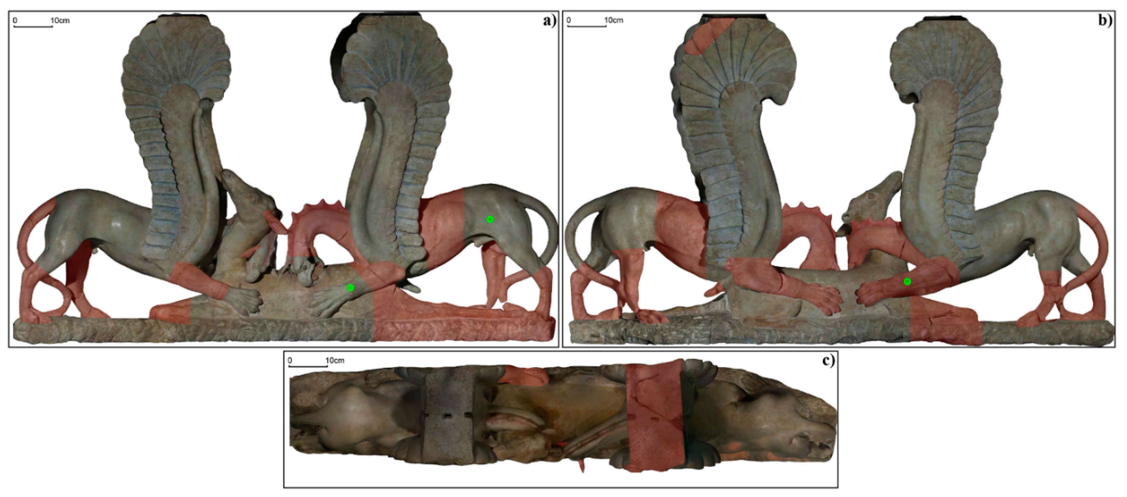
- The creation of a high-resolution 3D model and orthophotos of the external surfaces through a photogrammetry digital survey (Figure 1a) in order to highlight the decay and even the type, which is not perceivable by direct sight.
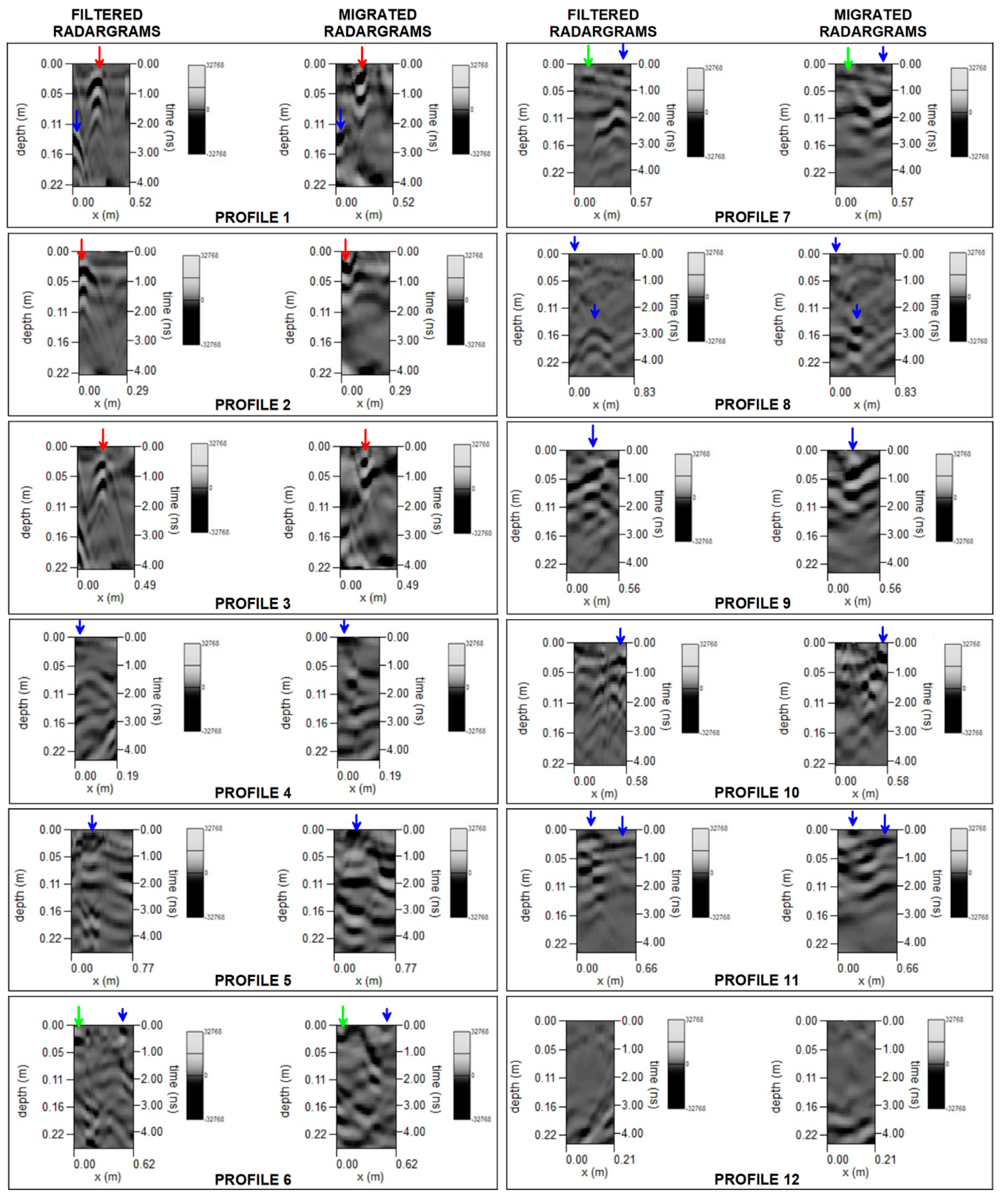
- An analysis of the inner surfaces through the implementation of noninvasive GPR surveys (Figure 1b), with the purpose of detecting anomalies and possibly indicating voids or fractures.
- The production of new and detailed documentation, which has been nonexistent so far and which is useful for planning future conservation actions.
2. Materials and Methods
2.1. Photogrammetric Digital Survey
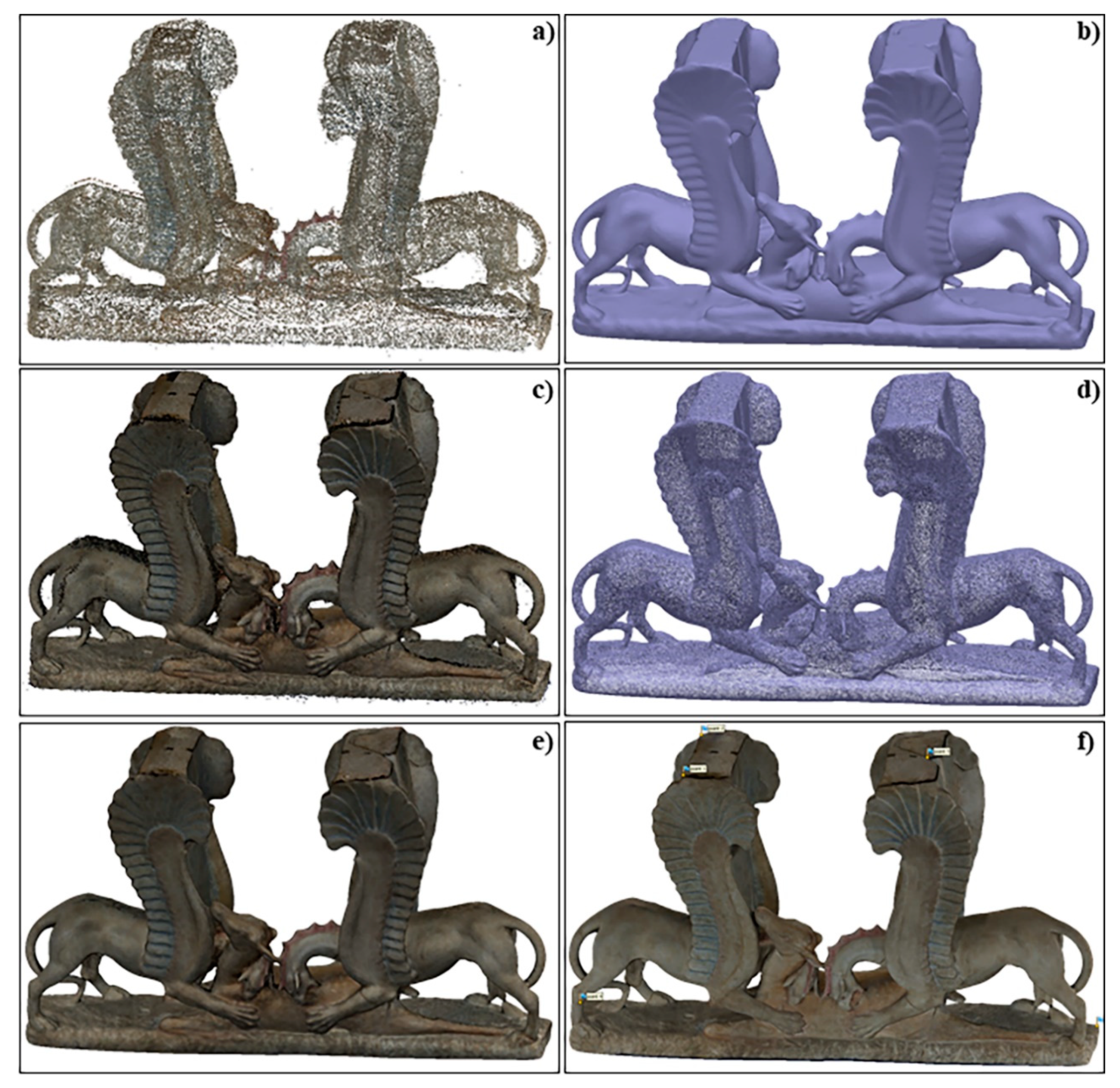
- Frame alignment through the Structure-from-Motion (SfM) technique [52,53]. A sparse point cloud consisting of 308,196 points that describes the object’s geometry (Figure 2a), and the camera positions at the frame captures were obtained using the “medium alignment” (key point limit: 40,000 and tie point limit: 4000).
- Construction of the geometry through dense cloud portrayed by 5,720,932 points (Figure 2b) using the “medium build dense cloud” settings.
- Mesh production in which the point cloud was transformed onto a surface consisting of 380,785 triangulated dots (Figure 2c–e). In order to recognize and fit discontinuities on the model, the “multiresolution model” routine based on automated algorithms was used [54]. Furthermore, the “optimization method” and the “decimation filter” were applied for rearranging and smoothing, respectively, the nodes of the triangles and for simplifying the model and generating a multiresolution model.
- Positioning the 3D model in Cartesian space in real metric units with a total station. The coordinates of the topographic survey were introduced, placing ground control point (GCP) markers on each frame, which exist in multiple images, obtaining an average registration error relative to the entire photogrammetric survey of about 3 mm (Figure 2f).
- Construction of the texture through the application of the photographic images to the 3D digital model (Figure 2f and Figure 3). The “generic mapping mode” was used to create a texture as uniform as possible, and the “mosaic blending mode” was used for avoiding seam line problems and for blending low and high-frequency components regarding overlapping images.
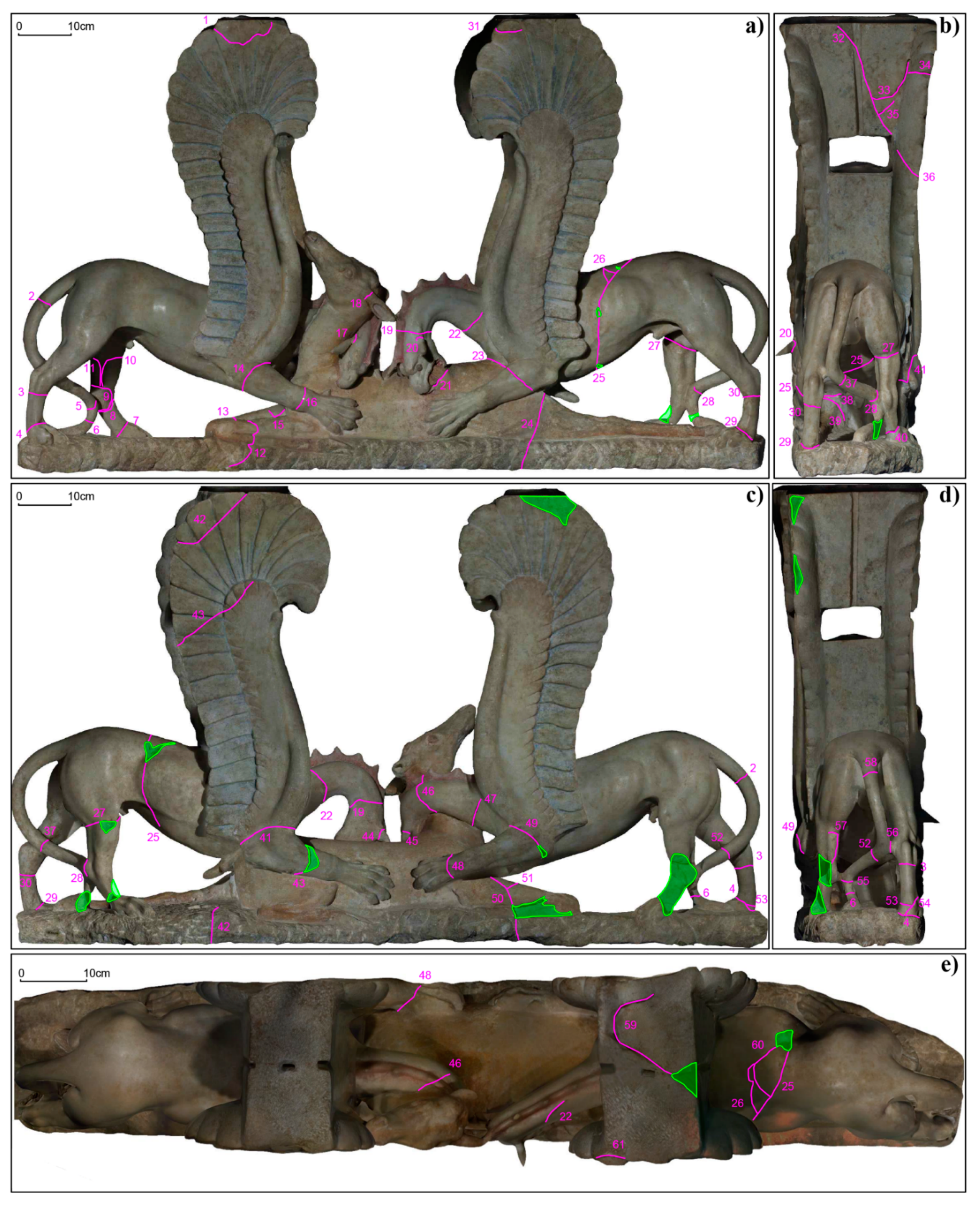
- Creation of orthophotos of the visible surfaces with a resolution of 1.56 mm/pix (Figure 4).
2.2. GPR Survey and Data Processing
3. Results
- Type 1: oblique and subvertical fractures with an average thickness of greater than 1 mm and, in some cases, up to 3 mm. The fractures 4, 5, 7–12, 14–18, 21–25, 28, 29, 32, 33, 35, 36, 39, 42–44, 46–50, 52, 54, and 56 are part of this class.
- Type 2: sub-horizontal fractures with an average thickness of greater than 1 mm, such as lesions 1–3, 6, 19–20, 27, 30, 31, 34, 38, 40, 41, 45, 51, 53, 55, and 58.
- Type 3: composite fractures that are characterized by the union or intersection of the types mentioned above, such as cracks 9–11, 26, 57, 59, and 60. They have an average thickness greater or equal to 1 mm.
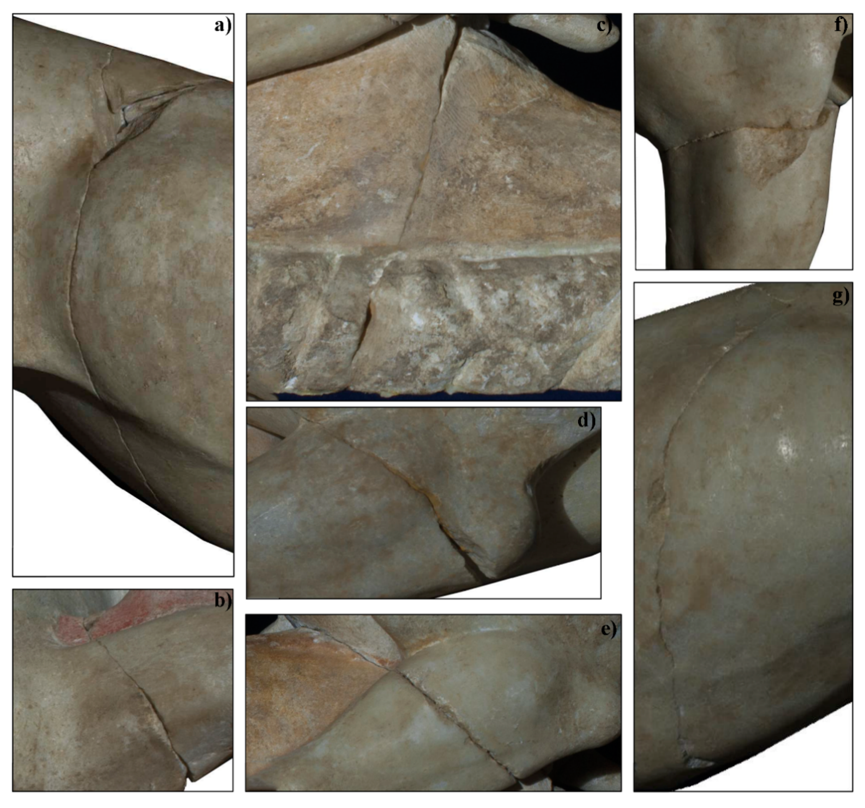
- Fracture 25 (Figure 7a,g), which develops transversely to the body of the right griffin (type 1, >1 mm),
- Fracture 22 (Figure 7b), which affects the neck of the griffin on the right (type 1, >1 mm),
- Fracture 24 (Figure 7c), which cuts transversely across the hind legs of the doe and the base of the support of the sculpture (type 1, >2 mm),
- Fracture 49 (Figure 7d), which develops transversely to the left front leg of the left griffon (type 1, >2 mm),
- Fracture 23 (Figure 7e), which is present on the left front leg of the right griffon and on the back of the doe (type 1, >1 mm), and
- Fracture 27 (type 2, >2 mm), which cuts transversely the right rear leg of the right griffin (Figure 7f).
4. Conclusions
Author Contributions
Funding
Acknowledgments
Conflicts of Interest
References
- Ghetti, L.M. (Ed.) Capolavori Dell’archeologia: Recuperi, Ritrovamenti, Confronti; Gangemi Editore spa: Roma, Italy, 2013. [Google Scholar]
- Bottini, A.; Setari, E. Il complesso di marmi da Ausculum. In Il Segreto di Marmo. I Marmi Dipinti di Ascoli Satriano; catalogo della mostra Il segreto di marmo, Museo Nazionale Romano, 16 dicembre 2009-18 aprile 2010, Roma; Bottini, A., Setari, E., Eds.; Electa: Milano, Italy, 2009. [Google Scholar]
- Cassano, R. (Ed.) Principi, Imperatori, Vescovi—Duemila Anni di Storia a Canosa; catalogo della mostra di Bari; Marsilio Editore: Venezia, Italy, 1992; pp. 206, 218. [Google Scholar]
- Bentz, M. Eine Weihung von Reliefgefäßen im Diana-Heiligtum am Nemi-See. Boreas 1998, 21, 185–196. [Google Scholar]
- Lullies, R. Vergoldete Terrakotta-Appliken aus Tarent (7 Erg. RM); FH Kerle: Heidelberg, Germany, 1962; p. 74, tav. 17. [Google Scholar]
- De Juliis, E. Gli ori di Taranto in età Ellenistica (Catalogo Della Mostra di Milano); Mondadori: Milano, Italy, 1984; p. 393. [Google Scholar]
- Godart, L.; De Caro, S. (Eds.) Nostoi: Capolavori Ritrovati; catalogo della mostra, Roma, Quirinale, 23 marzo-20 maggio 2007; Segretariato generale della presidenza della Repubblica: Roma, Italy, 2007.
- Pellegrini, M. Intrigo Internazionale. In Archeo; Timeline Publishing srl: Roma, Italy, 2016; p. 375. [Google Scholar]
- Isman, F. I Predatori Dell’arte perduta. Il Saccheggio Dell’archeologia in Italia; Skira: Milano, Italy, 2009. [Google Scholar]
- The Museum Complex of Ascoli Satriano. Available online: http://polomusealeascolisatriano.blogspot.it/ (accessed on 15 April 2020).
- Cozzolino, M.; Di Giovanni, E.; Mauriello, P.; Piro, S.; Zamuner, D. Geophysical Methods for Cultural Heritage Management; Springer: Cham, Switzerland, 2018. [Google Scholar] [CrossRef]
- Brizzolari, E.; Cardarelli, E.; Piro, S.; Versino, L. Detection of subsurface magnetic anomalies of archaeological interest: Computation of tridimensional magnetic anomalies and interpretation using bidimensional cross-correlation. TPAG 1993, 7, 3–16. [Google Scholar]
- Fassbinder, J.W.E.; Reindel, M. Magnetometer prospection as research for pre-Spanish cultures at Nasca and Palpa, Perù. In Proceedings of the 6th International Archaeological Prospection Conference, Rome, Italy, 14–17 September 2005; Piro, S., Ed.; CNR: Roma, Italy, 2005; pp. 6–10. [Google Scholar]
- Scollar, I. Electromagnetic Prospecting Methods in Archaeology. Archaeometry 1962, 5, 146–153. [Google Scholar] [CrossRef]
- Tabbagh, A. Applications and Advantages of the Slingram Electromagnetic Method for Archaeological Prospecting. Geophysics 1986, 51, 576–584. [Google Scholar] [CrossRef]
- Tsokas, G.N.; Giannopoulos, A.; Tsourlos, P.; Vargemezis, G.; Tealby, J.M.; Sarris, A.; Papazachos, C.B.; Savopoulou, T. A large scale geophysical survey in the archaeological site of Europos (northern Greece). J. Appl. Geophys. 1994, 32, 85–98. [Google Scholar] [CrossRef]
- Papadopoulos, N.G.; Tsourlos, P.; Tsokas, G.N.; Sarris, A. Two-dimensional and three-dimensional resistivity imaging in archaeological site investigation. Archaeol. Prospect. 2006, 13, 163–181. [Google Scholar] [CrossRef]
- Compare, V.; Cozzolino, M.; Mauriello, P.; Patella, D. 3D Resistivity probability tomography at the prehistoric site of Grotta Reali (Molise, Italy). Archaeol. Prospect. 2009, 16, 53–63. [Google Scholar] [CrossRef]
- Compare, V.; Cozzolino, M.; Mauriello, P.; Patella, D. Resistivity Probability Tomography Imaging at the Castle of Zena, Italy. EURASIP J. Image Video Process. 2009, 2009, 1–9. [Google Scholar] [CrossRef]
- Minelli, A.; Cozzolino, M.; Di Nucci, A.; Guglielmi, S.; Giannantonio, M.; D’Amore, D.; Pittoni, E.; Groot, A.M. The prehistory of the Colombian territory: The results of the Italian archaeological investigation on the Checua site (Municipality of Nemocòn, Cundinamarca Department). J. Biol. Res. 2012, 85, 94–97. [Google Scholar] [CrossRef]
- Cozzolino, M.; Mauriello, P.; Patella, D. Resistivity Tomography Imaging of the substratum of the Bedestan Monumental Complex at Nicosia, Cyprus. Archaeometry 2014, 56, 331–350. [Google Scholar] [CrossRef][Green Version]
- Cozzolino, M.; Di Giovanni, E.; Mauriello, P.; Vanni Desideri, A.; Patella, D. Resistivity tomography in the Park of Pratolino at Vaglia (Florence, Italy). Archaeol. Prospect. 2012, 19, 253–260. [Google Scholar] [CrossRef]
- Lentini, M.C.; Pakkanen, J.; Sarris, A. Naxos of Sicily in the 5th Century BC: New Research. In Greek Colonization. New Data, Current Approaches, Proceedings of the Scientific Meeting Held in Thessaloniki, Thessaloniki, Greece, 6 February 2015; Veleni, P., Tsagari, D., Eds.; Alpha Bank: Athens, Greece, 2015; pp. 23–35. [Google Scholar]
- Cozzolino, M.; Longo, F.; Pizzano, N.; Rizzo, M.L.; Voza, O.; Amato, V. Multidisciplinary Approach to the Study of the Temple of Athena in Poseidonia-Paestum (Southern Italy): New Geomorphological, Geophysical and Archaeological Data. Geosciences 2019, 9, 324. [Google Scholar] [CrossRef]
- Cozzolino, M.; Caliò, L.M.; Gentile, V.; Mauriello, P.; Di Meo, A. The Discovery of the Theater of Akragas (Valley of Temples, Agrigento, Italy): An Archaeological Confirmation of the Supposed Buried Structures from a Geophysical Survey. Geosciences 2020, 10, 161. [Google Scholar] [CrossRef]
- Goodman, D.; Nishimura, Y. A Ground-radar view of Japanese burial mounds. Antiquity 1993, 67, 349–354. [Google Scholar] [CrossRef]
- Nishimura, Y.D.; Goodman, D. Ground-penetrating radar survey at Wroxeter. Archaeol. Prospect. 2000, 7, 101–105. [Google Scholar] [CrossRef]
- Amato, V.; Cozzolino, M.; De Benedittis, G.; Di Paola, G.; Gentile, V.; Giordano, C.; Marino, P.; Rosskopf, C.M.; Valente, E. An integrated quantitative approach to assess the archaeological heritage in highly anthropized areas: The case study of Aesernia (southern Italy). Acta IMECO 2016, 5, 33–43. [Google Scholar] [CrossRef]
- Cozzolino, M.; Baković, M.; Borovinić, N.; Galli, G.; Gentile, V.; Jabučanin, M.; Mauriello, P.; Merola, P.; Živanović, M. The contribution of geophysics to the knowledge of the hidden archaeological heritage of Montenegro. Geoscience 2020, 10, 187. [Google Scholar] [CrossRef]
- Cozzolino, M.; Gentile, V.; Giordano, C.; Mauriello, P. Imaging buried archaeological features through Ground Penetrating Radar: The case of the ancient Saepinum (Campobasso, Italy). Geoscience 2020, 10, 225. [Google Scholar] [CrossRef]
- Avdelidis, N.P.; Moropoulou, A. Applications of infrared thermography for the investigation of historic structures. J. Cult. Heritage 2004, 5, 119–127. [Google Scholar] [CrossRef]
- Burrows, S.E.; Rashed, A.; Almond, D.P.; Dixon, S. Combined laser spot imaging thermography and ultrasonic measurements for crack detection. Nondestruct. Test. Eval. 2007, 22, 217–227. [Google Scholar] [CrossRef]
- Kandemir-Yucel, A.; Tavukcuoglu, A.; Caner-Saltik, E.N. In situ assessment of structural timber elements of a historic building by infrared thermography and ultrasonic velocity. Infrared Phys. Technol. 2007, 49, 243–248. [Google Scholar] [CrossRef]
- Bavusi, M.; Soldovieri, F.; Piscitelli, S.; Loperte, A.; Vallianatos, F.; Soupios, P. Ground penetrating radar and microwave tomography to evaluate the crack and joint geometry in historical buildings: Some examples from Chania, Crete, Greece. Near Surf. Geophys. 2010, 8, 377–387. [Google Scholar] [CrossRef]
- Candoré, J.C.; Bodnar, J.L.; Detalle, V.; Grossel, P. Non-destructive testing in situ, of works of art by stimulated infrared thermography. J. Phys. Conf. Ser. 2010, 214, 012068. [Google Scholar] [CrossRef]
- Danese, M.; Demšar, U.; Masini, N.; Charlton, M. Investigating material decay of historic buildings using visual analytics with multi-temporal infrared thermographic data. Archaeometry 2010, 52, 482–501. [Google Scholar] [CrossRef]
- Carlomagno, G.M.; Di Maio, R.; Fedi, M.; Meola, C. Integration of infrared thermography and highfrequency electromagnetic methods in archaeological surveys. J. Geophys. Eng. 2011, 8, 93–105. [Google Scholar] [CrossRef]
- Leucci, G.; Masini, N.; Persico, R.; Soldovieri, F. GPR and sonic tomography for structural restoration: The case of the cathedral of Tricarico. J. Geophys. Eng. 2011, 8, 76–92. [Google Scholar] [CrossRef]
- Sambuelli, L.; Bhom, G.; Capizzi, P.; Cardarelli, E.; Cosentino, P. Comparison between GPR measurements and ultrasonic tomography with different inversion algorithms: An application to the base of an ancient Egyptian sculpture. J. Geophys. Eng. 2011, 8, 106–116. [Google Scholar] [CrossRef]
- Bodnar, L.; Candoré, J.C.; Nicolas, J.L.; Szatanik, G.; Detalle, V.; Vallet, J.M. Stimulated infrared thermography applied to help restoring mural paintings. J. NDT E Int. 2012, 49, 40–46. [Google Scholar] [CrossRef]
- Knudson, D.L.; Rempe, J.L. Linear Variable Differential Transformer (LVDT)-based elongation Measurements in Advanced Test Reactor high temperature irradiation testing. Meas. Sci. Technol. 2012, 23, 025604. [Google Scholar] [CrossRef]
- Alani, A.M.; Aboutalebi, M.; Kilic, G. Applications of ground penetrating radar (GPR) in bridge deck monitoring and assessment. J. Appl. Geophys. 2013, 97, 45–54. [Google Scholar] [CrossRef]
- Kadioglu, S.; Kadioglu, Y.K.; Catapano, I.; Soldovieri, F. Ground penetrating radar and microwave tomography for the safety management of a cultural heritage site: Miletos Ilyas Bey Mosque (Turkey). J. Geophys. Eng. 2013, 10, 064007. [Google Scholar] [CrossRef]
- Catapano, I.; Gennarelli, G.; Ludeno, G.; Soldovieri, F. Applying Ground-Penetrating Radar and Microwave Tomography Data Processing in Cultural Heritage: State of the art and future trends. IEEE Signal. Process. Mag. 2019, 36, 53–61. [Google Scholar] [CrossRef]
- Arias, P.; Armesto, J.; Di-Capua, D.; González-Drigo, R.; Lorenzo, H.; Pérez-Gracia, V. Digital photogrammetry, GPR and computational analysis of structural damages in a mediaeval bridge. Eng. Fail. Anal. 2007, 14, 1444–1457. [Google Scholar] [CrossRef]
- Oses, N.; Dornaika, F.; Moujahid, A. Image-based delineation and classification of built heritage masonry. Remote Sens. 2014, 6, 1863–1889. [Google Scholar] [CrossRef]
- Costanzo, A.; Minasi, M.; Casula, G.; Musacchio, M.; Buongiorno, M.F. Combined use of terrestrial laser scanning and IR thermography applied to a historical building. Sensor 2015, 15, 194–213. [Google Scholar] [CrossRef]
- Barrile, V.; Bilotta, G.; Meduri, G.M.; De Carlo, D.; Nunnari, A. Laser Scanner technology, ground−penetrating radar and augmented reality for the survey and recovery of the artistic, archaeological and cultural heritage. ISPRS Ann. Photogramm. Remote Sens. Spat. Inf. Sci. 2017, 123–127. [Google Scholar] [CrossRef]
- Danese, M.; Sileo, M.; Masini, M. Geophysical Methods and Spatial Information for the Analysis of Decay frescoes. Surv. Geophys. 2018, 6, 1149–1166. [Google Scholar] [CrossRef]
- Cozzolino, M.; Gabrielli, R.; Galatà, P.; Gentile, V.; Greco, G.; Scopinaro, E. Combined use of 3D metric surveys and non-invasive geophysical surveys for the determination of the state of conservation of the Stylite Tower (Umm ar-Rasas, Jordan). Ann. Geophys. 2019, 61, 72. [Google Scholar] [CrossRef]
- Cozzolino, M.; Di Meo, A.; Gentile, V. The contribution of indirect topographic surveys (photogrammetry and the laser scanner) and GPR investigations in the study of the vulnerability of the Abbey of Santa Maria a Mare, Tremiti Islands (Italy). Ann. Geophys. 2019, 61, 71. [Google Scholar] [CrossRef]
- Remondino, F.; El−Hakim, S. Image-based 3-D modelling: A review. Photogramm. Rec. 2006, 21, 269–291. [Google Scholar] [CrossRef]
- Remondino, F.; El-Hakim, S.F.; Gruen, A.; Zhang, L. Turning images into 3-D models. IEEE Signal Process. Mag. 2008, 25, 55–65. [Google Scholar] [CrossRef]
- Angelini, A.; Portarena, D. Advice for archaeological survey with recent technologies. Acta IMEKO 2018, 7, 42–51. [Google Scholar] [CrossRef]
- GPR-SLICE Software. Available online: http://www.gprsurvey.com/practice/GPR-SLICE (accessed on 15 March 2020).
- Jol, H. Ground Penetrating Radar: Theory and Applications; Elsevier: Amsterdam, The Netherlands, 2009. [Google Scholar]
- Evans, R.D. Optimising Ground Penetrating Radar (GPR) to Assess Pavements. Ph.D. Thesis, Loughborough University, Loughborough, UK, August 2009. [Google Scholar]
- Conyers, L.B.; Goodman, B. Ground-Penetrating Radar: An Introduction for Archaeologists; AltaMira Press: Walnut Creek, CA, USA; London, UK; New Delhi, India, 1997; p. 232. [Google Scholar]




© 2020 by the authors. Licensee MDPI, Basel, Switzerland. This article is an open access article distributed under the terms and conditions of the Creative Commons Attribution (CC BY) license (http://creativecommons.org/licenses/by/4.0/).
Share and Cite
Cozzolino, M.; Di Meo, A.; Gentile, V.; Mauriello, P.; Zullo, E. Combined Use of 3D Metric Survey and GPR for the Diagnosis of the Trapezophoros with Two Griffins Attacking a Doe of Ascoli Satriano (Foggia, Italy). Geosciences 2020, 10, 307. https://doi.org/10.3390/geosciences10080307
Cozzolino M, Di Meo A, Gentile V, Mauriello P, Zullo E. Combined Use of 3D Metric Survey and GPR for the Diagnosis of the Trapezophoros with Two Griffins Attacking a Doe of Ascoli Satriano (Foggia, Italy). Geosciences. 2020; 10(8):307. https://doi.org/10.3390/geosciences10080307
Chicago/Turabian StyleCozzolino, Marilena, Andrea Di Meo, Vincenzo Gentile, Paolo Mauriello, and Enza Zullo. 2020. "Combined Use of 3D Metric Survey and GPR for the Diagnosis of the Trapezophoros with Two Griffins Attacking a Doe of Ascoli Satriano (Foggia, Italy)" Geosciences 10, no. 8: 307. https://doi.org/10.3390/geosciences10080307
APA StyleCozzolino, M., Di Meo, A., Gentile, V., Mauriello, P., & Zullo, E. (2020). Combined Use of 3D Metric Survey and GPR for the Diagnosis of the Trapezophoros with Two Griffins Attacking a Doe of Ascoli Satriano (Foggia, Italy). Geosciences, 10(8), 307. https://doi.org/10.3390/geosciences10080307


