
Evaluation of the Static Design Procedure in the Canadian Foundation Engineering Manual for Piles in Cohesionless Soil


Abstract
:1. Introduction
2. Pile Load Tests
3. Interpretation of the Friction Angle Used in the Design
4. The Theoretical Static Pile Design Method for Cohesionless Soils According to the CFEM
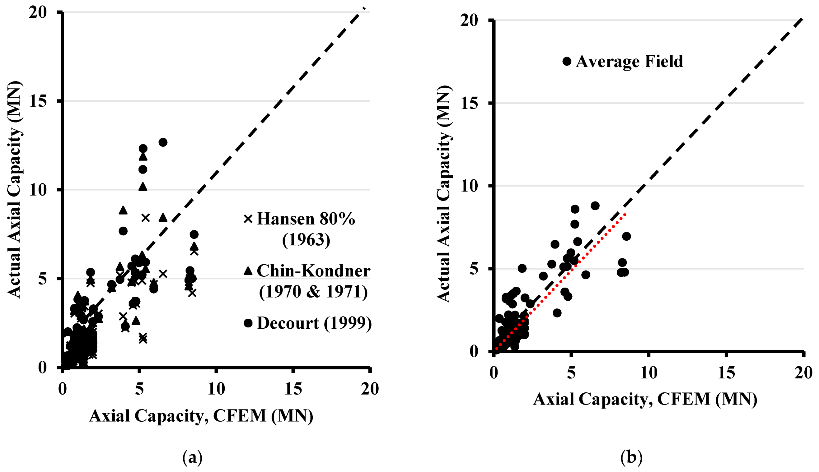
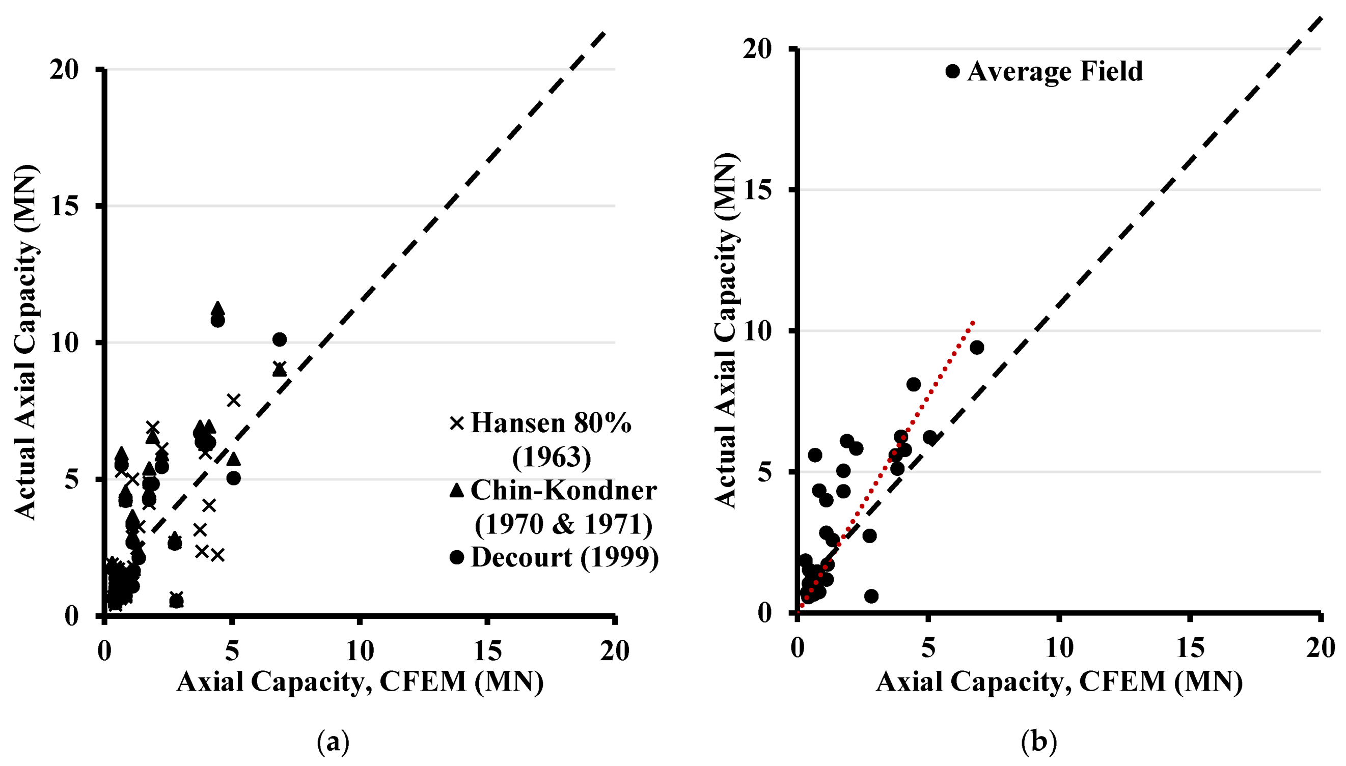
5. Assessment of the CFEM Method for Estimating the Ultimate Pile Capacity in Cohesionless Soils
6. Summary and Conclusions
Author Contributions
Funding
Data Availability Statement
Conflicts of Interest
Appendix A

| Pile Test No. | Pile Location | Loading Type | Pile Material | Pile Shape | Length (m) | Width/Diameter (m) | Thickness (m) | Reference |
|---|---|---|---|---|---|---|---|---|
| 1 | Wuhu, China | compression | concrete | open circular | 33 | 0.6 | 0.13 | Yang et al., 2015a |
| 2 | Wuhu, China | compression | concrete | open circular | 39.8 | 0.6 | 0.13 | Yang et al., 2015a |
| 3 | Wuhu, China | compression | concrete | open square | 39.8 | 0.5 | 0.095 | Yang et al., 2015a |
| 4 | Wuhu, China | compression | concrete | open circular | 29.3 | 0.6 | 0.13 | Yang et al., 2015a |
| 5 | Wuhu, China | compression | concrete | open circular | 29.2 | 0.8 | 0.13 | Yang et al., 2015a |
| 6 | Rio de Janeiro Brazil | compression | concrete | square | 37.2 | 0.5 | 0 | Tsuha et al., 2012 |
| 7 | Rio de Janeiro Brazil | compression | concrete | square | 21.4 | 0.5 | 0 | Tsuha et al., 2012 |
| 8 | Rio de Janeiro Brazil | compression | concrete | square | 35.6 | 0.7 | 0 | Tsuha et al., 2012 |
| 9 | Rio de Janeiro Brazil | compression | concrete | square | 26.5 | 0.5 | 0 | Tsuha et al., 2012 |
| 10 | Blessington Dublin, Ireland | tension | steel | open circular | 7 | 0.34 | 0.014 | Gavin et al., 2013 |
| 11 | Blessington Dublin, Ireland | tension | steel | open circular | 7 | 0.34 | 0.014 | Gavin et al., 2013 |
| 12 | Horstwalde, Germany | tension | steel | open circular | 17.61 | 0.711 | 0.0125 | Rucker et al., 2013 |
| 13 | Horstwalde, Germany | tension | steel | open circular | 17.69 | 0.711 | 0.025 | Rucker et al., 2013 |
| 14 | Horstwalde, Germany | tension | steel | open circular | 17.71 | 0.711 | 0.0125 | Rucker et al., 2013 |
| 15 | Horstwalde, Germany | tension | steel | open circular | 17.76 | 0.711 | 0.0125 | Rucker et al., 2013 |
| 16 | Horstwalde, Germany | tension | steel | open circular | 17.67 | 0.711 | 0.0125 | Rucker et al., 2013 |
| 17 | Horstwalde, Germany | tension | steel | open circular | 17.66 | 0.711 | 0.0125 | Rucker et al., 2013 |
| 18 | Horstwalde, Germany | tension | steel | open circular | 17.63 | 0.711 | 0.0125 | Rucker et al., 2013 |
| 19 | Horstwalde, Germany | tension | steel | open circular | 17.74 | 0.711 | 0.0125 | Rucker et al., 2013 |
| 20 | British Columbia, Canada | compression | steel | circular | 45 | 0.61 | 0 | Naesgaard et al., 2012 |
| 21 | Hampton, Virginia, USA | compression | concrete | square | 16.8 | 0.61 | 0 | Pando et al., 2003 |
| 22 | Rotterdam Harbor, The Netherlands | compression | concrete | square | 30.6 | 0.38 | 0 | Gijt et al., 1995 |
| 23 | Rotterdam Harbor, The Netherlands | compression | concrete | square | 30.3 | 0.38 | 0 | Gijt et al., 1995 |
| 24 | Rotterdam Harbor, The Netherlands | compression | concrete | square | 30.7 | 0.38 | 0 | Gijt et al., 1995 |
| 25 | Waddinxveen Site, The Netherlands | compression | concrete | square | 10 | 0.35 | 0 | Holscher et al., 2008 |
| 26 | Mobile Bay, AL, USA | compression | steel | open circular | 15.2 | 0.324 | 0.0254 | Mayne & Niazi, 2013 |
| 27 | ABEF Foundation, Brazil | compression | concrete | open circular | 9 | 0.5 | 0.09 | Mayne & Niazi, 2013 |
| 28 | ABEF Foundation, Brazil | compression | concrete | open circular | 7.5 | 0.5 | 0.09 | Mayne & Niazi 2013 |
| 29 | Apalachicola River, USA | compression | concrete | square | 29.9 | 0.61 | 0 | Mayne & Niazi 2013 |
| 30 | Los Angeles, CA Site, USA | compression | concrete | square | 29 | 0.61 | 0 | Mayne & Niazi 2013 |
| 31 | MS Smith, USA | compression | concrete | square | 10.2 | 0.41 | 0 | Mayne & Niazi 2013 |
| 32 | MS Desota, USA | compression | concrete | square | 7.6 | 0.46 | 0 | Mayne & Niazi 2013 |
| 33 | MS Harrison, USA | compression | concrete | square | 7.6 | 0.46 | 0 | Mayne & Niazi 2013 |
| 34 | Washington MS, USA | compression | concrete | square | 7.6 | 0.41 | 0 | Mayne & Niazi 2013 |
| 35 | Washington MS, USA | compression | concrete | square | 16.6 | 0.36 | 0 | Mayne & Niazi 2013 |
| 36 | Washington MS, USA | compression | concrete | square | 6.18 | 0.36 | 0 | Mayne & Niazi 2013 |
| 37 | Larvik, Norway | tension | steel | open circular | 21.5 | 0.508 | 0.0063 | Karlsrud 2014 |
| 38 | Larvik, Norway | tension | steel | open circular | 21.5 | 0.508 | 0.0063 | Karlsrud 2014 |
| 39 | Larvik, Norway | tension | steel | open circular | 21.5 | 0.508 | 0.0063 | Karlsrud 2014 |
| 40 | Larvik, Norway | tension | steel | open circular | 21.5 | 0.508 | 0.0063 | Karlsrud 2014 |
| 41 | Larvik, Norway | tension | steel | open circular | 21.5 | 0.508 | 0.0063 | Karlsrud 2014 |
| 42 | Larvik, Norway | tension | steel | open circular | 21.5 | 0.508 | 0.0063 | Karlsrud 2014 |
| 43 | Larvik, Norway | tension | steel | open circular | 21.5 | 0.508 | 0.0063 | Karlsrud 2014 |
| 44 | Jackson Country, USA | compression | steel | circular | 17.8 | 0.273 | 0 | Mayne & Elhakim 2002 |
| 45 | Lafayette Bridge, USA | compression | steel | circular | 20.29 | 0.356 | 0 | Komurka et al., 2010 |
| 46 | Ogechee River, USA | compression | concrete | square | 15.2 | 0.406 | 0 | Vesic 1970 |
| 47 | Ogechee River, USA | compression | steel | circular | 6.1 | 0.457 | 0 | Vesic 1970 |
| 48 | Ogechee River, USA | compression | steel | circular | 8.9 | 0.457 | 0 | Vesic 1970 |
| 49 | Ogechee River, USA | compression | steel | circular | 12 | 0.457 | 0 | Vesic 1970 |
| 50 | Ogechee River, USA | compression | steel | circular | 15 | 0.457 | 0 | Vesic 1970 |
| 51 | Drammen, Norway | compression | concrete | circular | 8 | 0.28 | 0 | Gregersen et al., 1973 |
| 52 | Drammen, Norway | compression | concrete | circular | 16 | 0.28 | 0 | Gregersen et al., 1973 |
| 53 | Drammen, Norway | compression | concrete | circular | 7.5 | 0.28 | 0 | Gregersen et al., 1973 |
| 54 | Drammen, Norway | compression | concrete | circular | 11.5 | 0.28 | 0 | Gregersen et al., 1973 |
| 55 | Drammen, Norway | compression | concrete | circular | 15.5 | 0.28 | 0 | Gregersen et al., 1973 |
| 56 | Drammen, Norway | compression | concrete | circular | 19.5 | 0.28 | 0 | Gregersen et al., 1973 |
| 57 | Drammen, Norway | compression | concrete | circular | 23.5 | 0.28 | 0 | Gregersen et al., 1973 |
| 58 | Drammen, Norway | tension | concrete | circular | 8 | 0.28 | 0 | Gregersen et al., 1973 |
| 59 | Drammen, Norway | tension | concrete | circular | 16 | 0.28 | 0 | Gregersen et al., 1973 |
| 60 | Drammen, Norway | tension | concrete | circular | 23.5 | 0.28 | 0 | Gregersen et al., 1973 |
| 61 | Hoogzand, The Netherlands | compression | steel | open circular | 5.3 | 0.356 | 0.02 | Beringen et al., 1979 |
| 62 | Hoogzand, The Netherlands | compression | steel | circular | 6.8 | 0.356 | 0 | Beringen et al., 1979 |
| 63 | Hunter’s Point, USA | compression | steel | circular | 7.8 | 0.273 | 0 | Briaud et al., 1989a |
| 64 | Leman BD, North Sea | tension | steel | open circular | 38.1 | 0.66 | 0.019 | Chow et al., 1998 |
| 65 | Baghdad University, Iraq | compression | concrete | square | 11 | 0.253 | 0 | Altaee et al., 1992 |
| 66 | Baghdad University, Iraq | tension | concrete | square | 11 | 0.253 | 0 | Altaee et al., 1992 |
| 67 | Baghdad University, Iraq | compression | concrete | square | 15 | 0.253 | 0 | Altaee et al., 1992 |
| 68 | Dunkirk CLAROM, France | tension | steel | open circular | 11.3 | 0.324 | 0.0127 | Chow 1997 |
| 69 | Dunkirk CLAROM, France | compression | steel | open circular | 11.3 | 0.324 | 0.0127 | Chow 1997 |
| 70 | Dunkirk GOPAL, France | tension | steel | open circular | 19.3 | 0.457 | 0.0135 | Jardine et al., 2006 |
| 71 | Dunkirk GOPAL, France | compression | steel | open circular | 10 | 0.457 | 0.0135 | Jardine et al., 2006 |
| 72 | Dunkirk GOPAL, France | tension | steel | open circular | 10 | 0.457 | 0.0135 | Jardine et al., 2006 |
| 73 | Locks and Dam, USA | compression | steel | circular | 14.2 | 0.305 | 0 | Briaud et al., 1989b |
| 74 | Locks and Dam, USA | compression | steel | circular | 14.4 | 0.356 | 0 | Briaud et al., 1989b |
| 75 | Locks and Dam, USA | compression | steel | circular | 14.6 | 0.406 | 0 | Briaud et al., 1989b |
| 76 | Locks and Dam, USA | tension | steel | circular | 11 | 0.305 | 0 | Briaud et al., 1989b |
| 77 | Locks and Dam, USA | tension | steel | circular | 11.1 | 0.305 | 0 | Briaud et al., 1989b |
| 78 | Locks and Dam, USA | tension | steel | circular | 11 | 0.406 | 0 | Briaud et al., 1989b |
| 79 | Hsin-Ta, Taiwan | compression | steel | circular | 34.3 | 0.609 | 0 | Yen et al., 1989 |
| 80 | Hsin-Ta, Taiwan | tension | steel | circular | 34.3 | 0.609 | 0 | Yen et al., 1989 |
| 81 | Hsin-Ta, Taiwan | compression | steel | circular | 34.3 | 0.609 | 0 | Yen et al., 1989 |
| 82 | Drammen, Norway | compression | steel | open circular | 11 | 0.813 | 0.0125 | Tveldt & Fredriksen 2003 |
| 83 | Cimarron River, USA | compression | steel | circular | 19 | 0.66 | 0 | Nevels & Snethen 1994 |
| 84 | Jonkoping, Sweden | compression | concrete | square | 16.8 | 0.235 | 0 | Jendeby et al., 1994 |
| 85 | Jonkoping, Sweden | compression | concrete | square | 17.8 | 0.235 | 0 | Jendeby et al., 1994 |
| 86 | Jonkoping, Sweden | compression | concrete | square | 16.2 | 0.275 | 0 | Jendeby et al., 1994 |
| 87 | Fittja Straits, Sweden | compression | concrete | square | 12.8 | 0.235 | 0 | Axelsson 2000 |
| 88 | Fittja Straits, Sweden | compression | concrete | square | 13 | 0.235 | 0 | Axelsson 2000 |
| 89 | Sermide, Italy | compression | steel | circular | 35.9 | 0.508 | 0 | Appendino 1981 |
| 90 | Pigeon River, USA | compression | steel | circular | 6.9 | 0.356 | 0 | Paik et al., 2003 |
| 91 | Pigeon River, USA | compression | steel | open circular | 7 | 0.356 | 0.032 | Paik et al., 2003 |
| Pile Test No. | Pile Location | Loading Type | Pile Material | Pile Shape | Length (m) | Width/Diameter (m) | Thickness (m) | Reference |
|---|---|---|---|---|---|---|---|---|
| 1 | Not available | compression | concrete | circular | 13 | 1.1 | 0 | Alsamman 1995 |
| 2 | Berlin, Germany | compression | concrete | circular | 5.8 | 0.421 | 0 | Alsamman 1995 |
| 3 | Hamburg, Germany | compression | concrete | circular | 10.2 | 0.32 | 0 | Alsamman 1995 |
| 4 | Evanston, USA | compression | concrete | circular | 15.2 | 0.457 | 0 | Alsamman 1995 |
| 5 | California, USA | compression | concrete | circular | 6.5 | 0.393 | 0 | Alsamman 1995 |
| 6 | California, USA | compression | concrete | circular | 5.6 | 0.41 | 0 | Alsamman 1995 |
| 7 | Hamburg, Germany | compression | concrete | circular | 10.2 | 0.32 | 0 | Alsamman 1995 |
| 8 | Hamburg, Germany | compression | concrete | circular | 7.7 | 0.32 | 0 | Alsamman 1995 |
| 9 | California, USA | compression | concrete | circular | 9.2 | 0.403 | 0 | Alsamman 1995 |
| 10 | Houston, USA | compression | concrete | circular | 24.2 | 0.814 | 0 | Alsamman 1995 |
| 11 | Hamburg, Germany | compression | concrete | circular | 10.2 | 0.32 | 0 | Alsamman 1995 |
| 12 | Dusseldorf, Germany | compression | concrete | circular | 13 | 0.671 | 0 | Alsamman 1995 |
| 13 | Not available | compression | concrete | circular | 9.5 | 1 | 0 | Alsamman 1995 |
| 14 | Not available | compression | concrete | circular | 9 | 1 | 0 | Alsamman 1995 |
| 15 | Guimaraes, Portugal | compression | concrete | circular | 7.2 | 0.6 | 0 | Alsamman 1995 |
| 16 | Not available | compression | concrete | circular | 9 | 1.1 | 0 | Alsamman 1995 |
| 17 | Berlin, Germany | compression | concrete | circular | 10.2 | 0.5 | 0 | Alsamman 1995 |
| 18 | Berlin, Germany | compression | concrete | circular | 6.2 | 0.329 | 0 | Alsamman 1995 |
| 19 | Berlin, Germany | compression | concrete | circular | 5.8 | 0.408 | 0 | Alsamman 1995 |
| 20 | Berlin, Germany | compression | concrete | circular | 8.2 | 0.521 | 0 | Alsamman 1995 |
| 21 | California, USA | compression | concrete | circular | 8.4 | 0.405 | 0 | Alsamman 1995 |
| 22 | California, USA | compression | concrete | circular | 10.4 | 0.405 | 0 | Alsamman 1995 |
| 23 | Berlin, Germany | compression | concrete | circular | 7.8 | 0.399 | 0 | Alsamman 1995 |
| 24 | Dusseldorf, Germany | compression | concrete | circular | 10.2 | 0.671 | 0 | Alsamman 1995 |
| 25 | Berlin, Germany | compression | concrete | circular | 8.7 | 0.43 | 0 | Alsamman 1995 |
| 26 | Hamburg, Germany | compression | concrete | circular | 7.7 | 0.32 | 0 | Alsamman 1995 |
| 27 | Berlin, Germany | compression | concrete | circular | 10 | 0.399 | 0 | Alsamman 1995 |
| 28 | Kallo, Belgium | compression | concrete | circular | 12 | 0.6 | 0 | Alsamman 1995 |
| 29 | Kallo, Belgium | compression | concrete | circular | 12 | 0.6 | 0 | Alsamman 1995 |
| 30 | Shandong, China | compression | concrete | circular | 27 | 1.1 | 0 | Alsamman 1995 |
| 31 | Hamburg, Germany | compression | concrete | circular | 7.7 | 0.32 | 0 | Alsamman 1995 |
| 32 | Sao Poulo, Brazil | compression | concrete | circular | 9.4 | 0.4 | 0 | Eslami 1996 |
| 33 | Seattle, USA | compression | concrete | circular | 15.8 | 0.35 | 0 | Eslami 1996 |
| 34 | Berlin, Germany | compression | concrete | circular | 10.2 | 0.5 | 0 | Alsamman 1995 |
| 35 | California, USA | compression | concrete | circular | 7.9 | 0.405 | 0 | Alsamman 1995 |
| 36 | Not available | compression | concrete | circular | 6 | 1.1 | 0 | Alsamman 1995 |
| 37 | Netherlands | compression | concrete | circular | 18.3 | 0.631 | 0 | Alsamman 1995 |
| 38 | Berlin, Germany | compression | concrete | circular | 8.2 | 0.521 | 0 | Alsamman 1995 |
| 39 | California, USA | compression | concrete | circular | 7 | 0.405 | 0 | Alsamman 1995 |
| 40 | Berlin, Germany | compression | concrete | circular | 7.8 | 0.4 | 0 | Alsamman 1995 |
| 41 | Hamburg, Germany | compression | concrete | circular | 7.7 | 0.32 | 0 | Alsamman 1995 |
| 42 | Atlanta, USA | compression | concrete | circular | 16.8 | 0.762 | 0 | Alsamman 1995 |
| 43 | Berlin, Germany | compression | concrete | circular | 8.7 | 0.43 | 0 | Alsamman 1995 |
| 44 | Berlin, Germany | compression | concrete | circular | 6.3 | 0.329 | 0 | Alsamman 1995 |
References
- Terzaghi, K.; Peck, R.B. Soil Mechanics in Engineering Practice, 2nd ed.; Wiley: New York, NY, USA, 1967. [Google Scholar]
- Poulos, H.G. Pile Behaviour—Theory and Application. Geotechnique 1989, 39, 365–415. [Google Scholar] [CrossRef]
- Wong, K.C.; Poulos, H.G.; Thorne, C.P. Development of Expert Systems for Pile Foundation Design; University of Sydney: Sydney, Australia, 1991; Volume CE33, No. 2, IE Aust. [Google Scholar]
- Hossain, M.Z.; Abedin, M.Z.; Rahman, M.R.; Haque, M.N.; Jadid, R. Effectiveness of sand compaction piles in improving loose cohesionless soil. Transp. Geotech. 2021, 26, 100451. [Google Scholar] [CrossRef]
- Alnuaim, A.M.; El Naggar, M.H.; El Naggar, H. Performance of micropiled rafts in clay: Numerical investigation. Comput. Geotech. 2018, 99, 42–54. [Google Scholar] [CrossRef]
- Alnuaim, A.M.; El Naggar, H.; El Naggar, M.H. Evaluation of Piled Raft Performance Using a Verified 3D Nonlinear Numerical Model. Geotech. Geol. Eng. 2017, 35, 1831–1845. [Google Scholar]
- Gaaver, K.E. Uplift capacity of single piles and pile groups embedded in cohesionless soil. Alex. Eng. J. 2013, 52, 365–372. [Google Scholar] [CrossRef] [Green Version]
- El Kamash, W.; El Naggar, H. Numerical Study on Buckling of End-Bearing Piles in Soft Soil Subjected to Axial Loads. Geotech. Geol. Eng. 2018, 36, 3183–3201. [Google Scholar] [CrossRef]
- Birid, K.C. Evaluation of Ultimate Pile Compression Capacity from Static Pile Load Test Results. In Advances in Analysis and Design of Deep Foundations, Proceedings of the International Congress and Exhibition “Sustainable Civil Infrastructures: Innovative Infrastructure Geotechnology, Sharm El Sheikh, Egypt, 15–19 July 2017; Springer: Cham, Switzerland, 2017. [Google Scholar]
- Fellenius, B.H. Test loading of piles. Methods, interpretation, and new proof testing procedure. ASCE J. Geotech. Eng. Div. 1975, 101, 855–869. [Google Scholar] [CrossRef]
- Fellenius, B.H. The analysis of results from routine pile loading tests. Ground Eng. 1980, 13, 19–31. [Google Scholar]
- Fellenius, B.H. What Capacity Value to Choose from the Results a Static Loading Test; Deep Foundation Institute, Fulcrum: Hawthorne, NJ, USA, 2001. [Google Scholar]
- Almallah, A.; El Naggar, H.; Sadeghian, P. Axial Behaviour of Innovative Sand-Coated GFRP Piles in Cohesionless Soil. Int. J. Geomech. 2020, 20, 04020179. [Google Scholar] [CrossRef]
- Canadian Geotechnical Society. Canadian Foundation Engineering Manual, 4th ed.; BiTech Publishing Ltd.: Richmond, BC, Canada, 2006. [Google Scholar]
- American Association of State Highway and Transportation Officials (AASHTO). Standard Specifications for Highway Bridges; Transportation Officials: Washington, DC, USA, 2020. [Google Scholar]
- FHWA Drilled Shafts Manual. Construction Procedures and LRFD Design Methods Reference Manual; FHWA-NHI-10-016; Federal Highway Administration Publication: Woodbury, MN, USA, 2010.
- FHWA Driven Pile Manual. Design and Construction of Driven Pile Foundations Reference Manual; FHWA-NHI-16-009; Federal Highway Administration Publication: Woodbury, MN, USA, 2016; Volume 1.
- American Petroleum Institute (API). API Recommended Practice for Planning, Designing and Constructing Fixed Offshore Platforms—Working Stress Design; API: Washington, DC, USA, 2003. [Google Scholar]
- American Petroleum Institute (API). API Recommended Practice for Planning, Designing and Constructing Fixed Offshore Platforms—Working Stress Design; API: Washington, DC, USA, 2014. [Google Scholar]
- EU. BS EN. 1997-2:2007. Eurocode 7: Geotechnical Design—Part 1: General Rules. Part 2: Ground Investigation and Testing; EU: Maastricht, The Netherlands, 2007. [Google Scholar]
- NAVFAC DM 7.2. Foundation and Earth Structures; U.S. Department of the Navy: Washington, DC, USA, 1986.
- Hansen, J.B. Discussion on hyperbolic stress-strain response. Cohesive soils. J. Soil Mech. Found. Div. ASCE 1963, 89, 241–242. [Google Scholar] [CrossRef]
- Chin, F.K. Estimation of the Ultimate Load of Piles not Carried to Failure. In Proceedings of the 2nd Southeast Asian Conference on Soil Engineering, Singapore, 11–15 June 1970; pp. 81–90. [Google Scholar]
- Chin, F.K. Discussion, Pile Tests-Arkansas River Project. ASCE J. Soil Mech. Found. Eng. 1971, 97, 930–932. [Google Scholar] [CrossRef]
- Decourt, L. Behavior of foundations under working load conditions. In Proceedings of the 11th Pan-American Conference on Soil Mechanics and Geotechnical Engineering, Foz DoIguassu, Brazil, 8–12 August 1999; Volume 4, pp. 453–488. [Google Scholar]
- Alkroosh, I.S.J. Modelling Pile Capacity and Load-Settlement Behaviour of Piles Embedded in Sand & Mixed Soils Using Artificial Intelligence. Ph.D. Dissertation, Department of Civil Engineering, Curtin University, Perth, Australia, 2011. [Google Scholar]
- Yang, Z.; Guo, W.; Jardine, R.; Chow, F. A Comprehensive Database of Tests on Axially Loaded Piles Driven in Sand; Zhejiang University Press Co., Ltd.: Hangzhou, China; Elsevier: London, UK, 2016. [Google Scholar]
- Kondner, R. Hyperbolic Stress-Strain Response of Cohesive Soils. J. Soil Mech. Found. Div. 1963, 89, 115–143. [Google Scholar] [CrossRef]
- Kulhawy, F.H.; Mayne, P.W. Manual on Estimating Soil Properties for Foundation Design; Electric Power Research Institute: Palto, CA, USA, 1990. [Google Scholar]
- Schmertmann, J.H. Measurement of In-Situ Shear Strength. In Proceedings of the Geotechnical Specialty Conference on In Situ Measurement of Soil Properties, Raleigh, NC, USA, 1–4 June 1975; Volume 2, pp. 57–138. [Google Scholar]
- Poulos, H.G.; Carter, J.P.; Small, J.C. Foundations and retaining structures—Research and Practice. In Proceedings of the 15th International Conference on Soil Mechanics and Geotechnical Engineering, Istanbul, Turkey, 27–31 August 2001; Volume 4, pp. 2527–2606. [Google Scholar]
- Nauroy, J.-F.; Brucy, F.; Le Tirant, P.; Kervadec, J.-P. Design and installation of piles in calcaieous formations. In Proceedings of the 3rd International Conference on Numerical Methods in Offshore Piling, Nantes, France, 21–22 May 1986; p. 61480. [Google Scholar]
- Meyerhof, G.G. Penetration Tests and Bearing Capacity of Cohesionless Soils. J. Soil Mech. Found. Div. 1956, 82, 1–19. [Google Scholar] [CrossRef]


| Soil Type | ||||
|---|---|---|---|---|
| Drilled Piles | Driven Piles | Drilled Piles | Driven Piles | |
| Silt | 0.2–0.3 | 0.3–0.5 | 10–30 | 20–40 |
| Loose sand | 0.2–0.4 | 0.3–0.8 | 20–30 | 30–80 |
| Medium sand | 0.3–0.5 | 0.6–1.0 | 30–60 | 50–120 |
| Dense sand | 0.4–0.6 | 0.8–1.2 | 50–100 | 100–120 |
| Gravel | 0.4–0.7 | 0.8–1.5 | 80–150 | 150–300 |
| Soil Type | Relative Density (Dr %) | SPT (N) | |
|---|---|---|---|
| Very loose | <30 | <20 | <4 |
| Loose | 30–35 | 20–40 | 4–10 |
| Compact (Medium) | 35–40 | 40–60 | 10–30 |
| Dense | 40–45 | 60–80 | 30–50 |
| Very dense | >45 | >80 | >50 |
| Soil Type | Relative Density (%) | |||||
|---|---|---|---|---|---|---|
| Drilled (Bored) Piles | Driven Piles | Drilled (Bored) Piles | Driven Piles | |||
| Silt | -- | <30 | 0.2–0.3 | 0.3–0.5 | 10–30 | 20–40 |
| Loose sand | 20–40 | 30–35 | 0.2–0.4 | 0.3–0.8 | 20–30 | 30–80 |
| Medium sand | 40–60 | 35–38 | 0.3–0.5 | 0.6–1.0 | 30–60 | 50–100 |
| Dense sand | 60–80 | 38–40 | 0.4–0.5 | 0.7–1.1 | 40–80 | 70–120 |
| Very dense sand | >80 | 40–45 | 0.5–0.6 | 0.8–1.2 | 50–100 | 100–120 |
| Gravel | -- | >45 | 0.5–0.7 | 0.8–1.5 | 80–150 | 150–300 |
Publisher’s Note: MDPI stays neutral with regard to jurisdictional claims in published maps and institutional affiliations. |
© 2021 by the authors. Licensee MDPI, Basel, Switzerland. This article is an open access article distributed under the terms and conditions of the Creative Commons Attribution (CC BY) license (https://creativecommons.org/licenses/by/4.0/).
Share and Cite
El Naggar, H.; Ezzeldin, I. Evaluation of the Static Design Procedure in the Canadian Foundation Engineering Manual for Piles in Cohesionless Soil. Geosciences 2021, 11, 472. https://doi.org/10.3390/geosciences11110472
El Naggar H, Ezzeldin I. Evaluation of the Static Design Procedure in the Canadian Foundation Engineering Manual for Piles in Cohesionless Soil. Geosciences. 2021; 11(11):472. https://doi.org/10.3390/geosciences11110472
Chicago/Turabian StyleEl Naggar, Hany, and Islam Ezzeldin. 2021. "Evaluation of the Static Design Procedure in the Canadian Foundation Engineering Manual for Piles in Cohesionless Soil" Geosciences 11, no. 11: 472. https://doi.org/10.3390/geosciences11110472
APA StyleEl Naggar, H., & Ezzeldin, I. (2021). Evaluation of the Static Design Procedure in the Canadian Foundation Engineering Manual for Piles in Cohesionless Soil. Geosciences, 11(11), 472. https://doi.org/10.3390/geosciences11110472