Article

Numerical Analysis on Performance of the Middle-Pressure Jet Grouting Method for Ground Improvement

1
College of Engineering, Shibaura Institute of Technology, Toyosu Campus, 3-7-5 Toyosu, Koto-ku, Tokyo 135-8548, Japan
2
Graduate School of Engineering and Science, Shibaura Institute of Technology, Toyosu Campus, 3-7-5 Toyosu, Koto-ku, Tokyo 135-8548, Japan
3
Toyo Industry Co. Ltd., 3-18-10 Machikojakuhigashi, Yahatanishi-ku, Kitakyushu 807-0073, Fukuoka, Japan
4
N.I.T. Inc., 37-10 Udagawa-cho, Shibuya-ku, Tokyo 150-0042, Japan
*
Author to whom correspondence should be addressed.
Geosciences 2021, 11(8), 313; https://doi.org/10.3390/geosciences11080313
Submission received: 2 July 2021 / Revised: 18 July 2021 / Accepted: 23 July 2021 / Published: 26 July 2021
(This article belongs to the Section Geomechanics)

Abstract

:
This study focused on the middle-pressure jet grouting method, which has a complicated development mechanism for the columnar soil-improved body, with the aim of establishing a computer-aided engineering (CAE) system that can simulate the performance on a computer. Furthermore, in order to confirm the effect of middle-pressure jet grouting with mechanical agitation and mixing, a comparative analysis was performed with different jet pressures, the development situation was visualized, and the performance of this method was evaluated. The results of MPS-CAE as one of the CAE systems showed that the cement slurry jet ratio in the planned improvement range, including the periphery of the mixing blade, by the middle-pressure jet grouting together with the mechanical agitation and mixing was increased and a high quality columnar soil-improved body was obtained. It is expected that the introduction of CAE will contribute to the visualization of the ground, and that CAE will be an effective tool for the visual management of construction for ground improvement and the maintenance of improved grounds during the life cycle of the ground-improvement method.

1. Introduction

Technology for the columnar soil-improved body using high-pressure jets to spray cement slurry was first developed in 1970 in Japan as a single-pipe type of high-pressure jet grouting method [1,2,3,4,5,6,7,8]. Since then, this technology has been widely used for the improvement of social infrastructures, such as rivers, ports, roads, railways, and water and sewer systems [9,10,11,12,13]. The single-pipe type of high-pressure jet grouting method [1,2,3,4,5,6,14,15] is one of the ground-improvement methods for developing a columnar soil-improved body. In this method, the ground is cut with cement slurry sprayed at high pressure and, at the same time, the cut ground (soft soil) is mixed with the cement slurry. In recent years, by applying this technology and using silica sand or mechanical agitation and mixing in combination with jets that spray cement slurry (Figure 1 and Figure 2), it is possible to develop a higher quality columnar soil-improved body even with relatively low-pressure jets of cement slurry. This method, the middle-pressure jet grouting method, has been put to practical use [16,17]. In particular, the combined technology of mechanical agitation and mixing is technology that evolved from the high-pressure jet grouting method, but the combination of cement slurry jets and rotation complicates the mechanism of the development of the columnar soil-improved body. On the other hand, one of the problems generally encountered in ground-improvement methods is the sophistication of the design and performance evaluation methods of the ground-improvement method itself. As the development of the columnar soil-improved body is conducted in an in-situ ground, it is not possible to visually confirm the construction status or the validity of the design. For this reason, the design and construction of ground-improvement methods must rely mainly on empirical rules.
The study focuses on the application of a computer-aided engineering (CAE) system that simulates the performance of the middle-pressure jet grouting method, which has a complicated development mechanism for the columnar soil-improved body. Specifically, as one of the CAE systems, the moving particle semi-implicit (MPS)—CAE method [18,19,20], which can handle ground failure phenomena and high-velocity fluids, is used. Employing the MPS-CAE with the “Particleworks” software [18], an attempt is made to visualize and evaluate the development situation of the columnar soil-improved body by the middle-pressure jet grouting method. The construction specifications are examined according to the ground conditions. Furthermore, in order to confirm the effect of using middle-pressure jet grouting with mechanical agitation and mixing, a comparative analysis is performed with different jet pressures, the development situation is visualized, and the performance of the method is evaluated.

2. CAE with MPS Method

2.1. Computer-Aided Engineering (CAE)

CAE is an alternative technology for large-scale experiments, conducted in a room or in-situ, using prototypes that have been performed in a study and as a development process of “manufacturing”. In other words, CAE is a general term for technology that simulates and analyzes prototypes on a computer created by CAD (computer-aided design) and so on, considering the site conditions [21,22,23,24] At the same time, CAE may refer to computer-aided engineering work or its tools for prior examination, design, manufacturing, and process design of construction methods and products. In the field of geotechnical engineering, CAE can be used to visualize the inside of the ground and the stress acting on the inside of the ground, and to understand experiments that would require huge costs and/or phenomena that would be difficult to reproduce. In addition, by performing appropriate post-processing, it is possible to communicate with other people in a visually easy-to-understand manner. In this study, the authors attempt to apply CAE using 3D-CAD and MPS, one of particle methods, as an elemental technology for the visualization of the inside of the ground during soil- improvement construction and the reproduction of a series of constructions. Specifically, based on the reproduction of the middle-pressure jet grouting method by MPS-CAE with the “Particleworks” software [18] the construction specifications (jet pressure, combined use of mechanical agitation and mixing, and improved diameter) can be examined according to the ground conditions. In addition, the possibility of applying CAE to evaluate the design and performance of ground-improvement methods using cement slurry jets is discussed.

2.2. Particle Method and Moving Particle Semi-Implicit Method (MPS)

With the remarkable development of computer technology in recent years, a method of analysis called the particle method (PM) has been developed. Here, the finite element method (FEM) and the difference method (DM) comprise the grid method, in which the space is divided into grids and a physical quantity is assigned to each grid as a variable for calculation [25]. On the other hand, unlike the FEM and DM, the PM does not use grids, but instead discretizes the continuum as particles that move with each physical quantity at each calculation point in a Lagrangian manner. Thus far, the authors [26] have used the distinct element method (DEM) to calculate the amount of movement of each particle by expressing the interaction forces between particles using the spring constant, damping constant, friction coefficient, and so on. The DEM is applied to the high-pressure jet grouting method to reproduce the behavior of the cement slurry immediately after jetting. In this study, the authors apply the MPS method [18,19,20] to analyze the behavior of fluid particles according to the equation of motion for fluids. The governing equations for the incompressible flow used in the analysis are the mass conservation law of Equation (1) and the momentum conservation law of Equation (2) considering surface tension:
D ρ D t = 0
D u D t = 1 ρ P + ν 2 u + g + 1 ρ σ κ δ n
where ρ is the density of the fluid, u is the velocity vector, P is the pressure, ν is the kinematic viscosity coefficient, g is the gravity vector, σ is the surface tension coefficient, κ is the curvature, δ is the delta function for the surface tension to act on the surface, and n is the unit vector in the direction perpendicular to the surface.
In the MPS method, each differential operator (slope, divergence, and Laplacian) of the governing equation, as shown in Equation (2), is discretized by a weighting function [18,19,20] The weighting function depends on the interparticle distance and the influence radius (2.1 to 4.1 times the interparticle distance) in each particle interaction model.

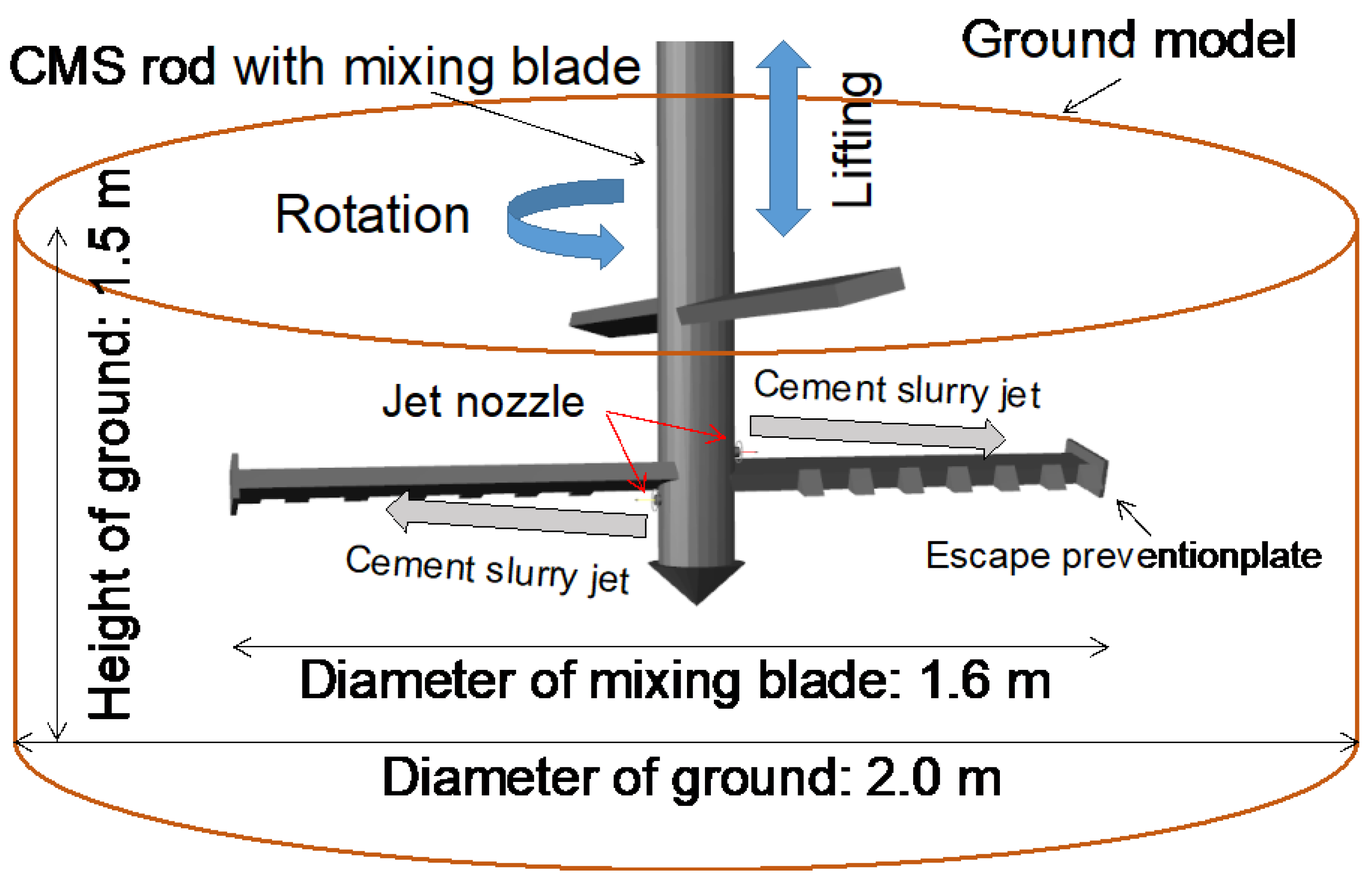
3. Outline of Middle-Pressure Jet Grouting Method

The middle-pressure jet grouting method, which is a cement slurry jet grouting method [9,10,11,12,13,14,15] that uses middle-pressure jets of 20 MPa or less, has been put to practical use as a jet grouting method (QSJ system) [16] and a jet grouting with mechanical agitation and mixing method (CMS system) [17].
The QSJ system is a method using a single-tube type of rod equipped with a jet nozzle, as shown in Figure 1, to loosen the ground by a horizontal water jet during the penetration of the rod. Next, the rod with the jet nozzle is pulled up and rotated, spraying the cement slurry at middle-pressure to develop a columnar soil-improved body with a maximum diameter of f1.0 m [16].
The CMS system is a method using a special mixing blade equipped with an escape prevention plate at the end, as shown in Figure 2, to combine middle-pressure jets of cement slurry with mechanical agitation and mixing in order to achieve mixing efficiency and fluidity of the improved soil [17]. This promotes the discharge of the rising soil, reduces the displacement of the surrounding ground, and enables the development of a high-quality columnar soil-improved body with a maximum diameter of φ 1.6 m [27,28]. The middle-pressure jet grouting method is a ground-improvement method that allows the selection of both of the above-mentioned construction methods, the QSJ system and the CMS system. Up to now, the full-length confirmation of the columnar soil-improved body sampled by boring after full-scale experiments and construction has been performed. Although the quality of the construction method has been verified by unconfined compression tests and so on, it has not been analytically verified. Therefore, in this study, the authors apply the MPS-CAE to the middle-pressure jet grouting method and verify it analytically.

4. Analysis Conditions for MPS-CAE

4.1. Modeling the Analysis Target

The actual scale models shown in Figure 1 and Figure 2 for the jet grouting method (QSJ system) and the jet grouting with mechanical agitation and mixing method (CMS system), respectively, were created as the analytical models by three-dimensional AutoCAD. In the jet grouting method (QSJ system), the jet material was sprayed in one horizontal direction from the jet nozzle in a cylindrical ground with a diameter of 2 m and a height of 1.5 m. In the jet grouting with mechanical agitation and mixing method (CMS system), the mixing blade with a blade diameter of 1.6 m was raised and lowered while injecting the jet material in two directions from the jet nozzles installed above and below the lower blade. An escape prevention plate was attached to the end of the mixing blade, and the slurry was sprayed at an angle to collide with it. As a result, the sprayed cement slurry formed a shape such that it could not easily extend beyond the mixing blade diameter [17].
Table 1 shows the construction specifications for each case of analysis. Cases 1 to 4 are analysis cases that reproduce the jet grouting method (QSJ system). In these cases, the jet flow pressure immediately after the jet is in the water and under the ground was analyzed for each jet pressure and jet material. Case 5 is a reproduction of the jet grouting method (QSJ system), with water cutting during the penetration and slurry spraying from the jets during the pulling up of the rod. Cases 6 and 7 are models of the jet grouting with mechanical agitation and mixing method (CMS system). Focusing on the difference in jet pressure, these cases are set with a middle-pressure jet of 15.0 MPa and a low-pressure of 0.01 MPa, respectively, with the other conditions being the same. After reproducing the jet amount and jet speed, the initial particle distance was set to 0.03 m to reduce the calculation load, and the cement slurry particles were jetted intermittently from the jet nozzle.

4.2. Material Parameters

Table 2 shows the material parameters of the water, cement slurry, and ground particles that comprised the target materials of the analysis. The water particles used the general value of a Newtonian fluid, and the cement slurry particles used the value of a Bingham fluid with the plastic viscosity being measured by a B-type viscometer. For the ground particles, the material parameters were set using the value of a Bingham fluid by a reproducible analysis of an unconfined compression test [29,30]. Bingham fluid has a property whereby it begins to flow when the shear stress exceeds the yield stress. Therefore, until the shear stress exceeds the yield stress value, it is regarded as being in an immobile state, the strain ratio is 0, and an analysis becomes impossible. In this study, as a coping method, a bi-viscosity model [31] is adopted; it treats the fluid as a highly viscous fluid when it is less than the yield stress value. The constitutive equations when flowing and when immobile are expressed by Equations (3) and (4), respectively:
τ i j = P δ i j + 2 ( η p + τ y Π ) ε i j ˙ ν p   Π Π c
τ i j = P δ i j + 2 ( η p + τ y Π c ) ε i j ˙ ν   Π < Π c
where P is the pressure, η p is the plastic viscosity, τ y is the yield value, ε i j ˙ ν p is the strain ratio when flowing, ε i j ˙ ν is the strain ratio when immobile, and Πc is the yield reference value for the fluid state and the immobile state. It should be noted that Πc is expressed by Equations (5) and (6), respectively, using the flow limit strain rate:
Π = 2 ε i j ˙ ε i j ˙
Π c = ( 2 π c ) 2
where π c is the flow limit strain ratio.

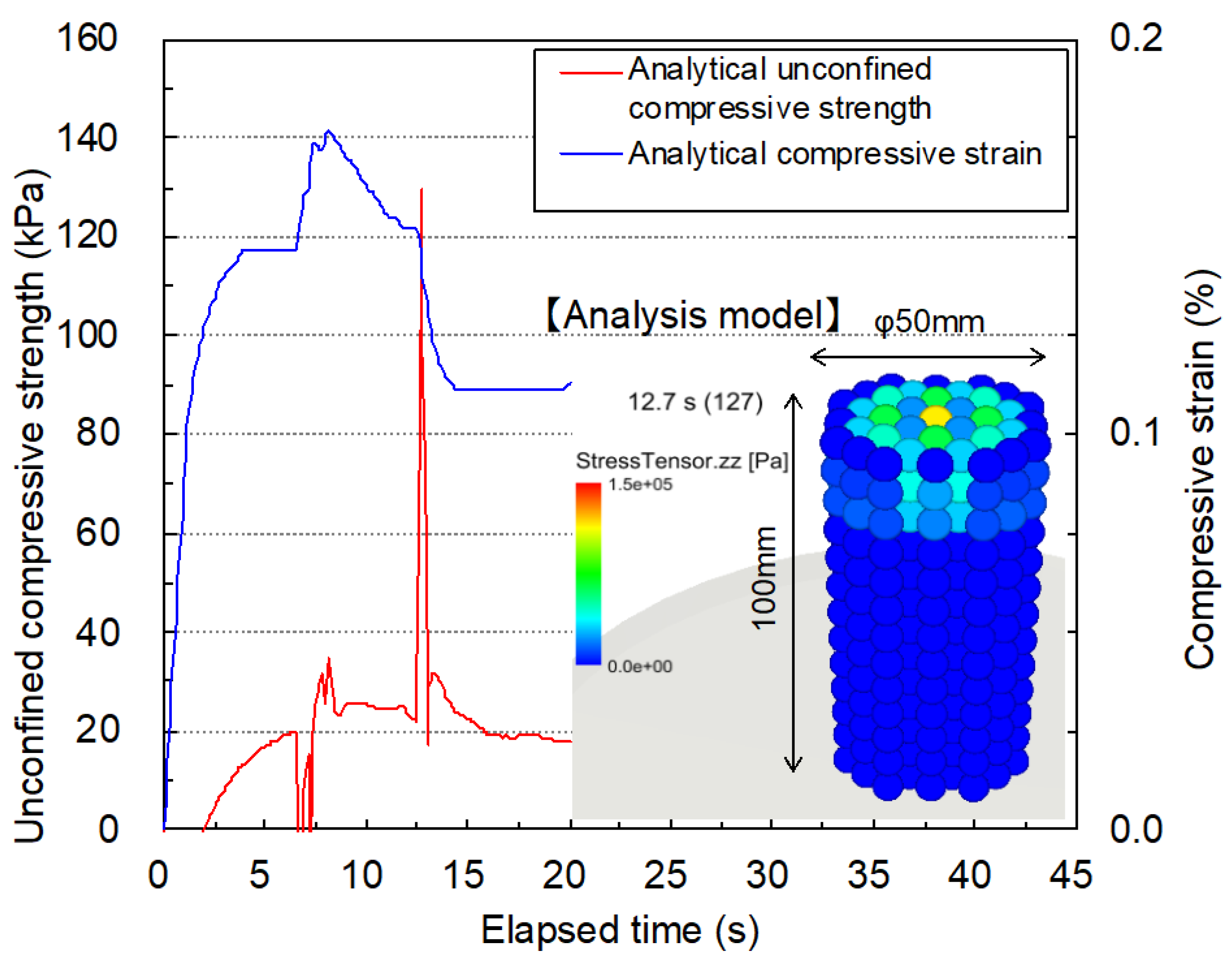
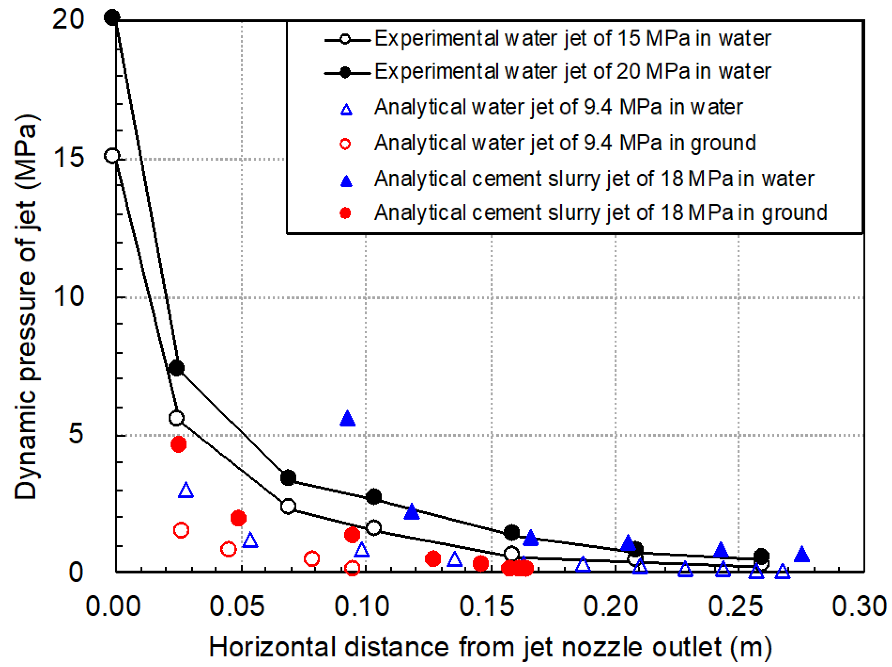
4.3. Validation of Analytical Model

Figure 3 shows the results of the reproducible analysis of the unconfined compression test conducted to confirm the mechanical properties of the ground model used for the analysis. The analytical model in the figure is a bird’s-eye view of the specimen. The plate was lowered from the top at a strain ratio of 1%/min. The graph shows the changes over time in the compressive stress and compressive strain of the upper surface particles of the specimen. The quality of the target soil in this analysis is assumed to be a soft and viscous ground that requires ground improvement when constructing embankments and structures. The unconfined compressive strength of the soil to be analyzed is estimated to be about 20 kPa because the compressive stress by the reproducible analysis yielded 20 kPa after 6.6 s and the compressive strain increased immediately after yielding. However, the compressive stress after yielding shows a maximum value of 129 kPa after 12.7 s after it repeatedly rises and descends as the loading progresses. In actual unconfined compression tests on soil, the compressive stress is greatly reduced by the fracture of the specimen after the yield value reaches the unconfined compressive strength. In this study, the behavior is thought to be different from the actual behavior because the ground particles are assumed to be Bingham fluid.
Figure 4 shows the relationship between the injection distance and the jet flow pressure in Cases 1 to 4 of this analysis. These are the results of the analysis for different space materials, jet materials, and jet pressures. The dynamic pressure of the jet was calculated using Equation (7) using the jet velocity at the tip of the jetted particle group:
P = ( ρ × v 2 ) / 2
where P is the dynamic pressure, ρ is the density of the jetted material, and v is the jet velocity.
The analytical model was verified by comparing it with the experimental results when water was sprayed into the water [32,33]. According to the analysis results of the water jet and the cement slurry jet in water, the dynamic pressure of the jet in both cases decreases with an increase in the jet distance. It can be confirmed that the cement slurry jet, which has a higher jet pressure and a higher jet speed than the water jet, maintains the dynamic pressure farther than the water jet. When the jet pressure is similar, comparing the experimental value of the water jet of 20 MPa in water and the analytical value of the cement slurry jet of 18 MPa in water shows a similar tendency. Furthermore, in the underground, the jet reach and dynamic pressure are lower than in water. Considering these verification results, CAE based on this analysis model was applied in the performance design and evaluation of the middle-pressure jet grouting method.

5. CAE Analysis Results and Discussions

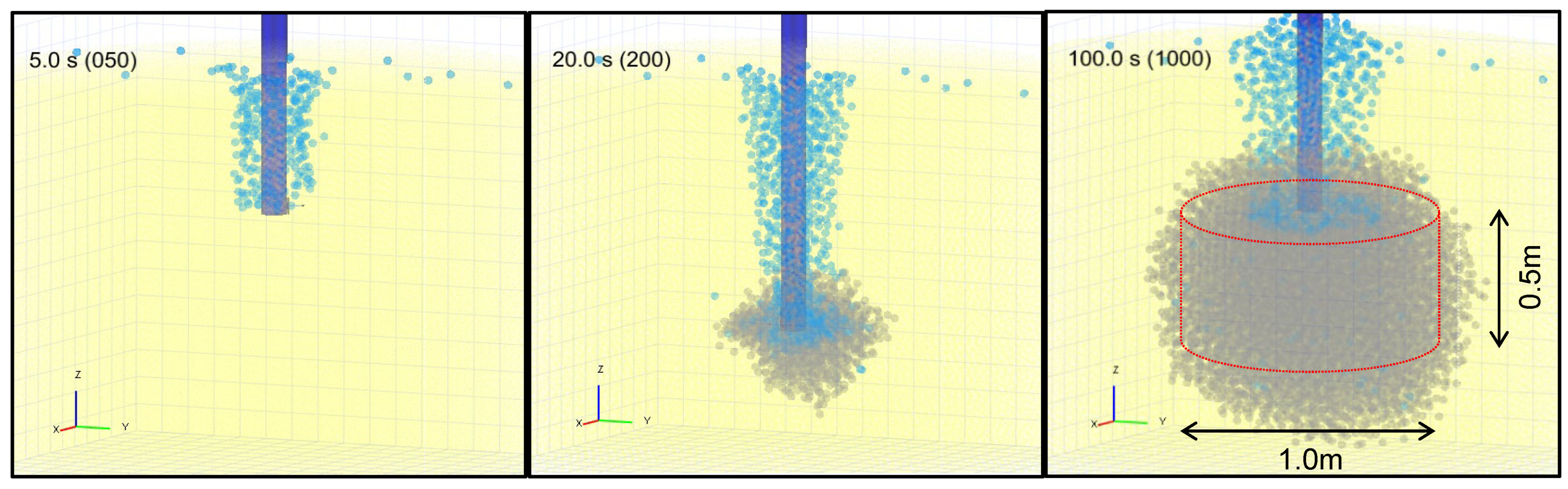
5.1. Reproduction of Development Situation of Columnar Soil-Improved Body by Jet Grouting Method

Figure 5 shows the time-series changes in the development status of the columnar soil-improved body by Case 5 to which the jet grouting method (QSJ system) was applied. Ground particles are shown in semi-transparent yellow, water particles in light blue, and slurry particles in gray. The figure reproduces the construction process in which water is sprayed, while rotating and penetrating the rod with the jet nozzle, to a depth of 1.0 m in 10 s after the start of construction. Then the rod is rotated and pulled up to enable the spraying of the cement slurry to a depth of 0.5 m in 90 s. As the pulling-up speed is slower than the penetration speed, the pressure of the cement slurry jet is higher than that of the water jet, and the jet amount is large, it can be confirmed that the ground cutting distance by the cement slurry jet when the rod is pulled up is large. In addition, although it has not been possible to reproduce exactly how the mixture of water, cement slurry, and soil generated at a real site is discharged as sludge through the rod, the water particles were sprayed at the time of the initial water jet into the surrounding ground particles. After the collision, it was confirmed that the particles were discharged to the upper part.
The columnar soil-improved body, with a diameter slightly smaller than the improvement range of 1.0 m in diameter shown in the figure, was developed 100 s after the completion of the construction. The diameter (Φ) of the design improvement at a real site, based on this construction specification, is Φ0.8 m for cohesive soil with adhesive force of c = 10 kPa and Φ1.0 m for cohesive soil with adhesive force of c = 5 kPa (Komaki et al. 2018a). This is the adhesive strength, c = qu/2 = 10 kPa, when it is estimated from the yield value of qu = 20 kPa at the initial stage of loading from the results of the unconfined compression test shown in Figure 3. In addition, the adhesive strength of 10 kPa agrees with the diameter of Φ0.8 m–1.0 m of the improved body actually developed at the site. It corresponds to approximately 1.0 m. It can be said that this generally reproduces the finished form of the columnar soil-improved body according to the construction specifications and depending on the ground conditions. However, the discharge of sludge containing ground particles generated during the development process of the columnar soil-improved body has not been reproduced. This is an issue in modeling the ground, as seen in the behavior after yielding in the reproducible analysis of the unconfined compression test on the soil.

5.2. Reproduction of Development Situation of Columnar Soil-Improved Body by Jet Grouting with Mechanical Agitation and Mixing Method

Figure 6 and Figure 7 show the conditions of the development of the columnar soil-improved body in Case 6 (middle-pressure jet: 15.0 MPa) and Case 7 (low-pressure jet: 0.01 MPa) using the jet grouting with mechanical agitation and mixing method (CMS system) with different jet pressures, respectively. Six seconds after the start of construction, the injection nozzle reached the top of the planned columnar soil-improved body, and that was the time when the cement slurry jet was just started. After 48 s, the maximum depth was penetrated, and after 78 s, the jet nozzle was pulled up to the top of the planned columnar soil-improved body again, that is, the development was completed. The cement slurry jet reached the escape prevention plate at the tip of the mixing blade six seconds after the start of construction by the middle-pressure jet (15.0 MPa), but not by the low-pressure jet (0.01 MPa). Furthermore, in the vicinity of the outer periphery of the improved diameter at the maximum depth penetration and at the completion of the development, the middle-pressure jet was more densely packed with cement slurry particles than the low-pressure jet. In the case of the low-pressure jet, the cement slurry particles were concentrated in the center of the mixing blade and pushed downwards outside the mixing blade. As a result, the amount of cement slurry sprayed into the planned improvement range decreased, and the required amount of cement slurry could not be not sprayed by the low-pressure jet.

5.3. Performance Evaluation of Jet Grouting with Mechanical Agitation and Mixing Method

Figure 8 shows the changes over time in the amount of sprayed cement slurry within the planned improvement length of 0.5 m and the improvement diameter of 1.6 m. The planned jet amount in the figure is consistent with the volume of all cement slurry particles sprayed from the jet nozzle, and the planned jet amount in the 0.1 m section is 1/5 of the total amount. From Figure 8, the jet of cement slurry was started three seconds after the start of construction, and the sprayed amount within the planned range increased with the passage of time. 78 s after the development was completed, about 90% of the planned amount of cement slurry was filled in the improvement range at middle-pressure jet (15.0 MPa), and the planned value was exceeded at the central depth. On the other hand, although the trend of the increase was similar, for the low-pressure jet (0.01 MPa), it was only about 60% of the planned jet amount, and the planned value could not be secured even at the central depth.
Based on the analysis results at the central depth of 0.1 m in the planned improvement area, the area was divided into toroidal shapes every 0.1 m in the radial direction from the central axis of the columnar soil-improved body, the number of particles in the ground and the cement slurry was measured, and the cement slurry for all the particles in the area was measured. The cement slurry jet ratio was calculated from the volume fraction of particles. The horizontal distribution is shown in Figure 9. Comparing the middle-pressure jet (15.0 MPa) and the low-pressure jet (0.01 MPa), the middle-pressure jet had a higher cement slurry jet ratio near the outer periphery of the mixing blade, and the cement slurry jet ratio was higher throughout the improvement range when the development was completed in 78 s. This is because it was possible to increase the jet ratio of the cement slurry near the outer periphery of the mixing blade by using the middle-pressure jet, and the jet of the cement slurry was surely sprayed into the improved range, resulting in the development of high quality columnar soil-improved body.

6. Conclusions

In this study, the authors focused on the middle-pressure jet grouting method, which has a complicated development mechanism for the columnar soil-improved body, with the aim of establishing a system of computer-aided engineering (CAE) that simulates the performance of the method on a computer. The improvement process was reproduced by MPS, which is one of the solutions in CAE. It is capable of handling ground failure phenomena and high-velocity fluids. The construction specifications were examined according to the ground conditions. Furthermore, in order to confirm the effect of using middle-pressure jet grouting with mechanical agitation and mixing, a comparative analysis was performed with different jet pressures, the development situation was visualized, and the performance of the method was evaluated.
The obtained results can be summarized as follows:
(1)
The mechanical properties of the ground model were estimated by a reconstructive analysis of unconfined compression tests on soil.
(2)
The jet behavior of the water and the cement slurry model was verified by a jet analysis of a stationary fluid.
(3)
The final shape of the columnar soil-improved body, obtained by a reproduction analysis of the jet grouting method, was about the same as the design improvement diameter at an actual site.
(4)
Modeling of the ground particles is one of the reasons why the sludge discharge situation by the jet grouting method cannot be reproduced.
(5)
In the reproduction analysis of the jet grouting with mechanical agitation and mixing method, by using the middle-pressure jet grouting together with the mechanical agitation and mixing method, the cement slurry jet ratio in the planned improvement range, including the periphery of the mixing blade, was increased and a high quality columnar soil-improved body was obtained.
(6)
It is expected that the introduction of CAE will contribute to the visualization of the ground, and it is suggested that CAE be used as an effective tool for the visual management of ground-improvement construction and the maintenance of improved grounds in the life cycle.
It will be imperative to link the results to the ground improvement practice and tell to what extend the results of this simulation can improved the practice. There is still a gap between the conclusions and the obtained results, an in-depth analysis should be provided.
The middle-pressure jet grouting method is one of the effective ground-improvement methods. However, its design and construction often rely on conventional empirical rules, mainly before construction, during construction, and after construction. This is because it is difficult to see the inside of the ground. It is thought, therefore, that CAE-based design and performance evaluations will play an important role in improving the reliability and economic efficiency of ground-improvement methods, not only for the middle-pressure jet grouting method, but also for the ground-improvement technology in general. Although the introduction of CAE to ground-improvement methods is via a computer, it is expected that it will contribute to the visualization of the ground. In the future, CAE will be an effective tool for the visual management of ground-improvement construction and the maintenance of improved grounds in the life cycle of the ground-improvement method.

Author Contributions

Conceptualization, S.I.; methodology, S.I.; software, S.S. and T.K.; validation, S.S., T.K. and Y.N.; formal analysis, S.S. and T.K.; investigation, Y.N.; resources, T.K. and Y.N.; data curation, S.I. and S.S.; writing—original draft preparation, S.I.; writing—review and editing, S.I.; visualization, S.I. and T.K.; supervision, S.I.; project administration, S.I.; funding acquisition, S.I. All authors have read and agreed to the published version of the manuscript.

Funding

This research received no external funding.

Institutional Review Board Statement

Not applicable.

Informed Consent Statement

Not applicable.

Data Availability Statement

Not applicable.

Conflicts of Interest

The authors declare no conflict of interest.

References

  1. Atangana Njock, P.G.; Chen, J.; Modoni, G.; Arulrajah, A.; Kim, Y.H. A review of jet grouting practice and development. Arab. J. Geosci. 2018, 11, 459. [Google Scholar] [CrossRef]
  2. Atangana Njock, P.G.; Shen, J.S.; Modoni, G.; Arulrajah, A. Recent Advances in Horizontal Jet Grouting (HJG): An Overview. Arab. J. Sci. Eng. 2018, 43, 1543–1560. [Google Scholar] [CrossRef]
  3. Modoni, G.; Croce, P.; Mongiovì, L. Theoretical modelling of jet grouting. Géotechnique 2016, 56, 335–347. [Google Scholar] [CrossRef]
  4. Modoni, G.; Wanik, L.; Giovinco, G.; Bzówka, J.; Leopardi, A. Numerical analysis of submerged flows for jet grouting. Proc. Inst. Civ. Eng. Ground Improv. 2016, 169, 42–53. [Google Scholar] [CrossRef] [Green Version]
  5. Nakanishi, W.; Nakazawa, J. The process of development on jet grouting methods and their future. Soil Mech. Found. Eng. 2006, 54, 10–12. [Google Scholar]
  6. Pinto, A.; Falcão, J.; Pinto, F.; Melo Ribeiro, J. Ground improvement solutions using jet grouting columns. In Proceedings of the 16th International Conference on Soil Mechanics and Geotechnical Engineering, Osaka, Japan, 12–16 September 2005; pp. 1249–1252. [Google Scholar]
  7. Shen, S.L.; Njock, P.G.A.; Zhou, A.; Lyu, H.M. Dynamic prediction of jet grouted column diameter in soft soil using Bi-LSTM deep learning. Acta Geotech. 2012, 16, 303–315. [Google Scholar] [CrossRef]
  8. Shen, S.L.; Wang, Z.F.; Yang, J.; Ho, C.E. Generalized approach for prediction of jet grout column diameter. J. Geotech. Geoenviron. Eng. 2013, 139. [Google Scholar] [CrossRef]
  9. Burke, G.K. Jet Grouting Systems: Advantages and Disadvantages. In GeoSupport 2004: Drilled Shafts, Micropiling, Deep Mixing, Remedial Methods, and Specialty Foundation Systems; Turner, J.P., Mayne, P.W., Eds.; American Society of Civil Engineers: Reston, VA, USA, 2004. [Google Scholar]
  10. Harada, K.; Ohbayashi, J.; Matsumoto, J.; Kubo, Y.; Akima, T. New ground improvement technologies under restricted conditions in Japan. Jpn. Geotech. Soc. Spec. Publ. 2015, 2, 1165–1170. [Google Scholar] [CrossRef] [Green Version]
  11. Pinto, A.; Tomásio, R.; Marques, G. Ground improvement with jet grouting solutions at the new cruise terminal in Lisbon, Portugal. Procedia Eng. 2016, 143, 1495–1502. [Google Scholar] [CrossRef] [Green Version]
  12. Wang, Z.F.; Bian, X.; Wang, Y.Q. Numerical approach to predict ground displacement caused by installing a horizontal jet grout column. Mar. Georesour. Geotechnol. 2017, 35, 970–977. [Google Scholar] [CrossRef]
  13. Wang, Y.; Li, L.; Li, J.; Sun, D. Jet-grouting in ground improvement and rotary grouting pile installation: Theoretical analysis. Geomech. Eng. 2020, 21, 279–288. [Google Scholar]
  14. Zhang, W.; Li, Y.; Goh, A.; Zhang, R. Numerical study of the performance of jet grout piles for braced excavations in soft clay. Comput. Geotech. 2020, 124, 103631. [Google Scholar] [CrossRef]
  15. Zhang, W.; Hong, L.; Yongqin, L.; Zhang, R.; Goh, A.T.C. Assessment of effect of jet grouting slabs on responses for deep braced excavations. Undergr. Space 2021, 6, 185–194. [Google Scholar] [CrossRef]
  16. Komaki, T.; Fukada, S.; Shimano, A.; Nakanishi, Y. Efficient of Mechanical mixing method with middle pressure injection by High performance fluidizing agent. In Proceedings of the 13th National Symposium on Ground Improvement, Kyoto, Japan, 24–26 October 2018; pp. 375–378. [Google Scholar]
  17. Komaki, T.; Fukada, S.; Sumi, K.; Nakanishi, Y.; Tanaka, N. Demonstration experiment of evolution technology by combination mixing slurry of middle pressure injection total system. In Proceedings of the 53th Japan National Conference on Geotechnical Engineering, Takamatsu, Japan, 24–26 July 2018; pp. 835–836. [Google Scholar]
  18. Hattori, M. An attempt to apply mathematical foundation of Moving Particle Simulation to the MPS software “Particleworks”. Proc. Symp. Educ. Appl. Inf. Technol. 2015, 9, 59–62. [Google Scholar]
  19. Shakibaeini, A.; Jin, Y.C. MPS mesh-free particle method for multiphase flows. Comput. Methods Appl. Mech. Eng. 2012, 229–232, 13–26. [Google Scholar] [CrossRef]
  20. Tanaka, M.; Cardoso, R.; Bahai, H. Multi-resolution MPS method. J. Comput. Phys. 2018, 359, 106–136. [Google Scholar] [CrossRef]
  21. Chang, K.H. Product Design Modeling Using CAD/CAE: The Computer Aided Engineering Design Series; Elsevier: Amsterdam, The Netherlands, 2014. [Google Scholar]
  22. Hamri, O.; Léon, J.C.; Giannini, F.; Falcidieno, B. Advances in Engineering Software Software environment for CAD/CAE integration. Adv. Eng. Softw. 2010, 41, 1211–1222. [Google Scholar] [CrossRef]
  23. Inazumi, S.; Kuwahara, S.; Jotisankasa, A.; Chaiprakaikeow, S. MPS-CAE simulation on dynamic interaction between steel casing and existing pile when pulling out existing piles, International Journal of GEOMATE: Geotechnique. Constr. Mater. Environ. 2020, 18, 68–73. [Google Scholar]
  24. Pan, Z.; Wang, X.; Teng, R.; Cao, X. Computer-aided design-while-engineering technology in top-down modeling of mechanical product. Comput. Ind. 2016, 75, 151–161. [Google Scholar] [CrossRef]
  25. Yang, P.; Zang, M.; Zeng, H. DEM-FEM simulation of tire-sand interaction based on improved contact model. Comput. Part. Mech. 2020, 7, 629–643. [Google Scholar] [CrossRef]
  26. Inazumi, S.; Komaki, T.; Nakanishi, Y.; Hashida, H.; Suzuki, M. Qualities evaluation on high pressure Jet mixing ground improvement methods by distinct element method (DEM). In Proceedings of the 13th National Symposium on Ground Improvement, Kyoto, Japan, 24–26 October 2018; pp. 211–216. [Google Scholar]
  27. Shimano, A.; Yamazaki, J.; Shinsaka, T. The study about work progress control of jet grouting method. In Proceedings of the 12th National Symposium on Ground Improvement, Okayama, Japan, 12 September 2016; pp. 455–458. [Google Scholar]
  28. Shinsaka, T.; Yamazaki, J.; Nakanishi, Y.; Komiya, K. Quality control and shape control techniques in jet grouting. In IFCEE 2018: Innovations in Ground Improvement for Soils, Pavements, and Subgrades; Stuedlein, A.W., Lemnitzer, A., Suleiman, M.T., Eds.; American Society of Civil Engineers: Reston, VA, USA, 2018. [Google Scholar]
  29. Güllü, H. A new prediction method to rheological behavior of grout with bottom ash for jet grouting columns. Soils Found. 2017, 57, 384–396. [Google Scholar] [CrossRef]
  30. Güllü, H.; Cevik, A.; Al-Ezzi, K.M.; Gülsan, M.E. On the rheology of using geopolymer for grouting: A comparative study with cement-based grout included fly ash and cold bonded fly ash. Constr. Build. Mater. 2019, 196, 594–610. [Google Scholar] [CrossRef]
  31. Kamalova, Z.; Hatanaka, S. Moving particle simulation for a simplified permeability model of pervious concrete. Comput. Concr. 2019, 24, 571–578. [Google Scholar]
  32. Croce, P.; Flora, A. Analysis of single-fluid jet grouting. Géotechnique 2000, 50, 739–748. [Google Scholar] [CrossRef]
  33. Croce, P.; Flora, A.; Modoni, G. Jet Grouting: Technology, Design and Control; CRC Press: Boca Raton, FL, USA, 2014. [Google Scholar]
Figure 1. Conceptual demonstrations of jet grouting method.
Geosciences 11 00313 g001
Figure 2. Conceptual demonstrations of jet grouting with mechanical agitation and mixing method.
Geosciences 11 00313 g002
Figure 3. Reproduction of unconfined compression test for soil.
Geosciences 11 00313 g003
Figure 4. Relationship between jet distance and jet flow pressure.
Geosciences 11 00313 g004
Figure 5. Conditions of development of columnar soil-improved body by jet grouting type method.
Geosciences 11 00313 g005
Figure 6. Conditions of development of columnar soil improved body by jet grouting with mechanical agitation and mixing method (jet pressure: 15.0 MPa).
Geosciences 11 00313 g006
Figure 7. Conditions of development of columnar soil improved body by jet grouting with mechanical agitation and mixing method (jet pressure: 0.01 MPa).
Geosciences 11 00313 g007
Figure 8. Time-dependent change in amount of cement slurry jet in plan improvement range.
Geosciences 11 00313 g008
Figure 9. Horizontal distribution of cement slurry jet ratio.
Geosciences 11 00313 g009
Table 1. Construction specifications.
Case of AnalysisCase 1Case 2Case 3Case 4Case 5Case 6Case 7
Method of constructionQSJQSJQSJQSJQSJCMSCMS
Range of target WaterWaterGroundGroundGroundGroundGround
Material of jetWaterCement slurryWaterCement slurryWater *1Cement slurry *2Cement slurryCement slurry
Length of penetration while blanking (m)0.50.50.50.50.50.50.50.5
Length of penetration while improving soil (m)----0.50.50.50.5
Amount of jet (L/min)80908090809080 × 280 × 2
Pressure of jet (MPa)9.418.09.418.09.418.015.00.01
Velocity of jet (m/s)137.5155.0137.5155.0137.5155.0141.54.2
Velocity of penetration while blanking (m/min)----6.0-10.010.0
Velocity of penetration while improving soil (m/min)----6.0-0.670.67
Velocity of lifting while improving soil (m/min)-----0.331.01.0
Velocity of rotation (rpm)----80202020
*1 while penetrating. *2 while pulling up.
Table 2. Material parameters.
Range of TargetDensity
(kg/m3)
W/C
(-)
Yield Value
(Pa)
Plastic Viscosity
(Pa·s)
Yield Point
(-)
Fluid Model
Water1000----Newtonian fluid
Cement slurry15001.0100.280.0001Bingham fluid
Ground1600-1,000,00010000.0001Bingham fluid
Publisher’s Note: MDPI stays neutral with regard to jurisdictional claims in published maps and institutional affiliations.

