Article

Electrical Properties and Anisotropy of Schists and Fault Rocks from New Zealand’s Southern Alps under Confining Pressure

1
Institute of Geosciences, Johannes Gutenberg University, Johann-Joachim-Becher-Weg 21, 55128 Mainz, Germany
2
Department of Geology, University of Otago, P.O. Box 56, Dunedin 9054, New Zealand
3
U.S. Geological Survey, Earthquake Science Center, US Geological Survey, 345 Middlefield Rd MS977, Menlo Park, CA 94025, USA
*
Author to whom correspondence should be addressed.
Geosciences 2022, 12(3), 121; https://doi.org/10.3390/geosciences12030121
Submission received: 24 October 2021 / Revised: 24 February 2022 / Accepted: 28 February 2022 / Published: 4 March 2022
(This article belongs to the Special Issue Microstructural Analyses of Fault Rocks)

Abstract

:
Magnetotelluric models spanning the Pacific–Australian Plate boundary in New Zealand’s South Island indicate a localized zone of low electrical resistivity that is spatially coincident with the ductile mid-crustal part of the Alpine Fault Zone (AFZ). We explored the source of this anomaly by measuring the electrical properties of samples collected from surface outcrops approaching the AFZ that have accommodated a gradient of systematic strain and deformation conditions. We investigated the effects of tectonite fabric, fluid saturated pore/fracture networks and surface conductivity on the bulk electrical response and the anisotropy of resistivity measured under increasing confining pressures up to 200 MPa. We find that porosity and resistivity increase while porosity and the change in anisotropy of resistivity with confining pressure (δ (ρ)/δ (peff)) decreases approaching the AFZ, indicating the electrical response is controlled by pore fluid conductivity and modified during progressive metamorphism. Conversely, Alpine mylonites exhibit relatively low resistivities at low porosities, and lower δ (ρ)/δ (peff) than the schists. These findings indicate a transition in both the porosity distribution and electrical charge transport processes in rocks that have experienced progressive grain size reduction and mixing of phases during development of mylonitic fabrics due to creep shear strain within the AFZ.

1. Introduction

Around the globe there are numerous regions of mid- to lower continental crust that exhibit particularly high conductivities on the order of 0.01–1.0 S·m−1 [1,2] The electrical properties of these regions tend to vary laterally [3,4,5] and they sometimes exhibit anisotropy [6,7]. Termed “anomalously conductive mid-crust”, such regions are identified by conductivity values at least 100-times higher than those typical of the dry granulite facies rocks that should make up the mid- to lower crust [2]. The anomalously conductive mid-crust commonly coincides with low seismic velocity, reflection anomalies, and low surface heat flow, and is most typical in tectonically active areas such as plate boundaries [8,9]. It has been suggested that these electrical anomalies reflect the presence of high geothermal gradients [10,11], interconnected networks of conductive phases such as fluids [12,13], partial melts [14,15], grain boundary graphite films [4,16,17], or sulphides and magnetites [4,18]. We must determine how a continuous conducting phase network is established and maintained over large distances under mid- to lower crustal conditions in order to understand how these conductive anomalies occur.
The Southern Alps Anomalous Electrical Conductor (SAEC) (Figure 1) is a zone of significantly conductive rock identified in magnetotelluric (MT) models [13,19,20] that is spatially coincident with the ductile-creeping mid-to-lower crustal part of New Zealand’s Alpine Fault Zone (AFZ), an active structure accommodating the majority of relative Pacific–Australian Plate motions in this region. The SAEC also coincides with anomalously reduced seismic velocity, so it is commonly speculated to result from a network of electrolytic fluids, rather than interconnected melts or solid phases [2,13,14,15,16,17,18,19,20].
The SAEC lies within variably metamorphosed accreted marine sediments of the Rakaia and Aspiring subdivisions of the Torlesse Composite terranes [28]. Surface outcrops above the SAEC grade from Otago Semi-Schists in the prehnite—pumpellyite facies 60 km from the fault, to ultramylonite in the K-feldspar—amphibolite facies of the Alpine Schist adjacent to the fault [13,21]. Due to the rapid exhumation rates (up to 10 mm/year) on the Alpine Fault [29], and the rapid erosion rates (9.8 × 10⁷ g/(km2·year)) in the Southern Alps [30], this lateral zoning of metamorphic facies is inferred to be the same as that along a progressive burial trajectory from protolith metasediments to 35 km depth under the highest peaks of the Southern Alps.
Once maximum metamorphic grade is achieved, mylonitic tectonite fabrics progressively strengthen during simple shear below the brittle-creep transition in the mid-crustal parts of the AFZ. Conductivity increases approaching the AFZ in both the brittle and the temperature-sensitive creep (also known as ductile) regimes, but the highly conductive region we refer to as the SAEC lies entirely below the brittle-creep transition.
By analysing a suite of rock samples collected at surface outcrops approaching the AFZ surface trace from the east across the hanging wall (Figure 1C), we have investigated the effects of progressive shear-related properties (microstructures, tectonite fabric and the connectivity of conductive phases, such as electrolyte-bearing fluids in pore/fracture networks and grain boundary surface conductivity) on the electrical responses. Our aim is to determine the factors controlling the gradation, from high resistivity in low-strain schists to low resistivity in high-strain mylonites within the AFZ.
Complex resistivity laboratory measurements of saturated hand samples were made at 23.3 °C, 0.1 M KCl saturating salinity, in various orientations with respect to their tectonite fabrics, and under a range of increasing effective confining pressures representative of the crustal seismogenic zone above the brittle-creep transition. The salinity used was not intended to replicate the in situ electrolytic profile, and therefore comparison with absolute resistivity values is avoided. These measurements reveal trends that suggest the electrical responses of schistose and mylonitized rocks are the products of different processes.

2. Background

2.1. The Alpine Fault Zone

The SAEC was identified by transcontinental MT surveys related to the South Island Geophysical Transect (SIGHT) project. Modelling and inversion of apparent resistivity and phase data for MT surveys [13,31,32] indicate a region with resistivities on the order of 1 < ρ < 300 Ω·m (conductivity range of 3.3 × 10⁻³ to 1 S/m). By comparison, the resistivity of the surrounding rock is greater than 3000 Ω·m [13]. Similar to other mid-crustal conductors, such as the German Continental Deep Drilling Program (KTB) [33], the Himalaya of central Nepal [34], and the Itoigawa-Shizuoka tectonic line in central Japan [35], the SAEC is associated with anomalously reduced seismic velocity, a plate boundary setting and deeply circulating fluids. However, doubts concerning deep crustal fluid residence time [36], wetting angle-related connected pore networks [2,37] and petrological support for a dry, dense lower crust [38] have led to speculation of additional conductive processes to supplement the effects of deep fluids as the sole source of mid-crustal conductors. Regardless of the specific source of the SAEC, elements that contribute to high electrical conductivity such as rapid uplift of hanging wall rocks [39], a steep geothermal gradient [40] and the presence and electrolyte compositions of fluids [22] are related to the convergent nature of the plate boundary that manifests as the Alpine Fault. This obliquely convergent NE-SW oriented strike-slip structure accommodates 70–80% of the strain accumulating at the transform boundary between the Australian and Pacific Plates [41]. The remaining strain is distributed onto structures outcropping east of the fault trace over a zone 100 to 200 km wide [41,42,43,44].
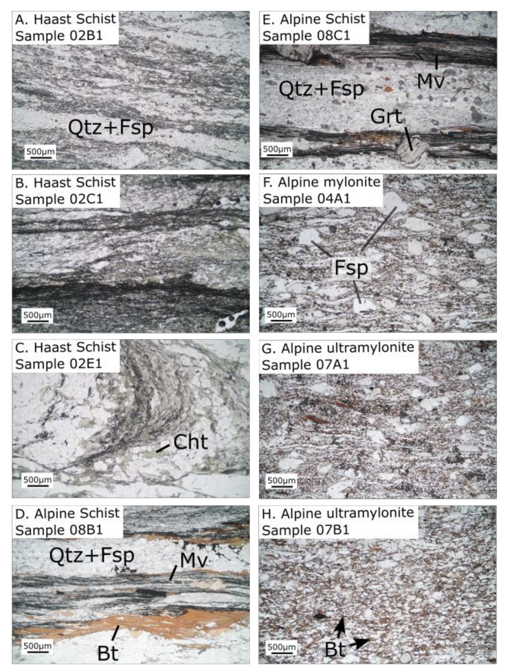
Metamorphic units are graded from metasediments on the eastern side of the South Island to greenschist facies (chlorite, then biotite-bearing), and finally lower amphibolite facies (garnet-oligoclase-bearing) Alpine Schist nearest the AFZ [44]. At approximately 60 km from the Alpine Fault, the planar foliation and mineral layering typical of the Haast Schist develops in the metasediments. This fabric intensifies further into typical Alpine Schist 15 km from the fault, with quartz and feldspar microlithons and phyllosilicate-rich foliation domains. Starting about 1 km from the fault, the schistose fabric is further overprinted by a mylonitic fabric, which forms at mid-crustal depths by temperature-sensitive (dislocation and grain size sensitive) creep mechanisms [45]. Mylonitization of Alpine Schist results in grain size reduction, mixing of phases, and the destruction of the planar schistose foliation (e.g., Figure 2A–E). These Alpine mylonites and ultramylonites tend to have more phase boundaries (boundaries between different minerals) than grain boundaries (between the same minerals) because of this transition in tectonite fabric (Figure 2F–H).
The Alpine Fault Drilling Project Phase 2 (DFDP-2) borehole [45,46,47] sampled the typical Alpine Fault hanging wall stratigraphic column comprising Quaternary sediments from the surface to 239 m, Alpine Schist to 280 m, protomylonite to 852 m and mylonite to 893 m. At the surface, protomylonites are first observed approximately 1 km southeast of the Alpine Fault’s active surface trace. To the southwest, these transition to mylonites at ~0.5 km from the fault core, ultramylonites at ~0.1 km and finally cataclasite at <50 m [21,40,47]. These fault rocks have been exhumed along the fault ramp from as much as 35 km depth due to convergence along this plate boundary [21,39,43,48,49]. Erosion and a rapid uplift of 10 mm/year have exposed a near continuous mid- to upper-crustal section across the Southern Alps, where concentric age contours define a local age minimum indistinguishable from 0 Ma centred around Franz Josef Glacier [39]. In the brittle regime, fluids circulate primarily through planar fracture networks that become less connected with depth, resulting in extreme temperature and fluid pressure variations adjacent to the Alpine Fault. An examination of the high-resolution acoustic borehole televiewer (BHTV) logs acquired in the DFDP-2B borehole found planar features that may be fractures or foliation to have an average density of 3.6 m−1 and a maximum of density 7.2 m−1 between 620 and 660 m depth [50]. The features inferred to make the greatest contributions to permeability (k) are a suite of planar fractures that occur primarily between 260 and 545 m in the hanging wall.
Below the brittle-creep transition, macroscopic fractures are unlikely to persist within a rock mass rapidly deforming by continuous creep. Thus, fluid migration is controlled by smaller-scale interconnected porosity, such as microfractures or grain boundary pores [51]. Although the connections between pores may also be destroyed by creep or collapse under the high confining pressures at mid-crustal depths [37], these pores may also be connected due to shear zone dynamic processes [51,52]. Grain boundary “etch pit” pores created by dislocation enhanced dissolution from reactive metamorphic fluids that have been identified in Alpine mylonites [51] may communicate fluids during deformation and enhance permeability [52]. However, it is improbable that this process has a significant effect on permeability in the crustal seismogenic depth range comparable to the conditions that were explored in this study.

2.2. Electrical Current Transport in Rocks and Pore Fluids

For silicate crustal rocks, electric current is primarily transported in two ways: 1. through ionic transport in electrolytic fluids communicating through pore space and fractures, and 2. by “surface conductivity” along the electrical double layer (EDL) [53,54,55]. In porous rocks, these networks are composed of an interconnected, fluid saturated pore system that allows multiple conductive mechanisms to operate in parallel for a given cross-section [56]. Complex conductivity (σ*), given in Equation (1), is the sum of in-phase conductivity (σ′) and quadrature conductivity (σ″). Complex conductivity and complex resistivity (ρ*) are inversely related to one another, as shown in Equation (2).
σ* = σ′ + i σ″
σ* = 1/(ρ*)
The in-phase component of conductivity (σ′) is controlled by the ratio of fluid conductivity (σf) and the formation factor (F), and by surface conductivity (σs) along the EDL on grain or phase boundaries. The formation factor (F) is also found by the porosity (Φ) raised to the cementation exponent (m) [57].
F = σf/σ′ = Φ−m
Pore fluid conduction is dependent on dissociation effects from both salts (electrolytes) and other total dissolved solids (TDS). The type of electrolyte, the electrolyte concentration, the pore network geometry and the temperature all control pore fluid conductivity by affecting migration of charged ions through solution. Surface conductivity, a function of mineral and grain surface roughness [56], is a process where sorbed ions migrate along the mineral grain–water interface in the EDL and is most significant in rocks with minerals with high cation exchange capacity (CEC) (e.g., clays, phyllosilicates).
A simplified model of charge transported in fluid and on surfaces in parallel, in a given cross-section of rock, is provided in Figure 3.

2.3. Anisotropy of Electrical Properties and the Effect of Effective Confining Pressure

Charge transport is related to the geometry and spatial arrangement of pore networks and grain/phase boundaries. Consequently, the anisotropy of rock fabric influences the anisotropy of resistivity [58,59,60]. Because of this relation, changes in shear-strain or effective confining pressure (peff) have measurable effects on electrical properties [61]. As previously noted, Alpine Schist has highly anisotropic fabrics which manifest as a strong planar foliation of alternating micaceous and quartzofeldspathic domains. This planar foliation is reduced by mylonitization and mixing of phases approaching the AFZ [45,47,62]. The porosity of these Alpine mylonites comprises approximately equant etch pits and open crack-like compliant voids that are related to thermal contraction during exhumation [50,62,63,64]. Closure of exhumation cracks with increasing confining pressure can change the anisotropy of permeability by altering the preferred flow paths. This replicates the anisotropic behaviour of the rocks under in situ conditions, with an overall decrease in permeability generally described by a power function [59,60]. Since resistivity obeys a similar function to permeability under confining pressure [59], resistivity measurements should be made as close to in situ conditions as possible.

3. Materials and Methods

3.1. Sample Collection and Preparation

Samples were gathered from AFZ Mylonite, Haast and Alpine Schist outcrops located above the SAEC. Locations were selected to determine how systematic changes in mineralogy and tectonite fabrics vary across metamorphic and strain gradients approaching the Alpine Fault through the hanging wall. Samples were cut into approximately 2 cm cubes and sample dimensions were measured and used to calculate sample volume, V. Unconfined porosity, ϕ, was determined using a submersion method. Samples were dried in a vacuum oven and weighed to obtain dry mass, md. Samples were then evacuated for three days and saturated with DI water while still under vacuum. They were weighed again while submerged in DI water to obtain submerged weight ms. Since volume of mineral grains is (1 − ρ)V, buoyancy due to the displaced water during submersion requires
ms = md − (1 − ϕ) Vρw
where ρw is density of water. Rearranging terms gives the fraction of connected void space
ϕ = 1 − (md − ms)/Vρw
Unconfined porosity, using Equation (5), is listed in Table 1.
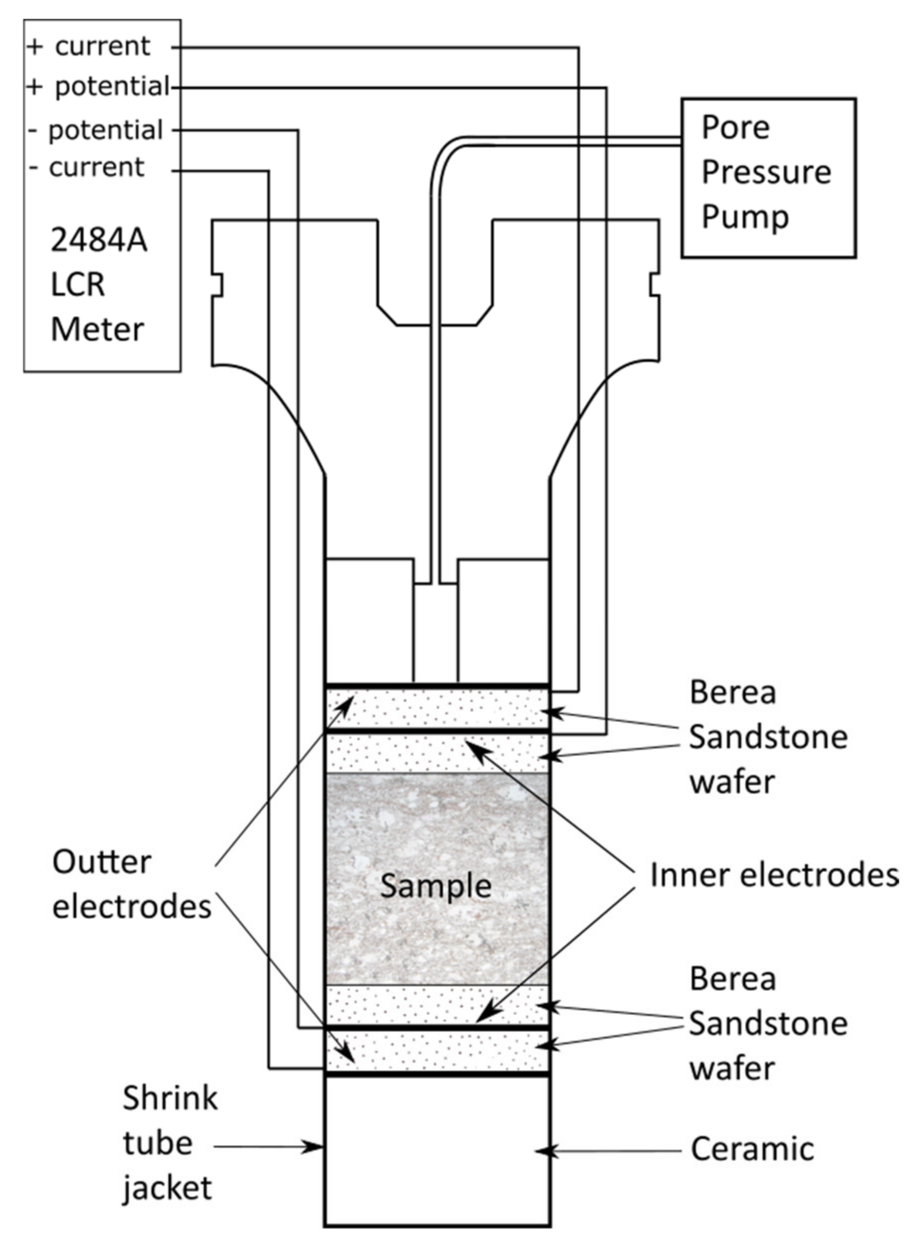
Resistivity was measured in the same foliation-perpendicular sample orientation to minimize the effects of fabric anisotropy. Samples used for resistivity measurements were saturated in a 0.1 M KCl solution after evacuation for 3 days in the vacuum chamber at −0.1 MPa, and then incorporated into a sample column. Sample columns were made by sandwiching a sample between pairs of platinum mesh electrodes coated with platinum black and separated by thin, porous Berea sandstone wafers to prevent unwanted contact potential. The assembled column was jacketed in polyolefin heat shrink tubing layers. Platinum wires, also enclosed in heat shrink tubing, connected the platinum black electrodes to the end plug. This arrangement ensured the sample column was isolated from the surrounding silicon oil confining fluid even under effective confining pressure and allowed for independent pore fluid pressure control. The experimental procedure (Figure 4) measured complex resistivity of the samples over a range of effective confining pressure [61]. Determining the contributions from surface conductivity and other EDL phenomena were beyond the scope of this study.
Resistivity was measured at a frequency of 20 Hz with an Agilent 4284A Precision Inductance Capacitance Resistivity (LCR) meter (Figure 4). This instrument measures impedance using a four-electrode setup, where two outer electrodes drive the current through the sample and two high impedance inner electrodes measure voltage decrease across the sample. The resulting voltage difference (∆V) was used to calculate resistivity by dividing ∆V by the length of the sample parallel to current flow. The four-electrode measurement technique minimizes error due to electrode polarization, since the inner electrode pair draws almost no current. The calibration mode of the Agilent 4284A LCR meter allows the cable impedance to be measured prior to testing and automatically subtracts it from measurements on samples. Measurements were made in a controlled room temperature environment of 23.3 ± 0.3 °C in two cycles (First Run and Second Run) of increased effective confining pressure peff = pconf − pp, where pconf is confining pressure and pp is pore pressure, set to 20 MPa. The 20 MPa pore pressure approximately replicates the in situ conditions at a depth of ~2 km for a hydrostatic fluid pressure gradient and eliminates the potential of bubbles forming in the samples. During the First Run, resistivity was measured at effective confining pressures, peff = 5, 10, 20, 50, 100, 150 and 200 MPa and during the Second Run, resistivities were measured at effective confining pressures, peff = 10, 20, 50, 100, 150 and 200 MPa. Approximately half a day separated the two runs to allow the rock to equilibrate to the effects of the applied pressure.

3.2. Anisotropy of Electrical Property Measurements

The anisotropy of electrical properties was calculated for Alpine Schist (sample 08C1), Alpine mylonite (sample 04A1) and Alpine ultramylonite (sample 07A1), by measuring resistivity both parallel and perpendicular to foliation. Two cubic samples were cut from each rock type and measured in separate column assemblies under effective confining pressure. While constructing the column assembly for anisotropy measurements, one cube was oriented with foliation parallel to the electrode current (resulting in ρ measurements, where ρ is resistivity), and the second cube was oriented with foliation perpendicular to the current (ρ˫ measurements). Anisotropy was calculated from the results according to Equation (6).
anisotropy = ρ/ρ˫

4. Results

4.1. Confining Pressure Experiments

Resistivity measurements were made under effective confining pressure (Table 1) to approximate in situ conditions of the rocks at depth.
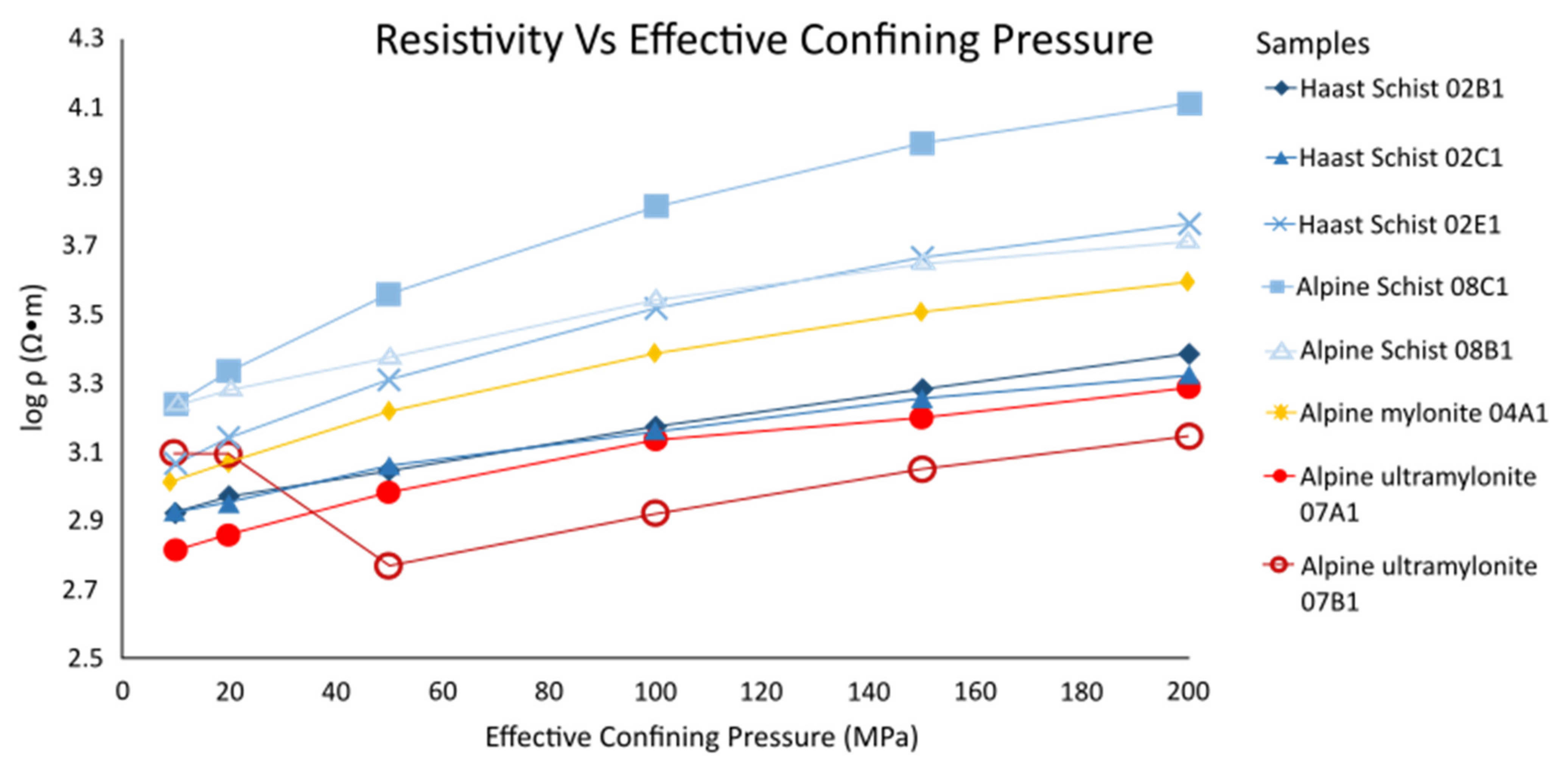
The resistivity of all samples increases with effective confining pressure (Figure 5). Lower grade schists (samples 02B1 and 02C1) and the ultramylonites (samples 07A1 and 07B1) exhibit the lowest values of resistivity, while higher grade schists (08C1 and 02E1) display the greatest resistivity values. Alpine ultramylonite 07B1 exhibits constant conductivity between 0 and 20 MPa during the Second Run, but then its conductivity decreases. This is probably because the sample had not relaxed from the confining pressures in the First Run, but then recovered. Averaged ultramylonite values, typical of rocks within the SAEC (Figure 1C), are 1.7 more conductive than some of the Haast and Alpine Schist values, which are more representative of the host rock surrounding the SAEC.
Systematic relations between rock type, porosity and conductivity are most apparent when considered in terms of proximity to the Alpine Fault, which is a proxy for tectonite fabric maturity and metamorphic facies. While schist samples show a definite decrease in porosity approaching the AFZ, mylonites exhibit less of a correlation between proximity and porosity. When sample resistivity is plotted with distance to the AFZ, schist resistivity increases approaching the AFZ and mylonite resistivity, though low, again does not exhibit a strong trend. However, in mylonites this relationship cannot be determined with confidence, since only three samples were measured (Figure 6). When resistivity is plotted as a function of porosity, schist resistivity increases with decreasing porosity, as would be expected of rocks in which conductivity in pore fluids dominates. Mylonites, on the other hand, exhibit low resistivity at the same porosities at which schists exhibit higher resistivities (Figure 6C).

4.2. Anisotropy of Electrical Properties

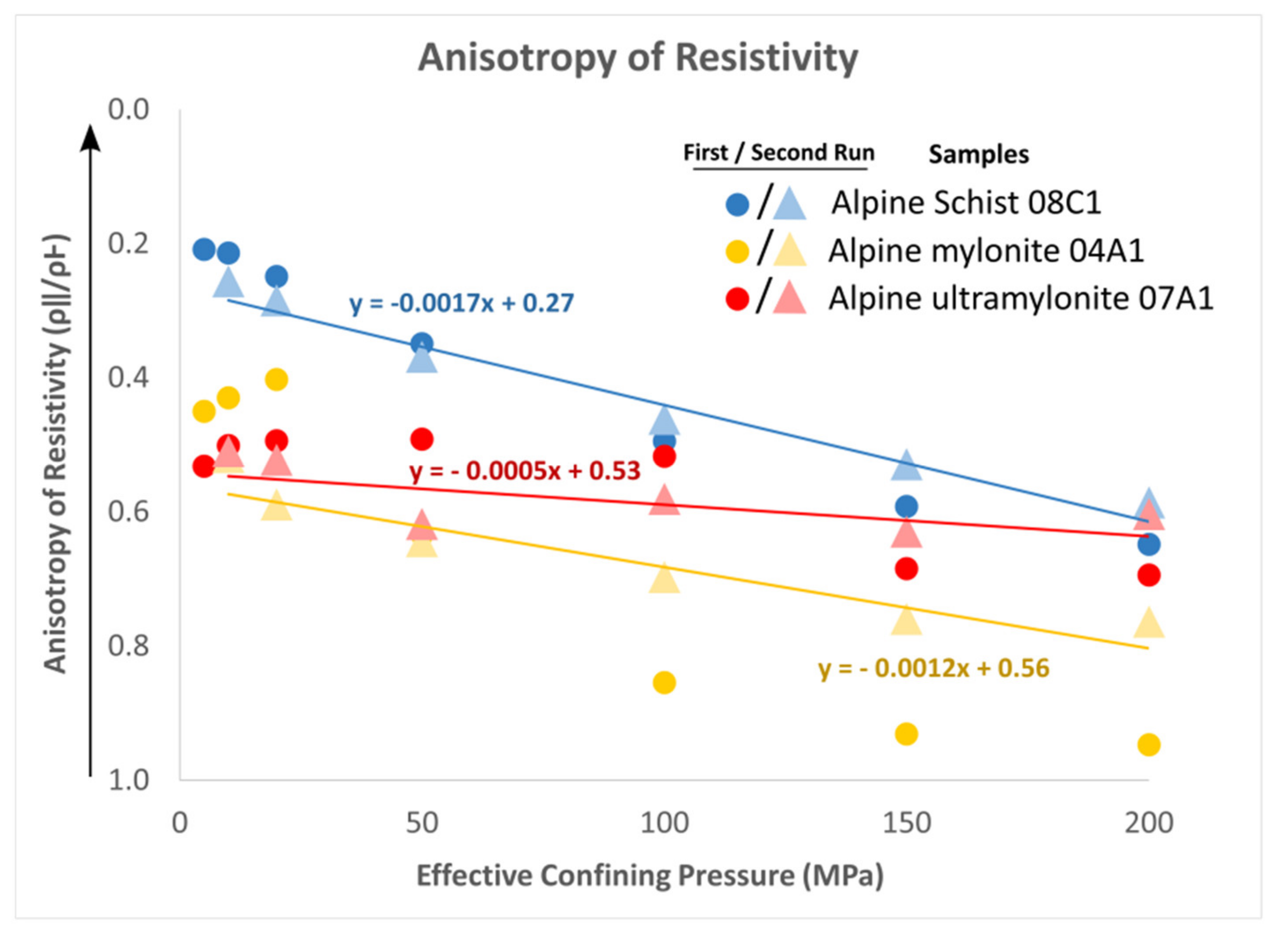
Anisotropy of resistivity (Figure 7) of all the samples decreases with increasing effective confining pressure. The Alpine Schist sample 08C1, with pronounced quartz and feldspar and phyllosilicate layers (Figure 2E), has the highest anisotropy. The Alpine mylonite and ultramylonite, with fine grain texture and homogenized mineral distribution (Figure 2G), are less anisotropic. The change in resistivity anisotropy with effective confining pressure δ (ρ)/δ (peff) is greatest for low-strain schist (08C1) sourced farthest from the fault, and lowest for the high-strain ultramylonite (07A1) closest to the fault. The Alpine Schist 08C1 was collected 2.8 km from the AFZ, the Alpine mylonite 04A1 was collected 0.40 km from the AFZ and the Alpine ultramylonite 07A1 was collected 0.15 km from the AFZ (Table 1).

5. Discussion

5.1. Effect of Progressive Fabric Development on Resistivity and Porosity

The electrical resistivities of the Haast and Alpine Schists have different relationships with porosity compared to Alpine mylonite and ultramylonite. Schist samples exhibit a decrease in porosity and an increase in electrical resistivity approaching the Alpine Fault (Figure 6), which suggests their electrical properties are dominated by charge transport in pore fluids, as expected for saturated porous media [11]. With increasing deformation and metamorphism, these schists would have experienced pore closure by solution-transfer during grain-size sensitive creep, perhaps with a contribution from intracrystalline deformation during progressive schistose fabric development [65,66,67,68]. This explains the decrease in porosity observed in higher metamorphic grade Alpine Schist samples with stronger tectonite fabrics sampled closer to the Alpine Fault (Figure 6, Table 1).
Conversely, mylonites (samples 04A1, 07B1, 07A1) exhibit low resistivity compared to schists at the same porosities (Figure 6). This implies there is a supplemental conductive process present in these mylonitized rocks to compensate for the reduction of pore fluid conductivity. These samples comprise aggregates of (typically low conductivity [53]) silicates, but also contain accessory conductive minerals, notably graphite [63] and micas, which have high quadrature conductivity along EDLs at grain and phase boundaries at elevated temperatures [64]. The most significant difference between mylonites and shists is the degree of tectonite fabric development. As noted previously, mylonitic fabrics mature toward the fault’s principal slip zone, which is associated with textural homogenization, phase mixing, and grain size reduction [41,49,62]. These processes should enhance pathways for surface charge transport because (i) grain size reduction overall increases the proportion of grain or phase boundaries in an aggregate, and the ratio of phase to grain boundaries, and (ii) phase boundaries are easier pathways for charged ion migration than grain boundaries since adjacent mineral grains have low chemical affinity [37,65,66,67,68,69,70]. These textural changes also create a better-linked network of conductive solid phases, including graphites, that are typically distributed in grain boundaries [63], and micas. Overall, such textural changes should enhance conductance along linked solid phase networks and along surfaces (ie. within EDLs). To identify the specific source of the SAEC, such solid phase and surface versus pore fluid conductivity should nevertheless be further tested by repeating the measurements with different electrolyte concentrations.

5.2. Explanation for Anisotropy of Electrical Resistivity

Anisotropy of resistivity for a subset of samples is plotted with increasing effective confining pressure in Figure 7. The anisotropy of all the samples decreases with increasing effective confining pressure. Furthermore, the change in anisotropy of resistivity with effective confining pressure δ (ρ)/δ (peff) (proxied by the trendline slope in Figure 7) correlates to the intensity of sample mylonitization. Alpine Schist 08C1, collected 3.4 km from the Alpine Fault, exhibits a δ (ρ)/δ (peff) of −1.7 × 10⁻³ MPa−1. Alpine mylonite 04A1, collected 0.4 km from the Alpine Fault, has a δ (ρ)/δ (peff) of −1.2 × 10⁻³ MPa−1 and Alpine ultramylonite 07A1, collected 0.1 km from the Alpine Fault, has a δ (ρ)/δ (peff) of −0.5 × 10⁻³ MPa−1.
As noted previously, any observed increase in resistivity with increasing effective confining pressure (Figure 5) is likely related to a diminishing ability of pore fluids to transport charge due to reduced porosity. We can most logically attribute the change in anisotropy with increasing effective confining pressure, which is greatest in schist samples where pore fluid conductivity dominates, to the closure of permeable high aspect-ratio cracks and pores. Fractures and high aspect-ratio pores usually occur parallel to foliation in the weaker phyllosilicate bands, providing a preferred permeability in that orientation in anisotropic or layered rocks such as schist [25,59,60]. This generates resistivity that is lowest parallel to foliation (Figure 7). With increasing effective confining pressure, the anisotropy of permeability is reduced as cracks and high aspect ratio pores close. This results in a decrease in loss of anisotropy in both resistivity and permeability [59,60].
This correlation could explain the observed change in anisotropy in the schist samples, where most of the charge is conducted through pore fluids. Conversely, increasing effective confining pressure has less effect on the anisotropy of resistivity for the mylonite and ultramylonite, which implies that closure of compliant high aspect-ratio cracks and pores has less effect on their resistivity. As permeability decreases, one expects contributions from pore fluid conductivity to decrease and be supplemented by increasing contributions from charge transport in the EDL [56]. While most cracks and high aspect-ratio pores within phyllosilicates may be assumed closed at 200 MPa [25,70,71,72] and effectively closed at 20 MPa in mylonites [25,73,74,75,76], low aspect-ratio (round) pores are less compliant and thus more resistant to closure due to increased effective confining pressure [77,78,79,80,81,82]. Alpine mylonites inherently exhibit a predominately round pore geometry, which could explain why their anisotropy of resistivity changes less than that of schists [25,82].
Figure 8 shows our preferred model correlating anisotropy of resistivity with microstructures of typical schist (samples 02B1, 02C1, 02E1, 08C1, 08B1), mylonite (sample 04A1) and ultramylonite samples (samples 07A1, 07B1). The schist with alternating quartzofeldspathic microlithons and phyllosilicate foliation domains, has weak mica layers that host numerous interconnected high aspect-ratio pores parallel to foliation. Conversely, samples with increasing degrees of mylonitization exhibit less well-oriented micas and have a more homogeneous phase distribution, so the porosity in micas is also less preferentially oriented and connected.

5.3. Comparison with the Southern Alps Electrical Conductor

Direct comparison between our laboratory measurements and the most conductive ultramylonites within the SAEC is not possible. This is because the maximum effective confining pressure at which we made measurements (200 MPa) is equivalent to depths shallower than the brittle-creep transition (less than 7.55 km for an average crustal density of 2700 kg∙m−3). This depth coincides with shallow extents of the SAEC (Figure 1B). Nevertheless, we consider the relations between our laboratory resistivity measurements and resistivity values derived from the MT inversion to investigate processes that enhance conductivity within the in situ fault zone.
First, we compare laboratory resistivity values (Table 1) to MT-derived (in situ) resistivities (Figure 1B) above the brittle-creep transition, where the pressure ranges of measurement are similar. Absolute in situ SAEC (ie. mylonite) resistivities have a range of 10–300 Ω∙m [13], which is comparable in magnitude to our laboratory measurements which range from 230–2900 Ω∙m. In situ host rock Haast and Alpine Schists have resistivities of 1000–10,000 Ω∙m [13], again comparable to our laboratory measurements of 1000–13,000 Ω∙m. Below the brittle-creep transition, in situ mylonite resistivities are in the range 10–300 Ω∙m [13] while in situ host rock schists are in the range of 1000–10,000 Ω∙m [13]. It is observed that in situ mylonite resistivity decreases with depth and effective confining pressure along the fault, while in situ schist resistivity increases with depth (Figure 1A). Both our mylonite and schist resistivity measurements increased with effective confining pressure. The in situ SAEC is 1000 times less resistive than the surrounding Haast and Alpine Schist host rocks [13], but in the laboratory we found our mylonites to only be 1.7 times less resistive than schists. However, as noted previously, we cannot directly compare these deeper in situ values to our laboratory measurements.
Inconsistencies between our sample measurements and the MT-derived resistivities may be due to in situ fluid chemistry, temperatures, or larger regional scale effects not being accounted for in our methods. Discrepancies between hand sample and field scale results have been recognised in the past, and this alone has been shown to influence conductivity values. For example, increasing the scale at which resistivities were measured around the KTB Drillhole from core samples, to in situ borehole surveys to regional audiomagnetotelluric (AMT) scale decreased the resistivity from 3000 to 1000 Ω∙m [83,84,85]. It was also observed that electrical anisotropies in regional AMT surveys around the KTB Drillhole were 3 to 30 times greater than resistivities measured on hand samples [83,84,85].
However, scale and permeability alone cannot explain decreases in resistivity observed in the SAEC and our measurements. With increasing depth and confining pressure, we expect reduced pore fluid volumes and increased resistivity. This is the case for in situ host rocks and for our schist sample measurements. However, the opposite is observed in mylonites. As mentioned previously, the SAEC exhibits a decrease in resistivity and permeability with increasing depth [13,38]. Our mylonite and ultramylonite measurements have low resistivity at the lowest porosities (Figure 6C). This may coincide with our prior inference that charge conduction in the mylonites is supplemented by a process relatively insensitive to confining pressure and porosity, such as solid mineral conduction or effects within EDLs on mineral surfaces [13,56,83,84,85]. We speculate this conductive process is activated and/or amplified by the in situ conditions that generate the 10 Ω∙m resistivities observed in the SAEC, possibly including dynamic, temperature-sensitive creep.

6. Conclusions

The major findings from our measurements of electrical properties and their anisotropy in Haast and Alpine Schists and Alpine mylonites and ultramylonites, at conditions comparable to the crustal seismogenic zone above the brittle-creep transition, are as follows:
  • There is a negative correlation between the resistivity and porosity of Alpine and Haast Schists; both are strongly associated with distance to the AFZ (Figure 6). We infer that the decrease in porosity and the increase in resistivity occurs during progressive development of a schistose tectonite fabric. The negative correlation of these two parameters indicates that the electrical properties of these rocks are dominated by charge transport in pore fluids.
  • Alpine mylonite and ultramylonite samples exhibit low resistivity and low porosity relative to the schist samples. We hypothesize that a conductive process associated with progressive phase mixing and grain size reduction due to mylonitization supplements in pore fluid conduction in Alpine mylonites and ultramylonites. This could either be (i) conductance in linked solid phase networks, or (ii) effects along the EDL, such as surface conductivity, or a combination.
  • This supplementary process increases mylonite sample conductivity to 1.7 times that of Alpine Schist samples in our laboratory measurements. Conversely, the SAEC is 1000 times more conductive than the surrounding crustal host rocks, at depths at which we expect confining pressures to significantly reduce pore fluid volumes. Therefore, we infer that the above supplementary processes, and perhaps others related to dynamic, temperature-sensitive creep, are also active within the SAEC. These remain to be explored in future studies
  • The change in anisotropy of resistivity with increasing effective confining pressure (δ (ρ)/δ (peff)) is lower for Alpine mylonite and ultramylonite than it is for Haast and Alpine Schists. We also attribute this to a decreased dependence on conductivity in fluids hosted in compliant porosity associated with progressive fabric development in these high strain, mylonitized rocks. The change in anisotropy varies since the schists have more anisotropic tectonite fabrics than the mylonites.

Author Contributions

Conceptualization, E.-K.K. and V.T.; methodology, D.L.; validation, D.L.; formal analysis, E.-K.K. and D.L.; investigation, E.-K.K.; resources, V.T. and D.L.; data curation, E.-K.K. and D.L.; writing—original draft preparation, E.-K.K.; writing—review and editing, E.-K.K., V.T. and D.L.; visualization, E.-K.K.; supervision, V.T. All authors have read and agreed to the published version of the manuscript.

Funding

We acknowledge the support of a Royal Society of New Zealand Rutherford Discovery Fellowship (16-UOO-1602) to V.T. This study was partially supported by the U.S. Geological Survey Earthquake Hazards Program.

Data Availability Statement

Figure 5, Figure 6 and Figure 7 are derived from data presented in Table 1. These data can be found at https://doi.org/10.5066/P91A6OMH at the USGS online data repository.

Acknowledgments

The USGS Earthquake Hazards Program is part of the National Earthquake Hazards Reduction Program (NEHRP), established by Congress in 1977, and the USGS Advanced National Seismic System (ANSS) was established by Congress as a NEHRP facility. Any use of trade, firm, or product names is for descriptive purposes only and does not imply endorsement by the U.S. Government. We thank three anonymous reviewers and the journal Editor for comments that led to substantial improvement of the manuscript.

Conflicts of Interest

The authors declare no conflict of interest.

References

  1. Vanyan, L.L.; Shilovsky, A.P.; Okulessky, B.A.; Semenov, V.Y.; Sidelnikova, T.A. Electrical conductivity of the crust of the Siberian platform. Phys. Earth Planet. Inter. 1989, 54, 163–168. [Google Scholar] [CrossRef]
  2. Hyndman, R.; Vanyan, L.; Marquis, G.; Law, L. The origin of electrically conductive lower continental crust: Saline water or graphite? Phys. Earth Planet. Inter. 1993, 81, 325–345. [Google Scholar] [CrossRef]
  3. Hjelt, S. Regional EM studies in the 80′s. Surv. Geophys. 1988, 9, 349–387. [Google Scholar] [CrossRef]
  4. Jones, A. Electrical conductivity of the continental lower crust. In Continental Lower Crust; Fountain, D., Arculus, R., Kay, R., Eds.; Elsevier: Amsterdam, The Netherlands, 1992; pp. 81–143. [Google Scholar]
  5. Korja, T.; Hjelt, S. Electromagnetic studies in the Fennoscandian Shield—electrical conductivity of Precambrian crust. Phys. Earth Planet. Inter. 1993, 81, 107–138. [Google Scholar] [CrossRef]
  6. Leibecker, J.; Gatzemeier, A.; Hönig, M.; Kuras, O.; Soyer, W. Evidence of electrical anisotropic structures in the lower crust and the upper mantle beneath the Rhenish Shield. Earth Planet. Sci. Lett. 2002, 202, 289–302. [Google Scholar] [CrossRef]
  7. Yang, X. Origin of high electrical conductivity in the lower continental crust: A review. Surv. Geophys. 2011, 32, 875–903. [Google Scholar] [CrossRef]
  8. Vanyan, L.; Tezkan, B.; Palshin, N. Low electrical resistivity and seismic velocity at the base of the upper crust as indicator of rheologically weak layer. Surv. Geophys. 2001, 22, 131–154. [Google Scholar] [CrossRef]
  9. Haak, V.; Hutton, V.S. Electrical resistivity in continental lower crust. Geol. Soc. Lond. Spec. Publ. 1986, 24, 35–49. [Google Scholar] [CrossRef]
  10. Bahr, K.; Berktold, A.; Brink, H.; Haak, V.; Hofer, S.; Jiidicke, H.; Junge, A.; Junge, A.; Knddel, K.; Losecke, W.; et al. An electrical resistivity crustal section from the Alps to the Baltic Sea (central segment of the EGT). Tectonophysics 1992, 207, 123–139. [Google Scholar] [CrossRef]
  11. Olhoeft, G. Electrical Properties of Rocks. In Physical Properties of Rocks and Minerals, CINDAS Data Series on Material Properties; McGraw-Hill: New York, NY, USA, 1981; Volume II, pp. 262–278. [Google Scholar]
  12. Ucok, H. Temperature Dependence of the Electrical Resistivity of Aqueous Salt Solutions and Solution-Saturated Porous Rocks; University of Southern California: Los Angeles, CA, USA, 1979. [Google Scholar]
  13. Wannamaker, P.; Jiracek, G.; Stodt, J.; Caldwell, T.; Gonzalez, V.; Mcknight, J.; Porter, A. Fluid generation and pathways beneath an active compressional orogen, the New Zealand Southern Alps, inferred from magnetotelluric data. J. Geophys. Res. 2002, 107, 2117. [Google Scholar] [CrossRef] [Green Version]
  14. Li, S.; Unsworth, M.; Booker, J.; Wei, W.; Tan, H.; Jones, A. Partial melt or aqueous fluid in the mid-crust of Southern Tibet? Constraints from INDEPTH magnetotelluric data. Geophys. J. Int. 2003, 153, 289–304. [Google Scholar] [CrossRef] [Green Version]
  15. Hermance, F. The electrical conductivity of materials containing partial melt: A simple model from Archie’s Law. Geophys. Res. Lett. 1979, 6, 613–616. [Google Scholar] [CrossRef]
  16. Frost, B.; Fyfe, W.; Tazaki, K.; Chan, T. Grain-boundary graphite in rocks and implications for high electrical conductivity in the lower crust. Nature 1989, 340, 134–136. [Google Scholar] [CrossRef]
  17. Shankland, T.; Duba, A.; Mathez, E.; Peach, C. Increase of electrical conductivity with pressure as an indicator of conduction through a solid phase in midcrustal rocks. J. Geophys. Res. 1997, 102, 14741–14750. [Google Scholar] [CrossRef] [Green Version]
  18. Watson, H.; Roberts, J.; Tyburczy, J. Effect of conductive impurities on electrical conductivity in polycrystalline olivine. Geophys. Res. Lett. 2010, 37, L02302. [Google Scholar] [CrossRef]
  19. Jiracek, G.; Gonzalez, V.; Caldwell, T.; Wannamaker, P.; Kilb, D. Seismogenic, Electrically Conductive, and Fluid Zones at Continental Plate Boundaries in New Zealand, Himalaya, and California. Geophys. Monogr. Ser. 2007, 175, 347. [Google Scholar] [CrossRef]
  20. Christensen, N.; Okaya, D. Compressional and shear wave velocities in South Island, New Zealand rocks and their application to the interpretation of seismological models of the New Zealand crust. Geophys. Monogr. Ser. 2007, 175, 123–155. [Google Scholar] [CrossRef]
  21. Norris, R.; Cooper, A. The Alpine Fault, New Zealand: Surface geology and field relationships. Geophys. Monogr. Ser. 2007, 175, 157–175. [Google Scholar] [CrossRef]
  22. Menzies, C.; Teagle, D.; Niedermann, S.; Cox, S.; Craw, D.; Zimmer, M.; Cooper, M.; Erzinger, J. The fluid budget of a continental plate boundary fault: Quantification from the Alpine Fault, New Zealand. Earth Planet. Sci. Lett. 2016, 445, 125–136. [Google Scholar] [CrossRef] [Green Version]
  23. Greenroyd, C.; Yu, J.; Melhuish, A.; Ravens, J.; Davey, F.; Maslen, G.; SIGHT Working Group. New Zealand South Island Geophysical Transect (SIGHT): Marine Active-Source Seismic Component—A Processing Summary; Science Report; Institute of Geological & Nuclear Sciences: Lower Hutt, New Zealand, 2003; Volume 20. [Google Scholar]
  24. Van Avendonk, H.; Holbrook, S.; Okaya, D.; Austin, J.; Davey, F.; Stern, T. Continental crust under compression: A seismic refraction study of South Island Geophysical Transect I, South Island, New Zealand. J. Geophys. Res. Solid Earth 2004, 109, B06302. [Google Scholar] [CrossRef]
  25. Dempsey, E.; Prior, D.; Mariani, E.; Toy, V.; Tatham, D. Mica-controlled anisotropy within mid-to-upper crustal mylonites: An EBSD study of mica fabrics in the Alpine Fault Zone, New Zealand. Geol. Soc. Lond. Spec. Publ. 2011, 360, 33–47. [Google Scholar] [CrossRef]
  26. Adam, L.; Frehner, M.; Sauer, K.; Toy, V.; Guerin-Marthe, S. Seismic anisotropy and its impact on imaging the shallow Alpine Fault: An experimental and modeling perspective. J. Geophys. Res. Solid Earth 2020, 125, e2019JB019029. [Google Scholar] [CrossRef]
  27. Cox, S.; Menzies, C.; Sutherland, R.; Denys, P.; Chamberlain, C.; Teagle, D. Changes in hot spring temperature and hydrogeology of the Alpine Fault hanging wall, New Zealand, induced by distal South Island earthquakes. Geofluids 2015, 15, 216–239. [Google Scholar] [CrossRef] [Green Version]
  28. Cooper, A.; Palin, J.M. Two-sided accretion and polyphase metamorphism in the Haast Schist belt, New Zealand: Constraints from detrial zircon geochronology. Geol. Soc. Am. Bull. 2018, 130, 1501–1518. [Google Scholar] [CrossRef]
  29. Norris, R.; Cooper, A. Late Quaternary slip rates and slip partitioning on the Alpine Fault, New Zealand. J. Struct. Geol. 2001, 23, 507–520. [Google Scholar] [CrossRef]
  30. Jacobson, A.; Blum, J.; Chamberlain, C.; Craw, D.; Koons, P. Climatic and tectonic controls on chemical weathering in the New Zealand Southern Alps. Geochim. Cosmochim. Acta 2003, 67, 29–46. [Google Scholar] [CrossRef]
  31. Ingham, M. Electrical structure along a transect of the central South Island, New Zealand. N. Z. J. Geol. Geophys. 1995, 38, 559–563. [Google Scholar] [CrossRef]
  32. Ingham, M. Magnetotelluric soundings across the Southern Alps orogen, South Island of New Zealand: Data presentation and preliminary interpretation. Phys. Earth Planet. Inter. 1996, 94, 291–306. [Google Scholar] [CrossRef]
  33. Haak, V.; Stoll, J.; Winter, H. Why is the electrical resistivity around the KTB hole so low? Phys. Earth Planet. Inter. 1991, 66, 12–23. [Google Scholar] [CrossRef]
  34. Lemonnier, C.; Marquis, G.; Perrier, F.; Avouac, J.-P.; Chitrakar, G.; Kafle, B.; Sapkota, S.; Gautam, U.; Tiwari, D.; Bano, M. Electrical structure of the Himalaya of Central Nepal: High conductivity around the mid-crustal ramp along the MHT. Geophys. Res. Lett. 1999, 26, 3261–3264. [Google Scholar] [CrossRef] [Green Version]
  35. Uyeshima, M.; Ogawa, Y.; Honkura, Y.; Koyama, S.; Ujihara, N.; Mogi, T.; Yamaya, Y.; Harada, M.; Yamaguchi, S.; Shiozaki, I.; et al. Resistivity imaging across the source region of the 2004 Mid-Niigata Prefecture earthquake (M6.8), central Japan. Earth Planets Space 2005, 57, 441–446. [Google Scholar] [CrossRef] [Green Version]
  36. Bailey, R. Trapping of aqueous fluids in the deep crust. Geophys. Res. Lett. 1990, 17, 1129–1132. [Google Scholar] [CrossRef]
  37. Watson, E.; Brenan, J. Fluids in the lithosphere, 1. Experimentally-determined wetting characteristics of CO2-H2O fluids and their implications for fluid transport, host-rock physical properties, and fluid inclusion formation. Earth Planet. Sci. Lett. 1987, 85, 497–515. [Google Scholar] [CrossRef]
  38. Yardley, B.W.D.; Valley, J.W. The petrologic case for a dry lower crust. J. Geophys. Res. Solid Earth 1997, 102, 12173–12185. [Google Scholar] [CrossRef]
  39. Little, T.; Cox, S.; Vry, J.; Batt, G. Variations in exhumation level and uplift rate along the oblique-slip Alpine Fault, Central Southern Alps, New Zealand. Geol. Soc. Am. Bull. 2005, 117, 707–723. [Google Scholar] [CrossRef]
  40. Sutherland, R.; Townend, J.; Toy, V.; Upton, P.; Coussens, J.; Allen, M.; Baratin, L.-M.; Barth, N.; Becroft, L.; Boese, C.; et al. Extreme hydrothermal conditions at an active plate-bounding fault. Nature 2017, 546, 137–140. [Google Scholar] [CrossRef] [Green Version]
  41. Norris, R.; Cooper, A. Very high strains recorded in mylonites along the Alpine Fault, New Zealand: Implications for the deep structure of plate boundary faults. J. Struct. Geol. 2003, 25, 2141–2157. [Google Scholar] [CrossRef]
  42. Walcott, R. Present tectonics and Late Cenozoic evolution of New Zealand. Geophys. J. Int. 1978, 52, 137–164. [Google Scholar] [CrossRef] [Green Version]
  43. Norris, R. A geometrical study of finite strain and bending in the South Island. J. R. Soc. N. Z. 1979, 18, 21–28. [Google Scholar]
  44. Mortimer, N. Metamorphic discontinuities in orogenic belts: Example of the garnet-biotite-albite zone in the Otago Schist, New Zealand. Int. J. Earth Sci. 2000, 89, 295–306. [Google Scholar] [CrossRef]
  45. Toy, V.; Boulton, C.; Sutherland, R.; Townend, J.; Norris, R.J.; Little, T.A.; Prior, D.G.; Mariani, E.; Faulkner, D.; Menzies, C.D.; et al. Fault rock lithologies and architecture of the central Alpine Fault, New Zealand, revealed by DFDP-1 drilling. Lithosphere 2015, 7, 155–173. [Google Scholar] [CrossRef] [Green Version]
  46. Sutherland, R.S.; Townend, J.; Toy, V.G. Deep Fault Drilling Project (DFDP), Alpine Fault Boreholes DFDP-2A and DFDP-2B Technical Completion Report; GNS Science Report; DFDP-2 Science Party: Lower Hutt, New Zealand, 2015; Volume 50. [Google Scholar]
  47. Toy, V.; Sutherland, R.; Townend, J.; Allen, M.J.; Becroft, L.; Boles, A.; Boulton, C.; Carpenter, B.; Cooper, A.; Cox, S.C.; et al. Bedrock geology of DFDP-2B, central Alpine Fault, New Zealand. N. Z. J. Geol. Geophys. 2017, 60, 497–518. [Google Scholar] [CrossRef] [Green Version]
  48. Koons, P. Some thermal and mechanical consequences of rapid uplift: An example from the Southern Alps, New Zealand. Earth Planet. Sci. Lett. 1987, 86, 307–319. [Google Scholar] [CrossRef]
  49. Little, T.; Holcombe, R.; Ilg, B. Ductile fabrics in the zone of active oblique convergence near the Alpine Fault, New Zealand: Identifying the neotectonic overprint. J. Struct. Geol. 2002, 24, 193–217. [Google Scholar] [CrossRef]
  50. Massiot, C.; Célérier, B.; Doan, M.-L.; Little, T.A.; Townend, J.; McNamara, D.D.; Williams, J.; Schmitt, D.R.; Toy, V.G.; Sutherland, R.; et al. The Alpine Fault hanging wall viewed from within: Structural analysis of ultrasonic image logs in the DFDP-2B Borehole, New Zealand. Geochem. Geophys. Geosyst. 2018, 19, 2492–2515. [Google Scholar] [CrossRef] [Green Version]
  51. Billia, M.; Timms, N.; Toy, V.; Hart, R.; Prior, D. Grain boundary dissolution porosity in quartzofeldspathic ultramylonites: Implications for permeability enhancement and weakening of mid-crustal shear zones. J. Struct. Geol. 2013, 53, 2–14. [Google Scholar] [CrossRef]
  52. Fusseis, F.; Regenauer-Lieb, K.; Liu, J.; Hough, R.; Carlo, F. Creep cavitation can establish a dynamic granular fluid pump in ductile shear zones. Nature 2009, 459, 974–977. [Google Scholar] [CrossRef]
  53. Olhoeft, G. Electrical properties, initial reports on the Petrophysics laboratory. U.S. Geol. Surv. Circ. 1979, 789, 1–25. [Google Scholar]
  54. Revil, A.; Cathles, L.; Losh, S.; Nunn, J. Electrical conductivity in shaly sands with geophysical applications. J. Geophys. Res. 1998, 103, 23925–23936. [Google Scholar] [CrossRef]
  55. Revil, A.; Glover, P. Theory of ionic-surface electrical conduction in porous media. Phys. Rev. B 1997, 55, 1757–1773. [Google Scholar] [CrossRef] [Green Version]
  56. Revil, A.; Coperey, A.; Shao, Z.; Florsch, N.; Fabricius, I.L.; Deng, Y.; Delsman, J.R.; Pauw, P.S.; Karaoulis, M.; De Louw, P.G.B.; et al. Complex conductivity of soils. Water Resour. Res. 2017, 53, 7121–7147. [Google Scholar] [CrossRef] [Green Version]
  57. Archie, G. The Electrical Resistivity Log as an Aid in Determining Some Reservoir Characteristics. Trans. AIME 1942, 146, 54–62. [Google Scholar] [CrossRef]
  58. Siegesmund, S.; Vollbrecht, A.; Nover, G. Anisotropy of compressional wave velocities, complex electrical resistivity and magnetic susceptibility of mylonites from the deeper crust and their relation to the rock fabric. Earth Planet. Sci. Lett. 1991, 105, 247–259. [Google Scholar] [CrossRef]
  59. Zisser, N.; Nover, G. Anisotropy of permeability and complex resistivity of tight sand-stones subjected to hydrostatic pressure. J. Appl. Geophys. 2009, 68, 356–370. [Google Scholar] [CrossRef]
  60. Brace, W.F. Permeability from resistivity and pore shape. J. Geophys. Res. 1977, 82, 3343–3349. [Google Scholar] [CrossRef]
  61. Lockner, D.; Byerlee, J. Complex resistivity measurements of confined rock. J. Geophys. Res. 1985, 90, 7837–7848. [Google Scholar] [CrossRef]
  62. Toy, V.G. Rheology of the Alpine Fault Mylonite Zone: Deformation Processes at and below the Base of the Seismogenic Zone in a Major Plate Boundary Shear Zone. Ph.D. Thesis, University of Otago, Dunedin, New Zealand, 2008; 629p. [Google Scholar]
  63. Kirilova, M.; Toy, V.G.; Timms, N.; Halfpenny, A.; Menzies, C.; Craw, D.; Beyssac, O.; Sutherland, R.; Townend, J.; Boulton, C.; et al. Textural changes of graphitic carbon by tectonic and hydrothermal processes in an active plate boundary fault zone, Alpine Fault, New Zealand. Geol. Soc. Lond. Spec. Publ. 2018, 453, 205–223. [Google Scholar] [CrossRef] [Green Version]
  64. Saltas, V.; Pentari, D.; Vallianatos, F. Complex electrical conductivity of biotite and muscovite micas at elevated temperatures: A comparative study. Materials 2021, 13, 3513. [Google Scholar] [CrossRef]
  65. Kaselow, A.; Shapiro, S. Stress sensitivity of elastic moduli and electrical resistivity in porous rocks. J. Geophys. Eng. 2004, 1, 1. [Google Scholar] [CrossRef]
  66. Dobe, R.; Das, A.; Mukherjee, R.; Gupta, S. Evaluation of grain boundaries as percolation pathways in quartz-rich continental crust using Atomic Force Microscopy. Sci. Rep. 2021, 11, 9831. [Google Scholar] [CrossRef]
  67. Morrow, C.; Lockner, D.A.; Hickman, S. Low resistivity and permeability in actively deforming shear zones on the San Andreas Fault at SAFOD. J. Geophys. Res. 2015, 120, 8240–8258. [Google Scholar] [CrossRef]
  68. Norris, R.J.; Bishop, D.G. Deformed conglomerates and textural zones in the Otago Schists, South Island, New Zealand. Tectonophysics 1990, 174, 331–349. [Google Scholar] [CrossRef]
  69. Hay, R.; Evans, B. Intergranular distribution of pore fluid and the nature of high-angle grain boundaries in limestone and marble. J. Geophys. Res. 1988, 93, 8959–8974. [Google Scholar] [CrossRef]
  70. Ji, S.; Wang, Q.; Marcotte, D.; Salisbury, M.H.; Xu, Z. P wave velocities, anisotropy and hysteresis in ultrahigh-pressure metamorphic rocks as a function of confining pressure. J. Geophys. Res. Solid Earth 2007, 112, B09204. [Google Scholar] [CrossRef] [Green Version]
  71. Brace, W.F. Some new measurements of linear compressibility of rocks. J. Geophys. Res. 1965, 70, 391–398. [Google Scholar] [CrossRef]
  72. Birch, F. The velocity of compressional waves in rocks to 10 kilobars: 2. J. Geophys. Res. 1961, 66, 2199–2224. [Google Scholar] [CrossRef]
  73. Kern, H.; Wenk, H.-R. Fabric-related velocity anisotropy and shear wave splitting in rocks from Santa Rosa Mylonite Zone, California. J. Geophys. Res. 1990, 95, 11213–11223. [Google Scholar] [CrossRef]
  74. Ivankina, T.; Kern, H.; Nikitin, A. Directional dependence of P- and S-wave propagation and polarization in foliated rocks from the Kola superdeep well: Evidence from laboratory measurements and calculations based on TOF neutron diffraction. Tectonophysics 2005, 407, 25–42. [Google Scholar] [CrossRef]
  75. Burlini, L.; Kunze, K. Fabric and seismic properties of Carrara marble mylonite. Phys. Chem. Earth Part A Solid Earth Geod. 2000, 25, 133–139. [Google Scholar] [CrossRef]
  76. Jones, T.; Nur, A. Seismic velocity and anisotropy in mylonites and the reflectivity of deep crystal fault zones. Geology 1982, 10, 260–263. [Google Scholar] [CrossRef]
  77. Garboczi, E.; Snyder, K.; Douglas, J.; Thorpe, M.F. Geometrical percolation threshold of overlapping ellipsoids. Phys. Rev. E 1995, 52, 819–828. [Google Scholar] [CrossRef] [PubMed] [Green Version]
  78. Gueguen, Y.; Dienes, J. Transport properties of rock from statistics and percolation. Math. Geol. 1989, 21, 1–13. [Google Scholar] [CrossRef]
  79. Sarout, J. Impact of pore space topology on permeability, cut-off frequencies and validity of wave propagation theories. Geophys. J. Int. 2012, 189, 481–492. [Google Scholar] [CrossRef] [Green Version]
  80. Sarout, J.; Cazes, E.; Delle Piane, C.; Arena, A.; Esteban, L. Stress-dependent permeability and wave dispersion in tight cracked rocks: Experimental validation of simple effective medium models. J. Geophys. Res. Solid Earth 2017, 122, 6180–6201. [Google Scholar] [CrossRef]
  81. Tsuji, T.; Iturrino, G. Velocity-porosity relationships in oceanic basalt from eastern flank of the Juan de Fuca Ridge: The effect of crack closure on seismic velocity. Explor. Geophys. 2008, 39, 41–51. [Google Scholar] [CrossRef]
  82. Charoensawan, J.; Adam, L.; Ofman, M.; Toy, V.; Simpson, J.; Zhong, X.; Schuck, B. Fracture shape and orientation contributions to P-wave velocity and anisotropy of Alpine Fault Mylonites. Front. Earth Sci. 2021, 9, 238. [Google Scholar] [CrossRef]
  83. Bahr, K. Electrical anisotropy and conductivity distribution functions of fractal random networks and of the crust: The scale effect of connectivity. Geophys. J. Int. 1997, 130, 649–660. [Google Scholar] [CrossRef]
  84. Guéguen, Y.; Gavrilenk, P.; Le Ravalec, M. Scales of rock permeability. Surv. Geophys. 1996, 17, 245–263. [Google Scholar] [CrossRef]
  85. Hsieh, P.; Shapiro, A.; Goode, D.; Tiedeman, C. Hydraulic Conductivity of Fractured Crystalline Rocks from Meter to Kilometer Scale: Observations from the Mirror Lake Site. In Proceedings of the New Hampshire Conference, Lincoln, NH, USA, 6–9 June 1994. [Google Scholar]
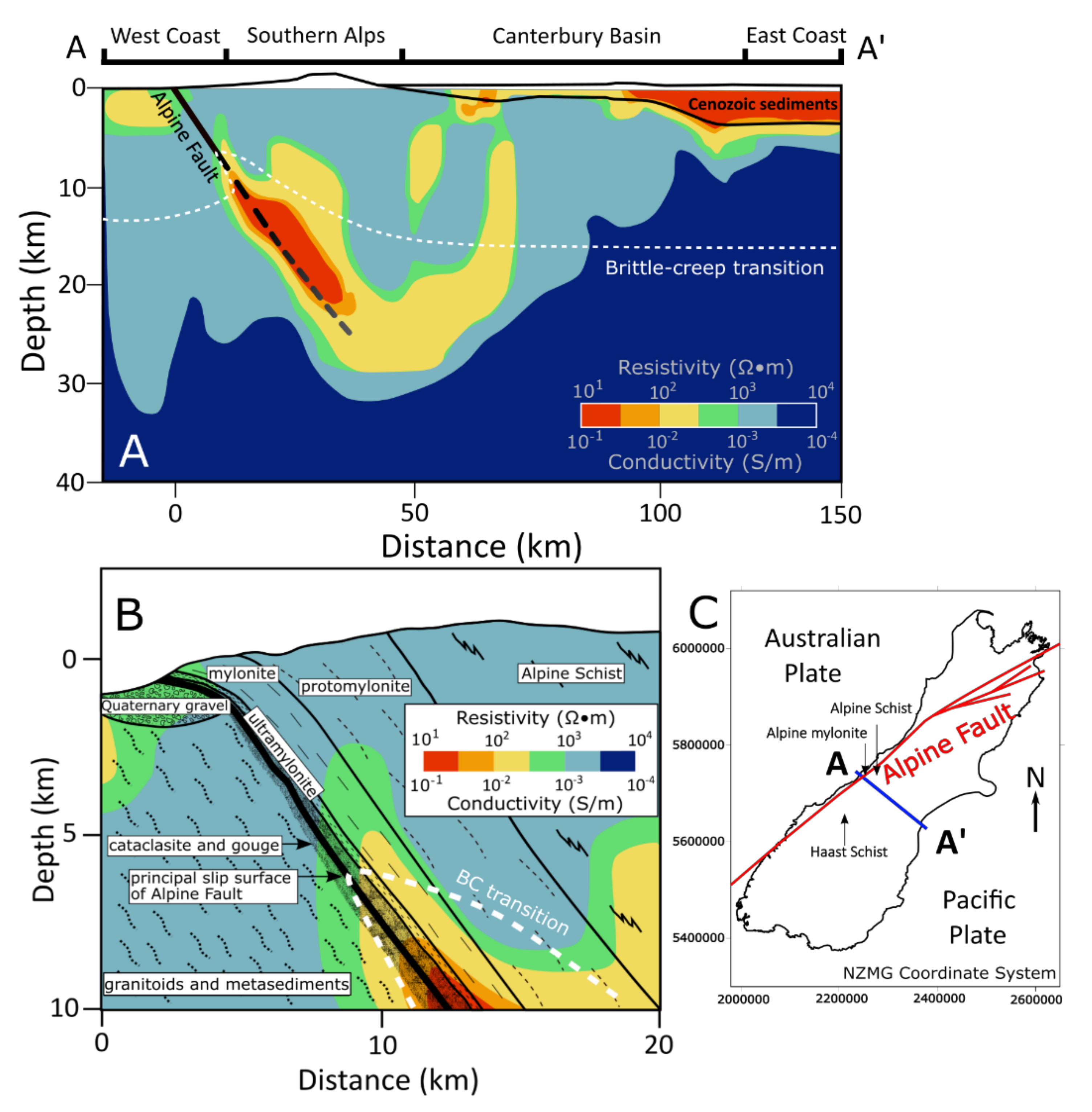
Figure 1. (A). Crustal-scale cross section AA’ of the Alpine Fault Zone (AFZ) conductivity structure and the surrounding crust based on magnetotelluric surveys (MT) inversions [13,20,21,22,23,24,25,26]. The zone of increased conductivity represents the Southern Alps Anomalous Electrical Conductor (SAEC). The brittle-creep (B,C) transition marks the base of the seismogenic zone and the top of the ductile shear regime. The zone of increased conductivity represents the electrical structure identified as the SAEC. (B). Smaller scale cross-section of the SAEC with associated fault rocks and geologic units [13,20,21,22,23,24,25,26,27]. (C). Regional map of South Island, New Zealand, showing the Alpine Fault trace, the cross-section extent and sample locations.
Geosciences 12 00121 g001
Figure 2. Photomicrographs illustrating mineralogy and microstructures of Haast Schist (AC), Alpine Schist (D,E), Alpine mylonite (F), and Alpine ultramylonite (G,H) samples. These are presented in order of increasing metamorphic grade, strain, and decreasing distance to the Alpine Fault. Mineral abbreviations are Qtz: quartz, Fsp: feldspar, Bt: Biotite, Mv: Muscovite, Cht: chlorite, Grt: garnet. Note the larger grain size—particularly apparent when observing biotite grains—and layered fabric of the schists compared to the finer-grained, more homogenous ultramylonites and mylonites, which also exhibit more phase than grain boundaries.
Geosciences 12 00121 g002
Figure 3. Simplified circuit diagram of charge transport in saturated rock [56]. The in-phase component of conductivity (σ′) is controlled by the ratio of fluid conductivity (σf) and the formation factor (F), and by surface conductivity (σs) along the electric double layer (EDL) on grain or phase boundaries. The quadrature component of conductivity (σ″) is controlled by polarization and other phenomena in the EDL, including surface conductivity [56].
Geosciences 12 00121 g003
Figure 4. Experimental setup to test electrical resistivity across samples under effective confining pressure [61]. Resistivity was measured with an Agilent 4284A Precision Inductance Capacitance Resistivity LCR meter using a 4-electrode set up, where two outer electrodes drive current and two high impedance inner electrodes measure voltage decrease across the sample. The resulting voltage difference (∆V) was used to calculate resistivity by dividing ∆V by the length of the sample parallel to current flow. Electrodes were made of platinum mesh coated with platinum black and separated from the sample and each other by wafers of Berea sandstone. The assembled sample column, including the platinum electrode wires, were each jacketed in heat shrink tubing jackets. The sample column was connected to a pore pressure pump for independent pore fluid pressure control and suspended in silicon oil within the confining pressure apparatus to maintain electrical isolation [61]. Samples were saturated in a 0.1 M KCl brine and measurements were taken at a controlled temperature of 23.3 ± 0.3 °C, a constant pore pressure of 20 bar and at discrete frequencies 20 and 100 Hz.
Geosciences 12 00121 g004
Figure 5. Sample resistivity, measured under increasing effective confining pressure, at 20 Hz and 20 MPa pore fluid pressure. Measurements were made during the Second Run, following the First Run, with a maximum effective confining pressure of 200 MPa. The samples depicted in the legend, from top to bottom, have accommodated progressively larger mylonitic shear strains. The blue data are from Haast and Alpine Schist, the yellow from Alpine mylonite and the red from Alpine ultramylonite.
Geosciences 12 00121 g005
Figure 6. Resistivities measured on samples under increasing effective confining pressure. (A). Plot of sample porosities versus Alpine Fault Proximity. (B). Plot of sample resistivity versus Alpine Fault proximity. These measurements were made at 20 Hz during the Second Run at 100 MPa effective confining pressure (20 MPa pore fluid pressure). (C). Plot of sample resistivity versus sample porosity fraction.
Geosciences 12 00121 g006
Figure 7. Anisotropy of resistivity of Alpine Fault rocks over ranges of effective confining pressure, derived from both First and Second Run data. Anisotropy of resistivity here was defined as the ratio of the resistivity parallel to foliation (ρ) to the resistivity perpendicular to foliation (ρ˫), as shown in Equation (6). Therefore, anisotropy is greater at 0 than 1, indicated by the arrow on the vertical axis. The trendline and the corresponding equation, based on Second Run data, is depicted for each sample. The Second Run data were used to generate the trendlines, since they display more systematic linear relations to confining pressure, which we infer relates to closure of exhumation cracks during the First Run.
Geosciences 12 00121 g007
Figure 8. Schematic illustrations of microporosity, showing how differential porosity closure may explain the observed change in anisotropy of resistivity with effective confining pressure δ (ρ)/δ (peff). Compliant pores in phyllosilicate foliation domains impose an anisotropic permeability, and thus resistivity, in the Alpine Schists. Conversely, in Alpine mylonite and ultramylonite, both compliant and non-compliant pores lack a preferential orientation, so their closure has a less significant effect on the change in anisotropy of resistivity with increasing effective confining pressure. This is denoted by a decrease in electric current arrow size in the diagram for the two samples with increasing effective confining pressure.
Geosciences 12 00121 g008
Table 1. Sample Resistivity (Ω∙m).
Haast SchistAlpine SchistAlpine MyloniteAlpine Ultramylonite
02B102C102E108B108C108C1 *04A104A1 *07A107A1 *07B1
Φ0.0540.0390.0210.0180.0120.0120.0150.0150.0180.0180.010
Distance to AFZ (km)13.512.010.53.42.82.80.400.400.150.150.12
peff (MPa)
First Run544950661713702861100757386552294231
1049556075816403511320981485644323270
205676711040188046817301330653785388329
50733908174023908352960133010101020502466
100116012302590309015305100179015501380714717
1501470165038103730221085102320200018101240977
2001970198050104330281011,60028402470229015901250
Second Run1083784411501780468173010205938754521250
2094190013901910556216011507469635101250
5011101150204023908983610166011601200750588
1001490143032903480163064802430176018901110831
15019101810462044802400992032102380231014701120
2002430210057905160306012,90039602870282017201400
Resistivity data measured at 20 Hz over a range of effective confining pressures. All resistivity measurements were made with sample foliation oriented perpendicular to the direction of current flow, except the asterisked (*) samples which were oriented with sample foliation parallel to the direction of current flow. Samples are ordered from left to right with increasing degree of shear strain.
Publisher’s Note: MDPI stays neutral with regard to jurisdictional claims in published maps and institutional affiliations.