Article

Distribution and Morphometry of Thermocirques in the North of West Siberia, Russia

1
Institute of Ecological and Agricultural Biology (X-BIO), University of Tyumen, Volodarsky Street, 6, Tyumen 625003, Russia
2
Earth Cryosphere Institute, Tyumen Scientific Centre SB RAS, Malygin Str., 86, box 1230, Tyumen 625026, Russia
3
Alfred Wegener Institute for Polar and Marine Research, Telegrafenberg A 45, 14473 Potsdam, Germany
4
Institute of Geosciences, University of Potsdam, Karl-Liebknecht-Str. 24-25, 14476 Potsdam, Germany
*
Author to whom correspondence should be addressed.
Geosciences 2023, 13(6), 167; https://doi.org/10.3390/geosciences13060167
Submission received: 30 April 2023 / Revised: 26 May 2023 / Accepted: 28 May 2023 / Published: 3 June 2023

Abstract

:
The Arctic zone of West Siberia (Yamal and Gydan peninsulas) is an area with continuous permafrost and tabular ground ice close to the surface, active thermodenudation, and related landforms: retrogressive thaw slumps (RTS); in Russian referred to as thermocirques (TC). The dimensions of most TCs have not been determined so far. We use Sentinel 2 imagery to measure each TC area ranging from 0.55 to 38 ha with a median of 2.5 ha. Around 95% of TCs have an area of less than 10 ha. The largest areas are gained due to the merging of several neighboring TCs. The ArcticDEM is used to determine TC edge elevation and slope angle. In general, the Median TC of the Yamal peninsula has an area of 1.8 ha, an elevation of the edge of 17.7 m, and a slope angle of 2.5°. The Median TC of the Gydan peninsula has an area of 2.6 ha, elevation of the edge of 29.4 m, and slope angle of 3°. TCs of the Gydan peninsula occupy higher positions and slightly steeper slopes compared to TCs of the Yamal peninsula. The ranges of the median and the largest TC areas are consistent with the reported RTS dimensions in North America.

1. Introduction

Ice-rich permafrost areas are subject to thermodenudation. This process is related to the thawing of ice-bearing deposits on slopes and removing the thawed material downslope to form an earth flow or mudflow. This process was first thoroughly analyzed by [1,2,3]. The theory was then further developed in [4] as a complex of processes on slopes associated with ground ice melting, producing mass movement and concavities of various shapes.
In recent years, due to observed climatic trends, primary research interest has been attracted by retrogressive thaw slumps (RTS) (or earth flows in traditional landslide terminology), a relief-forming process producing remarkable landforms referred to in the Russian literature as thermocirques (TC). In English, these landforms are known as RTS, which in our opinion, is confusing when the process and the resulting landform originating from several RTS episodes has the same name. RTSs are developing in a polycyclic fashion: they can be active for years and stabilized for decades, and then re-initiate [5,6]. Due to the RTS polycyclic nature, the use of a different term for a landform is justified. So, TC is an extensive landform resulting from several multiple-aged multi-directional RTSs in association with other simultaneous cryogenic processes, especially thermoerosion [4]. TCs, and their dimensions, are the main object of this study.
TCs are specific dynamical geomorphic features of ice-rich permafrost in the Arctic or mountains [5]. TC may reach the size of several hundred meters along the retreating headwall. The initiation of TC is related to the melting of ground ice below the upper permafrost table. Such melting may result from the increase in an active layer thickness [4], coastal erosion [7], active layer detachments, or other disturbances [8]. These all lead to slope failures, exposure of ice, and consecutive earth flows or mudflows (depending on the amount of mobilized water liquefying the sediments) (Figure 1).
TCs are developing in relation to climate fluctuations (temporal control) and environmental–geologic–cryolithological patterns (spatial control). The combination of these controls results in the alternation of active and stable stages in TC development. The dynamics of a TC, thus, are an essential object of study as a factor of relief changes, permafrost trends, and geobotanic, hydrologic, geochemical, and carbon-cycle effects [9,10,11].
At the same time, there are no published maps or spatial databases of TCs in Russia or in the entire Arctic. So far, most TC studies in Russia are linked to West Siberia and are mainly based on fieldwork at local key sites [12,13]. Therefore, there still is no understanding of the scale of active TC formation, the range of their dimensions, topographic characteristics, and the rate of ongoing changes for the whole area of West Siberia. In our previous work, the first TC inventory in West Siberia was created and arranged in a dataset of 439 objects [14]. Information concerning TC orientation was manually collected using visual indicators based on the free satellite imagery collection of Yandex.Maps and were statistically processed [14]. Additional 45 TCs were added to the dataset and jointly analyzed in this study.
Most complications in identifying TCs lie in (1) variance of approaches determining the outline of a TC, (2) mapping small features using relatively low-resolution imagery, and (3) differentiating between thermodenudation landforms of different mechanisms (such as active-layer detachments) or features of a different origin (such as kurums or talus). To overcome these complications, we use the advantage of both published and our own field data, including tachometry, photography, and UAV survey, to verify remote-sensing interpretation.
In this research, we have used TC locations from the expanded dataset from [14] to measure the current areas of each TC based on Sentinel-2/2021 satellite images [15]. We have also used ArcticDEM [16] to determine additional spatial parameters of TCs included in this dataset, such as TC edge elevation and TC-bearing slope angle.

2. Study Area and Methods

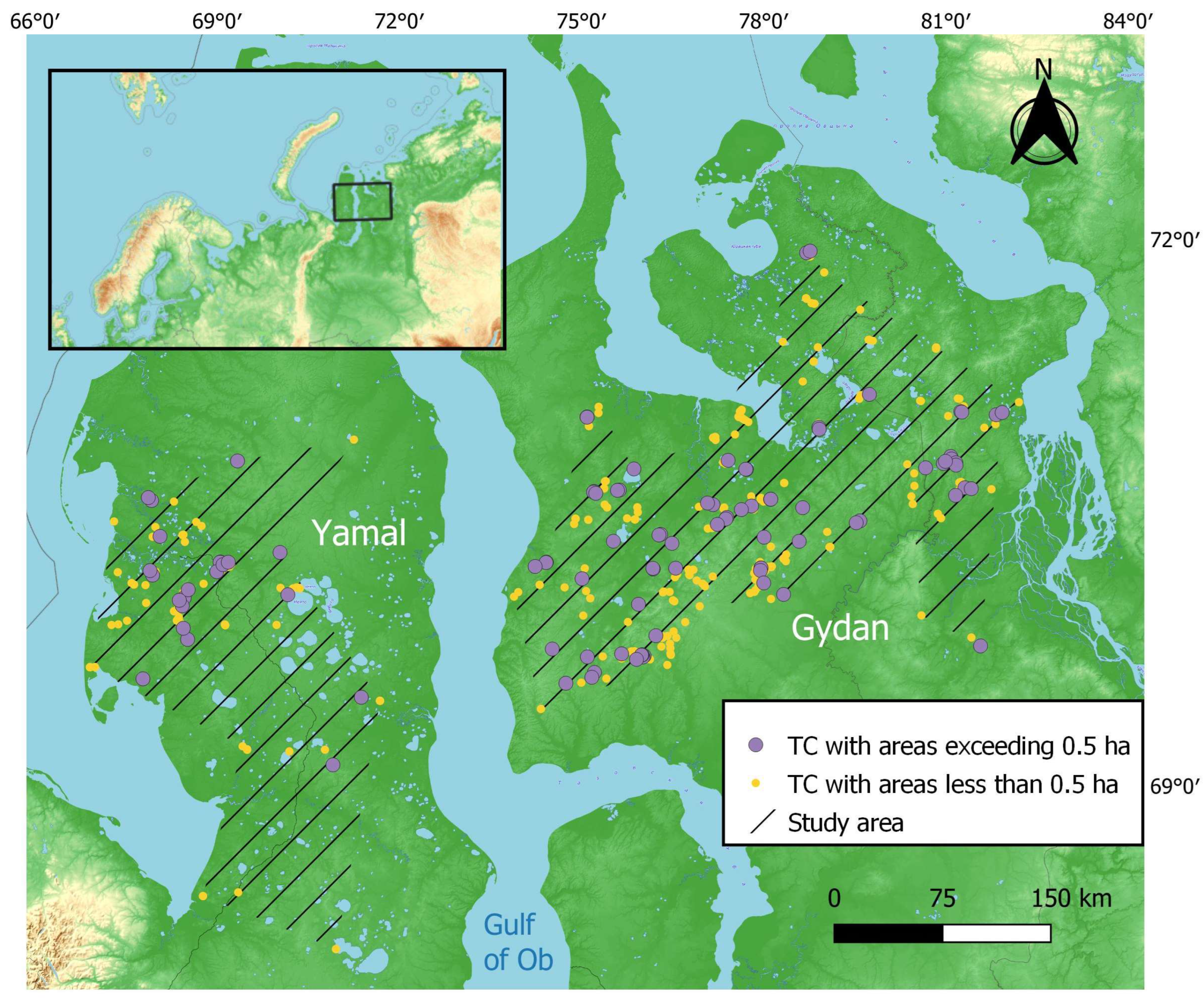
The study area is located north of West Siberia, a region with continuous ice-rich permafrost and a prevalence of tabular ground ice in the geological section that occurs very close to the surface [4,17,18,19]. At the same time, this area is a dissected lowland with long slopes composed of sandy–clayey deposits. The combination of these factors explains the domination of thermo-denudation over other cryogenic processes, such as thermokarst. The North of West Siberia is divided into two peninsulas, separated by an Ob river estuary and the Gulf of Ob: Yamal and Gydan (Figure 2). The area of the Yamal peninsula is smaller than that of Gydan. Dominating elevations, according to Russian topographic maps of Yamal, are less than 60 m with a maximum of 90 m, while elevations of Gydan exceed 100 m reaching a maximum of 191 m, all in the Baltic heights system.
Field data were collected at the research station Vaskiny Dachi in Central Yamal [13] at an area of about 100 km2.
The study covers a variety of scales, from regional to local. At a regional scale, we operate with TCs identified using Yandex.Maps, Sentinel 2, and analysis of ArcticDEM; at a local scale, we use very-high-resolution imagery, UAV orthophoto mosaic, and field surveys (Figure 1).
To estimate TC impact, study area polygons (Figure 2, hatching) were generated using a concave hull approach that calculates the region encompassing a set of points by employing k-nearest neighbors in QGIS.

2.1. Manual Digitization of TC Polygons

The location of each TC mapped in West Siberia as of 2016–2018 [14] was used for digitizing polygons of TCs on Sentinel-2A and Sentile-2B satellite images of 2021. The dataset contains 484 point objects of active and recently active (stabilized) TCs clearly identified visually. All of them were filtered by the visibility on Sentinel-2 satellite images (2021) having 10 m spatial resolution. The majority of Sentinel-2 images were dated September 2021; there were also some dated August and October [15].
The digitization of TC polygons was manually performed on the Google Earth Engine platform using visual signs. These signs are as follows: a specific crescent shape and a headwall of a TC clearly outlined by shade or snow and a gray color of thawed matter flow for active TCs. Visual signs of recently stabilized TCs are a clear boundary line of the former active TC and, at the same time, green color inside the TC in natural-color composite evidencing revegetation of the scar. Pronounced changes in the palette of pixels between the inside and the outside of a TC were considered. TCs usually have lighter tones of green or gray compared to adjacent undisturbed surfaces, depending on the characteristics of the territory. The contour of the edge connects points with a sharp color transition. In some cases, the object boundaries of interest were clearly visible. Those were especially distinguishable in large objects with an area of at least 2.5 ha. To increase visual perception, we sometimes reduced the scale from 1:5000 to 1:20,000. The primary attention was paid to color parameters due to the quality features of the satellite images. Lake shoreline was taken as a lower TC limit when debris tongue enters the lake, as shown in Figure 3.
The built-in functions for creating vector objects on the Google Earth Engine platform were used as the main tool in TC area delineation. The area of each created polygon was calculated via JavaScript. Figure 3 shows an example of TC area digitization.
The digital elevation model ArcticDEM 2016, which is freely available on the Google Earth Engine (GEE) cloud platform, was used in the work as a raster mosaic with a spatial resolution of 2 m [16]. Additionally, a mosaic of Sentinel-2 images for August 2016 (corresponding to the ArcticDEM date) [15] was used to visually interpret the boundaries of TCs. The data were obtained similarly to ArcticDEM in the Google Earth Engine catalog [20].

2.2. Accuracy Analysis

To test the accuracy of the manual TC area digitization method, we delineated TC areas on available very-high-resolution imagery (VHR) and compared them to the areas digitized on Sentinel-2. Thus, areas delineated on WorldView-2 satellite images for the Yamal key site (July 10, 2018) were compared to the areas digitized on July 2018 Sentinel-2 images. Similarly, areas based on WorldView-3 satellite images for the Gydan key site (17 July 2019 and 29 July 2019) were compared to areas delineated on available July 2019 Sentinel-2 satellite images.
In addition, to estimate the accuracy of area digitizing, we have compared the results with those digitized using a UAV survey at the Vaskiny Dachi research station in Central Yamal in 2021. UAV strip surveys with ground control points positioning (using GPS trackers) covered several TCs. The data of the survey were processed and resulted in orthophoto maps and digital elevation models. The resulting orthophoto map has a spatial resolution of approximately 0.02 m. The boundaries of each TC were drawn along the pronounced edge, and significant cracks separated half-fallen blocks.

2.3. Software

TC contour digitization was performed on the Google Earth Engine platform, a cloud geospatial processing service. UAV data were processed in Agisoft Metashape software (version 1.7.4). Geospatial processing was performed in QGIS (version 3.28.2-Firenze), and illustrations were created using Python (version 3.8.10).

3. Results

Distribution of TCs over the North of West Siberia differs between the Yamal and the Gydan peninsulas, changing northward and eastward. A noticeable disparity in distribution across the area can be seen in Figure 2, with Yamal displaying a particularly distinctive pattern. As follows from the map (Figure 2), the densest are TCs in the west of the Yamal and the west of the Gydan peninsulas, increasing in number from southeast to northwest on the Yamal peninsula and from northeast to southwest on Gydan. The northernmost TCs on Gydan are farther north compared to that on Yamal, while the southernmost TCs on Yamal are farther south compared to that on Gydan.

3.1. TC Area Measurement and Frequency Distribution

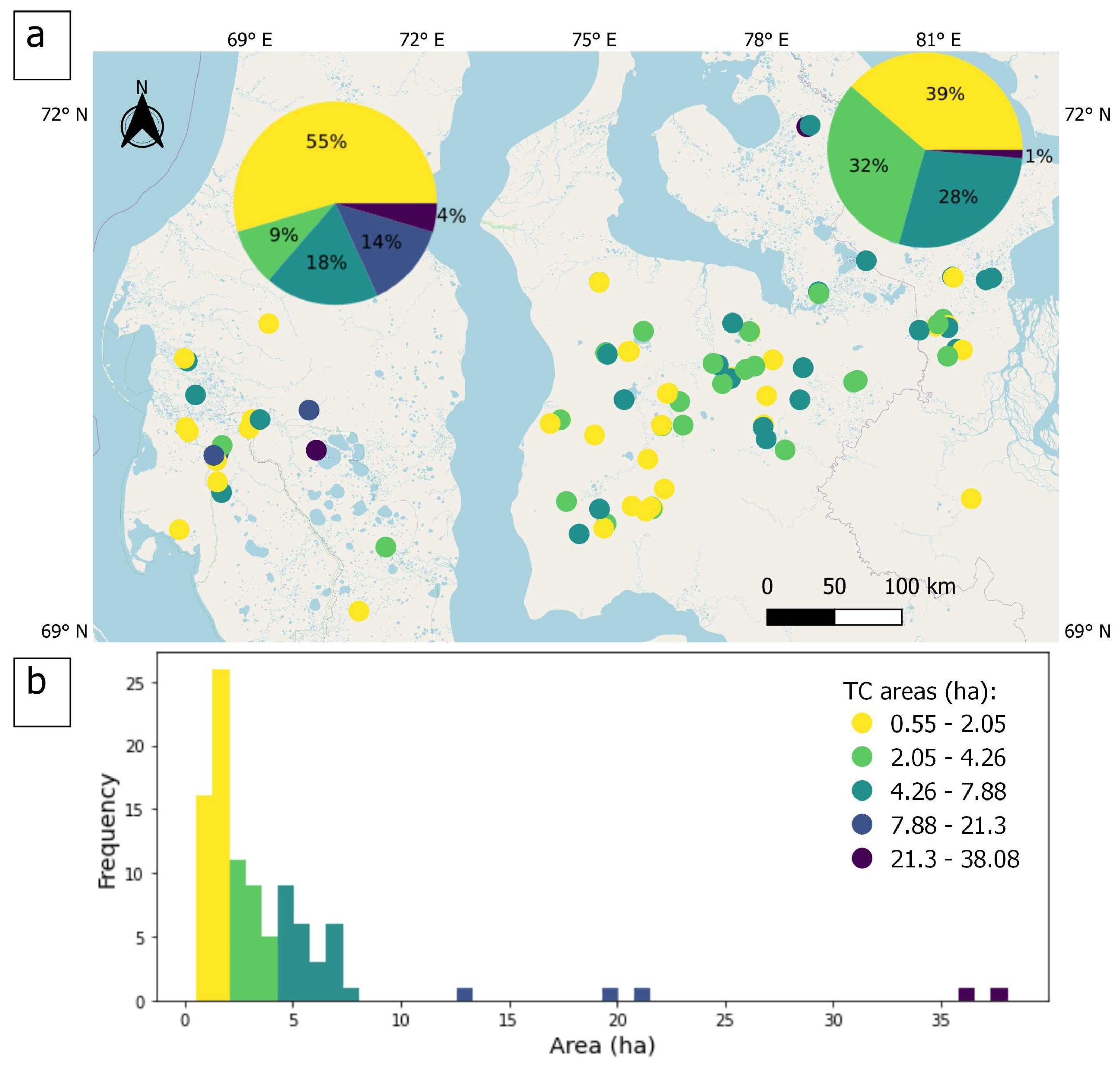
The dataset includes TCs having a wide range of area values. Only 161 active and stabilized TCs appeared to be distinguishable on the Sentinel-2 image with a large enough measurable area. The smallest TC visible has an area of 0.55 ha. Thus, the rest of the 323 TCs in the dataset for West Siberia have areas that are too small. The other particularity of interpreting TCs on Sentinel-2 is that 64 TCs from the dataset merged with the neighbors: 51 on Gydan and 13 on Yamal. The spatial distribution of TCs with measured areas is shown in Figure 4a. All TCs spread all over the central parts of the Yamal and Gydan peninsulas limited by the latitude 71°56′25″ in the North and 68°00′55″ in the South.
The frequency of the area distribution is presented in Figure 4b. The histogram shows that the TC area distribution is skewed to the lower values. Areas of less than 2.05 ha prevail in both Yamal and Gydan, but their proportions vary. In Yamal, an area of less than 2.05 ha accounts for about half of the objects, but in addition, valuable are other categories of areas: almost a third of TCs occupy areas of 2.05–7.88 ha, and large TCs with an area of more than 10 ha occupy a total of about 20%. At the same time, 99% of TCs in Gydan have an area of less than 7.88 ha: each range in this category represents about a third. Around 95% of TCs with measured dimensions have areas less than 10 ha, and 79% of the areas lie within the 1–2 ha range. The median area is 2.5 ha, and the mean area is 4 ha.
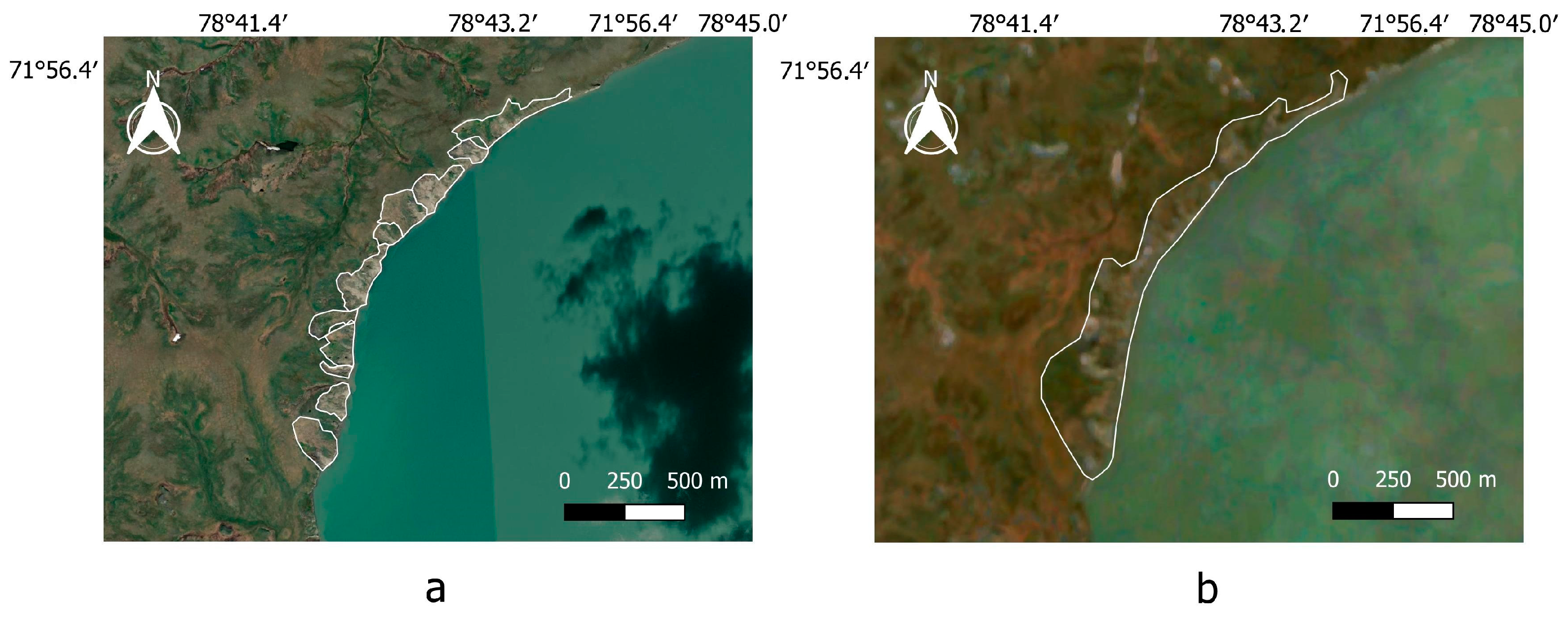
TCs with an area exceeding 8 ha comprise only 6% of the entire dataset. The largest TC, with an area of 38 ha, was found in the northern part of the Gydan peninsula. This TC gained such an area due to the merging of around 10 single small TCs on the lake shore, as can be noted on a very-high-resolution image QuickBird-2, 22 July 2005 ESRI basemap (Figure 5).
The first approximation of the TC distribution density in both the number of objects and the area of disturbance is shown in Table 1. The impact is calculated within the boundary enveloping the entire area of the TC occurrence in the North of West Siberia and separately for the Yamal and the Gydan peninsulas. Two types of impact were calculated: Impact N as the number of TCs per km2 and Impact A as an aggregated area of all TCs in km2 per km2. Total impact as an expanded version of Impact A was calculated approximately by adding a roughly estimated aggregated area of all small TCs to measured areas of larger TCs (Table 1).
Analysis of Table 1 shows that the density of TCs on the Gydan peninsula is higher than that on the Yamal peninsula, almost three times in number and twice in area. The total area of small TCs, though not measured but taken approximately as half of the maximum, is added to the calculation of impact and increases it by about 18.5% for the Yamal peninsula, by 21% for the Gydan peninsula, and by 19.8% for the total area of TC distribution in the North of West Siberia. The area of TC distribution includes river basins, lakes, and flat hilltops. This explains a relatively low impact of thermodenudation when calculated for the entire terrain.

3.2. TC Edge Elevation and Slope Angle

The TC edge can be located at any portion of the slope, closer to the watershed, or to the slope foot. This parameter ranges from 10.3 to 33.8 m on the Yamal peninsula and 2.9 to 65.6 m on the Gydan peninsula. The spatial distribution of this parameter is shown in Figure 6a. The median TC edge elevation for the entire dataset is 26 m, for the Yamal is 17.7 m, and for the Gydan peninsula 29.4 m. This pattern most likely results from the difference in dominating elevations of the surface, which are much higher on Gydan than on Yamal, as seen in the pie charts (Figure 6a).
The majority of TC edges are within the range of 13–52.4 m asl. Dominating are elevations of 13–26.3 m (40 objects, Figure 6b). A rather high number of objects falls into the categories 26.3–39.4 m (25 objects) and 39.4–52.4 m (15 objects) (Figure 6b). Extreme elevations are characteristic of less than 10 objects each.
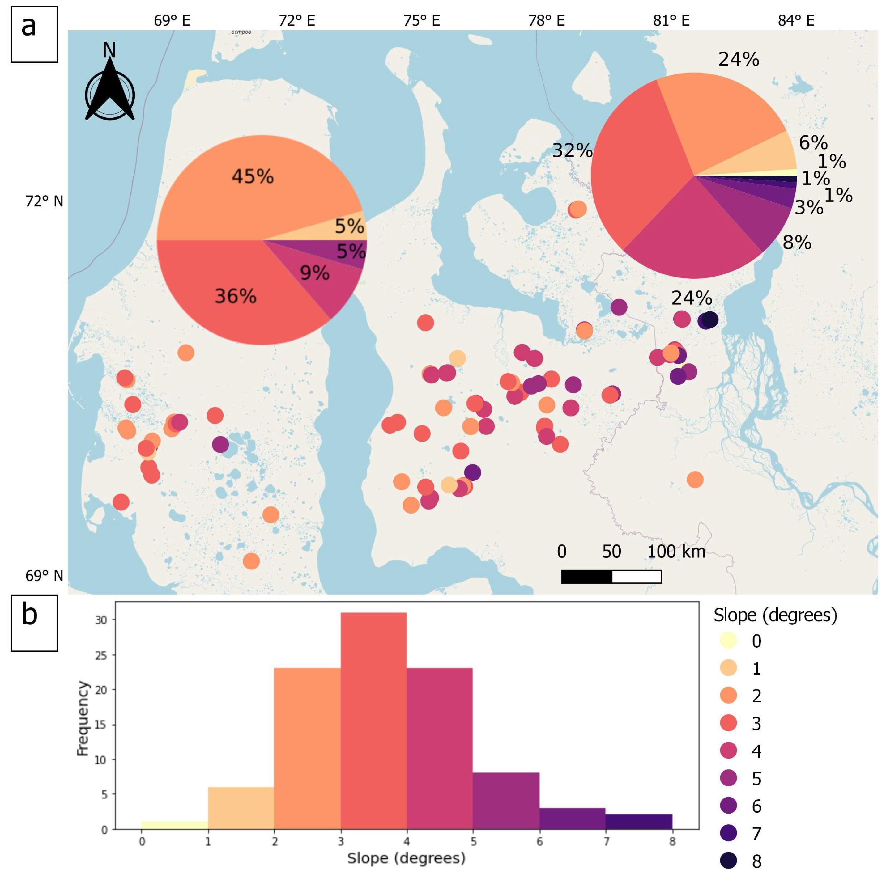
The slope angle was collected from the ArcticDEM as an inclination of an entire slope bearing a TC. The range of slopes subject to thermodenudation is rather narrow. Slopes of TC location are gentle from almost horizontal to a maximum of 8 degrees. The slope angle ranges from 1 to 5 degrees on the Yamal peninsula and 1 to 8 degrees on the Gydan peninsula. The median slope angle for the entire dataset is 3 degrees, separately for Yamal 2.5 degrees, and separately for Gydan 3 degrees (Figure 7a).
Dominating slope angles of about 3 degrees comprise 31 TC-bearing slopes (Figure 7b), less frequent are 2 and 4-degree slopes (24 cases each), rarest are extremes, 1 and 5–8 degrees (19 cases in total) (Figure 7b). TC-bearing slopes in Yamal have mostly angles of 2 or 3 degrees: 81% out of the total, while such slope angles in Gydan comprise slightly more than half, 56%. The steepest slope angle in Yamal is 5 degrees, while in Gydan, it reaches 8 degrees. Moreover, slope angles larger than 4 degrees represent more than a third of all TC-bearing slope angles in Gydan.

4. Discussion

4.1. Accuracy and Verification

TCs of different dimensions can be located at a variety of terrain elevations and slope angles. This information can be used to analyze geomorphic elements of the area, such as marine plains comprising the North of West Siberia, as presented in [13]. One of the possible applications of these results is the geospatial distribution of close-to-the-surface tabular ice bodies as the main control of TC formation. Statistics of the TC parameters with spatial distribution, as in Figure 4, Figure 6 and Figure 7, are presented in Table 2. Note that the Count parameter includes only TCs with measurable areas; the number in parentheses for this parameter refers to the merged objects.
The comparison of the manual TC area mapping based on Sentinel-2 (2018) satellite images with the same procedure based on the available WorldView-2 and 3 images (2018) for key sites showed a relative error of 1.55%. This result demonstrates a rather high reliability of the manual method of the TC area delineation using 10 m resolution imagery for relatively large TCs (>0.5 ha). Figure 8a displays measured area (in ha) and related inaccuracies (in m2) when compared to VHR satellite images. Since VHR satellite images are limited in coverage, only TCs that appear in the available images were used for verification. The results demonstrate that both underestimation (negative inaccuracy) and overestimation (positive inaccuracy) of the manual delineation method are present in relatively equal proportions. It can be noted that positive inaccuracy tends to have lower values than negative inaccuracy for both Yamal and Gydan. The majority of verification points available in the study region have area values less than 2 ha. Obviously, measuring larger TCs should result in even better accuracy. Only one TC located in Gydan with an area of around 5 ha was available for verification, and, as expected, it demonstrated relatively high accuracy. Thus, taking into account that verification was based on relatively small TCs, inaccuracy did not exceed 300 m2 (1.55%).
Verification analysis of the TC areas derived from Sentinel-2 (2021) showed a relative error of 5.05 % when compared with TC areas measured on UAV-based orthophoto plans. A comparison of measured areas with UAV orthophotos shows an equal proportion of overestimation and underestimation. Few TCs available for this comparison have relatively small measured areas and exhibit relatively high inaccuracy. This inaccuracy is related to a considerable difference in the spatial resolution of the imagery used. Sentinel-2 images with 10 m spatial resolution are 500 times coarser than orthophoto maps and, thus, provide significantly less detailed visual signs of a TC edge. Taking a 10 × 10 m2 pixel size, every 100 m of the TC outline may give an error up to 0.1 ha, so the larger the TC, the less weight of the outline in an area count.
Considering the manual nature of the work with the unavoidable chance of human error, the results seem fair.

4.2. Terrain Elevation Bias between ArcticDEM and Baltic Height System

The ArcticDEM digital elevation model is based on the WGS84 ellipsoid. Extensive multidisciplinary field studies in West Siberia undertaken since the 1950s operate with the Baltic height system, which is used to compile Russian State topographic maps. So far, there is no common digital elevation model in the Baltic height system covering the entire territory of the Russian Federation, which makes it impossible to transfer elevations to the entire study area. In some cases, artifacts in ArcticDEM are observed, such as 0–1 m elevations above sea level of the TC edge. Meanwhile, using ArcticDEM makes it easier to compare the results of the TC parameters analysis with foreign studies, which are carried out on the basis of the WGS84 elevation system.
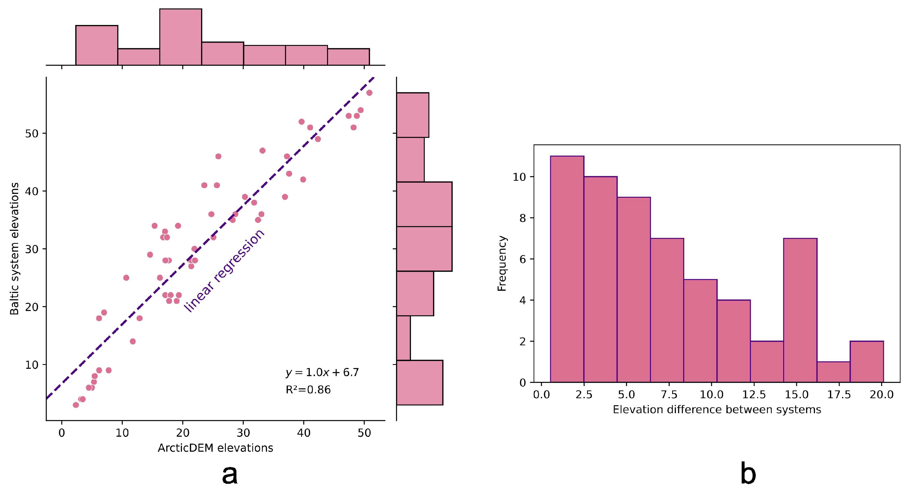
In a study by I.I. Tarasevich and others [19], the deviation measured by comparing ArcticDEM and Baltic-system topographic maps comprised approximately 10 m within a small area. In an unpublished study performed in the southernmost part of the study area, the deviation calculated was around 15 m. We performed a similar comparison of a topographic map in the Baltic height system and ArcticDEM for the selected area in central Yamal. To calculate possible bias, we compared 58 control points on a Russian topographic map through georeferencing to WGS84, with elevations on ArcticDEM in the same points. Elevation differences between ArcticDEM and the topographic map are presented in Figure 9. ArcticDEM elevations were subtracted from Baltic system elevations. The resulting positive values reflect an underestimation of heights in the model compared to ground truth.
Figure 9 demonstrates a strong correlation between two elevation sources, as evidenced by a linear regression with an R2 value of 0.86. The histogram of elevation differences illustrates a range from 0.53 to 20.11 and a gradual reduction of this difference frequency towards higher values. One peak value of frequency around 15 m difference probably is an artifact that is hard to explain logically.
Despite a strong relationship between different elevation systems, it is crucial to expand the comparison to the entire study area. This will enable us to align ArcticDEM with field data analysis and interpret the geomorphic position of geological sequences more accurately in the future.

4.3. Merging TCs and Resolution Limitations

Many TCs expand in width by merging with neighbors. The trend of existing TCs enlargement rather than new TC formation was also mentioned in the study in East Siberia [21].
Delineating and counting the edges of numerous merged TCs as separate features are only possible with high spatial resolution images. The same challenge has been reported for automated mapping of amalgamated landslides [22]. However, high-resolution satellite imagery is expensive, has limited coverage of cloudless frames, and its processing is time-consuming. At the same time, mapping adjacent features as one polygon can strongly affect the resulting values.

4.4. Comparison with Other Regions

The ranges of measured TC areas, in general, are consistent with previous recent findings of this parameter in other parts of the Arctic and Tibet.
The study in Bluenose Moraines, western Nunavut, Canada, used the same manual delineation method based on the same spatial resolution of 10 m of SPOT 5 and 4 satellite images. The majority of TC areas there (82 points) appeared to be smaller than 10 ha. The smallest recognizable TC was 0.7 ha [23]. The average TC area of 4 ha and the largest TC area of 38 ha found in West Siberia are comparable with the results for Bluenose Moraines, with 5.6 ha and 40 ha, respectively. Other studies that use higher resolution input data report 832 TCs from 0.02 ha to 22.4 ha (with an average of 1.7 ha) for the eastern Banks Island, Northwest Territories, and Canada [24]. Other research estimations of TC areas for Banks Island, Canada, were 1.63 ± 0.23 ha for 2015 [25]. A total of 160 TCs with areas smaller than 1 ha and up to 5 ha (with a median size of 0.4 ha) were reported for Tuktoyaktuk coastlands [26]. More than 60 TCs with a majority of area values less than 2 ha, and the largest one up to 40 ha were measured in Stony Creek, Peel Plateau, Canada [27]; and 287 TCs (slumps) within the Yukon coast, Canada, were measured using high-resolution satellite images, showing the median size of 0.24 ha [28].
For the Alaska region, 22 TCs (slumps) were studied, and areas reported were in the range from 0.6 ha to 5.2 ha in Noatak Valley [29].
Areas calculated based on Landsat images for North-Eastern Siberia, Russia, were reported to be between 1.4 ha (Chukordakh) and 4.8 ha (Chukotka) [21].
Several recent studies estimated TC areas in the Tibet region in China. The largest TC in the Qinghai–Tibet Engineering Corridor was found to have an area of 24.03 ha, and the smallest one was 0.05 ha; the majority of areas were smaller than 10 ha [30]. Two studies from the Beiluhe region reported TC areas in the range from 0.3 to 35.2 ha with a mean value of 2–3.5 ha; the majority of the areas were found to be less than 8 ha [31,32].
The comparison of measured areas with the results of other researchers is challenging due to a certain ambiguity regarding the inclusion of stabilized parts of TCs in the area measurements. Moreover, manual delineation leads to some degree of subjectivity.
The studies mentioned above do not present an estimation of the accuracy of TC area delineation. Therefore, it is difficult to compare the performance of our results. However, we present not only the TC areas measured but also the verification method used, which can serve as a valuable reference for future studies.

5. Conclusions

To summarize, several aspects of the presented research are highlighted:
  • A total of 95% of the TC areas are smaller than 10 ha, with the smallest TC identifiable if its area is at least 0.5 ha and the largest found to be 38 ha;
  • Many TCs in the region appear to have expanded in width due to merging with neighboring ones when identified on 10 m resolution imagery;
  • While the majority of TC areas are small in both peninsulas, there still is a clear difference in area distribution between the two. All frequency ranges of TC area values in the Yamal peninsula are distributed more or less evenly except the smallest, while 99% of TCs in Gydan had an area of less than 7.88 ha;
  • The edge elevations of TCs are expectedly different for both peninsulas, with Gydan having higher relief elevations in general and, thus, higher position of TC edges;
  • The slope angles of TC-bearing slopes on Gydan are found to be slightly steeper than those on Yamal. However, in general, TC-bearing slopes on both peninsulas are gentle, with angles of no more than 8 degrees;
  • Accuracy analysis revealed a relative error of 1.55% when comparing TC areas with those delineated on very-high-resolution satellite images and up to 5.05% when compared to UAV-based orthophotos;
  • Comparison of ArcticDEM elevations with those from a topographic map based on the Baltic height system that can be considered as “ground truth” demonstrates a clear bias and the need for adjustment throughout the region to compare contemporary results with prior knowledge on the relief and permafrost of West Siberia;
  • The results obtained are comparable with those for North America and China when the same method and input data quality are used.
This research is the first step to understanding the morphological characteristics of the TCs in West Siberia. We plan to focus further studies on other parameters, such as the relation of TC distribution and size to slope elevation and aspect.

Author Contributions

Conceptualization, N.N. and M.L.; methodology, N.N. and M.A.; software, M.A. and N.N.; validation, N.N. and M.A.; formal analysis, M.L. and N.N.; data curation, M.A.; writing—original draft preparation, M.L.; writing—review and editing, N.N.; visualization, N.N.; supervision, M.L.; project administration, M.L.; funding acquisition, M.L. All authors have read and agreed to the published version of the manuscript.

Funding

The research was funded by the Russian Science Foundation, grant number No. 22-27-00644.

Data Availability Statement

Not applicable.

Conflicts of Interest

The authors declare no conflict of interest.

References

  1. Are, F.E. Thermoabrasion of the Arctic Coasts; Nauka Publisher: Moscow, Russia, 1980. [Google Scholar]
  2. Kaplina, T.N. Cryogenic Slope Processes; Nauka Publisher: Moscow, Russia, 1965. [Google Scholar]
  3. Zhigarev, L.A. Termodenudation Processes and Deformation Behavior of the Thawing Ground; Nauka Publisher: Moscow, Russia, 1975. [Google Scholar]
  4. Leibman, M.O.; Kizyakov, A.I. Cryogenic Landslides of the Yamal and Yugorsky Peninsulas; The Earth Cryosphere Institute: Moscow-Tyumen, Russia, 2007. [Google Scholar]
  5. Mackay, J.R. Segregated Epigenetic Ice and Slumps in Permafrost, Mackenzie Delta Area, NWT. Geogr. Bull. 1966, 8, 59–80. [Google Scholar]
  6. Burn, C.R.; Friele, P.A. Geomorphology, vegetation succession, soil characteristics and permafrost in retrogressive thaw slumps near Mayo, Yukon Territory. Arctic 1989, 42, 31–40. [Google Scholar] [CrossRef]
  7. Lewkowicz, A.G. Headwall retreat of ground-ice slumps, Banks Island, Northwest Territories. Can. J. Earth Sci. 1987, 24, 1077–1085. [Google Scholar] [CrossRef]
  8. Burn, C.R.; Lewkowicz, A.G. Canadian landform examples—17 retrogressive thaw slumps. Can. Geogr./Le Géogr. Can. 1990, 34, 273–276. [Google Scholar] [CrossRef]
  9. Kokelj, S.V.; Lewkowicz, A.G. Salinization of permafrost terrain due to natural geomorphic disturbance, Fosheim Peninsula, Ellesmere Island. Arctic 1999, 52, 372–385. [Google Scholar] [CrossRef] [Green Version]
  10. Mesquita, P.S.; Wrona, F.J.; Prowse, T.D. Effects of retrogressive permafrost thaw slumping on sediment chemistry and submerged macrophytes in Arctic tundra lakes. Freshw. Biol. 2010, 55, 2347–2358. [Google Scholar] [CrossRef]
  11. Malone, L.; Lacelle, D.; Kokelj, S.; Clark, I.D. Impacts of hillslope thaw slumps on the geochemistry of permafrost catchments (Stony Creek Watershed, NWT, Canada). Chem. Geol. 2013, 356, 38–49. [Google Scholar] [CrossRef]
  12. Leibman, M.; Khomutov, A.; Kizyakov, A. Cryogenic landslides in the West-Siberian plain of Russia: Classification, mechanisms, and landforms. In Landslides in Cold Regions in the Context of Climate Change, Environmental Science and Engineering; Shan, W., Guo, Y., Wang, F., Marui, H., Strom, A., Eds.; Springer International Publishing: Cham, Switzerland, 2014; pp. 143–162. [Google Scholar] [CrossRef]
  13. Khomutov, A.; Leibman, M.; Dvornikov, Y.; Gubarkov, A.; Mullanurov, D.; Khairullin, R. Activation of Cryogenic Earth Flows and Formation of Thermocirques on Central Yamal as a Result of Climate Fluctuations. In Advancing Culture of Living with Landslides. Proceedings of the World Landslide Forum 4, Ljubljana, Slovenia, 29 May–2 June 2017; Landslides in Different Environments; Mikoš, K., Vilímek, V., Yin, Y., Sassa, K., Eds.; Springer International Publishing AG: Ljubljana, Slovenia, 2017; Volume 5, pp. 209–216. [Google Scholar]
  14. Nesterova, N.B.; Khomutov, A.V.; Leibman, M.O.; Safonov, T.A.; Belova, N.G. The Inventory of Retrogressive Thaw Slumps (Thermocirques) in the North of West Siberia Based on 2016–2018 Satellite Imagery Mosaic. Earth’s Cryosphere 2021, 25, 41–50. [Google Scholar] [CrossRef]
  15. The Sentinel-2 Data. Available online: https://developers.google.com/earth-engine/datasets/catalog/COPERNICUS_S2 (accessed on 11 November 2022).
  16. Claire, P.; Paul, M.; Ian, H.; Myoung-Jon, N.; Brian, B.; Kenneth, P.; Scott, K.; Matthew, S.; Judith, G.; Karen, T.; et al. ArcticDEM, Version 3; Harvard Dataverse: Cambridge, MA, USA, 2018. [Google Scholar] [CrossRef]
  17. Baulin, V.V.; Belopukhova, E.B.; Dubikov, G.I.; Shmelev, L.M. Geocryological Conditions of West Siberian Lowland; Nauka Publisher: Moscow, Russia, 1967. [Google Scholar]
  18. Belova, N.G.; Solomatin, V.I.; Noskov, A.I.; Ogorodov, S.A. Ural coast of Baydaratskaya bay, Kara Sea: Massive ice beds as a factor of coastal dynamics. In Reports on Polar and Marine Research; Alfred Wegener Institute: Bremerhaven, Germany, 2018; Volume 576, pp. 44–46. [Google Scholar]
  19. ArcticDEM Mosaic. Available online: https://developers.google.com/earth-engine/datasets/catalog/UMN_PGC_ArcticDEM_V3_2m_mosaic (accessed on 11 November 2022).
  20. Tarasevich, I.I.; Kizyakov, A.I.; Leibman, M.O.; Pismenyuk, A.A.; Nesterova, N.B.; Khairullin, R.R.; Khomutov, A.V. Dynamics of thermodenudation in the Central Yamal in 2017–2021 based on the annual monitoring. In Relief and Quaternary Formation of the Arctic, Sub-Arctic and North-West of Russia. Materials of Annual Conference on the Results of Field Studies; AARI Publisher: St-Petersburg, Russia, 2022; Volume 9, pp. 253–257. [Google Scholar]
  21. Runge, A.; Nitze, I.; Grosse, G. Remote sensing annual dynamics of rapid permafrost thaw disturbances with LandTrendr. Remote Sens. Environ. 2022, 268, 112752. [Google Scholar] [CrossRef]
  22. Marc, O.; Hovius, N. Amalgamation in landslide maps: Effects and automatic detection. Nat. Hazards Earth Syst. Sci. 2015, 15, 723–733. [Google Scholar] [CrossRef] [Green Version]
  23. Segal, R.A.; Lantz, T.C.; Kokelj, S.V. NWT Open Report 2015-023 Inventory of Active Retrogressive Thaw Slumps in the Bluenose Moraine, Western Nunavut; Government of Northwest Territories: Yellowknife, NT, Canada, 2016.
  24. Segal, R.A.; Lantz, T.C.; Kokelj, S.V. NWT Open Report 2015-021 Inventory of Active Retrogressive Thaw Slumps on Eastern Banks Island, Northwest Territories NWT Open Report 2015-021; Government of Northwest Territories: Yellowknife, NT, Canada, 2016.
  25. Lewkowicz, A.G.; Way, R.G. Extremes of summer climate trigger thousands of thermokarst landslides in a High Arctic environment. Nat. Commun. 2019, 10, 1329. [Google Scholar] [CrossRef] [PubMed] [Green Version]
  26. Zwieback, S.; Kokelj, S.; Günther, F.; Boike, J.; Grosse, G.; Hajnsek, I. Sub-seasonal thaw slump mass wasting is not consistently energy limited at the landscape scale. Cryosphere 2018, 12, 549–564. [Google Scholar] [CrossRef] [Green Version]
  27. Kokelj, S.V.; Lacelle, D.; Lantz, T.C.; Tunnicliffe, J.; Malone, L.; Clark, I.D.; Chin, K.S. Thawing of massive ground ice in mega slumps drives increases in stream sediment and solute flux across a range of watershed scales. J. Geophys. Res. Earth Surf. 2013, 118, 681–692. [Google Scholar] [CrossRef]
  28. Ramage, J.L.; Irrgang, A.M.; Herzschuh, U.; Morgenstern, A.; Couture, N.; Lantuit, H. Terrain controls on the occurrence of coastal retrogressive thaw slumps along the Yukon coast, Canada. J. Geophys. Res. Earth Surf. 2017, 122, 1619–1634. [Google Scholar] [CrossRef]
  29. Swanson, D.K.; Nolan, M. Growth of retrogressive thaw slumps in the Noatak Valley, Alaska, 2010–2016, measured by airborne photogrammetry. Remote Sens. 2018, 10, 983. [Google Scholar] [CrossRef] [Green Version]
  30. Xia, Z.; Huang, L.; Fan, C.; Jia, S.; Lin, Z.; Liu, L.; Luo, J.; Niu, F.; Zhang, T. Retrogressive thaw slumps along the Qinghai–Tibet Engineering Corridor: A comprehensive inventory and their distribution characteristics. Earth Syst. Sci. Data. 2022, 14, 3875–3887. [Google Scholar] [CrossRef]
  31. Luo, J.; Niu, F.; Lin, Z.; Liu, M.; Yin, G. Recent acceleration of thaw slumping in permafrost terrain of Qinghai-Tibet Plateau: An Example from the Beiluhe Region. Geomorphology 2019, 341, 79–85. [Google Scholar] [CrossRef]
  32. Huang, L.; Luo, J.; Lin, Z.; Niu, F.; Liu, L. Using deep learning to map retrogressive thaw slumps in the Beiluhe region (Tibetan Plateau) from CubeSat Images. Remote Sens. Environ. 2020, 237, 111534. [Google Scholar] [CrossRef]
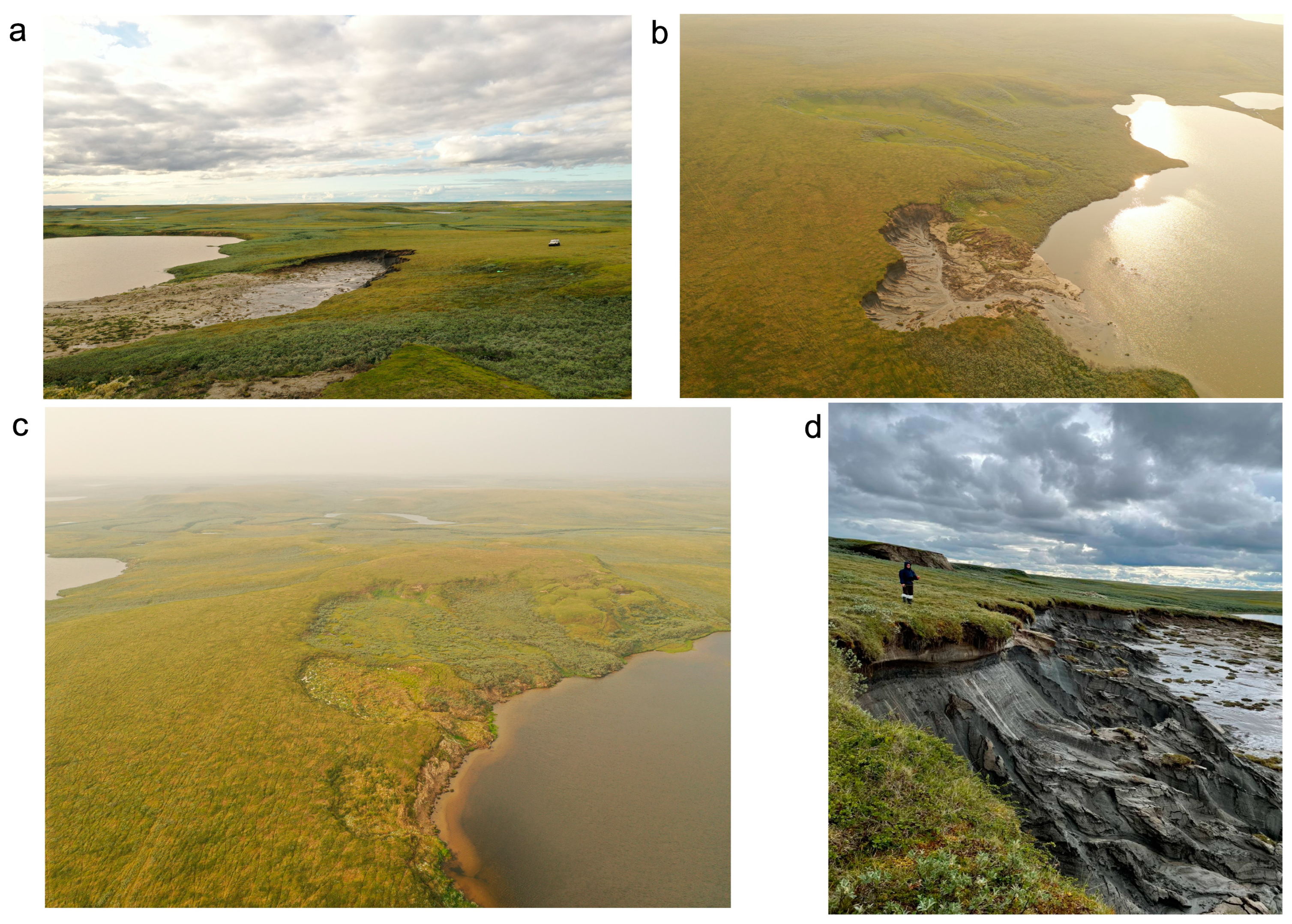
Figure 1. Field photos in Yamal key site: (a) Unmanned Aerial Vehicle (UAV) photo of an active TC, the white vehicle on the right as a scale; (b) UAV photo of an active TC, mudflow ends up in the lake; (c) UAV photo of stabilized TCs with clearly seen edge and partly revegetated scar; (d) Field photo of retreating ice-bearing headwall in a TC; (the UAV piloting and field photo by Nina Nesterova).
Geosciences 13 00167 g001
Figure 2. Study area with locations of TCs from the expanded dataset [14]. Projection: WGS 84. Basemap: OpenStreetMap contributors (2015) licensed under the Open Data Commons Open Database License (ODbL) by the OpenStreetMap Foundation (OSMF). Planet dump https://planet.openstreetmap.org (accessed on 30 March 2023).
Geosciences 13 00167 g002
Figure 3. An example of a TC appearance: (a) shown on ESRI basemap imagery (WorldView-3, 3 July 2016); (b) on Sentinel-2A 2021; (c) on Sentinel-2A 2021 with area digitized.
Geosciences 13 00167 g003
Figure 4. Spatial distribution (a) and frequency distribution (b) of a TC area in the North of West Siberia. Pie charts represent the proportion of TC areas for the Yamal and Gydan peninsulas separately. Projection: WGS 84. Basemap: OpenStreetMap contributors (2015) licensed under the Open Data Commons Open Database License (ODbL) by the OpenStreetMap Foundation (OSMF). Planet dump https://planet.openstreetmap.org (accessed on 30 March 2023).
Geosciences 13 00167 g004
Figure 5. The largest TC area is due to the merging of 10 small TCs in northern Gydan: (a) on ESRI basemap imagery (QuickBird-2, 22 July 2005); (b) on Sentinel-2B 2021 with area digitized.
Geosciences 13 00167 g005
Figure 6. Spatial distribution (a) and frequency distribution (b) of the TC edge elevation (m above sea level) in the North of West Siberia. Pie charts represent the proportion of TC elevations for the Yamal peninsula and Gydan peninsula separately. Projection: WGS 84. Basemap: OpenStreetMap contributors (2015) licensed under the Open Data Commons Open Database License (ODbL) by the OpenStreetMap Foundation (OSMF). Planet dump https://planet.openstreetmap.org (accessed on 30 March 2023).
Geosciences 13 00167 g006
Figure 7. Spatial distribution (a) and frequency distribution (b) of the TC-bearing slope angle (degrees) in the North of West Siberia. Pie charts represent the proportion of slope angles for the Yamal peninsula and the Gydan peninsula separately. Projection: WGS 84. Basemap: OpenStreetMap contributors (2015) licensed under the Open Data Commons Open Database License (ODbL) by the OpenStreetMap Foundation (OSMF). Planet dump https://planet.openstreetmap.org (accessed on 30 March 2023).
Geosciences 13 00167 g007
Figure 8. The TC area measured on Sentinel 2 compared to very-high-resolution (VHR) satellite images (a) and UAV orthophotos (b).
Geosciences 13 00167 g008
Figure 9. Differences between Baltic and ArcticDEM elevations in the sample area of Central Yamal in the North of West Siberia: (a) a scatterplot with fitted linear regression line and side histograms for each parameter; (b) a histogram of the frequency distribution of differences.
Geosciences 13 00167 g009
Table 1. The thermocirque (TC) impact within the North of West Siberia, affected area on Yamal and Gydan separately, and the North of West Siberia in total.
ParameterYamalGydanTotal
Area of TC distribution 1, km233,38440,37673,760
Number of TCs 2124360484
Impact N: TCs number per km24 × 10−39 × 10−36.5 × 10−3
Aggregated areas of TCs 3, km21.322.704.02
Impact A: TCs area per km23.89 × 10−56.69 × 10−55.45 × 10−5
Aggregated areas of small TCs 4, km20.220.580.8
Total impact: TCs area per km24.61 × 10−58.12 × 10−56.53 × 10−5
1 Area enclosed in the polygon shown on the map, Figure 2 (hatching). 2 Total number of TCs in the dataset (484 objects). 3 Only TCs with a measured area (161 objects). 4 All TCs, areas of small objects averaged at 0.0025 km2.
Table 2. Statistics of TC parameters (See Figure 4, Figure 6 and Figure 7), minimum, maximum, average, and median values for Yamal and Gydan peninsulas.
ParameterArea, haEdge Elevation, m aslSlope Angle, Degree
YamalGydanYamalGydanYamalGydan
Min0.60.5510.32.911
Max35.938.133.865.658
Average63.619.530.32.63.4
Median1.82.617.729.42.53
Count 135 (22)126 (75)35 (22)126 (75)35 (22)126 (75)
1 Number of TCs having measurable area, single (merged).
Disclaimer/Publisher’s Note: The statements, opinions and data contained in all publications are solely those of the individual author(s) and contributor(s) and not of MDPI and/or the editor(s). MDPI and/or the editor(s) disclaim responsibility for any injury to people or property resulting from any ideas, methods, instructions or products referred to in the content.