Article

A Sustainable Option to Reuse Scaly Clays as Geomaterial for Earthworks

Department of Engineering, University of Palermo, 90128 Palermo, Italy
*
Authors to whom correspondence should be addressed.
Geosciences 2024, 14(1), 17; https://doi.org/10.3390/geosciences14010017
Submission received: 30 October 2023 / Revised: 24 December 2023 / Accepted: 3 January 2024 / Published: 5 January 2024
(This article belongs to the Section Geomechanics)

Abstract

:
Scaly clays are structurally complex clay formations found throughout the world. Their typical fissured structure, the low shear strength and the high swelling potential often make them unsuitable for earthworks in road and railway infrastructure. This research has attempted to extend the possibilities of using this geomaterial in this field after appropriate lime treatment. A laboratory test programme was carried out to evaluate the response of the treated geomaterial to typical loads acting on road infrastructures. Unconfined and confined compression tests as well as cyclic triaxial tests, in undrained conditions, were carried out to investigate the static and dynamic mechanical behaviour. The results show that lime treatment induces significant improvements in the geomechanical properties and limits the swelling behaviour upon saturation of the geomaterial. Dynamic tests showed that, after only 28 days of curing, the treated scaly clay became insensitive to the damaging cyclic loading caused by vehicular traffic. The collected results show that the scaly clay can be properly used as a subgrade and embankment layer in road and railway construction with limited economic and environmental costs, after accurate treatment with lime. These results are significant for researchers and practitioners to increase sustainability in the construction of linear infrastructures involving excavations in scaly clays and to avoid landfill, which in some cases represented the only option.

1. Introduction

Scaly clays belong to structurally complex clayey formations widespread along the Italian Apennine Mountains and in many other parts of the world [1,2,3,4]. Despite their different geologic origins and mineralogical compositions, these soils share the complexity of processes (e.g., tectonics) that determined their current emplacement and distinctive geotechnical characteristics resulting from the intense geological history. In natural conditions, scaly clays are subdivided into small stiff clayey fragments (named scales) by a thick network of discontinuities and fissures. The material fabric plays a fundamental role in the hydraulic and mechanical behaviour of the deposits at different scales [5]. In saturated conditions, they are characterised by very poor mechanical properties. In fact, when they outcrop along gentle slopes, they are prone to triggering landslides [6,7]. The reasons for this susceptibility to landslides are the strain localisation along the pre-existing fissures and the low shear strength—close to the residual one—at the inter-scale level (i.e., at the contact between scales [8]) due to the iso-orientation of the clayey particles within the scales. Compaction erases the original oriented fissured structure, making it randomised [9]. However, stiffer scales survive dynamic or static efforts and play a fundamental role in the hydro-mechanical response of compacted scaly clays [9,10].
Scaly clays have been efficaciously used as a construction material for waste dam liners and earth dam cores. In these applications, the high confining stress acting on the clayey mass constrained the high swelling behaviour upon saturation, which characterises this compacted geomaterial, and enables sufficient strength and low water conductivity. Otherwise, compacted scaly clays have never been used for road and railway embankments because they do not have sufficient strength for external loads, their hydro-mechanical behaviour suffers significantly from the change in water content and suction, and they experience a high swelling tendency when they are subjected to saturation at low confining stress [10]. In this context, it could be useful to evaluate the possibility of applying the lime treatment on scaly clays to improve their hydro-mechanical properties and, consequently, to widen their application fields following the principles of sustainability in the engineering of construction materials. In fact, from the perspective of sustainable development, lime treatment of fine-grained soils is among the main measures of environmental protection: it fully meets the principles of minimising the use of non-renewable material resources and maximising the reuse of natural resources for the construction of civil engineering works [11], such as earthworks, avoiding landfill disposal.
As is known from the literature, the physicochemical process induced by lime treatment occurs in both the short and long term, simultaneously but on a different time scale: the short-term effects are almost instantaneous [12]; the long-term ones are slow and highly dependent on curing time [13,14,15]. Flocculation of clay particles, i.e., replacement of K+ and Na+ ions by Ca2+ ions, is a peculiarity of the short-term effects [16,17]. This results in a change in the apparent soil grain size and a reduction in the plasticity index. The long-term effects are manifested by pozzolanic reactions that generate stable compounds, such as calcium-silicate-hydrates (CSH), calcium-alumina-silicate-hydrates (CASH) and calcium-alumina-hydrates (CAH) [18,19,20]. Otherwise, the carbonation of unreacted lime and pozzolanic products adversely affects the long-term mechanical response [21,22,23]. The effects of lime treatment on unstructured clayey soil with regards to the microstructure, stiffness, shear strength, permeability and durability have been deeply investigated by the pioneering works [14,24,25] and by recent increasingly detailed research [26,27,28,29,30,31,32,33]. However, due to the scale effect of the stabilisation technique, there is a need to test the in situ behaviour of the treated geomaterials employing experimental test embankments [34]. To the best of the authors’ knowledge, there is still no extensive and clear experimental evidence on the effectiveness of treating structurally complex clayey soils, such as scaly clays, which are typically not considered for reuse in embankment construction when available from earthworks.
Therefore, in this paper, the efficiency of lime treatment on scaly clay is evaluated by means of a comprehensive experimental laboratory programme conducted to apply a variety of stress paths representative of the stress state of the different parts of a road embankment. Indeed, the laboratory plan carried out is much broader than those typically carried out for a mixture design of lime-treated soils for road construction: Firstly, the affinity between lime and clay was investigated, and the compaction characteristics were addressed. Then, both unconfined and confined compression tests were carried out in undrained conditions in order to quantify the mechanical improvement in static and dynamic conditions. To simulate the positions of different layers within the embankment, confined compression tests were carried out varying the confining pressure using triaxial cells operating in both monotonic and cyclic conditions. The results obtained are of great interest in the field of soil improvements since scaly clays are not typically considered for lime treatment, but they are regularly disposed of in landfills, accompanied by severe environmental issues when large volumes are involved in excavation works, as is the case during the construction of linear infrastructures.

2. Materials and Methods

Considering the main aim of this research, the experimental plan focused on evaluating the behaviour of the lime-stabilised scaly clay under a variety of stress paths representative of the stress state of the different parts of a road embankment. For this purpose, the laboratory tests were conducted according to the details provided in Table 1.
The investigated material is a scaly clay outcropping close to Palermo in Sicily (Italy). This geomaterial has been previously used as dam core material only, although it is very easy to find in Sicily, as an outcropping formation during the construction of linear infrastructures such as roads and railways.
The geotechnical properties of the tested soil are listed in Table 2. Based on its Atterberg limits, the scaly clay studied is characterised by a plasticity index, PI = wlwp = 36%, which is well above the minimum requirement lime treatment suitability criteria for this parameter [35]. The X-ray diffraction analysis conducted with Philips PW 1729 (model RX) on the powdered clay (passing through a 75 μm sieve) showed that scaly clay is mainly composed of kaolinite, illite and mixed layers (montmorillonite), while a limited amount of calcite and quartz can also be identified.
As previously mentioned, in its natural emplacement, the scaly clay is characterised by clayey aggregates (named scales): these aggregates have dimensions from a few millimetres to centimetres and can be easily reduced in dimension with a rubber pestle and limited manual force. The fraction passing through a No. 4 ASTM sieve (d = 4.75 mm)—composed of scales, fragments of scales and powdered clay—was selected for the experiments. Higher dimensions were considered in previous works on field tests on the treatment of clayey soils in embankments [36].
According to the data reported in Table 3, the lime selected for the treatment of the scaly clay is quicklime (CL 90Q, as stated by EN Standard 459-1) [37] with high water reactivity and fineness of grinding (category 1), in line with the requirements for use in road construction [38,39]. To limit the environmental and economic costs related to lime consumption, the maximum lime content investigated in this work was set as equal to 6%.
Preliminary tests, such as Atterberg limits and pH determinations, were carried out on the powdered clay (passing through a 0.425 mm sieve) mixed with different percentages of lime in dry weight. The compaction properties and standard bearing capacity (California Bearing Ratio, CBR) of the different mixtures were investigated by varying the initial water content and the lime content. Considering a possible use for embankment layers, Proctor Standard Energy (E = 594 kJ/m3) was applied on untreated and treated clays. Once the Proctor Standard optimum conditions were determined, static compaction was considered as the specimen preparation technique. The optimum conditions in terms of the water content and dry unit weight were then replicated in the test specimens, using a specific mould for each test in the experimental programme detailed in Table 1.
A comprehensive experimental programme, including unconfined and confined compression tests both in static and dynamic conditions, was carried out. Saturation tests were also carried out in laterally confined conditions, i.e., in the 1D condition, to evaluate the swelling behaviour of lime–clay mixtures. In this case, an oedometric cell with a diameter d = 56 mm and a height h = 20 mm was used, and a total vertical stress σv = 10 kPa was applied to the specimens. Water content and volume measurements carried out at the end of the tests proved that the completed saturation was always achieved.
A 50 kN loading frame, equipped with a triaxial cell for cylindrical soil specimens with d = 38 mm and h = 76 mm, was used to perform both the unconfined and the confined compression tests. For the case of confined compression tests, the specimens were laterally wrapped with an impermeable membrane, and vertical drainage was not allowed. Then, the confining pressure was applied in an undrained condition, and, after a few minutes, the failure stage started. For the case of the unconfined compression tests, the specimens were not included in the triaxial cell, and they were tested directly in the loading frame. All these tests were conducted with a constant axial strain rate set at 0.2%/min to ensure quick and undrained failure. A 10 kN load cell and a ±10 mm LVDT transducer measured the axial load and the axial displacement, respectively, during the failure stage.
A triaxial testing apparatus for soil specimens with d = 70 mm and h = 140 mm was used to evaluate the response to dynamic solicitations. The adopted apparatus includes a two-column reaction frame (maximum load 100 kN) equipped with a triaxial cell, a dynamic controller able to manage the closed-loop axes of the axial load, cell and back pressure with a maximum rate of 10 kHz, an electro-pneumatic actuator, a 24 kN submergible load cell and three LVDTs located outside the triaxial cell for axial strain measurements (one ±25 mm and two ±2.5 mm for dynamic measurements). Repeated dynamic cyclic tests were conducted to determine the resilient modulus Mr, simulating the stress state of the material subjected to moving wheel loads. The transit of a vehicle results in an impulsive increase in the deviatoric stress q = σ 1 σ 3 (where σ 1 is the axial stress and σ 3 is the confining stress). During the test, the specimen was subjected to dynamic axial stress and static confining stress. As shown in Figure 1, the tests were performed by applying a pulsating (duration equal to 0.1 s), cyclically repeated (period equal to 1 s) deviatoric stress increment ∆qcyclic at a constant confining pressure σ3 on the specimens. An axial contact stress (qc = 0.1 ∆qmax) was applied to keep positive contact between the specimen and the loading cap. After a certain number of load repetitions, simulating the vehicular traffic, the tendency for accumulation of the permanent (or plastic) axial strain ε a p tends to cancel out while the reversible (or elastic) strain, ε a e , can be assumed to be equal to the one recovered between two successive loading phases. Therefore, the mechanical response of the geomaterial can be effectively interpreted by the secant resilient modulus Mr = ∆qmax ε a e , where ∆qmax is the maximum deviatoric stress applied during the cyclic triaxial test and ∆ ε a e is the corresponding elastic axial strain recovered during the unloading phase.
The tests were performed without saturation and by opening all drainage valves, leading the pore air of the specimen to the atmospheric pressure. Regarding the pore water, it can be assumed that the tests were conducted in undrained conditions. Several stages, in which both the confining pressure and the cyclic deviatoric stress varied alternately, were applied to investigate the behaviour in a range of stress typical for subgrade soil layers [40]. The resilient modulus Mr, for each stage of the test, was calculated after at least 100 load cycles. However, at the beginning of each test, a minimum of 500 repetitions of a load equivalent to a maximum axial stress of 27.6 kPa was applied to ensure good contact between the loading cap and the specimen [40]. After 15 different cyclic stages, in which σ 3 varied between 13.8 and 41.4 kPa while ∆qmax ranged between 12 and 40 kPa, the specimens were subjected to a failure stage conducted at a controlled strain rate (1%/min) and at constant confining pressure σ 3 = 34.5 kPa.
Monotonic and cyclic tests were conducted both on the untreated scaly clay and on the treated one. For the latter, different lime contents and a curing time of up to 28 days were considered. Then, after preliminary compaction, the specimens were coated with a transparent plastic film and cured for the time requested in a climatic chamber with temperature (T = 20 ± 1 °C) and relative humidity (RH ≥ 90%) control.

3. Results

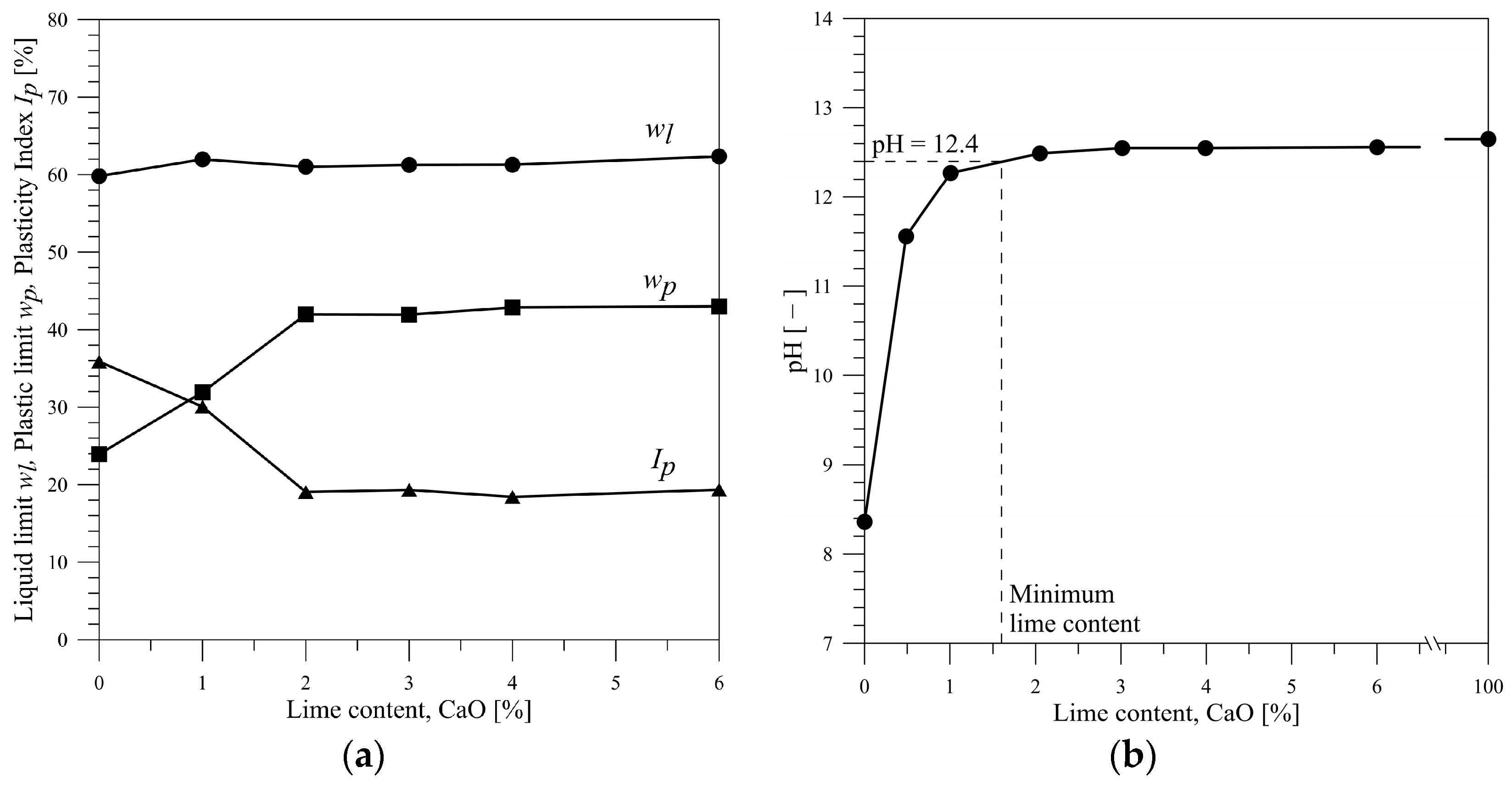
3.1. Modification of the Soil Plasticity and Definition of the Minimum Lime Content

The values of the liquid limit, plastic limit and plasticity index are plotted in Figure 2a as a function of the lime content CaO. The data show that after an initial increase, the plastic limit assumed a constant value equal to about wp = 42% for a lime content higher than 2%. The liquid limit shows a small tendency to increase (wl varied from 60 to 62%), as usually occurs in clays of limited activity [26,41]. As a result, the plasticity index initially decreased, and, beyond 2% lime, it assumed a constant value equal to 19%. This trend is evidence of the variation in the thickness of the diffused double electric layer of clayey particles, resulting from cation exchanges and the aggregation of clayey particles [12,42].
Measurements of the pH values at a constant temperature T = 25 °C were conducted on the aqueous mixture (100 mL of distilled water) including 25 g of clay and an amount of lime corresponding to percentages varying between 0 and 6. Moreover, the value of pH was also determined for a pure solution of quicklime and water. According to Eades and Grimm [43,44], the minimum lime content needed to satisfy the affinity between the soil and the lime can be read when the mixture has a pH value equal to 12.4 (Figure 2b). This content ensures that the short-term reaction induced by the treatment is being completed. Then, it can be assumed that only for a dosage greater than 1.6% is the lime treatment effective for the short-term reaction, and, starting from a 2% lime content, the lime–clay mixtures keep a residual lime amount suitable to developing pozzolanic reactions. These reactions are delayed in time, and they can be expected to progressively improve the mechanical behaviour of the scaly clay.

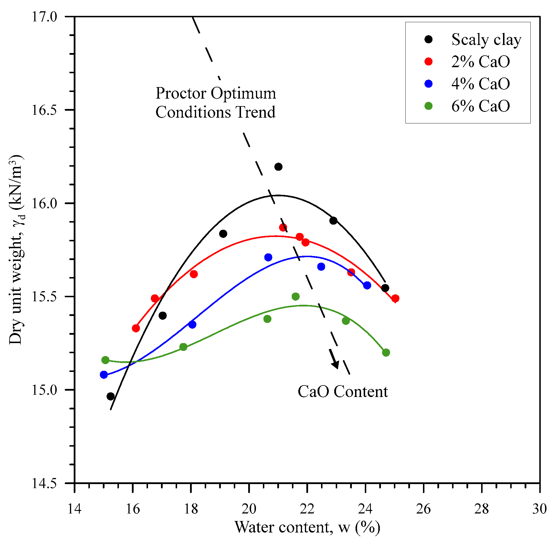
3.2. Modification of the Compaction Characteristics

The compaction curves for the untreated scaly clay and for material treated with 2, 4 and 6% of lime are reported in Figure 3. As clearly shown, the optimum conditions trend moves toward a higher water content and lower dry unit weight with an increase in the lime content. Then, for the same compaction energy, the higher the lime content, the lower the dry unit weight. At the same time, the water content at optimum conditions increases with the lime content. Moreover, by increasing the lime content the lime–clay mixture is less sensitive to compaction, and the bell-shaped curve, typical of compacted clayey materials, tends to disappear.
The results of the preliminary standard Californian Bearing tests CBR carried out according to ASTM D1883-21 standard [45] prove that lime treatment is already effective after 4 days of soaking (a total surcharge load corresponding to 2.4 kPa) and adding 2% lime (CBR = 17%), although the values of the swelling strain, εswell, are still significant (εswell = 1.5%). In fact, untreated compacted scaly clay showed insignificant penetration strength (CBR = 1.7%) and higher swelling upon saturation (εswell = 3%).

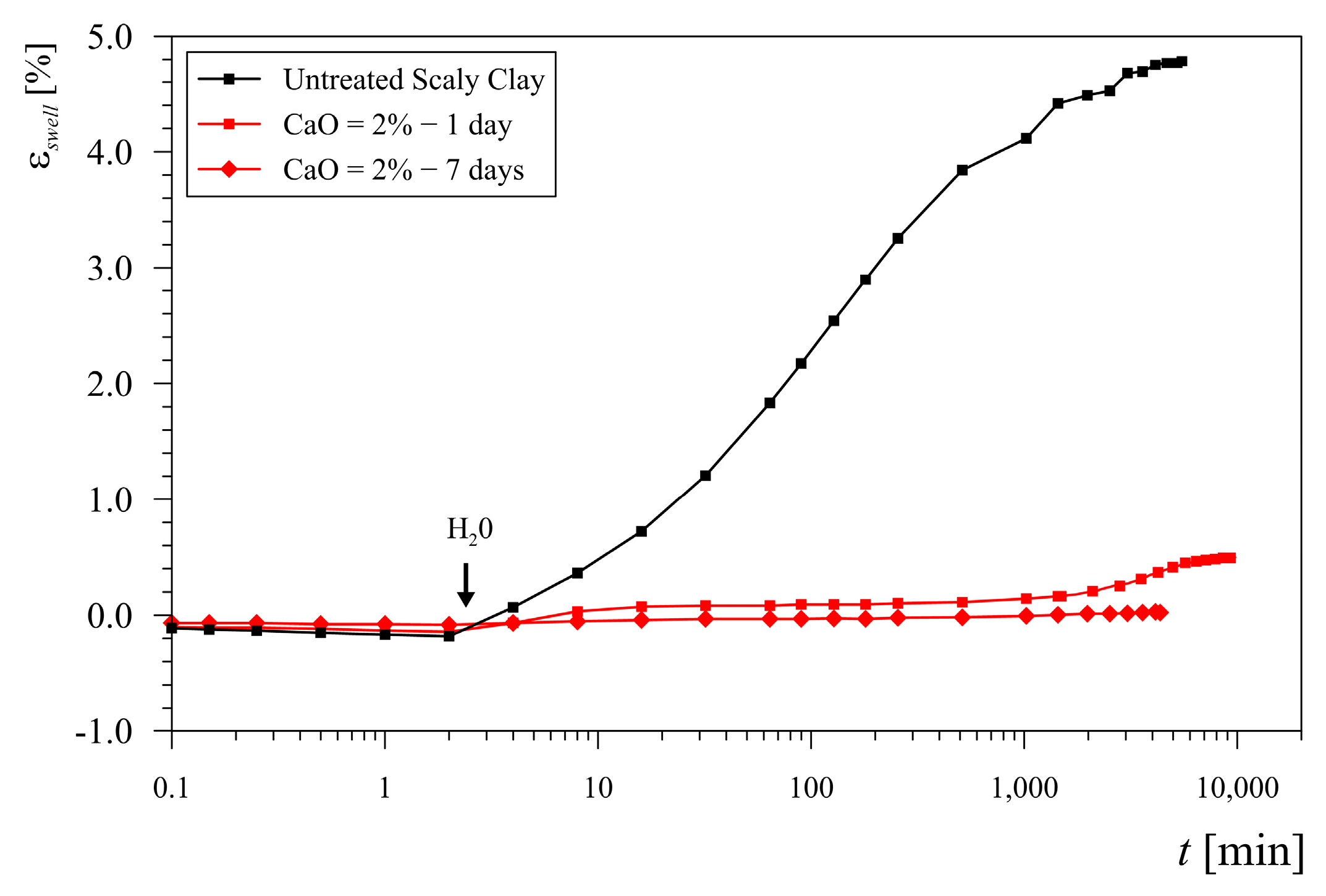
3.3. Swelling Behaviour in 1D Condition

To better investigate the behaviour upon wetting at low stress (σv = 10 kPa), the untreated and treated specimens at 2% lime were tested in the oedometric cell (1D condition). The treated specimens were tested after 1 and 7 days of curing. As clearly shown in Figure 4, the untreated clay experienced quick and very high swelling; after 4 days the swelling strain was equalised at εswell = 4.8%, and the specimens proved to be saturated.
The data shows that lime treatment is effective in inhibiting swelling behaviour. In fact, after 7 days, clay treated with 2% lime was still insensitive to the volume increase induced by saturation, i.e., the saturation process occurred at constant volume (εswell = 0.015%). Since the majority reduction in swelling potential takes place after 1 day of curing, this mechanism can be mainly related to the capacity of lime to satisfy the affinity between clay and water. Although less evident, it can be observed that the secondary swelling, which is typically observed after 2–3 days, is also reduced with curing time because of the formation of pozzolanic products around the clayey aggregates.

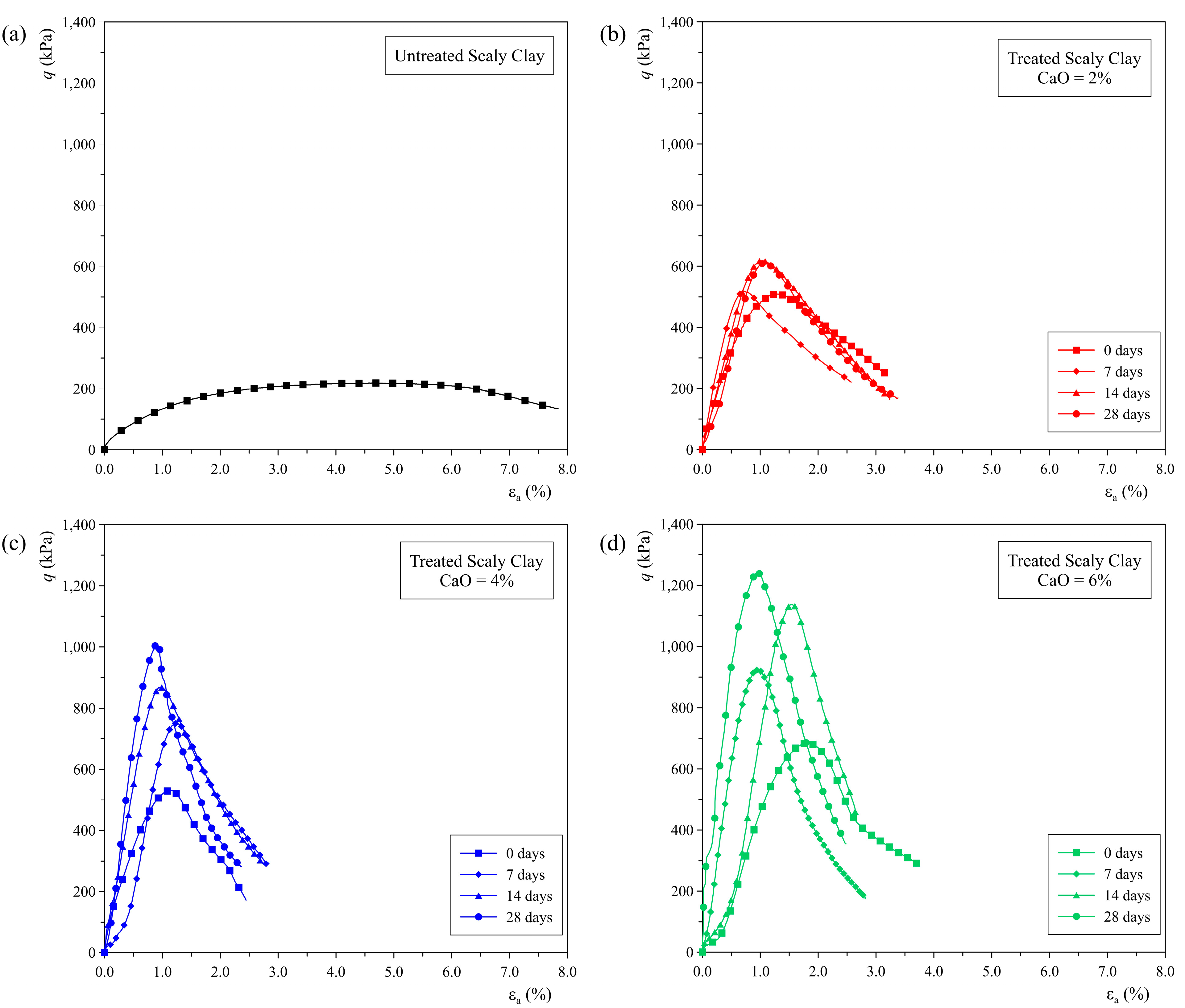
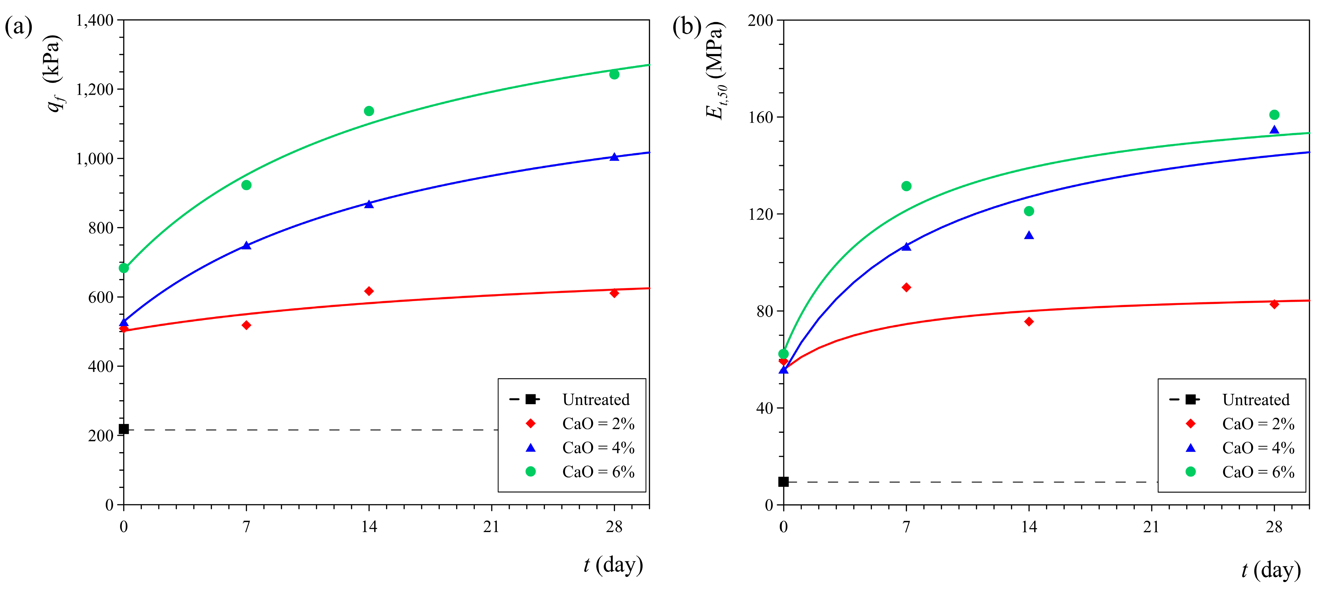
3.4. Unconfined Compression Tests

The results of the unconfined compression tests carried out on the untreated and treated scaly clays are represented in Figure 5 in terms of the deviatoric stress q vs. the axial strain ε a . The data show a clear stress–strain behaviour depending on the amount of lime used for the treatment of scaly clay.
Indeed, starting from the ductile and poor strength behaviour of the compacted scaly clay (untreated specimens), the treatment induces a high increase in strength and stiffness. However, irrespective of the lime content, the treated clays are characterised by a clear peak of strength, which appears for lower axial strain, i.e., in the range between 1 and 2%. The strain-softening behaviour is more and more evident with an increase in lime content and curing time.
The evolution of the unconfined compressive strength is represented in Figure 6a where, for the clay treated with different amounts of lime (untreated clay, CaO = 2, 4 and 6%), the deviatoric stress at failure qf is plotted against the time t. In contrast, in Figure 6b, the undrained elastic modulus Et,50, calculated as the tangent of the curve at the value corresponding to 50% of the deviatoric stress at failure, is represented as a function of time t. As shown in the same figures, the datasets can be well interpreted using hyperbolic type equations, reformulated in terms of the unconfined compression strength UCS (Figure 6a) and stiffness (Figure 6b) as a function of the time. For t = 0, the increase in both strength and stiffness is already evident. The unconfined compressive strength of the treated clay was about two to three times (qf = 509 ÷ 694 kPa) higher than that of the untreated clays (qf = 219 kPa). Even more substantial improvements are evident regarding stiffness. Indeed, the treated clay is stiffer (Et,50 = 56 ÷ 62 MPa) than the untreated clay (Et,50 = 9.5 MPa). Further improvements in the mechanical behaviour of scaly clay, in terms of both strength and stiffness, are provided progressively with time by pozzolanic reactions of lime with clayey particles. The increase in strength and stiffness with time is more significant as the lime content rises, although for 2% lime the improvement over time is rather limited.

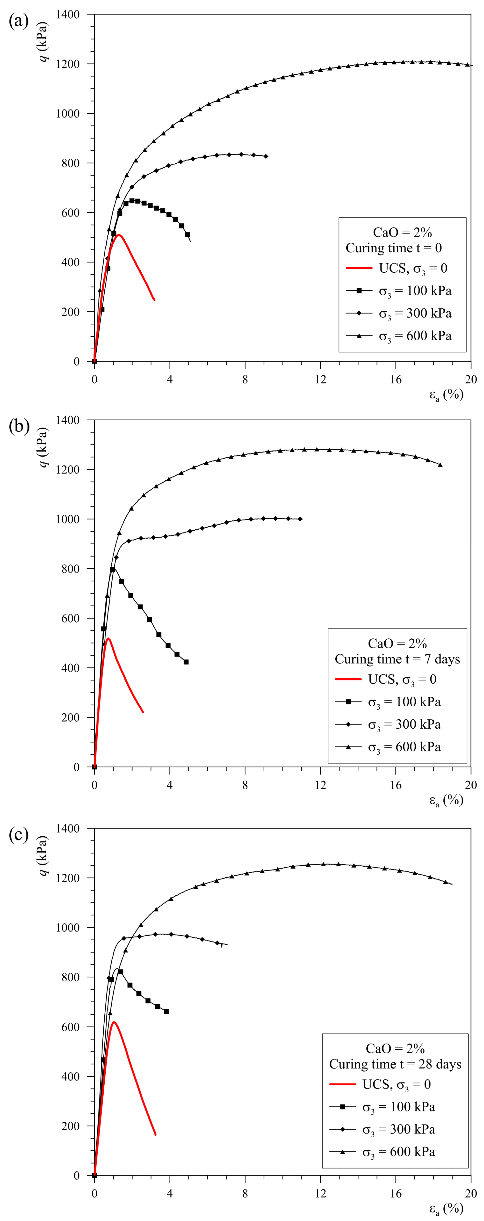
3.5. Triaxial Compression Tests

3.5.1. Unconsolidated–Undrained Triaxial Test

The results of the unconfined compression tests reported in Figure 6 proved that the stress–strain behaviour of the scaly clay treated with 2% lime reached stationary conditions after 14–28 days of curing. Then, this mixture was selected to better investigate the static and dynamic responses under confined conditions. In this way, the construction of superposed layers of embankment was simulated by increasing the total confining stress applied to the specimens.
The results of undrained unconsolidated triaxial compression tests carried out on scaly clay treated with 2% lime after 0, 7 and 28 days are reported in Figure 7a, Figure 7b and Figure 7c, respectively. For each curing time, the tests were carried out by applying a confining pressure σc = σ3 equal to 100, 300 and 600 kPa. For comparison, in the same figures, the data from unconfined tests were reported again (red lines).
The results show that there is a clear effect of increasing the confining pressure on the undrained shear strength behaviour. This is because the specimens maintain their unsaturated state throughout the tests. Due to the compressibility of the pore fluid (air plus water), the pore water pressure, which is negative, slightly increases while the effective stresses vary with increasing confining stress. This increases the shear strength of the material as the effective stresses increase. Moreover, because of the increasing confining pressure, the typical strain-softening behaviour of treated clay changes into a strain-hardening behaviour. With reference to the evolution with time of the strength, it is worth noticing again that the greatest increase in the strength of the clay treated with 2% lime was obtained between 0 and 7 days.

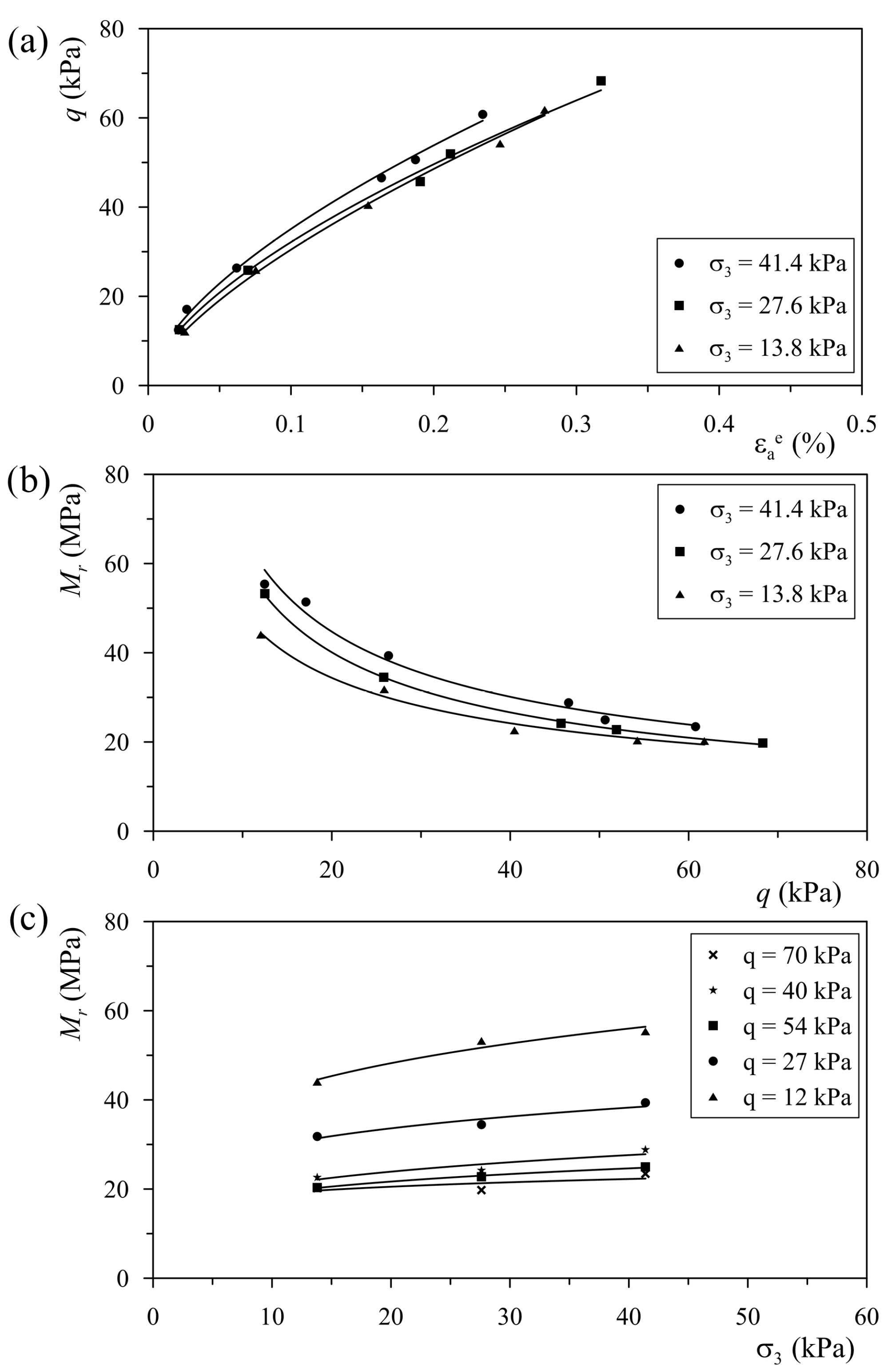
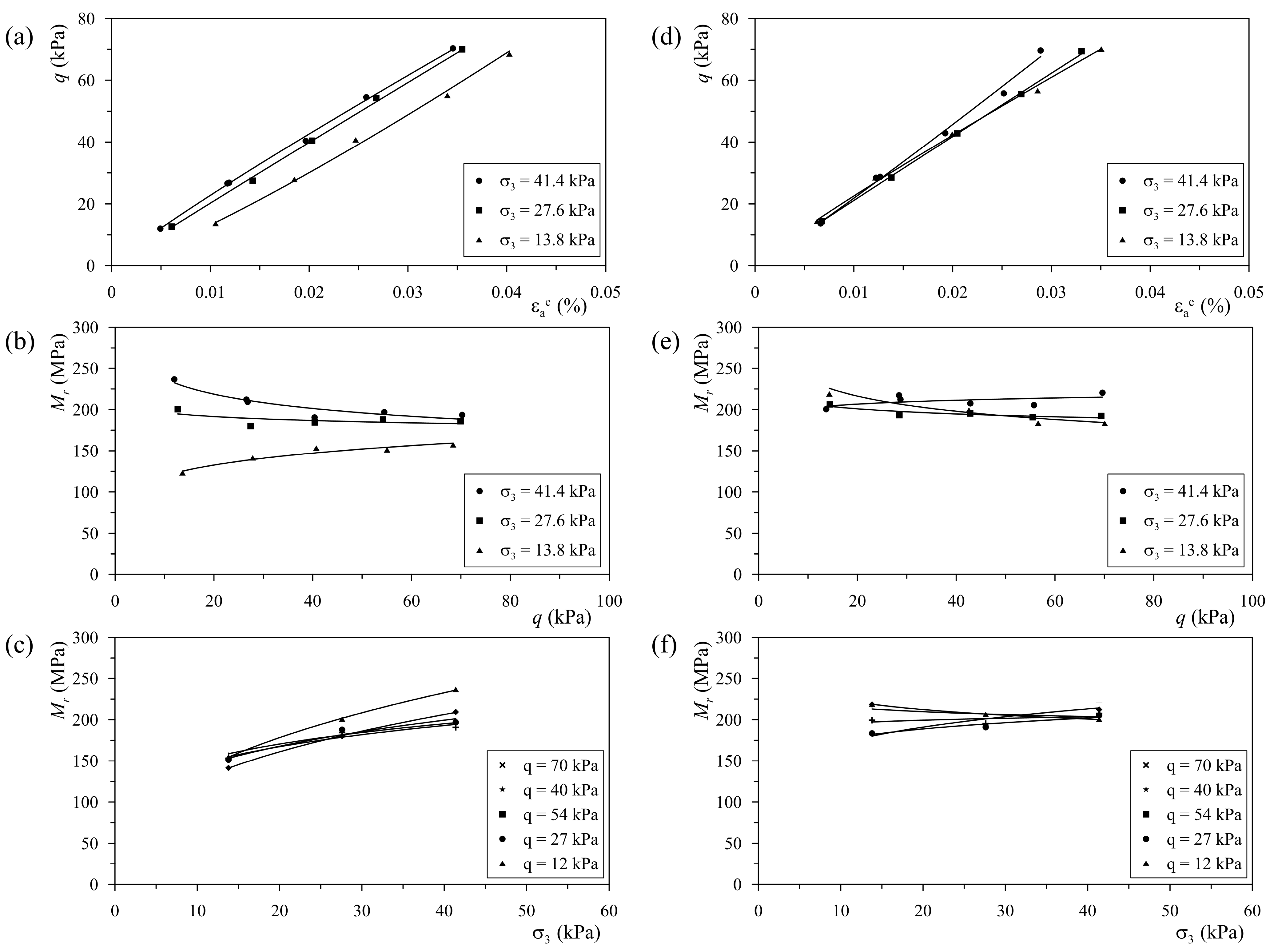
3.5.2. Resilient Modulus Tests

Dynamic testing for resilient modulus determinations was carried out on scaly clay treated with 2% lime after 7 and 28 days of curing. For comparison, untreated scaly clay was also tested with the same procedure. The results of these tests are shown in Figure 8 (for untreated clay) and in Figure 9 (for treated clay) in terms of the maximum deviatoric stress qmax as a function of the elastic strain ε a e (Figure 8a and Figure 9a,d), the resilient modulus Mr as a function of the deviatoric stress qmax (Figure 8b and Figure 9b,e) and the resilient modulus Mr as a function of the confining stress σ3 (Figure 8c and Figure 9c,f).
The response of the untreated clay to dynamic testing (Figure 8) is characterised by a markedly curvilinear relationship between the deviatoric stress and elastic strain, regardless of the confining stress level considered. Consequently, the secant resilient modulus decreases with increasing deviatoric stress and increases with the confining pressure. For the highest values of deviatoric stress, the resilient modulus proves to be Mr = 20 MPa, which is unsatisfactory for sustaining dynamic effects induced by traffic loads.
On the other hand, the deviatoric stress q vs. elastic strain ε a e relationship of the treated specimens takes on a linear trend. Basically, due to the improvement in mechanical properties, the material is further from the yield conditions, and, for this reason, the range of variation in the elastic strain ε a e is reduced by an order of magnitude (Figure 9a,d). Therefore, analysing the results of the test performed on the 2% CaO-treated clay specimen subjected to 7 days of curing, a limited reduction in the resilient modulus is observed as the deviatoric stress increases; however, a greater variation in the modulus is found as the confining pressure changes. Specifically, it is observed that, for low levels of deviatoric stress, the resilient modulus varies from Mr = 250 MPa, for a confining pressure equal to σ3 = 41.4 kPa, to Mr = 125 MPa, for a confining pressure equal to σ3 = 13.8 kPa; for high levels of deviatoric stress, it varies from Mr = 200 MPa to Mr = 150 MPa, for a confining pressure equal to σ3 = 41.4 kPa and σ3 = 13.8 kPa, respectively.
The results of the test performed on the treated clay after 28 days of curing show insignificant changes in the resilient modulus with both confining pressure and deviatoric stress changes. In fact, the trend of the Mr vs. q plots is sub-horizontal, and the resilient modulus fluctuates around the value Mr = 200 MPa. This behaviour largely meets the mechanical requirements for use as pavement subgrade layers [46,47].
The monotonic failure phase of the dynamic triaxial compression tests (Figure 10), performed with a confining pressure σ3 = 34.5 kPa, shows that the untreated clay exhibits a ductile and poor behaviour, while the treated clay still exhibits stiff behaviour characterised by a peak of strength. The higher the peak of strength, the longer the curing time. Specifically, the untreated clay specimen exhibits a maximum deviatoric stress equal to qmax = 162 kPa, while the strength of the treated clay rises to qf = 461 kPa and qf = 640 kPa for 7 to 28 days of curing, respectively.

4. Discussion

The comprehensive experimental programme conducted on the scaly clay used proved that lime treatment induces a significant improvement for this type of material, from both the physical and mechanical points of view, and reduces the sensitivity to water. These results are consistent with those obtained by lime treatment of other clays of different origin, mineralogy, and microstructure (e.g., [12,14,16,23,27]). However, it is well known that these intrinsic properties of the geomaterials still affect their performance when they are stabilised with chemical additives (e.g., [41]). Then, this treated geomaterial could be successfully used for the construction of earthworks, such as road or railway embankments.
In the case of a road embankment, the highest stress level can be reached at the base of the embankment, while, near the slope, the confining pressure is reduced to zero. Moreover, the magnitude and the direction of the main stresses depend both on the depth and the position of the considered point within the embankment. Considering that embankments generally are efficaciously protected from environmental conditions, it can be assumed that the negative pore water pressure—due to the unsaturated conditions—is kept, and the as-compacted conditions are not significantly altered. Hence, the variation in the stress state of the geomaterial depends exclusively on the number of layers above it, i.e., the height of the embankment, and the traffic loads.
Considering that, in general, the rate of load applications is high if compared to the drainage capacity of a soil embankment, the loading process acts in undrained conditions. Consequently, in this research, the behaviour of the geomaterial in the embankment was efficaciously explored at a laboratory scale, by means of undrained unconfined and confined tests. Indeed, in the filling of embankment layers, the stress state acts in static conditions because of the distance from the road pavement. By contrast, traffic loads are the main stress acting in the subgrade soil layers, and, for this reason, it was fundamental to investigate the behaviour of the geomaterial during repeated cyclic loads. Under the latter conditions, the resilient modulus test is representative of the evolution of the stress state under dynamic load combinations and provides the most important factor in evaluating the performance of geomaterials and their capacity to support loads.
With this regard, the data collected in this research with resilient modulus tests and triaxial compression tests highlight that, only after treatment with 2% lime, scaly clay acquires stability features regarding dynamic and repeated loading. To prove this, the Mohr circles, in terms of total stresses, were plotted in Figure 11 in order to compare the undrained strength measured at the end of the resilient modulus tests, i.e., after the loading cycles, with the ones obtained with monotonic loading in the undrained triaxial cell and with UCS tests after 7 and 28 days of curing time. It should be noted that, as expected, the shear strength increases with increasing confining pressure due to the unsaturated state of the specimens. As shown, in the case of 7 days of curing, the Mohr circle related to the resilient modulus tests is significantly lower than the shear strength envelope in terms of the total stress based on UCS and triaxial tests. By contrast, in the case of 24 days of curing, the shear strength determined after the cycling dynamic loads coincided with the shear strength of the monotonic tests. Hence, there is a clear detrimental effect of repeated cyclic loads on the mechanical response of scaly clay when the pozzolanic processes are not yet completed, as in the case of 7 days of curing.
Although the obtained results highlight the mechanical improvements provided by the addition of lime, it might be interesting in the future to investigate the mechanical behaviour of treated scaly clay, considering the evolution of the pore water pressure in the undrained loading stage and the response of the material in the long-term time scale, i.e., in drained conditions. However, it is worth noting that the former can be negligible, due to the unsaturated state, and the latter may be considered less disadvantageous from the design point of view because of the time-dependent improvement of the mechanical response related to the development of the pozzolanic reactions and the dissipation of pore overpressures generated during construction of the embankment, if any.

5. Conclusions

The paper explored the possibility of widening the application of scaly clays, which are widespread all over the world, by improving their mechanical properties via treatment with lime. This study was needed because, so far, the literature lacks evidence of the effectiveness of the lime treatments on structurally complex clayey formations soils. To this aim, different lime contents were investigated, and a curing time of up to 28 days was considered.
The obtained results prove that the lime treatment induces significant modifications in the compaction properties and the swelling behaviour of the geomaterial. Significant improvements were also observed regarding the strength and stiffness. Irrespective of the lime content, the treated clays were characterised by strain-softening behaviour. However, the brittleness of the material can be reduced by increasing the lateral confinement. Indeed, the undrained triaxial compression tests showed that for confining pressures above 300 kPa, the mechanical behaviour became strain-hardening in type. Dynamic tests to determine the resilient modulus have shown that the mixtures tested meet the requirements for subgrade layers for road pavements and are insensitive to the damaging effects of the repeated loading produced by vehicle traffic. The mechanical improvements obtained with time are due to the pozzolanic reactions between the lime and the clayey particles: only the mixture with a low lime content (2%) reaches a steady strength after 14–28 days of curing; for a higher lime content, longer curing times are required to complete the stabilisation process. These results are consistent with the amount of lime required to satisfy the affinity between lime and clay, i.e., to complete the short-term reactions induced by the treatment, which in preliminary tests was found to be 1.6%.
In conclusion, the scaly clays considered in this study can be effectively treated with lime to produce a geomaterial suitable for the construction of road and railway embankments or pavement subgrade. Scaly clay formations, in spite of their different origins, share a number of characteristics in terms of microstructure and mechanical behaviour. Therefore, on the basis of the results obtained, it can be expected that the treatments will be effective in other scaly clays from other parts of the world, but the improvements in the mechanical behaviour will have to be quantified in detail by testing the different lime–scaly clay mixtures. In conclusion, the results of this study are significant for extending the use of this widespread geomaterial to new applications, thus avoiding landfills and increasing the sustainability of civil engineering works involving excavations in scaly clays. Indeed, further studies are needed to investigate the durability and long-term performance on a large scale by monitoring a trial embankment.

Author Contributions

Conceptualisation, M.R. and C.C.; methodology, M.R. and C.C; investigation, M.R. and C.C.; writing—original draft preparation, M.R. and C.C.; writing—review and editing, M.R. and C.C. All authors have read and agreed to the published version of the manuscript.

Funding

This research received no external funding.

Data Availability Statement

The data presented in this study are available upon request from the corresponding author.

Conflicts of Interest

The authors declare no conflict of interest.

References

  1. AGI, Associazione Geotecnica Italiana. Geotechnical properties and slope stability in structurally complex clay soils. Geotech. Eng. Italy 1985, 2, 189–225. [Google Scholar]
  2. Fearon, R.; Coop, M.R. The influence of landsliding on the behaviour of a structurally complex clay. Q. J. Eng. Geol. Hydrogeol. 2002, 35, 25–32. [Google Scholar] [CrossRef]
  3. Hight, D.W.; Gasparre, A.; Nishimura, S.; Minh, N.A.; Jardine, R.J.; Coop, M.R. Characteristics of the London Clay from the terminal 5 site at Heathrow airport. Géotechnique 2007, 57, 3–18. [Google Scholar] [CrossRef]
  4. Laurich, B.; Urai, J.L.; Nussbaum, C. Microstructures and deformation mechanisms in Opalinus Clay: Insights from scaly clay from the Main Fault in the Mont Terri Rock Laboratory (CH). Solid Earth 2017, 8, 27–44. [Google Scholar] [CrossRef]
  5. D’Onofrio, A.; Picarelli, L.; Santo, A.; Urciuoli, G. The Red Flysch Formation in Southern Apennines: Lithological and Structural Features and Challenges in Geotechnical Characterization and Modelling. Rock Mech. Rock Eng. 2023, 56, 8375–8393. [Google Scholar] [CrossRef]
  6. Airò Farulla, C.; Cafiso, F.; Calvi, F.; Rosone, M. Safeguarding historic towns on hilltops threatened by land sliding: The case of San Fratello in Sicily. Ital. Geotech. J. 2015, 49, 7–28. [Google Scholar]
  7. Cotecchia, F.; Vitone, C.; Santaloia, F.; Pedone, G.; Bottiglieri, O. Slope instability processes in intensely fissured clays: Case histories in the Southern Apennines. Landslides 2015, 12, 877–893. [Google Scholar] [CrossRef]
  8. Nardelli, V.; Coop, M.R.; Vitone, C.; Chen, S. The inter-scale behaviour of two natural scaly clays. Géotechnique Lett. 2016, 6, 205–210. [Google Scholar] [CrossRef]
  9. Rosone, M.; Airò Farulla, C.; Ferrari, A. Shear strength of a compacted scaly clay in variable saturation conditions. Acta Geotech. 2016, 11, 37–50. [Google Scholar] [CrossRef]
  10. Rosone, M.; Ferrari, A. Role of Stress History on the Swelling-Shrinkage Behavior of Compacted Scaly Clay. Int. J. Geomech. 2022, 22, 04022135. [Google Scholar] [CrossRef]
  11. Correia, A.G.; Winter, M.G.; Puppala, A.J. A review of sustainable approaches in transport infrastructure geotechnics. Transp. Geotech. 2016, 7, 21–28. [Google Scholar] [CrossRef]
  12. Locat, J.; Berube, M.A.; Choquette, M. Laboratory investigations on the lime stabilization of sensitive clays: Shear strength development. Can Geotech. J. 1990, 27, 294–304. [Google Scholar] [CrossRef]
  13. Boardman, D.I.; Glendinning, S.; Rogers, C.D.F. Development of stabilisation and solidification in lime-clay mixes. Geotechnique 2001, 51, 533–543. [Google Scholar] [CrossRef]
  14. Consoli, N.C.; Prietto, P.D.M.; Lopes, L.S.; Winter, D. Control factors for the long-term compressive strength of lime treated sandy clay soil. Transp. Geotech. 2014, 1, 129–136. [Google Scholar] [CrossRef]
  15. Poncelet, N.; François, B. Effect of laboratory compaction mode, density and suction on the tensile strength of a lime-treated silty soil. Transp. Geotech. 2022, 34, 100763. [Google Scholar] [CrossRef]
  16. Abdi, M.R.; Wild, S. Sulphate expansion of lime-stabilized kaolinite: I. Physical characteristics. Clay Miner. 1993, 28, 555–567. [Google Scholar] [CrossRef]
  17. Zhao, H.; Liu, J.; Guo, J.; Zhao, C.; Gong, B. Reexamination of lime stabilization mechanisms of expansive clay. J. Mater. Civ. Eng. 2015, 27, 04014108. [Google Scholar] [CrossRef]
  18. Metelková, Z.; Boháč, J.; Přikryl, R.; Sedlářová, I. Maturation of loess treated with variable lime admixture: Pore space textural evolution and related phase changes. Appl. Clay Sci. 2012, 61, 37–43. [Google Scholar] [CrossRef]
  19. Pomakhina, E.; Deneele, D.; Gaillot, A.C.; Paris, M.; Ouvrard, G. Si solid state NMR investigation of pozzolanic reaction occurring in lime-treated Ca-bentonite. Cem. Concr. Res. 2012, 42, 626–632. [Google Scholar] [CrossRef]
  20. Al-Mukhtar, M.; Khattab, S.; Alcover, J.F. Microstructure and geotechnical properties of lime-treated expansive clayey soil. Eng. Geol. 2012, 139–140, 17–27. [Google Scholar] [CrossRef]
  21. Chakraborty, S.; Nair, S. Impact of different hydrated cementitious phases on moisture-induced damage in lime-stabilized subgrade soils. Road Mater. Pavement Des. 2018, 19, 1389–1405. [Google Scholar] [CrossRef]
  22. Vitale, E.; Deneele, D.; Russo, G. Effects of carbonation on chemo-mechanical behaviour of lime-treated soils. Bull. Eng. Geol. Environ. 2021, 80, 2687–2700. [Google Scholar] [CrossRef]
  23. Kleib, J.; Lesueur, D.; Maherzi, W.; Benzerzour, M. Carbonation of a lime treated soil subjected to different curing conditions. Transp. Geotech. 2024, 44, 101174. [Google Scholar] [CrossRef]
  24. Bell, F.G. Lime stabilization of clay minerals and soils. Eng. Geol. 1996, 42, 223–237. [Google Scholar] [CrossRef]
  25. Puppala, A.J.; Mohammad, L.; Allen, A. Engineering behavior of lime-treated Louisiana subgrade soil. Transp. Res. Rec. 1996, 1546, 24–31. [Google Scholar] [CrossRef]
  26. Rosone, M.; Celauro, C.; Ferrari, A. Microstructure and shear strength evolution of a lime-treated clay for use in road construction. Int. J. Pavement Eng. 2020, 21, 1147–1158. [Google Scholar] [CrossRef]
  27. Khemissa, M.; Mahamedi, A.; Mekki, L. Laboratory investigation of the treatment effects by hydraulic binders on the physical and mechanical properties of an overconsolidated expansive clay. Int. J. Geotech. Eng. 2017, 13, 594–607. [Google Scholar] [CrossRef]
  28. Maubec, N.; Deneele, D.; Ouvrardb, G. Influence of the clay type on the strength evolution of lime treated material. Appl. Clay Sci. 2017, 135, 107–114. [Google Scholar] [CrossRef]
  29. Belal, T.; Ghembaza, M.S.; Bellia, Z. An investigation of the effects of cementation and temperature on the water retention curve of compacted silt. Int. J. Geotech. Eng. 2019, 16, 33–43. [Google Scholar] [CrossRef]
  30. Rosone, M.; Megna, B.; Celauro, C. Analysis of the chemical and microstructural modifications effects on the hydro-mechanical behaviour of a lime-treated clay. Int. J. Geotech. Eng. 2021, 15, 447–460. [Google Scholar] [CrossRef]
  31. Padmaraj, D.; Arnepalli, D.N. Mechanism of Carbonation in Lime-Stabilized Silty Clay from Chemical and Microstructure Perspectives. Int. J. Geosynth. Ground Eng. 2021, 7, 74. [Google Scholar] [CrossRef]
  32. Rosone, M.; Airò Farulla, C.; Ferrari, A.; Torta, C.; Celauro, C. Suction controlled drying and wetting cycle effects on the volumetric behaviour of a lime-treated high plasticity clay. E3S Web Conf. 2016, 9, 14020. [Google Scholar] [CrossRef]
  33. Di Sante, M.; Bernardo, D.; Bellezza, I.; Fratalocchi, E.; Mazzieri, F. Linking small-strain stiffness to development of chemical reactions in lime-treated soils. Transp. Geotech. 2022, 34, 100742. [Google Scholar] [CrossRef]
  34. Rosone, M.; Moscato, F.; Celauro, C.; Ziccarelli, M. Evaluation of the In-Situ Behaviour of a Lime-Treated Clay in a Real-Scale Experimental Embankment. In Geotechnical Engineering in the Digital and Technological Innovation Era. CNRIG 2023; Ferrari, A., Rosone, M., Ziccarelli, M., Gottardi, G., Eds.; Springer Series in Geomechanics and Geoengineering; Springer: Cham, Switzerland, 2023. [Google Scholar]
  35. EN 14227-11: 2006; Hydraulically Bound Mixtures Specifications, Part 11: Soil Treated by Lime. Comité Européen de Normalisation (CEN): Brussels, Belgium, 2006.
  36. Airò Farulla, C.; Celauro, B.; Celauro, C.; Rosone, M. Field test of lime treatment of clayey soils for railways and road works. Railway Eng. 2014, 69, 729–752. [Google Scholar]
  37. EN 459-1: 2015; Building Lime-Part 1: Definitions, Specifications, and Conformity Criteria. Comité Européen de Normalisation (CEN): Brussels, Belgium, 2015.
  38. C977:2003; Standard Specification for Quicklime and Hydrated Lime for Soil Stabilization. American Society for Testing Materials (ASTM): West Conshohocken, PA, USA, 2003.
  39. C911:2006; Standard Specification for Quicklime, Hydrated Lime, and Limestone for Chemical Uses and Industrial Uses. American Society for Testing Materials (ASTM): West Conshohocken, PA, USA, 2006.
  40. Bhuvaneshwari, S.; Robinson, R.; Gandhi, S. Behaviour of Lime Treated Cured Expansive Soil Composites. Indian Geotech. J. 2014, 44, 278–293. [Google Scholar] [CrossRef]
  41. AASHTO T307-99; Standard Method of Test for Determining the Resilient Modulus of Soils and Aggregate Materials. American Association of State Highway and Transportation Officials: Washington, DC, USA, 2003.
  42. Barman, D.; Dash, S.K. Stabilization of expansive soils using chemical additives: A review. J. Rock Mech. Geotech. Eng. 2022, 14, 1319–1342. [Google Scholar] [CrossRef]
  43. Eades, J.; Grim, R. A quick test to determine lime requirements of lime stabilization. Highway Res. Rec. 1996, 139, 61–72. [Google Scholar]
  44. D6276:19999; Standard Test Method for Using pH to Estimate the Soil-Lime Proportion Requirement for Soil Stabilization. American Society for Testing Materials (ASTM): West Conshohocken, PA, USA, 2021.
  45. D1883: 2021; Standard Test Method for California Bearing Ratio (CBR) of Laboratory-Compacted Soils. American Society for Testing Materials (ASTM): West Conshohocken, PA, USA, 2021.
  46. American Association of State Highway and Transportation Officials (AASTHO). M-E PDG, Mechanistic-Empirical Pavement Design Guide: A Manual of Practice, 3rd ed.; AASTHO: Washington, DC, USA, 2020. [Google Scholar]
  47. Consiglio Nazionale delle Ricerche (CNR). Catalogo Delle Pavimentazioni Stradali; B.U. n. 178; CNR: Roma, Italy, 1995. (In Italian)
Figure 1. Axial loading at constant confining pressure during cyclic triaxial compression tests for resilient modulus determination.
Geosciences 14 00017 g001
Figure 2. Liquid limit, plastic limit and plasticity index as a function of the lime content (a) and pH determinations of the different aqueous mixtures of powered scaly clay and quicklime at T = 25 °C (b).
Geosciences 14 00017 g002
Figure 3. Compaction curve (Proctor Standard Energy) for treated and untreated scaly clay at 2, 4 and 6% of lime.
Geosciences 14 00017 g003
Figure 4. Results of the swelling tests carried out at vertical total stress σv = 10 kPa on treated and untreated scaly clay at 2% lime after 1 and 7 days of curing.
Geosciences 14 00017 g004
Figure 5. Results of the unconfined compression tests carried out on untreated scaly clay (a) and treated scaly clay at 2% (b), 4% (c) and 6% (d) lime content after 0, 7, 14 and 28 days of curing.
Geosciences 14 00017 g005
Figure 6. Evolution with time of the deviatoric stress at failure qf (a) and the tangent modulus at 50% of deviatoric stress at failure Et,50 (b) from unconfined compression tests carried out on untreated and treated scaly clay.
Geosciences 14 00017 g006
Figure 7. Results of unconsolidated undrained triaxial compression tests carried out on scaly clay treated with 2% lime after 0 (a), 7 (b) and 28 (c) days of curing time.
Geosciences 14 00017 g007
Figure 8. Results of dynamic triaxial compression tests carried out on the untreated scaly clay in terms of maximum deviatoric stress qmax as a function of elastic strain εae (a), resilient modulus Mr as a function of deviatoric stress qmax (b) and resilient modulus Mr as a function of the confining stress σ3 (c).
Geosciences 14 00017 g008
Figure 9. Results of dynamic triaxial compression tests carried out on the treated scaly clay after 7 (ac) and 28 days (df) of curing in terms of maximum deviatoric stress qmax as a function of elastic strain εae (a,d), resilient modulus Mr as a function of deviatoric stress qmax (b,e) and resilient modulus Mr as a function of confining stress σ3 (c,f).
Geosciences 14 00017 g009
Figure 10. Results of failure stage of dynamic triaxial compression tests carried out on untreated and treated scaly clay after 7 and 28 days in terms of deviatoric stress q as a function of axial strain εa.
Geosciences 14 00017 g010
Figure 11. Mohr circles in terms of total stresses at failure in the UCS tests (σ3 = 0), in undrained triaxial tests carried out at σ3 equal to 100, 300 and 600 kPa and in the final monotonic stage of resilient modulus tests RM carried out at constant confining pressure equal to σ3 = 34.5 kPa on treated scaly clay after (a) 7 and (b) 28 days.
Geosciences 14 00017 g011
Table 1. Details of the experimental plan carried out.
Natural Soil–Scaly Clay
  • Specific gravity
  • Natural water content
  • Void ratio
  • Degree of saturation
  • Particle size distribution
  • Atterberg limits
  • X-ray diffraction
  • Calcium carbonate content
Lime (CaO)
  • Calcium oxide content
  • Magnesium oxide content
  • Gradation
  • Water reactivity
Lime–Soil Mixtures
  • Atterberg limits @ 0, 1, 2, 3, 4 and 6% CaO
  • pH measurements @ 0, 0.5, 1, 2, 3, 4, 6 and 100% CaO
  • Dynamic compaction @ 0, 2, 4 and 6% CaO
  • Saturation tests in compaction mould @ 0, 2, 4 and 6% CaO
  • Bearing capacity (CBR) tests @ 0, 2, 4 and 6% CaO
  • Swelling test in oedometric condition @ 0 and 2% CaO and for 1 and 7 days of curing
  • Unconfined compressive strength @ 0, 2, 4 and 6% CaO and for 0, 7, 14 and 28 days of curing
  • Unconsolidated undrained triaxial test @ 2% CaO and for 0, 7 and 28 days
  • Resilient modulus (RM) tests @ 0 and 2% CaO and for 0, 7 and 28 days of curing
  • Monotonic failure after RM tests @ 0 and 2% CaO and for 0, 7 and 28 days of curing
Table 2. Properties of the tested scaly clay in natural conditions (natural water content wn, undisturbed void ratio e0, degree of saturation Sr,0, hygroscopic water content wh, shrinkage limit ws, plastic limit wp, liquid limit wl, specific gravity Gs, clay fraction fc, silt fraction fs and calcium carbonate content CaCO3).
wn
(%)
e0
(−)
Sr,0
(−)
wh
(%)
ws
(%)
wp
(%)
wl
(%)
Gs
(−)
fc
(%)
fs
(%)
CaCO3
(%)
200.650.854.51124602.76554112
Table 3. Main characteristics of the quicklime used (calcium oxide content CaO, magnesium oxide content MgO, water reactivity t60, passing to sieve 2 mm p2, sieve 0.2 mm p0.2, sieve 0.09 mm p0.09 and sieve 0.075 mm p0.075).
CaO
(%)
MgO
(%)
t60
(min)
p2
(%)
p0.2
(%)
p0.09
(%)
p0.075
(%)
94.51.341009986.281.3
Disclaimer/Publisher’s Note: The statements, opinions and data contained in all publications are solely those of the individual author(s) and contributor(s) and not of MDPI and/or the editor(s). MDPI and/or the editor(s) disclaim responsibility for any injury to people or property resulting from any ideas, methods, instructions or products referred to in the content.

