Review

Evaluation of Strength Anisotropy in Foliated Metamorphic Rocks: A Review Focused on Microscopic Mechanisms

by
Umer Waqas
1,
Mohsin Usman Qureshi
2,
Shahab Saqib
3,
Hafiz Muhammad Awais Rashid
1,* and
Ali Murtaza Rasool
4
1
Department of Geological Engineering, University of Engineering & Technology Lahore, Lahore 54890, Pakistan
2
Faculty of Engineering, Sohar University, P.O. Box 44, Sohar 311, Oman
3
Department of Mining Engineering, University of Engineering & Technology Lahore, Lahore 54890, Pakistan
4
Diamer Basha Dam Consultant Group (DBCG), National Engineering Services Pakistan (NESPAK), Lahore 54000, Pakistan
*
Author to whom correspondence should be addressed.
Geosciences 2024, 14(10), 253; https://doi.org/10.3390/geosciences14100253
Submission received: 24 June 2024 / Revised: 9 September 2024 / Accepted: 23 September 2024 / Published: 26 September 2024
(This article belongs to the Section Geomechanics)

Abstract

:
This review paper addresses the recent and past advancements in investigating the anisotropic behavior of foliated metamorphic rock strength subjected to uniaxial or triaxial compression loading, direct or indirect tensile loading, and shear loading. The experimental findings published in the literature show that the strength of foliated rocks is significantly affected by varying the angle β between weak planes and major principal stress. A higher value of strength is reported at β = 0° or 90°; whereas a low strength value is noted at intermediate angles between β = 0° and 90°. The strength anisotropy depends on the degree of schistosity or gneissosity, which is the result of the preferred arrangement of phyllosilicate minerals under differential pressures. The failure of foliated rocks starts at the microscopic scale because of the dislocation slip, plastic kinking, and fracturing in phyllosilicate minerals such as mica. Tensile wing cracks at the tip of the mica propagate parallel to the deviatoric stress. Then, intergranular and intragranular shear-tensile cracks coalesce and lead to rock failure. The weak planes’ orientation controls the mode of failure such that tensile splitting, slip failure, and shear failure across foliations are observed at β = 0°–30°, β = 30°–60°, β = 60°–90° respectively. In the past, several attempts have been made to formulate failure criteria to estimate rock strength using different mathematical and empirical approaches. Over the years, the trend has shifted towards discontinuum modeling to simulate rock failure processes and to solve problems from laboratory to upscaled levels.

1. Introduction

It is important to evaluate the physical and mechanical properties, quality, strength-deformation traits, and failure mechanisms of intact rock masses for safe and cost-effective engineering applications [1]. Rock anisotropy is a significant factor that affects the stability of underground openings, tunneling and excavation operations, and several other civil, geological, and geotechnical engineering applications [2,3,4,5,6,7]. The anisotropy effect makes it difficult to accurately determine a rock mass’s physical and mechanical properties. Overlooking rock anisotropy can lead to failure or severe damage to structures. Generally, anisotropy is caused by the fracture or discontinuity patterns in crystalline rocks, bedding planes in sedimentary rocks, and foliations or weak planes due to phyllosilicate minerals in metamorphic rocks. These anisotropic characteristics may result from other factors such as primary and secondary features, mineral composition, rock fabric, texture, grain size, microstructure, chemical potential gradient, and internal defects [8,9,10,11,12,13].
Foliated metamorphic rocks exhibit the highest degree of anisotropy because of the preferred orientation of their platy minerals [14]. These rocks, including slate, phyllite, schist, and gneiss, are characterized by flaky structures. The weak planes in metamorphic rocks are related to fabric anisotropy which develops because of deformation caused by shear stress and differential stress with mineral recrystallization accommodating the resulting deformation. The engineering significance of foliated metamorphic rocks does not favor the use of strength parameters in design work without considering the anisotropic effect [15]. Researchers have found that the loading direction related to the weak planes governs the strength behavior of foliated metamorphic rocks [16]. The investigation of strength anisotropy in underground or surface engineering applications plays a vital role in controlling several engineering problems such as spalling in underground openings, squeezing, pillar failure, slope instability, etc. [17,18,19,20,21,22].
The isotropic mechanical behavior of rocks has been widely investigated by researchers in the past. However, the anisotropic behavior of foliated metamorphic rocks still needs to be addressed in a broader spectrum to solve rock mechanics problems. In the recent past, the rock mechanics community paid special attention to obtaining comprehensive knowledge for a better understanding of the anisotropic strength behavior of foliated rocks. This review paper aims to comprehensively summarize past and recent advances in laboratory testing and computer-assisted modeling to evaluate the anisotropic mechanical behavior of foliated metamorphic rocks. This study covers the following important aspects: (1) the influence of foliation plane orientations on rock strength subjected to uniaxial or triaxial compression and tension, (2) microstructural characteristics including crack initiation, propagation, and coalescence, (3) damage mechanism and modes of failure, (4) failure criteria, and (5) the role of discrete element modeling in simulating laboratory testing on foliated rocks.

2. Strength Anisotropy

It is evident from the literature that the physical-mechanical behavior of rocks depends on their microscopic properties [23,24,25]. In the case of foliated rocks, the anisotropic effect is an intrinsic characteristic attributed to mineral composition and structural features. Petrographic analysis shows that foliated metamorphic rocks are rich in platy minerals such as biotite, muscovite, chlorite, etc. with their preferred orientations. The phyllosilicate or platy minerals are directionally arranged with the fractures in the quartz-feldspar minerals to form weak planes [22]. The orientation of weak planes plays an important role in governing the strength anisotropy of foliated rocks that can be evaluated under destructive (compression, tension, and shear loading) or nondestructive (P-waves, S-waves, resonance measurements, etc.) laboratory testing. The anisotropic effect of foliated rocks under nondestructive testing is out of the scope of this review.
Past studies showed that the angle β between the major principal stress and weak planes causes strength variations in foliated rocks [26,27,28,29,30,31,32]. The maximum strength was reported at β = 0° or 90°, whereas minimum strength was noted at intermediate angles between β = 0° and 90°. Fereidooni [33] found that β = 30° to 60° is the critical range for the weak plane orientation at which foliated rocks exhibit minimum strength. Based on the experimental results, Singh [18] and Nasseri [20] described the types of anisotropy regarding UCS (uniaxial compressive strength) versus β curves. The variation curve can be U-shaped, Shoulder-shaped, or Undulatory-shaped as shown in Figure 1. The degree of anisotropy in foliated rocks may vary from low to very high. To quantify the grade of the anisotropy, the ratio of compressive strength related to orientation is determined. It is defined as the ratio of maximum compressive strength at β = 90° to minimum compressive strength measured at intermediate angles between β = 0° and 90°. Mathematically it can be expressed as follows:
σ R = σ β = 90 ° σ β = n
where: σ R is the compressive strength ratio and n is an angle value between 0° and 90°.
Ramamurthy [8] proposed an equation to predict the compressive strength of foliated rocks at any orientation between 0° and 90°°. This work was inspired by Jaeger’s equation formulated for the isolated foliation plane [34]:
σ = A B [ C o s 2 β m i n β ]
where σ is the predicted compressive strength, A and B are constants, β m i n is the angle at which strength is minimum, and β is the angle for which strength is being predicted.
Saroglou and Tsiambaos [35] and Ramamurthy [8] measured the anisotropic ratio for some foliated rock to define their grade of anisotropy from weakly/fairly anisotropic (ratio < 1.1) to very highly anisotropic (ratio > 6). Table 1 shows the classification of the anisotropic rocks.
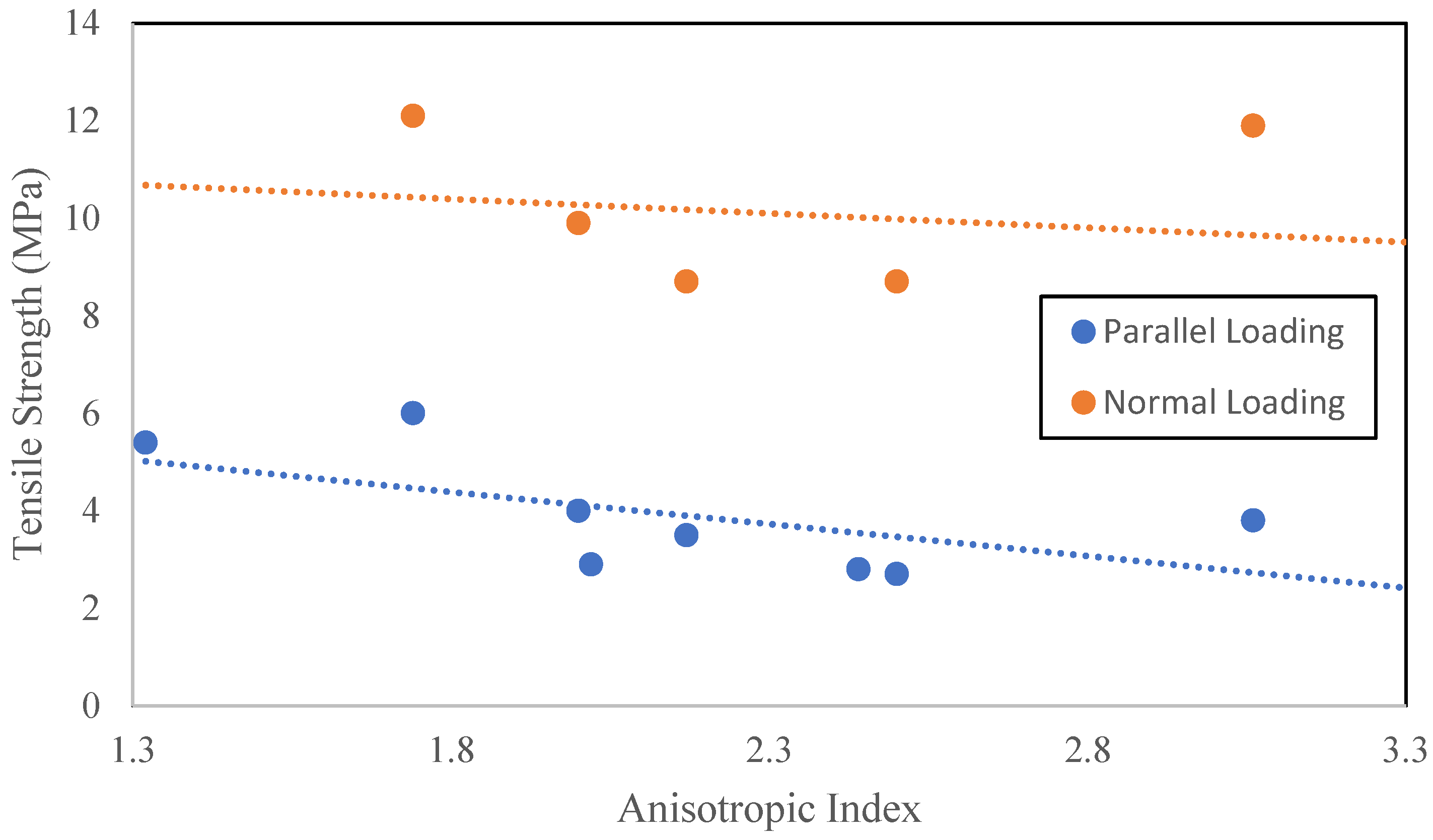
Anisotropy significantly affects the tensile strength of foliated rocks, like compressive strength. There are several methods to determine the tensile strength of foliated rocks, such as the direct tension test, Brazilian tensile test, ring test, pull-off test, bending test, etc. In the case that rocks are considered isotropic, the Brazilian tensile test provides satisfactory results; however, for anisotropic foliated rocks, no universal method has been devised yet to accurately determine their tensile strength [36]. The selection of a suitable method for determining the tensile strength of foliated rocks is beyond the scope of this review. Several studies have been carried out to investigate tensile strength variations with orientation angle [2,21,37,38,39,40,41,42,43,44,45]. Maximum indirect tensile strength was recorded at β = 90°, whereas minimum tensile strength was found at lower orientation angles. At β < 60°, weak planes or foliations considerably contribute to governing the tensile strength of foliated rocks [44]. In other words, less anisotropic effect signifies a larger tensile strength value. This behavior is attributed to the low cohesion between the foliations or less impact of preferably arranged phyllosilicate minerals [46]. Low cohesion refers to reduced binding strength between the foliations. As a result, rock tends to fracture or fail along these planes when subjected to loading. Saroglou and Tsiambaos [35] studied the effect of the anisotropic index on the tensile strength of foliated metamorphic rocks. They observed that, with an increase in tensile strength, anisotropic index reduces as shown in Figure 2. The anisotropic index for tensile strength can be expressed as follows:
I α = σ t = p a r a l l e l σ t = p e r p e n d i c u l a r
where I α is an anisotropic index, σ t = p a r a l l e l is tensile strength measured parallel to foliation, and σ t = p e r p e n d i c u l a r is tensile strength measured perpendicular to foliation.
Shear strength is one of the important parameters most widely used in design calculations to evaluate the behavior of rocks when failing in shear mode. In the case of foliated metamorphic rocks, sliding occurs along the preferred orientation of the weak plane. Apart from compressive and tensile strength, some studies were carried out to investigate the anisotropic effect on the shear strength of foliated rocks [34,35,45,47,48,49,50,51]. In order to study the anisotropic behavior of foliated rocks, the direct shear test is recommended; however, the sample preparation for this test is quite difficult. Therefore, empirical relationships were developed to cope with this problem. The Mohr-Coulomb equation is one of the most widely used models to find the shear strength of isotropic rocks in terms of cohesion and internal friction angle. However, the Mohr-Coulomb model does not fit well to predict the shear strength of foliated rocks at varying orientations of weak planes. There are two major limitations in this model: (1) strength response is linear and (2) there is no intermediate principal stress. Jaeger [34] introduced the single plane of weakness concept with varying cohesion between the inclined plane and constant internal friction angle to estimate the shear strength of rocks. Hoek and Brown 1980 presented the strength parameters m and s in their model depending on the orientation of weak planes. Both models [34,52] have the major drawback of assuming a constant friction angle with linearly varying cohesion along the plane of weakness. Later on, several modified nonlinear models under the multiaxial state of stress were developed to predict the shear strength of foliated rocks [53].
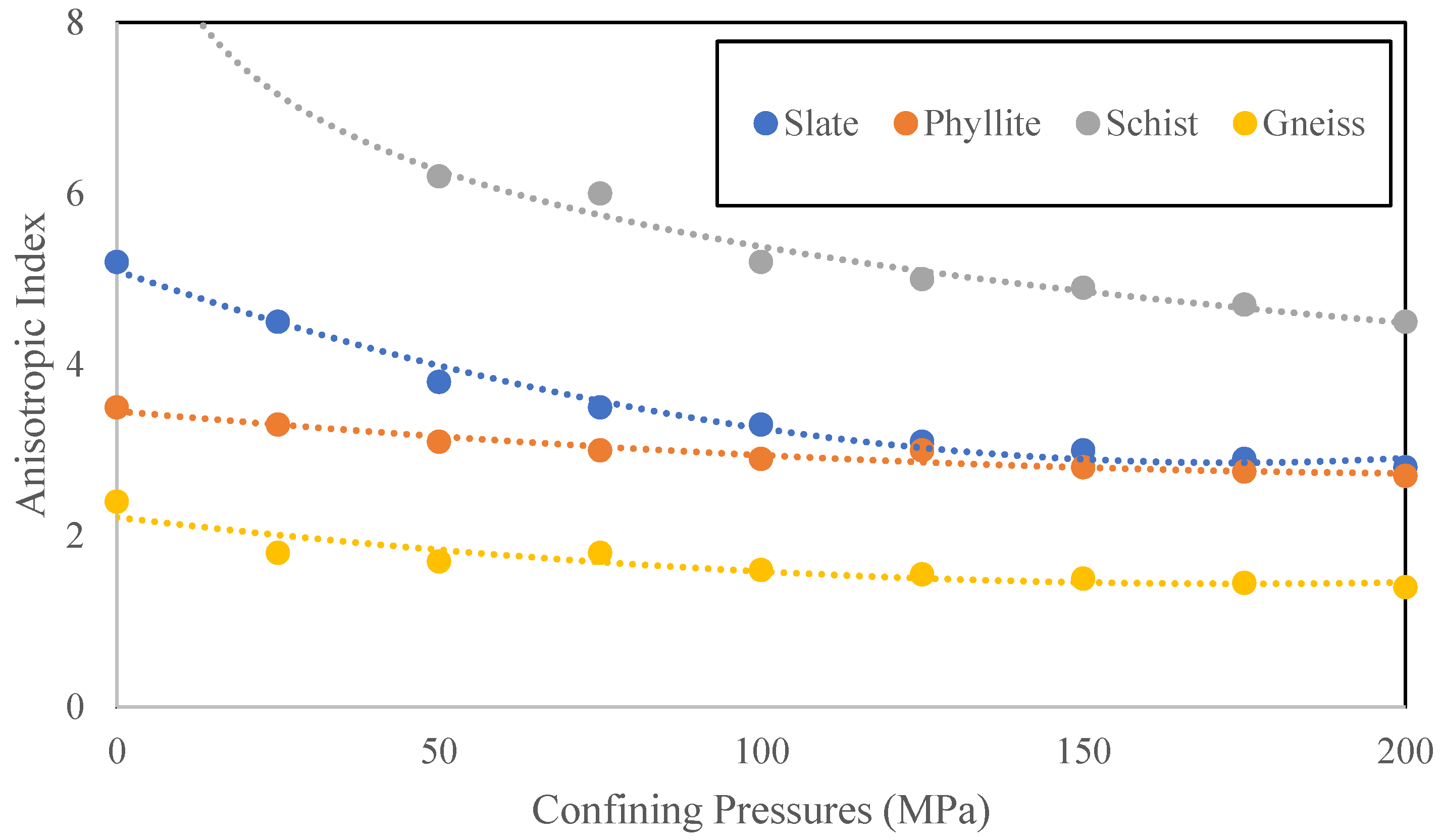
Shear strength varies with the orientation of foliations. Minimum shear strength was reported at intermediate angles 30° ≤ β ≤ 60°. In the case of the direct shear test, the shear strength was measured lower than the normal load when failure occurred along the weak planes and vice versa [51]. At a higher grade of foliation and phyllosilicate content, foliated rock exhibits lower shear strength. Anisotropy significantly affects the shear strength of foliated rocks either tested under direct shear or triaxial compression. Rock shear strength parameters (c and ϕ) can be determined using a triaxial compression test. In triaxial testing, increasing confining pressures reduces the anisotropic effect (see Figure 3). The strength of foliated rocks improves nonlinearly with confinement at different orientation angles. Minimum strength was observed at 30° ≤ β ≤ 45°with varying confining pressures [3]. Furthermore, Ramamurthy [8] reported an interesting behavior of phyllite under triaxial compression. The shear strength parameters of cohesion and internal friction angle varied inversely at particular orientations with increasing confinement.

3. Microstructural Characteristics

The microscopic properties of rocks, including mineral compositions and distribution, internal defects, microfracture patterns, intergranular or intragranular cracks, etc., are of great interest in terms of how they control the macroscopic failure of rocks subjected to external loading [56]. Foliated metamorphic rocks have the intrinsic characteristics of weak planes such as slab, schistosity, and gneissosity developed by the directional arrangements of minerals and microcracks under differential pressures. The directional arrangement of minerals (especially phyllosilicates) significantly affects the damage mechanism of foliated rocks [57]. The phyllosilicates are found elongated, preferably oriented, and accompanied by microcracks. Foliated metamorphic rocks generally consist of phyllosilicates and granular minerals. The phyllosilicates are characterized by a high specific surface area, weak strength, strong toughness, and platy morphology, whereas granular minerals have properties of high strength, poor toughness, resistance to weathering, and granular morphology [58]. The mineral distribution in foliated rocks can be either uniform or interlayer. Interlayer distribution is the result of high-grade metamorphism, and it has a significant effect on anisotropy as compared to uniform distribution [48,59].
Figure 4 illustrates the microstructural characteristics described by Yin [58] in their state-of-the-art review. The distribution of cracks in the matrix of foliated rocks is as follows: intragranular cracks in phyllosilicate mineral, directional cracks at the edge of phyllosilicate mineral, intragranular cracks in granular mineral, and boundary cracks at granular mineral. The plastic deformation or failure of phyllosilicate minerals under compression loading depends on the orientation angle between the weak plane and the major principal stress [36].
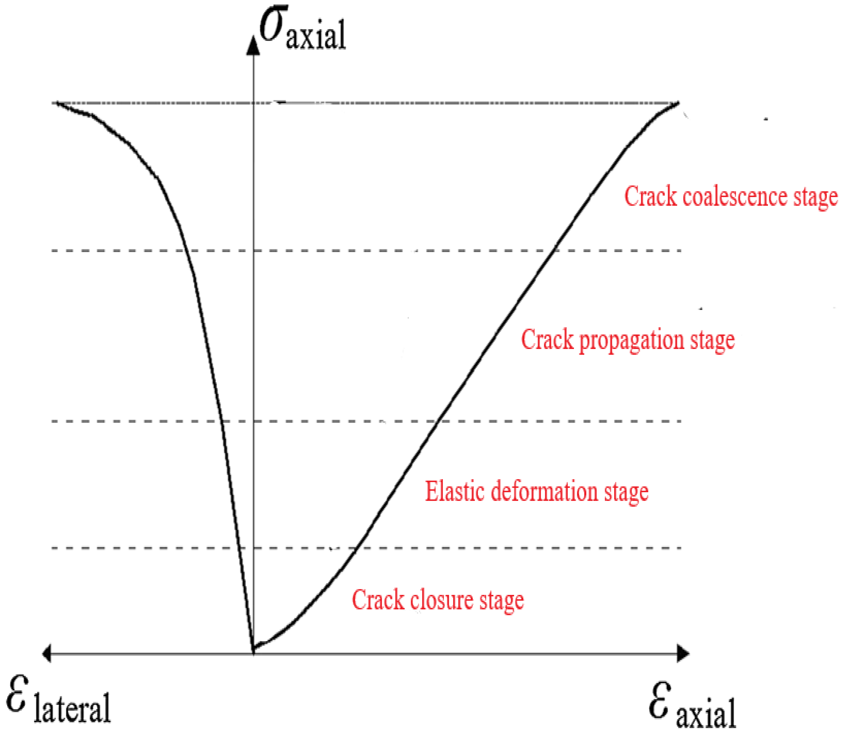
In ambient conditions, foliated rocks exhibit brittle behavior under compression loading. However, high confining pressure and temperature shift their behavior from brittle to ductile [60]. The orientation of weak planes in foliated rocks also alters the rocks’ behavior. In this case, however, we are discussing foliated rock behavior loaded normally. According to crack evaluation theory, a brittle rock subjected to loading can undergo different stages, including the crack closure stage, elastic deformation stage, crack propagation stage, crack coalescence stage, and peak failure stage. Figure 5 shows the different stages of rock behavior in terms of the stress–strain curve. In the crack closure stage, plastic deformation of pre-existing cracks occurs, which improves the rock’s stiffness, and a concave-up trend can be observed in the stress–strain curve [61]. In the elastic deformation stage, a linear relationship between stress and strain can be noted, as well as a gradual increase in the lateral stress–strain curve. In the crack propagation stage, the applied load exceeds the elastic threshold limit and starts the crack initiation process. Under continuous loading, the new cracks are propagated following the least-resistant path. In the crack coalescence stage, propagated cracks are aggregated and make definite weak planes along which the rock fails [62]. The lateral stress–strain curve shows a nonlinear trend, which means the rock is enduring more strain at minimum stress.

4. Damage Mechanism of Mica and Granular Minerals

Mica, a phyllosilicate mineral, is abundantly found in foliated metamorphic rocks. The spatial arrangement of mica plays a significant role in anticipating the behavior of foliated rock at the microscopic level. Several researchers [50,58,63,64,65,66,67,68,69,70,71] studied the damage characteristics of mica and its effect on the strength of foliated rocks. The deformation of mica under compression loading can be characterized by three processes: slipping, kinking, and fracturing. These processes initiate a cracking event in mica minerals.
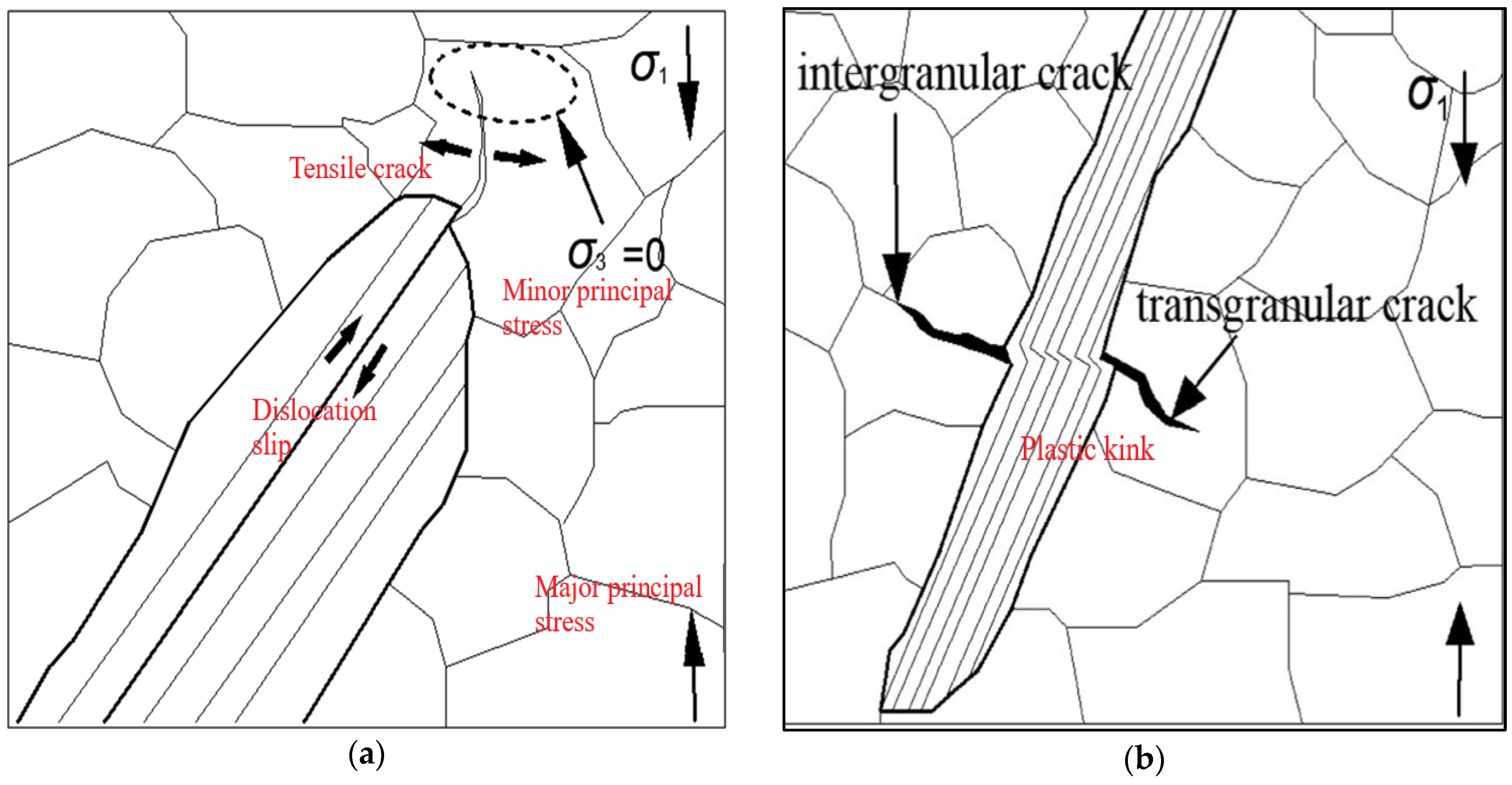
Mica has the physical characteristics of a cleavage plane. When shear stress exceeds the frictional resistance in a mica crystal, sliding occurs, and a high-stress concentration zone develops at the tip of the mica (see Figure 6a). When stress concentration overcomes the threshold limit of the surrounding granular minerals’ tensile strength, tensile cracks initiate [72]. Mica experiences maximum influence of shear stress at the orientation angle of β = 45°. Slippage can occur even at low shear stress because of low frictional resistance. That is why, at intermediate orientation angles β = 30°–45°, volume expansion was reported in the literature: because of dislocation slip and tension cracks [73]. There are two types of cracking events: shear failure along cleavage planes and tension cracks. For the stable growth of these cracks, the state of stress (i.e., no minor principal stress) must be the same at the tip of the mica and the tension crack [62]. In the case of confinement, the cracking event is ceased because of the variable state of stress at the mica tip and tension cracks. In addition, shear cracks intersect the cleavage planes at low angles to form a slippage wall [58]. Further modification of the high-density slippage leads to plastic kinking [74].
Yin [58] explained the two modes of plastic kink initiation. The plastic deformation of mica crystal forms a kink belt or kink boundary that initiates a cracking event either in mica or in adjacent granular minerals as shown in Figure 6b. Mode-1 kink initiation deals with the high-density slippage in mica and the shear failure of cleavage planes inside the kink belt. A low angle (i.e., < 5°) deflection was noted outside the kink belt due to the plastic deformation of mica [66]. At very high plastic deformation, when exceeding the threshold limit of plasticity, an intragranular cracking event initiates inside the mica crystal [69]. In the case of mode-2 kink initiation, stress concentration initiates grain boundary cracks or intragranular tension cracks in adjacent granular minerals. Rawling [73] observed that the lateral fracture and failure of mica with the increase in applied load is the result of stress generated by the plastic kink that overcomes the strength of mica.
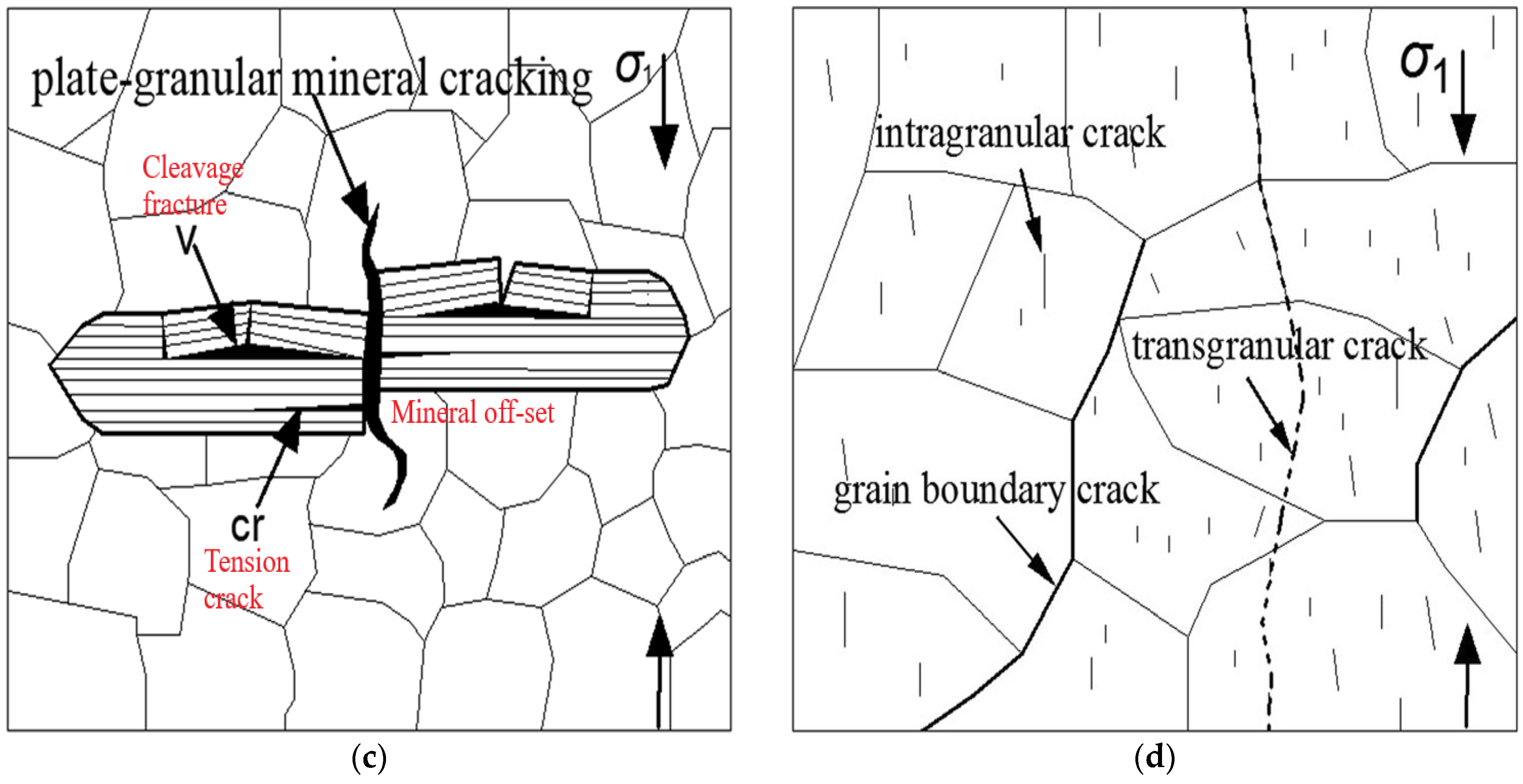
The fracturing of mica is a crack initiation event that can be characterized by voids or pores due to the opening of cleavage planes, intragranular tension cracks, and edge-oriented directional cracks splitting the mica from adjacent granular minerals [67]. A micron-level spacing between the tension cracks and cleavage plane opening can be chipped off under increasing applied load (see Figure 6c). Foliated rocks loaded normally β = 90° can have widespread fractures crossing the foliation planes [48].
Intergranular cracks and intragranular cracks contribute majorly to the crack propagation stage. In unconfined loading, intragranular tension cracks are initiated from the tip of the mica and propagate parallel to the direction of the major principal stress [72]. Grain boundary cracks are considered longer in terms of their propagated length. The stress at the tip of the boundary crack determines whether it will cease or move around the granular minerals [75]. Apart from grain boundary cracks, intragranular cracks propagate at shorter distances and cease at the grain boundary. There are several crack propagation modes reported in the literature depending on the orientation angle, loading rate, crack geometry, continuity, or discontinuity of the crack, etc. [76]. In recent years, Yin [58] studied crack patterns and the extent of fracture zones. They observed three different crack extension modes, named mode-1, mode-2, and mode-3 crack propagation. At a low orientation angle (β = < 15°), boundary crack extension belongs to mode-1 propagation, and the cracks propagate parallel to the direction of the major principal stress. Mode-2 crack propagation is observed when the orientation angle is set at β = 15°–75°. In this mode, grain boundary cracks and intragranular cracks develop a fracture zone that provides a fast and least-resistant path for crack extension (see Figure 6d). In mode-3 crack propagation, a large and widespread fracture zone develops at a high orientation angle (β = 75°–90°). Although the fracture zone provides the easiest path for crack extension, granular minerals, mica, or micro defects obstruct crack propagation.
In the crack aggregation stage, intergranular and intragranular cracks coalesce to form transgranular cracks that cross the grain boundary [72]. The intragranular cracks in granular minerals propagate at a shorter distance because grain boundaries and micro defects hinder their expansion. A gradually increasing applied load provides sufficient energy to cross this barrier. The high-density intragranular cracks and boundary cracks are integrated to make fracture zones along which rock can fail after peak strength [77]. Like crack propagation modes, unstable cracks are aggregated in different modes as reported in the literature [58]. In mode-1 crack aggregation, a small fracture zone develops, dominated by tensile cracks at the low orientation angle. A relatively large fracture zone develops in mode-2 crack aggregation at an intermediate orientation angle with high-density intragranular cracks and grain boundary cracks [48]. In mode-3 crack aggregation, a widespread and large fracture zone develops at a high orientation angle with tensile fractures crossing the foliation planes.

5. Damage Mechanism and Mode of Failures

Rock under compression loading exhibits various behavioral alterations such as nonlinear closure of pre-existing cracks, linear elastic deformation, plastic deformation, failure, and post-failure [7]. The plastic deformation stage contributes majorly to the failure of rock. In this stage, the initiation of a cracking event, propagation of cracks, and coalescence of cracks with micro defects form fracture planes along which rock fails after showing its peak strength. The growth of newly initiated cracks becomes unstable gradually as the deviatoric stress increases [58]. Rock is a heterogeneous material and an aggregate of different minerals. Each mineral has its specific mechanical characteristics and exhibits different behavior at the microscopic level. The damage mechanism of brittle rock can be characterized by stress localizations, the opening of grain boundaries, cleavage planes, intragranular cracks, pores, internal defects, etc. [22]. In the case of anisotropic foliated brittle rocks, the orientation angle (β) between deviatoric stress and foliation planes governs the direction of crack propagation. At the intermediate angle of 0° < β < 90°, the shear-slip failure or combined shear-tensile failure occurs along the plane of weakness [78]. The clusters of elongated phyllosilicate minerals (i.e., mica) and granular minerals form weak layers that integrate with microcracks and mineral defects such as opened cleavage planes. This coalescence along the plane of weakness causes shear-slip or combined shear-tensile failure.
The mineral defects or microcracks slanted to compression loading experience stress concentration at their tips. As a result, new cracks are initiated and propagated at the tip of the pre-existing defects. Rawling [73] and later Yin [22] investigated the reason for the damage mechanism of foliated rocks. They found that when deviatoric stress increases to a critical limit, then shear stress overcomes the frictional resistance between the two surfaces of the microcracks or flaky-mineral cleavage planes. Thus, sliding occurs between the surfaces, and tensile stress develops at the tip of the defect that initiates tensile wing cracks expanding in the direction of the major principal stress. After the release of tensile stress, any further increase in deviatoric stress initiates a secondary shear crack at the tip of the defect propagating in the direction of the major principal axis. The propagation and aggregation of these cracks define the mode of failure [79]. At peak strength, the unstable growth of tensile wing cracks and shear cracks produces shear-slip failure or combined shear-tensile failure.
The crack evaluation theory explains the damage mechanism of foliated rocks. The tensile wing cracks originating from the tip of the oriented phyllosilicate minerals play a significant role in the rock damage process [76]. However, secondary shear cracks initiated in later stages propagate crack aggregation. Overall, tensile wing cracks have a dominant effect on the rock damage process. The orientation of weak planes also governs the rate of rock damage. At an intermediate angle of 0° < β < 90°, shear-slip failure occurs at a faster rate than axial splitting failure (at a low orientation angle of β = 0°) or shear cross-cutting failure (at a high orientation angle of β = 90°) [22,80].
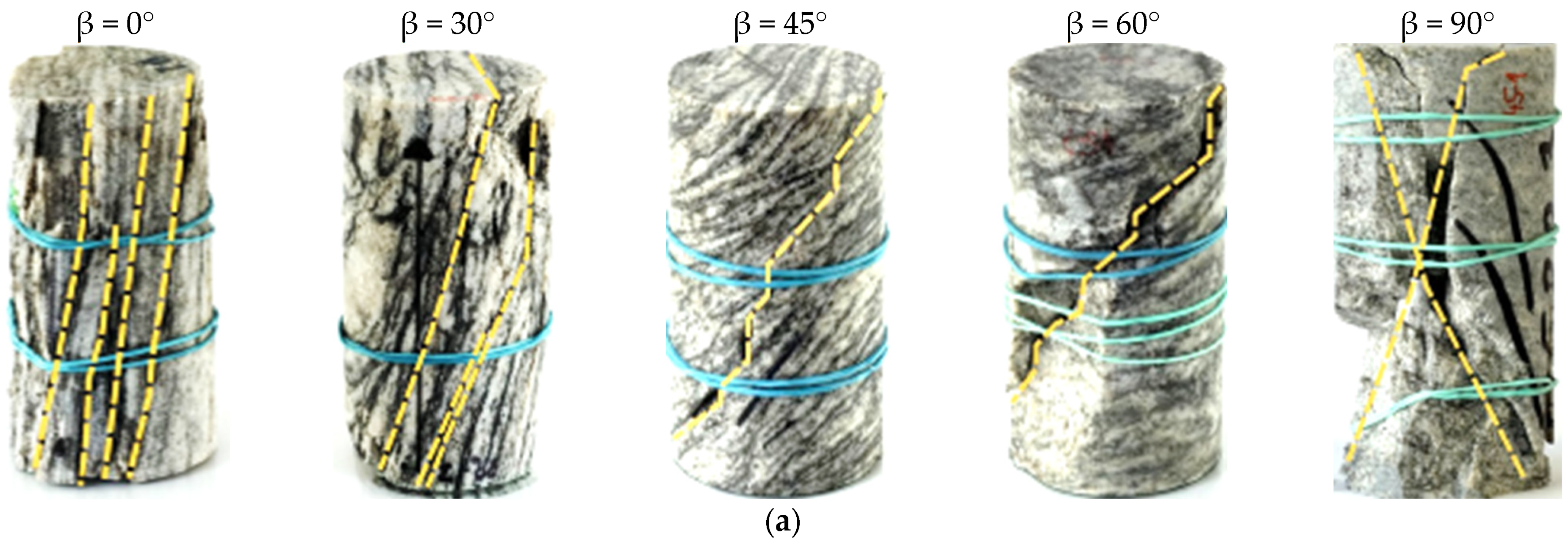
In the recent past, researchers observed different failure modes in foliated metamorphic rocks at varying orientation angles subjected to compression or tension loading [22,33,36,44,78,81,82,83,84,85,86,87]. In the case of unconfined compression loading, researchers observed the following failure modes: at β = 0°, tensile splitting of foliation planes with shear cracks, at 0° < β < 90°, shear-slip or shear-tensile failure along the major plane of weakness, and at β = 90°, single or conjugate shear failure cross-cutting the foliation planes (see Figure 7a). Rastegar [44] studied the failure modes in foliated rocks subjected to indirect tensile loading, such as the Brazilian tensile test. They noted the following failure modes: at β = 0°–30°, central crack with splitting tensile failure, at β = 30°–60°, slip in foliations or slip in foliations combined with central crack, and at β = 60°–90°, non-central crack cross-cutting the foliations (see Figure 7b).
In the case of the pull-off test, Weng [36] observed two failure modes: (1) smooth surface failure along the foliation planes, and (2) jagged surface failure because of interconnected pre-existing joints or microcracks. The pull-off test determines the tensile strength between foliations by pulling apart rock surfaces using an adhesive material [88]. The orientation angle between foliation planes and deviatoric stress is not the only key factor that controls the failure modes in foliated rocks. Rather, temperature variations, differential stresses, and confining pressures also play a significant role. For example, at low temperatures, minerals exhibit brittle failure, whereas at high temperatures, ductile mechanisms dominate, such as dislocation, creep, recrystallization, etc. High differential pressures at low temperatures can lead to cataclastic flow in minerals. Under triaxial compression loading, the high confining pressure obstructs the propagation of initiated cracks and shifts the rock’s behavior from brittle to ductile [17,26,89]. Table 2 shows recent developments regarding the failure modes of foliated rocks.

6. Failure Criteria

Several failure criteria have been developed to estimate rock failure when subjected to applied loading. In simple words, a failure criterion is an approach that predicts how and when a rock will fail [91]. No universal rock failure criterion has been formulated yet that can be applied to solve all rock engineering problems [53]. The rock mechanics community has suggested various failure criteria by considering rock as an isotropic, anisotropic, transversely isotropic, transversely anisotropic, continuous, discontinuous, brittle, and ductile material (see Table 3). This review only covers the developments in failure criteria for brittle anisotropic foliated rocks. These rocks exhibit a high degree of anisotropy and nonlinear failure response because of the preferred orientation of foliations [16].
Jaeger [34] introduced the concept of an isolated plane of weakness to study anisotropic behavior. He observed failure along the weakness plane and in the rock matrix as well. Jaeger’s work was inspired by the Mohr-Coulomb failure criteria and considered the orientation of the weakness plane related to loading direction with a constant friction coefficient. It holds good for a single weakness plane; however, in the case of highly foliated rocks, this criterion fails to fit linear equations on the nonlinear response of such foliated rocks. The criterion can be expressed mathematically as follows:
σ 3 σ 1 = 2 σ s 2 σ 1 t a n ϕ t a n ϕ t a n 2 ϕ + 1
where σ 3 and σ 1 are the principal stresses, σ s is cohesive strength, and t a n ϕ is the constant friction coefficient. Mclamore and Gray [17] presented a modified version of Jaeger’s criterion and suggested varying friction coefficients with the orientation angle of weakness planes:
σ s = A B [ C o s 2 β m i n β ] n
t a n ϕ = C D [ C o s 2 β m i n β ] n
where A and B are constants at a range of 0° ≤ β m i n β or β β m i n < 90°, C and D are constants at a range of 0° ≤ β β m i n , β m i n is the angle at which strength is minimum, β is the angle for which strength is being predicted, and n is the anisotropy factor whose value varies from 1 to 6. Jaeger and Cook [101] proposed another criterion with varying cohesion, friction coefficient, and orientation angle. No intermediate principal stress was considered as a significant parameter in this criterion. Mathematically, it can be expressed as follows:
σ 1 = σ 3 β + 2 ( σ s + σ 3 t a n ϕ ) β s i n 2 β ( 1 t a n ϕ t a n β )
Zienkiewicz and Pande [102] introduced a multilaminate constitutive failure criterion that models the behavior of foliated rocks with multiple planes of weakness (such as foliations or bedding planes). The criterion considers the combined effect of both the intact material and the discontinuities in defining the overall failure of the rock. It can be written as follows:
F = i = 1 n ( f i )
where F is the overall failure criterion, f i refers to the failure criterion for an ith plane, and n represents the number of planes of weakness. To account for material heterogeneity, Pijaudier-Cabot and Bazant [103] modified the classical Mohr-Coulomb failure model ( τ = c σ n t a n φ )   and developed a nonlocal Mohr-Coulomb failure criterion with softening. In this criterion, a strain-softening behavior with a nonlocal effect was incorporated to avoid localization and mesh dependency issues. Mathematically, it can be described as follows:
c ϵ p = c o ( 1 ϵ p ϵ p o )
φ ϵ p = φ o ( 1 ϵ p ϵ p o )
where c and φ are cohesion and friction angle, respectively, at accumulated plastic strain. c o and φ o are initial cohesion and friction angle, respectively. ϵ p is the accumulated plastic strain and ϵ p o is the plastic strain at the start of the failure. Hoek and Brown [52] developed a failure criterion for brittle isotropic intact rocks and introduced material constants m (it represents the material’s intrinsic strength), s (it is related to the material’s intact compressive strength and degree of fracturing), and α (it deals with non-linearity in failure envelope) into the equation. For anisotropic rocks, these material constants were adjusted as the orientation angle β varies related to the deviatoric stress:
σ 1 = σ 3 + σ c i ( m σ 3 σ c i + s ) α
where σ c i is the compressive strength of the material. Ramamurthy [30] proposed a criterion to estimate the strength of anisotropic rocks and their nonlinear response as follows:
σ 1 = σ 3 + σ 3 B ( σ c β σ 3 ) α
where σ c β is the compressive strength at a particular orientation of angle β . The parameters α and B are functions of anisotropy orientation. Singh [104] proposed a modified failure criterion and tried to fit the nonlinear response of highly foliated rocks. They used intermediate principal stress that was not considered in the previous criteria:
σ 1 σ 3 = σ u + s i n ϕ p ( σ 2 + σ 3 ) 1 s i n ϕ p
where σ 1 , σ 2 and σ 3 are major, intermediate, and minor principal stresses, respectively; σ u is uniaxial compressive strength, and ϕ p is peak friction angle. Tien [105] proposed a new failure criterion that consists of strength parameters of discontinuity and material. They observed two failure modes in this criterion: sliding mode and non-sliding mode. This criterion was derived from Jaeger’s criterion [34] and Hoek and Brown’s failure criterion [52] as follows:
S 1 ( β ) S 1 ( 0 ° ) = σ 1 β σ 3 σ 1 ( 0 ° ) σ 3 = k s i n 4 β + k c o s 4 β + 2 n k s i n 2 β c o s 2 β
where S is the strength parameter, k = S 1 ( 0 ° ) S 1 ( 90 ° ) is the strength ratio, and n is the transversal anisotropy parameter. In this criterion, seven parameters are involved based on the strength of discontinuity and rock matrix. Saroglou and Tsiambaos [106] modified the Hoek and Brown criterion by introducing an anisotropy-related parameter, k β . The new parameter controls the nonlinear fitting of the failure envelope. It can be expressed as follows:
σ 1 = σ 3 + σ c β ( k β m σ 3 σ c β + 1 )
Saeidi [53] modified Rafiai’s failure criterion [107] for transversely isotropic rocks. Rafiai proposed this criterion for isotropic rocks to predict their ductile strength subjected to a multiaxial state of stress. Saeidi’s failure criterion is as follows:
σ 1 = σ 3 + σ c β 1 + C σ 3 σ c β α β + D σ 3 σ c β
where σ c β is the orientation angle, C and D are the material constants, and α β is the strength reduction parameter related to the anisotropy. In the recent past, Yin [22] developed linear failure criteria for foliated rocks under two failure modes: shear slip failure and macro shear failure. The shear slip failure occurred at an intermediate orientation angle β = 15°–60°. The crack initiation stress was found close to the shear slip failure and mathematically can be expressed as follows:
σ c i = σ c i m i n 1 + f 2 f s i n 2 β f ( 1 c o s 2 β )
where σ c i m i n is the minimum stress for crack initiation and f is the anisotropy-related factor. The macro shear failure was observed at the orientation angles β = 0°–15° and β = 60°–90°, with strength factor S f ( β ) S f ( 0 ° ) and S f ( β ) S f ( 90 ° ) , respectively. Based on Tien’s failure criterion, Yin [22] proposed a modified failure criterion for macro shear failure as follows:
S f ( β ) S f ( 90 ° ) = k k s i n 4 β + 2 n s i n 2 β c o s 2 β
S f ( β ) S f ( 0 ° ) = 1 c o s 4 β + 2 n s i n 2 β c o s 2 β
The above-mentioned failure criteria were proposed under uniaxial or triaxial compression loading. However, researchers have developed several failure criteria for foliated rocks under tensile loading. Hobbs [108] and Barron [109] worked on Griffith’s theory and modified Griffith’s theory, respectively. They deduced an anisotropic failure criterion under tensile conditions as follows:
σ t ( β ) = 2 σ t b cos β ( 1 c o s β )       ,       0 ° β β σ t m                                                   ,       β β 90 ° cos β 1 + cos β = 2 σ t b σ t m
where σ t ( β ) is the tensile strength at a particular orientation angle β between the foliation plane and deviatoric stress. β is the critical angle, σ t b and σ t m are tensile strength of the foliation plane and rock matrix. Nova and Zaninetti [38] proposed a failure criterion for foliated rocks subjected to direct tensile stress as follows:
σ t ( β ) = σ t b σ t m σ t b s i n 2 β + σ t m c o s 2 β
t a n β = ( σ t m σ t b ) s i n β c o s β σ t b s i n 2 β + σ t m c o s 2 β
where t a n β estimates the orientation of the failure plane. This criterion can be validated by an indirect tensile strength dataset of different foliated metamorphic rocks. Liao [40] modified the Hobbs-Barron failure criterion because it did not provide a good understanding at a higher orientation angle β . The extended failure criterion is as follows:
σ t ( β ) = 2 σ t b cos β ( 1 c o s β )       ,       0 ° β β σ t m ( 1 h cos 2 β ) ,       β β 90 ° cos β 1 + c o s β = 2 σ t b σ t m
where h is the material parameter influenced by anisotropy. Li and Aubertin [110] presented three parameters based on a simple failure criterion that can be applied to both direct and indirect tensile strength datasets of foliated rocks:
σ t β = σ t b + ( σ t m σ t b ) s i n n β
where n = σ t m σ t b is the tensile stress ratio depending on the material and weak plane strengths. The relationship for the estimation of indirect tensile strength of isotropic rocks does not provide reasonable results for anisotropic foliated rocks. Claesson and Bohloli [111] proposed modified failure criteria for anisotropic rocks as follows:
σ t = 2 P π d t E E 4 c o s 2 β c o s 4 β 4 E E 2 1 G 2 ν E 1
where P is deviatoric stress, d and t are the diameter and thickness of the disc, respectively, and E E   G , and ν are elastic moduli, shear modulus, and Poisson’s ratio, respectively. Like Jaeger’s single plane of weakness criterion under compression loading, Lee and Pietruszczak presented a single plane of weakness failure criterion under tensile conditions. Later, they proposed a more simplified criterion to predict the tensile strength of transversely isotropic rocks as follows [112]:
σ t β = ( σ t m + σ t b ) 2 σ t m σ t b 2 c o s 2 β

7. Discontinuum Modeling and Simulation

Under a gradual increase in stress, rocks experience microcracking events such as crack initiation, propagation, and aggregation that lead to the macro failure of material [113]. Microstructural characteristics not only govern the grains’ behavior, but also significantly affect the macro mechanical behavior of rocks. Numerical simulation provides deep insight into the failure processes by considering the rock as a continuous or discontinuous material. Computer-assisted numerical modeling helps to adequately present the grains and their microscopic properties. Grain characteristics such as grain shape, grain size, grain sorting, and grain contact can be used to model rock failure processes in the laboratory and field [114].
Numerical modeling is typically categorized into either continuum or discontinuum approaches. Continuum-based methods such as FEM (finite element method), FDM (finite difference method), BEM (boundary element method), etc., are widely used to model up-scale problems. For example, Pant [115] used implicit finite element codes to simulate the rock slope failure in a foliated rock mass. Similarly, Bouzeran [116] studied the effect of the buckling mechanism and heterogeneity in foliated rocks using numerical back analysis based on the continuum method, i.e., FLAC3D. In another study, Wang [117] investigated the failure mechanism in a circular tunnel excavated in transversely isotropic rocks using continuum-based RFPA (realistic failure process analysis) codes. This method uses an elastic damage model to determine the tensile and shear failures following the maximum shear failure criterion and Mohr-Coulomb criterion, respectively. Conventional continuum methods use macro strain-softening constitutive models which cannot address the influence of strain localization, nonlinearity, and micro discontinuities due to the scale effect [118,119]. This is the major drawback of traditional continuum methods while simulating the failure mechanism of anisotropic foliated rocks from a small-scale perspective. However, this problem can be overcome using an improved continuum model such as a combined continuum-discontinuum method, or a regularized continuum method, i.e., FEM codes with the Cosserat model.
In the context of the discontinuum modeling approach, rock is represented by an aggregate of discrete blocks and discontinuities. It has a competitive edge over the continuum modeling method because of realistic assumptions and no requirement for pre-defined constitutive models [114]. For instance, continuum methods like FEM can be used to model the damage mechanism of anisotropic foliated rocks based on the equations derived from continuum damage mechanics (CDM). A CDM is a constitutive theoretical framework that describes the relationships between stress, strain, and damage in material [120,121,122].
The anisotropy and heterogeneity both are scale-dependent. At a smaller scale (millimeters to centimeters), foliated metamorphic rocks such as schist or gneiss demonstrate a preferred orientation of minerals, and this mineral alignment leads to direction-dependent properties such as variations in strength, stiffness, and deformation. At this point, anisotropic behavior is more dominant than heterogeneity. However, at a bigger-picture scale (meters to kilometers), rock mass is comprised of different rock types or minerals with no specific direction-dependent characteristics and looks more heterogeneous instead of anisotropic. In discontinuum methods, heterogeneity can be modeled by varying the properties (e.g., stiffness, strength, or friction) of individual elements. Similarly, anisotropy can be modeled by assigning direction-dependent properties such as planes of weakness. Discontinuum methods are capable of modeling both heterogeneity and anisotropy, with the dominant behavior being scale-dependent and influenced by the resolution of the model. The heterogeneity of rock can be represented by the discrete particles or grains of various shapes such as disks, spheres, ellipses, cubes, triangles, polygons, and polyhedrons [123,124,125]. Among all grain shapes, polygonal and polyhedron shapes are considered more realistic, and Voronoi tessellation is commonly used for the generation of these shapes to model the microscopic behavior of grains [126].
In grain-based modeling (GBM), the discrete grains or blocks can be elastic, plastic, rigid, deformable, breakable, and unbreakable. The micromechanical properties of grains and their contacts are varied depending on the types of grains [127]. For example, in rock failure simulations, tetrahedral grains exhibit smooth failure due to the shear failure at contacts. Conversely, polyhedral grains show relatively rough failure because of the dominant tensile failure at contacts [128]. For the sake of the easiest computation, grains are considered elastic, rigid, and unbreakable, and rock behavior is modeled based on grain contacts. Each grain has specific characteristics in terms of computational efficiency and model calibration [129]. Strictly speaking, this assumption is not realistic, since grains can practically break and deform. For the modeling of rock failure using realistic assumptions, more computational time is required with higher complexity.
In the discrete element method (DEM), two modeling approaches are widely used: bonded particle modeling (BPM) and grain-based modeling (GBM). In BPM, the mechanical behavior of rocks is simulated by considering the rock as an aggregate of circular grains tightly packed at their contacts [114]. In GBM, polygonal or polyhedral grains are considered to model the deformational behavior of rocks using realistic assumptions. BPM-based modeling methods cluster particle modeling and clumped particle modeling are used to represent breakable and unbreakable grains, respectively. Some issues are reported in the literature such as low UCS/UTS ratio, low friction angle, and poor strength due to the use of traditional DEM approaches [130]. These issues are resolved in advanced modeling methods using grain interlocking, breakable contacts, and deformable grains. For effective numerical modeling with less complexity and computational time, grain and contact characteristics are specially focused. Table 4 shows the necessary parameters for grain and contact used in numerical modeling and simulation.
The DEM is a powerful tool to simulate the deformational behavior of anisotropic foliated rocks. It is an advantageous approach to evaluate the micro mechanisms of rock damage processes. The applications of numerical modeling have extended from a laboratory scale to the field, in which jointed/discontinuous rock mass is modeled using a discrete fracture network (DFN) approach. Researchers have made several attempts to simulate the strength behavior of anisotropic foliated rocks (see Table 5).
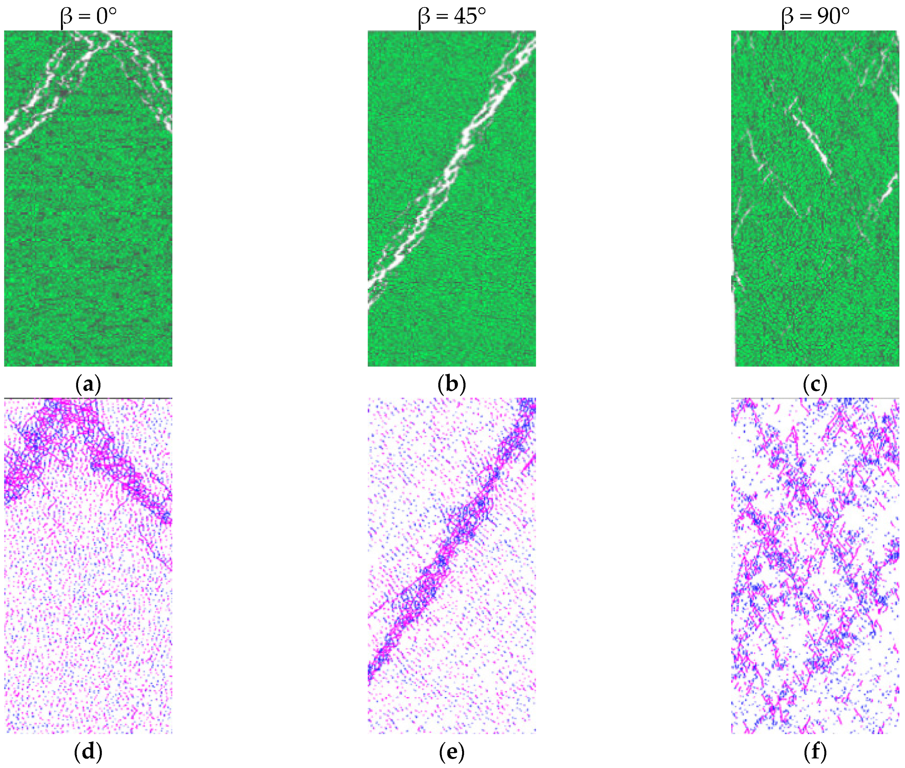
Shang [140] investigated the anisotropic behavior of incipient foliation planes under tensile loading using bonded particle modeling. They observed a significant effect of foliation plane orientation and spacing on the failure mechanism of the rocks. Yao [141] studied the damage and failure mechanisms in anisotropic brittle rocks. They used the rigid block spring method (RGBM) and the Voronoi tessellation approach to consider rock as an assemblage of rigid blocks. Both damage and failure were controlled by the breakable and deformable contacts. They noted tensile and shear failure in rocks as illustrated in Figure 8. Debecker and Vervoort [142] conceptualized a model to study fracture patterns in foliated rocks using 2D discrete element modeling. Chiu [143] simulated the anisotropic behavior of jointed rock mass using bonded particle modeling (BPM) and modified smooth joint modeling (SJM). Instead of using a constant value of friction angle, they studied the effect of joint roughness and orientation on shear strength. The BPM and modified SJM were used to simulate block contact and sliding effect respectively.
DDA (discontinuous deformation analysis) is a discontinuum modeling method like DEM which is used to simulate the mechanical behavior of rocks having complex discontinuities such as joints, fractures, weak planes, and other defects [144]. This approach is relevant to foliated metamorphic rocks, which demonstrate large deformations and patterns of discontinuities due to the preferred orientation of their weak planes and joints. DDA is a discrete numerical method that considers rock as an aggregate of rigid or flexible blocks [145]. Unlike continuum approaches, DDA assumes the discontinuities in the rock material, making it a suitable method to model the behavior of discontinuous rocks where disruptions significantly control the failure processes. The behavior of discrete blocks and the interactions between them are governed by rigid body dynamics and contact mechanics respectively [146]. This method can be salubrious for the modeling of foliated rocks in various aspects. It can explicitly model geometries, grain contacts, orientations, joints, and foliated planes. It can handle the issues related to large deformations caused by the shear, tension, and compression forces which are common in foliated metamorphic rocks due to local or regional tectonic activities. Furthermore, DDA provides insights into the deformation mechanism explained by the detailed analysis of block displacements, rotations, and contact forces [147].
DDA is a displacement-based discontinuum method that simulates the behavior of discrete blocks. It works on an iterative process within a stepwise time loop to reach the equilibrium condition under contact constraints by employing displacement as a variable. DDA is a method that uses energy to solve problems with moving blocks. It can be derived using the principle of minimum potential energy or Hamilton’s principle [148]. Once the equations of motion are broken down into smaller steps, a special time marching scheme called Newmark is used to solve them. The way blocks interact with each other is determined by equations that consider how much they overlap and the friction between them. DDA uses a step-by-step approach to solve for the large movements of the blocks. The blocks are considered to be simply deformable. Because DDA includes the forces caused by the blocks’ mass, it can be used to solve problems with moving blocks in a dynamic way.
DDA has been used to solve several rock engineering problems related to foliated rocks. These problems include slope instability, underground excavation, rockfall hazard, seismic response analysis, etc. In the case of rock slope stability analysis, DDA can be used to model failure mechanisms such as wedge failure, toppling, and sliding [149]. Tunneling and underground excavation in foliated rocks are challenging tasks. DDA can effectively simulate excavation-related processes including stress redistribution, failure along discontinuities, block dislodgement, and support system requirements [150]. This method can be utilized to model the triggering and propagation of rockfall in a terrain dominated by foliated rocks [151]. Furthermore, the seismic response of rock mass in terms of ground motion amplification can be assessed and simulated using improved DDA methods [152].
To develop significant DDA models for foliated metamorphic rocks, detailed geological data are needed, including rock strength parameters, mineralogy, geometry and orientation of foliated planes, and characteristics of discontinuities. DDA modeling can be complex, particularly for up-scaled problems. For accurate results, it is important to truly simulate the mechanical response of foliated rocks. Improving DDA by combining with continuum modeling methods can solve several complex problems in metamorphic rocks. Advancements in computational resources will develop better constitutive models for foliated rocks and thus discontinuum methods can be applied to larger and more complex rock mechanics problems.

8. Conclusions

This paper investigates the effect of anisotropy on the strength of foliated metamorphic rocks in terms of their microstructural characteristics and macromechanical behavior. It covers the literature review of recent and past experimental findings to highlight the major factors that considerably affect the mechanical behavior of foliated rocks. The engineering behavior of foliated rocks can be ascertained by addressing the following aspects: the degree of anisotropy, orientation of weak planes, mineral composition, rock fabric, internal defects, type of loading, loading rate, failure processes, theoretical and experimental framework, and numerical simulation.
The anisotropic behavior of metamorphic rocks is the result of the preferable orientation of phyllosilicate minerals along with the pre-existing microcracks in granular minerals that form weak layers in the rock matrix. The weak planes’ orientation angle (β) relative to the deviatoric stress governs the strength behavior of foliated rocks. In the literature, higher compressive strength is reported at β = 0° or 90°, whereas lower compressive strength is noted between β = 0° and 90°. An anisotropic behavior in terms of compressive strength versus β can be U-shaped, Shoulder-shaped, or Undulatory-shaped. In the case of indirect tensile loading, minimum strength is found at lower orientation angles due to axial splitting. Indirect tensile strength shows an inverse relationship with anisotropic index (i.e., the ratio of parallel tensile strength to normal tensile strength). An appreciated tensile strength is found at β = 90° because there is less of an anisotropic effect. Anisotropy in foliated rocks considerably affects the shear strength parameters (c and ϕ ) either determined by direct shear test or triaxial compression test. At β = 30°–60°, minimum shear strength is observed due to shear-slip failure along the foliation planes.
The macroscopic anisotropic behavior of foliated rocks is based on their microstructural characteristics. The microcracks in the quartz-feldspar matrix and the arrangement of phyllosilicate minerals such as mica majorly contribute to evaluating rock strength anisotropy. Foliated rocks subjected to compression loading undergo various stages: the crack closure stage, elastic deformation, crack initiation stage, crack propagation stage, and crack aggregation stage. The crack initiation stage may result from dislocation slip, plastic kinking, and fracturing in mica crystals. These microscopic alterations localize the tensile stress at the tip of the mica from where tensile wing cracks initiate and propagate sub-parallel to the deviatoric stress. On further increase in applied load, shear cracks initiate at the tip of mica, propagate at longer distances, and aggregate to form a network of cracks. The unstable growth of shear/tensile cracks reduces stiffness and ultimately the rock fails.
The weak planes’ orientation angle related to deviatoric stress controls the mode of failure in foliated rocks. At a low orientation angle β = 0°–15°, axial splitting is prominent due to the lack of confinement and failure along foliations. However, increasing confinement ceases the propagation of tensile wing cracks and consequently enhances rock strength. At intermediate orientation angle β = 15°–60°, shear-slip failure occurs along the foliation planes because of the weak interbedded layers. At high orientation angles β = 60°–90°, single or conjugate shear failure occurs across the foliations due to the integration of shear-slip and tensile failures.
Several empirical and mathematical failure criteria have been formulated to estimate the anisotropic strength of foliated rocks. They are useful, but, over the years, the applications of discontinuum methods have been getting attention globally in simulating the strength behavior of foliated rocks at a smaller scale. DEM (discrete element method) and DDA (discontinuous deformation analysis) both are widely used discontinuum approaches. They consider the material as an assemblage of discrete blocks. Many DEM models, such as the bonded particle model (BPM), grain-based model (GBM), flat joint model (FJM), smooth joint model (SJM), hybrid finite discrete element model (FDEM), etc., are used in practice to solve rock simulation-related problems. The crux of this modeling approach is to evaluate the elastic and strength behaviors of grains and their contacts. The discontinuum simulations have been effectively utilized in the laboratory and at the upscaled level to solve rock engineering problems.

Author Contributions

Conceptualization and Original Draft Preparation, U.W.; writing—review and editing, U.W., M.U.Q., S.S. and A.M.R.; review and correspondence H.M.A.R. All authors have read and agreed to the published version of the manuscript.

Funding

This research received no external funding.

Conflicts of Interest

The authors declare that they have no potential conflicts of interest regarding this research work.

References

  1. Bagde, M.N. An investigation into strength and porous properties of metamorphic rocks in the Himalayas: A case study. Geotech. Geol. Eng. 2000, 18, 209–219. [Google Scholar] [CrossRef]
  2. Hoek, E. Fracture of anisotropic rock. J. S. Afr. Inst. Min. Metall. 1964, 64, 501–518. [Google Scholar]
  3. Nasseri, M.H.; Rao, K.S.; Ramamurthy, T. Failure mechanism in schistose rocks. Int. J. Rock Mech. Min. Sci. 1997, 34, 219-e1. [Google Scholar] [CrossRef]
  4. Özbek, A. Variation of Schmidt hammer values with imbrication direction in clastic sedimentary rocks. Int. J. Rock Mech. Min. Sci. 2009, 46, 548–554. [Google Scholar] [CrossRef]
  5. Heng, S.; Guo, Y.; Yang, C.; Daemen, J.J.; Li, Z. Experimental and theoretical study of the anisotropic properties of shale. Int. J. Rock Mech. Min. Sci. 2015, 74, 58–68. [Google Scholar] [CrossRef]
  6. Ahmed, M.F.; Waqas, U.; Arshad, M.; Rogers, J.D. Effect of heat treatment on dynamic properties of selected rock types taken from the Salt Range in Pakistan. Arab. J. Geosci. 2018, 11, 728. [Google Scholar] [CrossRef]
  7. Waqas, U.; Ahmed, M.F. Investigation of strength behavior of thermally deteriorated sedimentary rocks subjected to dynamic cyclic loading. Int. J. Rock Mech. Min. Sci. 2022, 158, 105201. [Google Scholar] [CrossRef]
  8. Ramamurthy, T.; Rao, G.V.; Singh, J. Engineering behavior of phyllites. Eng. Geol. 1993, 33, 209–225. [Google Scholar] [CrossRef]
  9. Bozkurt, E.; Oberhänsli, R. Menderes Massif (western Turkey): Structural, metamorphic and magmatic evolution—A synthesis. Int. J. Earth Sci. 2001, 89, 679–708. [Google Scholar] [CrossRef]
  10. Garzón, E.; Sánchez-Soto, P.J.; Romero, E. Physical and geotechnical properties of clay phyllites. Appl. Clay Sci. 2010, 48, 307–318. [Google Scholar] [CrossRef]
  11. Karaman, K.; Kesimal, A.; Ersoy, H. A comparative assessment of indirect methods for estimating the uniaxial compressive and tensile strength of rocks. Arab. J. Geosci. 2015, 8, 2393–2403. [Google Scholar] [CrossRef]
  12. Tursi, F. The key role of µ H2O gradients in deciphering microstructures and mineral assemblages of mylonites: Examples from the Calabria polymetamorphic terrane. Mineral. Petrol. 2022, 116, 1–14. [Google Scholar] [CrossRef]
  13. Yin, X.; Huang, Y.; Zhang, A.; Lei, Y. Effect of Fabric Factors on the Mechanical Behavior of Foliated Rocks: A Particle Flow Approach. Geotech. Geol. Eng. 2023, 41, 1031–1047. [Google Scholar] [CrossRef]
  14. Özbek, A.; Gül, M.; Karacan, E.; Alca, Ö. Anisotropy effect on strengths of metamorphic rocks. J. Rock Mech. Geotech. Eng. 2018, 10, 164–175. [Google Scholar] [CrossRef]
  15. Goshtasbi, K.; Ahmadi, M.; Seyedi, J. Anisotropic strength behaviour of slates in the Sirjan-Sanadaj zone. J. S. Afr. Inst. Min. Metall. 2006, 106, 71–75. [Google Scholar]
  16. Askaripour, M.; Saeidi, A.; Mercier-Langevin, P.; Rouleau, A. A review of relationship between texture characteristic and mechanical properties of rock. Geotechnics 2022, 2, 262–296. [Google Scholar] [CrossRef]
  17. Mclamore, R.; Gray, K.E. The mechanical behavior of anisotropic sedimentary rocks. J. Eng. Ind. 1967, 89, 62–73. [Google Scholar] [CrossRef]
  18. Singh, J.; Ramamurthy, T.; Venkatappa Rao, G. Strength anisotropies in rocks. Indian Geotech. J. 1989, 19, 147–166. [Google Scholar]
  19. Kwasniewski, M.A. Mechanical behavior of anisotropic rocks. Compr. Rock Eng. 1993, 1, 285–312. [Google Scholar]
  20. Nasseri, M.H.B.; Rao, K.S.; Ramamurthy, T. Anisotropic strength and deformational behavior of Himalayan schists. Int. J. Rock Mech. Min. Sci. 2003, 40, 3–23. [Google Scholar] [CrossRef]
  21. Cho, J.W.; Kim, H.; Jeon, S.; Min, K.B. Deformation and strength anisotropy of Asan gneiss, Boryeong shale, and Yeoncheon schist. Int. J. Rock Mech. Min. Sci. 2012, 50, 158–169. [Google Scholar] [CrossRef]
  22. Yin, X.; Zhang, Y.; Lei, Y.; Wang, L. Linear failure criterion for estimating the compressive strength of brittle foliated rocks in response to the loading direction. Bull. Eng. Geol. Environ. 2022, 81, 189. [Google Scholar] [CrossRef]
  23. Deklotz, E.J.; Brown, J.W.; Stemler, O.A. Anisotropy of a schistose gneiss. In Proceedings of the ISRM Congress, Lisbon, Portugal, 25 September–1 October 1966; p. ISRM-1CONGRESS. [Google Scholar]
  24. Brown, E.T. Shear strength characteristics of Delabole slates. In Proceedings of the Conference on Rock Engineering, New Castle upon Tyne, UK, 4–7 April 1977; pp. 31–51. [Google Scholar]
  25. Tien, Y.M.; Tsao, P.F. Preparation and mechanical properties of artificial transversely isotropic rock. Int. J. Rock Mech. Min. Sci. 2000, 37, 1001–1012. [Google Scholar] [CrossRef]
  26. Donath, F. Strength variation and deformational behavior in anisotropic rock. State Stress Earth’s Crust 1964, 281. [Google Scholar]
  27. Chenevert, M.E.; Gatlin, C. Mechanical anisotropies of laminated sedimentary rocks. Soc. Pet. Eng. J. 1965, 5, 67–77. [Google Scholar] [CrossRef]
  28. Stagg, K.G.; Zienkiewicz, O.C. Rock Mechanics in Engineering Practice; Wiley: London, UK, 1968. [Google Scholar]
  29. Attewell, P.B.; Sandford, M.R. Intrinsic shear strength of a brittle, anisotropic rock—I: Experimental and mechanical interpretation. Int. J. Rock Mech. Min. Sci. Geomech. Abstr. 1974, 11, 423–430. [Google Scholar] [CrossRef]
  30. Ramamurthy, T.; Rao, G.V.; Singh, J. A strength criterion for anisotropic rocks. In Fifth Australia-New Zealand Conference on Geomechanics: Prediction Versus Performance; Preprints of Papers; Institution of Engineers: Barton, Australia, 1988; pp. 253–257. [Google Scholar]
  31. Behrestaghi, M.H.N.; Rao, K.S.; Ramamurthy, T. Engineering geological and geotechnical responses of schistose rocks from dam project areas in India. Eng. Geol. 1996, 44, 183–201. [Google Scholar] [CrossRef]
  32. Khanlari, G.R.; Heidari, M.; Sepahigero, A.A.; Fereidooni, D. Quantification of strength anisotropy of metamorphic rocks of the Hamedan province, Iran, as determined from cylindrical punch, point load and Brazilian tests. Eng. Geol. 2014, 169, 80–90. [Google Scholar] [CrossRef]
  33. Fereidooni, D.; Khanlari, G.R.; Heidari, M.; Sepahigero, A.A.; Kolahi-Azar, A.P. Assessment of inherent anisotropy and confining pressure influences on mechanical behavior of anisotropic foliated rocks under triaxial compression. Rock Mech. Rock Eng. 2016, 49, 2155–2163. [Google Scholar] [CrossRef]
  34. Jaeger, J.C. Shear failure of anistropic rocks. Geol. Mag. 1960, 97, 65–72. [Google Scholar] [CrossRef]
  35. Saroglou, H.; Tsiambaos, G. Classification of anisotropic rocks. In Proceedings of the 11th ISRM Congress, Lisbon, Portugal, 9–13 July 2007; pp. 9–13. [Google Scholar]
  36. Weng, M.C.; Li, J.H.; Lin, C.H.; Liao, C.T. Evaluating foliation tensile strength of metamorphic rock by using pull-off test. In Proceedings of the ISRM International Symposium-Asian Rock Mechanics Symposium, Singapore, 29 October–3 November 2018; p. ISRM-ARMS10. [Google Scholar]
  37. Barla, G.; Innaurato, N. Indirect tensile testing of anisotropic rocks. Rock Mech. 1973, 5, 215–230. [Google Scholar] [CrossRef]
  38. Nova, R.; Zaninetti, A. An investigation into the tensile behaviour of a schistose rock. Int. J. Rock Mech. Min. Sci. Geomech. Abstr. 1990, 27, 231–242. [Google Scholar] [CrossRef]
  39. Amadei, B. Importance of anisotropy when estimating and measuring in situ stresses in rock. Int. J. Rock Mech. Min. Sci. Geomech. Abstr. 1996, 33, 293–325. [Google Scholar] [CrossRef]
  40. Liao, J.J.; Yang, M.T.; Hsieh, H.Y. Direct tensile behavior of a transversely isotropic rock. Int. J. Rock Mech. Min. Sci. 1997, 34, 837–849. [Google Scholar] [CrossRef]
  41. Chen, C.S.; Hsu, S.C. Measurement of indirect tensile strength of anisotropic rocks by the ring test. Rock Mech. Rock Eng. 2001, 34, 293–321. [Google Scholar] [CrossRef]
  42. Alam, M.R.; Swamidas, A.S.J.; Gale, J.; Munaswamy, K. Mechanical and physical properties of slate from Britannia Cove, Newfoundland. Can. J. Civ. Eng. 2008, 35, 751–755. [Google Scholar] [CrossRef]
  43. Perras, M.A.; Diederichs, M.S. A review of the tensile strength of rock: Concepts and testing. Geotech. Geol. Eng. 2014, 32, 525–546. [Google Scholar] [CrossRef]
  44. Rastegar, F.; Nejati, H.R.; Ghazvinian, A.; Hadei, M.R.; Nazerigivi, A. On Applicability of Some Indirect Tests for Estimation of Tensile Strength of Anisotropic Rocks. J. Min. Environ. 2020, 11, 711–720. [Google Scholar]
  45. Weng, M.C.; Li, H.H.; Fu, Y.Y.; Fang, C.H.; Chen, H.R.; Chang, C.Y. A failure criterion for foliation and its application for strength estimation of foliated metamorphic rock. Int. J. Rock Mech. Min. Sci. 2022, 153, 105086. [Google Scholar] [CrossRef]
  46. Hobbs, D.W. The tensile strength of rocks. Int. J. Rock Mech. Min. Sci. Geomech. Abstr. 1964, 1, 385–396. [Google Scholar] [CrossRef]
  47. McCabe, W.M.; Koerner, R.M. High pressure shear strength investigation of an anisotropic mica schist rock. Int. J. Rock Mech. Min. Sci. Geomech. Abstr. 1975, 12, 219–228. [Google Scholar] [CrossRef]
  48. Shea Jr, W.T.; Kronenberg, A.K. Strength and anisotropy of foliated rocks with varied mica contents. J. Struct. Geol. 1993, 15, 1097–1121. [Google Scholar] [CrossRef]
  49. Button, E.A.; Blümel, M. Characterization of Phyllitic and Schistose rock masses: From System Behaviour to Key Parameters. In Proceedings of the ISRM Regional Symposion Eurock: Rock Engineering: From Theory to Practice, Salzburg, Austria, 7–9 October 2004; pp. 459–464. [Google Scholar]
  50. Cacciari, P.P.; Futai, M.M. Effects of mica content on rock foliation strength. Int. J. Rock Mech. Min. Sci. 2019, 124, 104143. [Google Scholar] [CrossRef]
  51. Dev, H. Shear strength of rock mass—Interpretation and analysis. In Proceedings of the International Conference On Engineering Geological Solutions for Sustainable Development (EGCON-2017), New Delhi, India, 7–8 October 2017. [Google Scholar]
  52. Hoek, E.; Brown, E.T. Underground Excavations in Rock; CRC Press: Boca Raton, FL, USA, 1980. [Google Scholar]
  53. Saeidi, O.; Vaneghi, R.G.; Rasouli, V.; Gholami, R. A modified empirical criterion for strength of transversely anisotropic rocks with metamorphic origin. Bull. Eng. Geol. Environ. 2013, 72, 257–269. [Google Scholar] [CrossRef]
  54. Donath, F.A. Effects of cohesion and granularity on deformational behavior of anisotropic rock. Stud. Mineral. Precambrian Geol. 1972, 135, 95–128. [Google Scholar]
  55. Gottschalk, R.R.; Kronenberg, A.K.; Russell, J.E.; Handin, J. Mechanical anisotropy of gneiss: Failure criterion and textural sources of directional behavior. J. Geophys. Res. Solid Earth 1990, 95, 21613–21634. [Google Scholar] [CrossRef]
  56. Powell, D.; Nicolas, A.; Poirier, J.P. Crystalline Plasticity and Solid State Flow in Metamorphic Rocks. Mineral. Mag. 1977, 41, 422. [Google Scholar] [CrossRef]
  57. Olsson, W.A.; Peng, S.S. Microcrack nucleation in marble. Int. J. Rock Mech. Min. Sci. Geomech. Abstr. 1976, 13, 53–59. [Google Scholar] [CrossRef]
  58. Yin, X.; Zhang, A.; Zhang, X. A review of the influence of microscopic characteristics on the progressively brittle failure of foliated rocks subjected to compression loading. Geotech. Geol. Eng. 2021, 40, 1663–1673. [Google Scholar] [CrossRef]
  59. Fisher, G.W. The application of ionic equilibria to metamorphic differentiation: An example. Contrib. Mineral. Petrol. 1970, 29, 91–103. [Google Scholar] [CrossRef]
  60. Waqas, U.; Ahmed, M.F.; Arshad, M. Classification of the intact carbonate and silicate rocks based on their degree of thermal cracking using discriminant analysis. Bull. Eng. Geol. Environ. 2020, 79, 2607–2619. [Google Scholar] [CrossRef]
  61. Waqas, U.; Rashid, H.M.A.; Ahmed, M.F.; Rasool, A.M.; Al-Atroush, M.E. Damage characteristics of thermally deteriorated carbonate rocks: A review. Appl. Sci. 2022, 12, 2752. [Google Scholar] [CrossRef]
  62. Diederichs, M.S.; Kaiser, P.K.; Eberhardt, E. Damage initiation and propagation in hard rock during tunnelling and the influence of near-face stress rotation. Int. J. Rock Mech. Min. Sci. 2004, 41, 785–812. [Google Scholar] [CrossRef]
  63. Silk, E.C.H.; Barnes, R.S. The observation of dislocations in mica. Acta Metall. 1961, 9, 558–562. [Google Scholar] [CrossRef]
  64. Hörz, F. Static and dynamic origin of kink bands in micas. J. Geophys. Res. 1970, 75, 965–977. [Google Scholar] [CrossRef]
  65. Gay, N.C.; Weiss, L.E. The relationship between principal stress directions and the geometry of kinks in foliated rocks. Tectonophysics 1974, 21, 287–300. [Google Scholar] [CrossRef]
  66. Bell, I.A.; Wilson, C.J.L.; McLaren, A.C.; Etheridge, M.A. Kinks in mica: Role of dislocations and (001) cleavage. Tectonophysics 1986, 127, 49–65. [Google Scholar] [CrossRef]
  67. Kronenberg, A.K.; Kirby, S.H.; Pinkston, J. Basal slip and mechanical anisotropy of biotite. J. Geophys. Res. Solid Earth 1990, 95, 19257–19278. [Google Scholar] [CrossRef]
  68. Kanaori, Y.; Kawakami, S.I.; Yairi, K. Microstructure of deformed biotite defining foliation in cataclasite zones in granite, central Japan. J. Struct. Geol. 1991, 13, 777–785. [Google Scholar] [CrossRef]
  69. Mares, V.M.; Kronenberg, A.K. Experimental deformation of muscovite. J. Struct. Geol. 1993, 15, 1061–1075. [Google Scholar] [CrossRef]
  70. Dunham, R.E.; Crider, J.G.; Burmester, R.F.; Schermer, E.R.; Housen, B.A. Geometry, microstructures, and magnetic fabrics of kink bands in the Darrington Phyllite, northwestern Washington, USA: Processes within fixed-hinge kinking. J. Struct. Geol. 2011, 33, 1627–1638. [Google Scholar] [CrossRef]
  71. Wang, J.X. Research for the Anisotropy of Quartz Mica Schist and Its Effect on the Stability of the Surrounding Rock; Chengdu University of Technology: Chengdu, China, 2014. [Google Scholar]
  72. Zhang, X.P.; Wong, L.N.Y.; Wang, S.J.; Han, G.Y. Engineering properties of quartz mica schist. Eng. Geol. 2011, 121, 135–149. [Google Scholar] [CrossRef]
  73. Rawling, G.; Baud, P.; Wong, T. Dilatancy, brittle strength, and anisotropy of foliated rocks: Experimental deformation and micromechanical modeling. J. Geophys. Res. 2002, 107, ETG-8. [Google Scholar] [CrossRef]
  74. Christoffersen, R.; Kronenberg, A.K. Dislocation interactions in experimentally deformed biotite. J. Struct. Geol. 1993, 15, 1077–1095. [Google Scholar] [CrossRef]
  75. Ma, J.; Niu, X.; Xiong, C.; Lu, S.; Xia, D.; Zhang, B.; Tang, H. Experimental investigation of the physical properties and microstructure of slate under wetting and drying cycles using micro-CT and ultrasonic wave velocity tests. Sensors 2020, 20, 4853. [Google Scholar] [CrossRef]
  76. Sagong, M.; Bobet, A. Coalescence of multiple flaws in a rock-model material in uniaxial compression. Int. J. Rock. Mech. Min. Sci. 2002, 39, 229–241. [Google Scholar] [CrossRef]
  77. Yang, L.; Mei, J.; Li, S.C. Research on the initiation and propagation modes of 3-D crack under hydro-mechanical coupling. Adv. Eng. Sci. 2018, 50, 174–183. [Google Scholar]
  78. Berčáková, A.; Melichar, R.; Souček, K. Mechanical properties and failure patterns of migmatized gneiss with metamorphic foliation under UCS test. Rock Mech. Rock Eng. 2020, 53, 2007–2013. [Google Scholar] [CrossRef]
  79. Agliardi, F.; Zanchetta, S.; Crosta, G.B. Fabric controls on the brittle failure of folded gneiss and schist. Tectonophysics 2014, 637, 150–162. [Google Scholar] [CrossRef]
  80. Ohtsu, M.; Isoda, T.; Tomoda, Y. Acoustic emission techniques standardized for concrete structures. J. Acoust. Emiss. 2007, 25, 21–32. [Google Scholar]
  81. Basu, A.; Mishra, D.A.; Roychowdhury, K. Rock failure modes under uniaxial compression, Brazilian, and point load tests. Bull. Eng. Geol. Environ. 2013, 72, 457–475. [Google Scholar] [CrossRef]
  82. Condon, K.J.; Sone, H.; Wang, H.F. Anisotropic Strength and Elastic Properties of Poorman Schist at the EGS Collab Experiment 1 Site. In Proceedings of the ARMA US Rock Mechanics/Geomechanics Symposium, New York, NY, USA, 23–26 June 2019; p. ARMA-2019. [Google Scholar]
  83. Zhou, Y.; Su, S.R.; Li, P.; Ma, H.; Zhang, X. Microstructure and mechanical properties of broken phyllite. J. Jilin Univ. (Earth Sci. Ed.) 2019, 49, 504–513. [Google Scholar]
  84. Condon, K.J.; Sone, H.; Wang, H.F. Low static shear modulus along foliation and its influence on the elastic and strength anisotropy of Poorman Schist Rocks, Homestake Mine, South Dakota. Rock Mech. Rock Eng. 2020, 53, 5257–5281. [Google Scholar] [CrossRef]
  85. Li, Z.; Xu, G.; Dai, Y.; Zhao, X.; Fu, Y. Effects of foliation on deformation and failure mechanism of silty slates. Int. J. Rock Mech. Min. Sci. 2021, 141, 104703. [Google Scholar] [CrossRef]
  86. Alejano, L.; González-Fernández, M.; Estévez-Ventosa, X.; Song, F.; Delgado-Martín, J.; Muñoz-Ibáñez, A.; González-Molano, N.; Alvarellos, J. Anisotropic deformability and strength of slate from NW-Spain. Int. J. Rock Mech. Min. Sci. 2021, 148, 104923. [Google Scholar] [CrossRef]
  87. Wen, G.; Hu, J.; Wu, Y.; Zhang, Z.X.; Xu, X.; Xiang, R. Mechanical Properties and Failure Behavior of Dry and Water-Saturated Foliated Phyllite under Uniaxial Compression. Materials 2022, 15, 8962. [Google Scholar] [CrossRef] [PubMed]
  88. Cacciari, P.P.; Futai, M.M. Assessing the tensile strength of rocks and geological discontinuities via pull-off tests. Int. J. Rock Mech. Min. Sci. 2018, 105, 44–52. [Google Scholar] [CrossRef]
  89. Passchier, C.W.; Trouw, R.A. Microtectonics; Springer Science & Business Media: Berlin/Heidelberg, Germany, 2005. [Google Scholar]
  90. Wu, C.; Chen, Q.; Basack, S.; Karekal, S. Laboratory investigation on rheological properties of greenschist considering anisotropy under multi-stage compressive creep condition. J. Struct. Geol. 2018, 114, 111–120. [Google Scholar] [CrossRef]
  91. Ambrose, J. Failure of Anisotropic Shales under Triaxial Stress Conditions. Ph.D. Thesis, Imperial College London, London, UK, 2014. [Google Scholar]
  92. Pariseau, W.G. Plasticity theory for anisotropic rocks and soil. In Proceedings of the ARMA US Rock Mechanics/Geomechanics Symposium, Austin, TX, USA, 20–22 May 1968; p. ARMA-68. [Google Scholar]
  93. Tsai, S.W.; Wu, E.M. A general theory of strength for anisotropic materials. J. Compos. Mater. 1971, 5, 58–80. [Google Scholar] [CrossRef]
  94. Boehler, J.P.; Sawczuk, A. On yielding of oriented solids. Acta Mech. 1977, 27, 185–204. [Google Scholar] [CrossRef]
  95. Ashour, H.A. A compressive strength criterion for anisotropic rock materials. Can. Geotech. J. 1988, 25, 233–237. [Google Scholar] [CrossRef]
  96. Cazacu, O.; Cristescu, N.D. Failure of Anisotropic Compressible Shale (No. CONF-950686-); University of California: Los Angeles, CA, USA, 1995. [Google Scholar]
  97. Kusabuka, M.; Takeda, H.; Kojo, H. Anisotropic yield function for rocks and evaluation of material parameters. In Congrès International de Mécanique des Roches; A.A. Balkema: Rotterdam, The Netherlands, 1999; pp. 921–924. [Google Scholar]
  98. Lee, Y.K.; Pietruszczak, S. Application of critical plane approach to the prediction of strength anisotropy in transversely isotropic rock masses. Int. J. Rock Mech. Min. Sci. 2008, 45, 513–523. [Google Scholar] [CrossRef]
  99. Mróz, Z.; Maciejewski, J. Critical plane approach to analysis of failure criteria for anisotropic geomaterials. In Bifurcations, Instabilities and Degradations in Geomaterials; Springer: Berlin/Heidelberg, Germany, 2011; pp. 69–89. [Google Scholar]
  100. Pei, J.; Einstein, H.H.; Whittle, A.J. The normal stress space and its application to constructing a new failure criterion for cross-anisotropic geomaterials. Int. J. Rock Mech. Min. Sci. 2018, 106, 364–373. [Google Scholar] [CrossRef]
  101. Jaeger, J.C.; Cook, N.G. Fundamentals of Rock Mechanics; Chapman and Hall: London, UK, 1979. [Google Scholar]
  102. Zienkiewicz, O.C.; Pande, G.N. Time-dependent multilaminate model of rocks—A numerical study of deformation and failure of rock masses. Int. J. Numer. Anal. Methods Geomech. 1977, 1, 219–247. [Google Scholar] [CrossRef]
  103. Pijaudier-Cabot, G.; Bažant, Z.P. Nonlocal damage theory. J. Eng. Mech. 1987, 113, 1512–1533. [Google Scholar] [CrossRef]
  104. Singh, B.; Goel, R.K.; Mehrotra, V.K.; Garg, S.K.; Allu, M.R. Effect of intermediate principal stress on strength of anisotropic rock mass. Tunn. Undergr. Space Technol. 1998, 13, 71–79. [Google Scholar]
  105. Tien, Y.M.; Kuo, M.C.; Juang, C.H. An experimental investigation of the failure mechanism of simulated transversely isotropic rocks. Int. J. Rock Mech. Min. Sci. 2006, 43, 1163–1181. [Google Scholar] [CrossRef]
  106. Saroglou, H.; Tsiambaos, G. A modified Hoek–Brown failure criterion for anisotropic intact rock. Int. J. Rock Mech. Min. Sci. 2008, 45, 223–234. [Google Scholar] [CrossRef]
  107. Rafiai, H. New empirical polyaxial criterion for rock strength. Int. J. Rock Mech. Min. Sci. 2011, 48, 922–931. [Google Scholar] [CrossRef]
  108. Hobbs, D.W. Rock tensile strength and its relationship to a number of alternative measures of rock strength. Int. J. Rock Mech. Min. Sci. Geomech. Abstr. 1967, 4, 115–127. [Google Scholar] [CrossRef]
  109. Barron, K. Brittle fracture initiation in and ultimate failure of rocks: Part I—Anisotropic rocks: Theory. Int. J. Rock Mech. Min. Sci. Geomech. Abstr. 1971, 8, 553–563. [Google Scholar] [CrossRef]
  110. Li, L.; Aubertin, M. Critère de rupture multiaxial pour les roches avec une anisotropie planaire. In Proceedings of the 53rd Canadian Geotechnical Conference, Montréal, QC, Canada, 15–18 October 2000. [Google Scholar]
  111. Claesson, J.; Bohloli, B. Brazilian test: Stress field and tensile strength of anisotropic rocks using an analytical solution. Int. J. Rock Mech. Min. Sci. 2002, 39, 991–1004. [Google Scholar] [CrossRef]
  112. Lee, Y.-K.; Pietruszczak, S. Tensile failure criterion for transversely isotropic rocks. Int. J. Rock Mech. Min. Sci. 2015, 79, 205–215. [Google Scholar] [CrossRef]
  113. Gao, F.; Stead, D.; Elmo, D. Numerical simulation of microstructure of brittle rock using a grain-breakable distinct element grain-based model. Comput. Geotech. 2016, 78, 203–217. [Google Scholar] [CrossRef]
  114. Wang, X.; Cai, M. A comprehensive parametric study of grain-based models for rock failure process simulation. Int. J. Rock Mech. Min. Sci. 2019, 115, 60–76. [Google Scholar] [CrossRef]
  115. Pant, S.R.; Adhikary, D.P.; Dyskin, A.V. Slope failure in a foliated rock mass with non-uniform joint spacing: A comparison between numerical and centrifuge model results. Rock Mech. Rock Eng. 2015, 48, 403–407. [Google Scholar] [CrossRef]
  116. Bouzeran, L.; Pierce, M.; Andrieux, P.; Williams, E. The role of rock mass heterogeneity and buckling mechanisms in excavation performance in foliated ground at Westwood Mine, Quebec. J. S. Afr. Inst. Min. Metall. 2020, 120, 41–48. [Google Scholar] [CrossRef]
  117. Wang, S.Y.; Sloan, S.W.; Tang, C.A.; Zhu, W.C. Numerical simulation of the failure mechanism of circular tunnels in transversely isotropic rock masses. Tunn. Undergr. Space Technol. 2012, 32, 231–244. [Google Scholar] [CrossRef]
  118. Lisjak, A.; Grasselli, G. A review of discrete modeling techniques for fracturing processes in discontinuous rock masses. J. Rock Mech. Geotech. Eng. 2014, 6, 301–314. [Google Scholar] [CrossRef]
  119. Cundall, P.A. A discontinuous future for numerical modelling in geomechanics. Proc. Inst. Civ. Eng.-Geotech. Eng. 2001, 149, 41–47. [Google Scholar] [CrossRef]
  120. Olsen-Kettle, L.; Dautriat, J.; Sarout, J. Impact of stress-induced rock damage on elastic symmetry: From transverse isotropy to orthotropy. Rock Mech. Rock Eng. 2022, 55, 3061–3081. [Google Scholar] [CrossRef]
  121. Yang, Q.; Leng, K. A microplane-based anisotropic damage effective stress. Int. J. Damage Mech. 2014, 23, 178–191. [Google Scholar] [CrossRef]
  122. Voyiadjis, G.Z.; Kattan, P.I. A comparative study of damage variables in continuum damage mechanics. Int. J. Damage Mech. 2009, 18, 315–340. [Google Scholar] [CrossRef]
  123. Potyondy, D.O.; Cundall, P.A. A bonded-particle model for rock. Int. J. Rock Mech. Min. Sci. 2004, 41, 1329–1364. [Google Scholar] [CrossRef]
  124. Tang, C.A.; Liu, H.; Lee, P.K.K.; Tsui, Y.; Tham, L. Numerical studies of the influence of microstructure on rock failure in uniaxial compression—Part I: Effect of heterogeneity. Int. J. Rock Mech. Min. Sci. 2000, 37, 555–569. [Google Scholar] [CrossRef]
  125. Cai, M.; Kaiser, P.K. Numerical simulation of the Brazilian test and the tensile strength of anisotropic rocks and rocks with pre-existing cracks. Int. J. Rock Mech. Min. Sci. 2004, 41, 478–483. [Google Scholar] [CrossRef]
  126. Lan, H.; Martin, C.D.; Hu, B. Effect of heterogeneity of brittle rock on micromechanical extensile behavior during compression loading. J. Geophys. Res. Solid Earth 2010, 115, B01202. [Google Scholar] [CrossRef]
  127. Ghazvinian, E.; Diederichs, M.S.; Quey, R. 3D random Voronoi grain-based models for simulation of brittle rock damage and fabric-guided micro-fracturing. J. Rock Mech. Geotech. Eng. 2014, 6, 506–521. [Google Scholar] [CrossRef]
  128. Azocar, K.D. Investigating the Mesh Dependency and Upscaling of 3D Grain-Based Models for the Simulation of Brittle Fracture Processes in Low-Porosity Crystalline Rock. Ph.D. Thesis, Queen’s University, Kingston, ON, Canada, 2016. [Google Scholar]
  129. Farahmand, K.; Diederichs, M.S. A calibrated Synthetic Rock Mass (SRM) model for simulating crack growth in granitic rock considering grain scale heterogeneity of polycrystalline rock. In Proceedings of the ARMA US Rock Mechanics/Geomechanics Symposium, San Francisco, CA, USA, 28 June–1 July 2015; p. ARMA-2015. [Google Scholar]
  130. Cho, N.A.; Martin, C.D.; Sego, D.C. A clumped particle model for rock. Int. J. Rock Mech. Min. Sci. 2007, 44, 997–1010. [Google Scholar] [CrossRef]
  131. Karampinos, E.; Hadjigeorgiou, J.; Turcotte, P.; Drolet, M.M.; Mercier-Langevin, F. Empirical and numerical investigation on the behaviour of foliated rock masses under high stress conditions. In Deep Mining 2014: Proceedings of the Seventh International Conference on Deep and High Stress Mining; Australian Centre for Geomechanics: Perth, Australia, 2014; pp. 345–361. [Google Scholar]
  132. Park, B.; Min, K.B. Bonded-particle discrete element modeling of mechanical behavior of transversely isotropic rock. Int. J. Rock Mech. Min. Sci. 2015, 76, 243–255. [Google Scholar] [CrossRef]
  133. Duan, K.; Kwok, C.Y. Discrete element modeling of anisotropic rock under Brazilian test conditions. Int. J. Rock Mech. Min. Sci. 2015, 78, 46–56. [Google Scholar] [CrossRef]
  134. Chong, Z.; Li, X.; Hou, P.; Chen, X.; Wu, Y. Moment tensor analysis of transversely isotropic shale based on the discrete element method. Int. J. Min. Sci. Technol. 2017, 27, 507–515. [Google Scholar] [CrossRef]
  135. Xia, L.; Zeng, Y. Parametric study of smooth joint parameters on the mechanical behavior of transversely isotropic rocks and research on calibration method. Comput. Geotech. 2018, 98, 1–7. [Google Scholar] [CrossRef]
  136. Park, B.; Min, K.B.; Thompson, N.; Horsrud, P. Three-dimensional bonded-particle discrete element modeling of mechanical behavior of transversely isotropic rock. Int. J. Rock Mech. Min. Sci. 2018, 110, 120–132. [Google Scholar] [CrossRef]
  137. Zhang, Y.; Shao, J.; de Saxcé, G.; Shi, C.; Liu, Z. Study of deformation and failure in an anisotropic rock with a three-dimensional discrete element model. Int. J. Rock Mech. Min. Sci. 2019, 120, 17–28. [Google Scholar] [CrossRef]
  138. Li, K.; Yin, Z.Y.; Cheng, Y.; Cao, P.; Meng, J. Three-dimensional discrete element simulation of indirect tensile behaviour of a transversely isotropic rock. Int. J. Numer. Anal. Methods Geomech. 2020, 44, 1812–1832. [Google Scholar] [CrossRef]
  139. He, F.; Liu, Q.; Deng, P. Investigation of the anisotropic characteristics of layered rocks under uniaxial compression based on the 3D printing technology and the combined finite-discrete element method. Adv. Mater. Sci. Eng. 2020, 2020, 8793214. [Google Scholar] [CrossRef]
  140. Shang, J.; Duan, K.; Gui, Y.; Handley, K.; Zhao, Z. Numerical investigation of the direct tensile behaviour of laminated and transversely isotropic rocks containing incipient bedding planes with different strengths. Comput. Geotech. 2018, 104, 373–388. [Google Scholar] [CrossRef]
  141. Yao, C.; Jiang, Q.H.; Shao, J.F.; Zhou, C.B. A discrete approach for modeling damage and failure in anisotropic cohesive brittle materials. Eng. Fract. Mech. 2016, 155, 102–118. [Google Scholar] [CrossRef]
  142. Debecker, B.; Vervoort, A. Two-dimensional discrete element simulations of the fracture behaviour of slate. Int. J. Rock Mech. Min. Sci. 2013, 61, 161–170. [Google Scholar] [CrossRef]
  143. Chiu, C.C.; Wang, T.T.; Weng, M.C.; Huang, T.H. Modeling the anisotropic behavior of jointed rock mass using a modified smooth-joint model. Int. J. Rock Mech. Min. Sci. 2013, 62, 14–22. [Google Scholar] [CrossRef]
  144. Chang, C.T.; Monteiro, P.; Nemati, K.; Shyu, K. Behavior of marble under compression. J. Mater. Civ. Eng. 1996, 8, 157–170. [Google Scholar] [CrossRef]
  145. Jing, L. Formulation of discontinuous deformation analysis (DDA)—An implicit discrete element model for block systems. Eng. Geol. 1998, 49, 371–381. [Google Scholar] [CrossRef]
  146. Shahami, M.H.; Bafghi, A.Y.; Marji, M.F. Investigating the effect of external forces on the displacement accuracy of discontinuous deformation analysis (DDA) method. Comput. Geotech. 2019, 111, 313–323. [Google Scholar] [CrossRef]
  147. Lin, C.T.; Amadei, B.; Jung, J.; Dwyer, J. Extensions of discontinuous deformation analysis for jointed rock masses. Int. J. Rock Mech. Min. Sci. Geomech. Abstr. 1996, 33, 671–694. [Google Scholar] [CrossRef]
  148. Shi, G.H. Discontinuous deformation analysis: A new numerical model for the statics and dynamics of deformable block structures. Eng. Comput. 1992, 9, 157–168. [Google Scholar] [CrossRef]
  149. Sun, J.; Ning, Y.; Zhao, Z. Comparative study of Sarma’s method and the discontinuous deformation analysis for rock slope stability analysis. Geomech. Geoengin. 2011, 6, 293–302. [Google Scholar] [CrossRef]
  150. Zhang, X.L.; Jiao, Y.Y.; Liu, Q.S.; Chen, W.Z. Modeling of stability of a highway tunnel by using improved DDA method. Yantu Lixue (Rock Soil Mech.) 2007, 28, 1710–1714. [Google Scholar]
  151. Chen, G. Numerical modelling of rock fall using extended DDA. Yanshilixue Yu Gongcheng Xuebao/Chin. J. Rock Mech. Eng. 2003, 22, 926–931. [Google Scholar]
  152. Fu, X.; Kang, J.; Sheng, Q.; Zheng, L.; Du, W.; Ding, H. Investigation of 2D Seismic DDA Method for Numerical Simulation of Shaking Table Test of Rock Mass Engineering. Mathematics 2022, 10, 1330. [Google Scholar] [CrossRef]
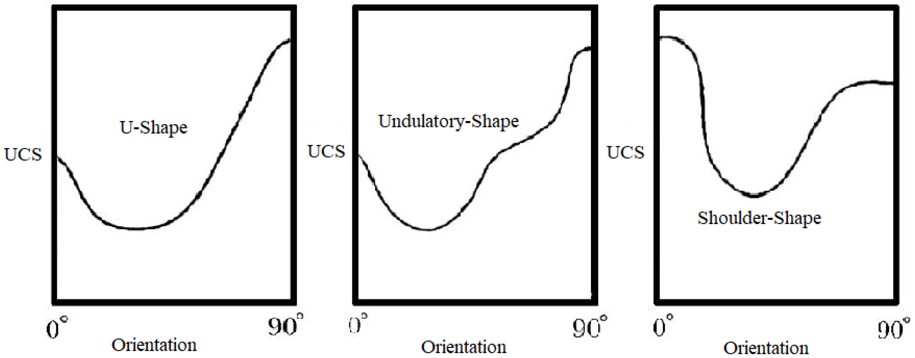
Figure 1. Strength variation curve with orientation angle modified after [16].
Geosciences 14 00253 g001
Figure 2. Variation in tensile strength with anisotropic index [35].
Geosciences 14 00253 g002
Figure 3. Strength variations in anisotropic foliated rocks including slate [26], phyllite [54], schist [47], and gneiss [55] with confining pressures. The Anisotropic Index (σz/σx45z) of rock types can be defined as the ratio of differential stresses (σz = σ1–σ3) measured in the z direction and x45z orientations (σx45z) [48]. The σx45z refers to the differential stress measured in a 45-degree inclined direction relative to the vertical (z) axis.
Geosciences 14 00253 g003
Figure 4. Cracks in the matrix of foliated rocks [58].
Geosciences 14 00253 g004
Figure 5. Stress–strain curve evaluating the rock behavior [58,62].
Geosciences 14 00253 g005
Figure 6. Damage characteristics of mica and granular minerals (a) slipping, (b) kinking, (c) fracturing, and (d) transgranular cracking [58].
Geosciences 14 00253 g006aGeosciences 14 00253 g006b
Figure 7. (a) Post-failure photographs illustrating the failure modes in foliated rocks at varying orientation angles. The rock cores of gneiss under compression tests show their plane of failure as indicated by the yellow lines [78]. (b) The disc samples of phyllite subjected to Brazilian tests show their failure surface. The green line signifies the direction of foliations [44].
Geosciences 14 00253 g007aGeosciences 14 00253 g007b
Figure 8. The illustrations (ac) show the failure modes simulated by DEM. Whereas illustrations (df) exhibit post-failure microcrack distribution [141].
Geosciences 14 00253 g008
Table 1. Classification of anisotropic rocks based on strength ratio.
Strength RatioAnisotropic ClassReference
1.1–2.0Weakly Anisotropic[8]
2.0–4.0Moderately Anisotropic
4.0–6.0Highly Anisotropic
>6.0Very Highly Anisotropic
1.1–2.0Fairly Anisotropic[35]
2.0–3.0Moderately Anisotropic
3.0–5.0Highly Anisotropic
>5.0Very Highly Anisotropic
Table 2. Description of the failure modes in foliated rocks at varying orientation angles.
Applied LoadRock TypeMode of FailureReference
Uniaxial CompressionSchistβ = 0° axial tensile splitting, 0° < β < 90° failure along foliation, and β = 90° shear failure[81]
Triaxial CompressionSlate, Phyllite, Schistβ = 0°–60° slip failure along foliations and β = 60°–90° shear failure cross-cutting the foliations[33]
Uniaxial CompressionSchistβ = 0° shear failure cross-cutting the foliations, β = 35° shear failure along foliations, and β = 45°–60° shear failure along and cross-cutting the foliations[90]
Uniaxial CompressionSchistβ = 0° axial tensile splitting, β = 45°–60° slip failure along foliations, and β = 90° shear failure cross-cutting the foliations[82]
Uniaxial CompressionGneissβ = 0°–30° splitting along foliations, β = ≥45° combined shear-tensile failure, and β = 60°–90° conjugate shear failure cross-cutting the foliations[78]
Uniaxial CompressionSlateβ = 0° tensile splitting along foliations and β = 90° shear failure cross-cutting the foliations[85]
Triaxial CompressionSlateβ = 0° double cone failure, 15° < β < 75° clean sliding along foliation, and β = 90° axial splitting[86]
Uniaxial CompressionPhylliteβ = 0°–30° tensile-split and shear-slip along foliations, β = 45°–60° dominant shear-slip failure, and β = 60°–90° shear failure cross-cutting the foliations[87]
Brazilian Tensile TestSchistβ = 90° central tensile failure, non-central tensile failure, combined central tensile failure with shear crack, and multiple central tensile cracks[81]
Brazilian Tensile TestPhylliteβ = 0°–30° central tensile failure, β = 30°–60° slip in foliations or slip in foliations combined with central crack, and at β = 60°–90° non-central tensile failure[44]
Table 3. Summary of major advancements in the formulation of failure criteria for anisotropic rocks.
Major Developments in Failure CriteriaReference
A criterion was proposed for anisotropic geological media based on the theory of plasticity.[92]
A simple strength criterion was put forward based on the scalar function and strength tensors.[93]
The yielding and failure criteria were developed for transversely isotropic-oriented materials using information from tensorial generators, independent, and mixed stresses.[94]
A criterion was proposed for compressed anisotropic rocks subjected to a multiaxial state of stress considering the Von Mises failure criterion for ductile materials.[95]
A failure criterion for compressed anisotropic rocks was formulated based on viscoplastic constitutive modeling. In this criterion, the failure function was dependent on the stress tensor invariants and mixed invariants.[96]
A criterion was presented that generates an anisotropic yield envelope based on the 9 material parameters. The nonlinear yield function varies with hydrostatic pressure and orientation angle alteration.[97]
A strength criterion was put forward to evaluate the anisotropy of transversely isotropic rocks under a multiaxial stress state. The direction of the failure plane was predicted using the Hoek-Brown failure criterion and critical plane method.[98]
A failure criterion was derived for anisotropic geomaterials under a multiaxial stress state using the density distribution function of internal defects and damage evaluation rules. Furthermore, the failure plane’s orientation was also estimated using a critical plane approach.[99]
A new criterion was proposed to predict the anisotropic strength of transversely isotropic rocks using the Matsuoka–Nakai criterion for isotropic materials and the Coulomb criterion.[100]
Table 4. Modeling parameters for grain and contact as described by Wang and Cai [114].
Grain CharacteristicsContact Characteristics
Grain density ρ (kg/m3)Contact normal stiffness Jkn (GPa/m)
Elastic modulus E (GPa)Contact shear stiffness Jks (GPa/m)
Poisson’s ratio υ Contact stiffness ratio Jkn/Jks
Compressive strength UCS (MPa)Contact compressive strength (MPa)
Tensile strength UTS (MPa)Contact tensile strength (MPa)
Peak shear strength Cp (MPa)Contact peak shear strength JCp (MPa)
Peak friction angle ϕ p (deg)Contact peak friction angle J ϕ p (deg)
Peak dilation angle ψ p (deg)-
Residual shear strength Cr (MPa)Contact residual shear strength JCr (MPa)
Residual friction angle ϕ r (deg)Contact residual friction angle J ϕ r (deg)
Residual dilation angle ψ r (deg)-
Plastic strain ε (%)-
Table 5. Summary of major advancements in the simulation of strength behavior of anisotropic foliated rocks.
DEM Simulation for Anisotropic RocksReference
A 3D DEM was presented to investigate the squeezing ground condition in mines. The effect of buckling, weak planes’ orientation, and fractures on rock mass was modeled using the DEM approach.[131]
Presented a systematically verified model for anisotropic rocks using bonded particle modeling (BPM) and smooth joint modeling (SJM). The model was extended from laboratory scale to field to solve upscaled engineering problems.[132]
The effect of weak layer orientations on strength, stiffness, and fracture pattern was simulated using smooth joint modeling (SJM).[133]
To evaluate the fracturing event in transversely isotropic rocks, the moment tensor was analyzed using acoustic emission (AE) based DEM. The AE agreed the deterioration of rock under deviatoric stress and DEM simulated the damage processes of rocks.[134]
Simulated the relationship between microscopic characteristics of foliations with the macroscopic mechanical behavior of rocks using bonded particle modeling (BPM) and embedded smooth joint modeling (SJM).[135]
A 3D bonded particle DEM with varying smooth joint contact ratios was used for the simulation of the elastic and strength behavior of anisotropic rocks.[136]
The influence of confinement and weak planes on both microscopic and macroscopic failure processes was simulated using 3D DEM. The behavior of rock matrix and weak planes was modeled by nonlinear bond contact and smooth joint contact approaches.[137]
A 3D DEM was proposed for anisotropic rocks using the flat joint model and smooth joint model to investigate the effect of weak planes’ orientation on tensile strength, fracture pattern, and stress distribution.[138]
Investigated the anisotropic behavior of foliated rocks using 3D printing technology and hybrid finite discrete element modeling (FDEM) approach. Angular variation in weak plane orientation considerably affects the mechanical behavior of layered rocks.He et al. 2020 [139]
Disclaimer/Publisher’s Note: The statements, opinions and data contained in all publications are solely those of the individual author(s) and contributor(s) and not of MDPI and/or the editor(s). MDPI and/or the editor(s) disclaim responsibility for any injury to people or property resulting from any ideas, methods, instructions or products referred to in the content.