Article

A Hyperelastic Bounding Surface Plasticity Model for Unsaturated Granular Soils

by
Mehdi Kadivar
1,
Kalehiwot Nega Manahiloh
2,* and
Victor N. Kaliakin
1
1
Department of Civil & Environmental Engineering, University of Delaware, Newark, DE 19716, USA
2
Civil Engineering Department, Liberty University, Lynchburg, VA 24515, USA
*
Author to whom correspondence should be addressed.
Geosciences 2024, 14(6), 148; https://doi.org/10.3390/geosciences14060148
Submission received: 31 March 2024 / Revised: 13 May 2024 / Accepted: 28 May 2024 / Published: 30 May 2024

Abstract

:
In this paper, a state-dependent, bounding surface plasticity model that simulates the behavior of unsaturated granular soils is presented. An unsaturated, soil mechanics-compatible elastoplastic response is adopted in which no part of the response occurs in a purely elastic fashion. To create an appropriate hydro-mechanical coupling, a newer generation stress framework, consisting of the Bishop-type effective stress and a second stress variable, is used in conjunction with a soil-water characteristic curve function. Details regarding the model development, parameter estimation, and assessment of the model’s predictive capabilities are outlined. With a single set of parameter values, the model realistically simulates the main features that characterize the shear and volumetric behavior of unsaturated granular soils over a wide range of matric suction, density, and net confining pressure.

1. Introduction

Environmental conditions such as precipitation, infiltration, and evaporation influence the location of the groundwater table and, therefore, the thickness of the unsaturated soil zone. In this zone, the soil is characterized by variations in moisture content and in the associated water pressure. Ignoring conditions in the tightly adsorbed water layer in the unsaturated zone, the pore-water pressure is negative. Depending on the type and permeability of the soil, the magnitude of the pore pressure can vary over six orders of magnitude. Reports indicate that, in the USA alone, problems associated with unsaturated soils (e.g., volume change, pressure generation, and moisture transport) annually inflict over $15 billion in damage to buildings, roads, and pipelines, e.g., [1].
Constitutive modeling of unsaturated soils has drawn attention since the 1990s. Research in this field was pioneered by the likes of Alonso, et al. [2], who extended the modified Cam-Clay model [3] to one based on the concept of two independent stress state variables. In this concept, the behavior of unsaturated soils is governed by matric suction and net stress [4,5]. Based on the concept of two stress state variables and using the extended critical state concept, several constitutive models were subsequently developed and used to simulate the behavior of unsaturated soils, e.g., [6,7,8,9,10]. However, Gens, et al. [11] postulated that the framework of two independent stress state variables is successful only in cases where one of these variables is kept constant. According to Nuth and Laloui [12], separating the mechanical stress from the hydraulic stress prevents the proper simulation of the hydro-mechanical coupling phenomena observed in unsaturated soils. Sheng [13] indicated that, in the two-stress state variable approach, a smooth transition between saturated and unsaturated states was missing. Using energy principles, Houlsby [14] rigorously demonstrated that two sets of stress–strain variables (e.g., the effective stress and matric suction as stress variables and the strain of the solid skeleton and degree of saturation as kinematic variables) are adequate to describe unsaturated soil behavior.
The Bishop-type [15] effective stress has been extensively used in describing unsaturated soil behavior, as evident in the works of [16,17,18,19,20,21,22,23,24,25,26,27,28,29,30]. The constitutive relationships presented in the aforementioned studies fall within the framework of standard rate-independent elastoplasticity. They predict path-dependent elastic response for stress states within a yield surface, which is counter to the framework of elastoplasticity. In such formulations, the elastic response should be path-independent. Additional details regarding these observations will be provided in the Strain Decomposition section of this paper.
The effective stress framework allows the direct incorporation of the soil water characteristic curve (SWCC) and the intrinsic coupling between the mechanical and hydraulic behavior. In addition, when the state of the soil changes to full saturation, the associated effective stress reduces to Terzaghi’s effective stress. This characteristic makes such a framework a viable choice for implementing a constitutive model for unsaturated soils into new or existing finite element or finite difference computer programs, as most of these are written in terms of effective stress for saturated soils. Consequently, a natural transition to unsaturated states can be realized by simply replacing Terzaghi’s effective stress with Bishop’s definition [12].
In elastoplastic models for unsaturated soils employing the effective stress framework, the yield surface can be made a function of the matric suction and/or the degree of saturation [19,24,26,31,32]. This gives such models the ability to correctly simulate the influence of unsaturated conditions on plastic straining, including the possible occurrence of collapse compression during wetting.
The concept of a bounding surface in stress space was independently introduced by Krieg [33] and Dafalias and Popov [34] to more accurately simulate the cyclic response of metals. The basic idea underlying bounding surface models is a smooth transition from elastic to plastic states. In such models, there is a yield surface whose size and location may vary within an outer or “bounding” surface. The plastic stiffness decreases as the material state approaches the bounding surface. This beneficial characteristic has led to the development of several bounding surface models for saturated soils [35,36,37,38,39,40].
Russell and Khalili [32] first applied the bounding surface concept to simulate the rate-independent behavior of unsaturated soils. They combined the framework of critical state soil mechanics with Bishop’s effective stress definition for such soils. Their model also accounted for possible particle crushing at high stresses. The capabilities of this model were assessed by simulating the axisymmetric triaxial response of both clean sand and pure clay.
By extending the bounding surface plasticity model of Bardet [36], which was originally developed for saturated sands, Morvan, et al. [41] proposed a bounding surface-based constitutive model for unsaturated soils. More recently, Patil, Hoyos, Morvan and Puppala [28] refined this model, taking into account the hysteretic behavior of a water retention curve and its dependence on the void ratio. A common trait of the aforementioned bounding surface constitutive models is that they all assume a hypoelastic response. However, as pointed out by Lashkari and Golchin [42], the lack of conservation of energy in hypoelasticity poses challenges in proving the accuracy of such models.
In the present work, a state-dependent, critical state-compatible constitutive model that accounts for the effect of matric suction on the hydro-mechanical response of unsaturated granular soils is described. The model is formulated in a rate-independent bounding surface plasticity framework and incorporates a newer generation of effective stress definition. The model represents an enhanced extension of the hyperelastic bounding surface model for fully saturated granular soils originally proposed by Lashkari, et al. [43]. In the unsaturated, soil mechanics-compatible elastoplastic response associated with the present model, no part of the response occurs in a purely elastic fashion. The elastic portion of the elastoplastic response is computed from a Gibbs free energy function suitable for unsaturated granular soil, thus satisfying the law of conservation of energy. Using a single set of parameter values, this model simulates the hydro-mechanical response of unsaturated granular soils with various ranges of density, normal stress, and matric suction. The model’s predictive capabilities are assessed by comparing its simulations with experimental data for clean sand, as reported by Russell and Khalili [32], and silty sand, as reported by Patil, Hoyos and Puppala [29]. The model is also compared with the bounding surface-based models of Russell and Khalili [32], Morvan, Wong and Branque [41], and Patil, Hoyos, Morvan and Puppala [28]. To rigorously assess the model’s performance, the statistical technique of Li and Zhu [44] is employed, wherein the normalized residual sum of squares (RSSmono) serves as the benchmark for comparison.
The authors deeply appreciate the importance of evaluating the model performance with varying stress paths, other test types, and plastic volumetric strains induced by wetting and drying cycles under isotropic loading conditions. However, due to page limit issues, the details pertaining to these issues must be deferred to future publications.

2. Model Development

The following sections present the development of the model. For simplicity, the model is formulated in axisymmetric triaxial space in terms of the mean normal effective stress (p’) and the deviator stress (q). Although implementing the model into general research and commercial computer programs would necessitate a more general, three-invariant framework, such development is beyond the scope of the present paper.

2.1. Effective Stress Definition

Following the principles of saturated soil mechanics, the effective stress vector (σ′) is written as follows:
σ = p q ,
where p’ and q are defined above. By adopting Bishop’s relationship, p is defined as follows:
p = p n e t + χ s ,
where p n e t = p t u a is the net confining stress, p t is the total confining stress, u a is the pore air pressure, s = u a u w is the matric suction, and u w is the pore water pressure. In this work, matric suction signifies the component of the total suction, excluding the osmotic fraction. In Equation (2), χ is Bishop’s effective stress parameter, which varies between a value of zero (corresponding to dry conditions) and one (corresponding to water-saturated conditions).
Several functional relationships have been proposed for χ, most of which relate it to the degree of saturation (Sr). Schefler [45] suggested that χ be equal to Sr. The use of this definition, in conjunction with experimental data for unsaturated soils with different values of matric suction, showed that a unique critical state line (CSL) was, however, not achieved in p’-q space. This observation is evident in Figure 1a, where it can be seen that for each value of matric suction (s), a different critical state line must be defined.
To avoid the need for defining multiple CSLs in p’-q space, Manzanal, Pastor and Merodo [24] suggested that the effective degree of saturation, Sre, be used in the definition of χ as follows:
χ = S r e = S r S r 0 1 S r 0 ,
where Sr is the current degree of saturation and Sr0 is the residual state degree of saturation, which can be estimated from the SWCC. The symbols ⟨ ⟩ represent Macaulay brackets; for some quantity x, they give x = x   if   x > 0   and   x = 0   if   x 0 . As evident from Figure 1b, Equation (3) eliminates the need for defining multiple CSLs in p’-q space.

2.2. The Idealization of the Soil Water Characteristic Curve (SWCC)

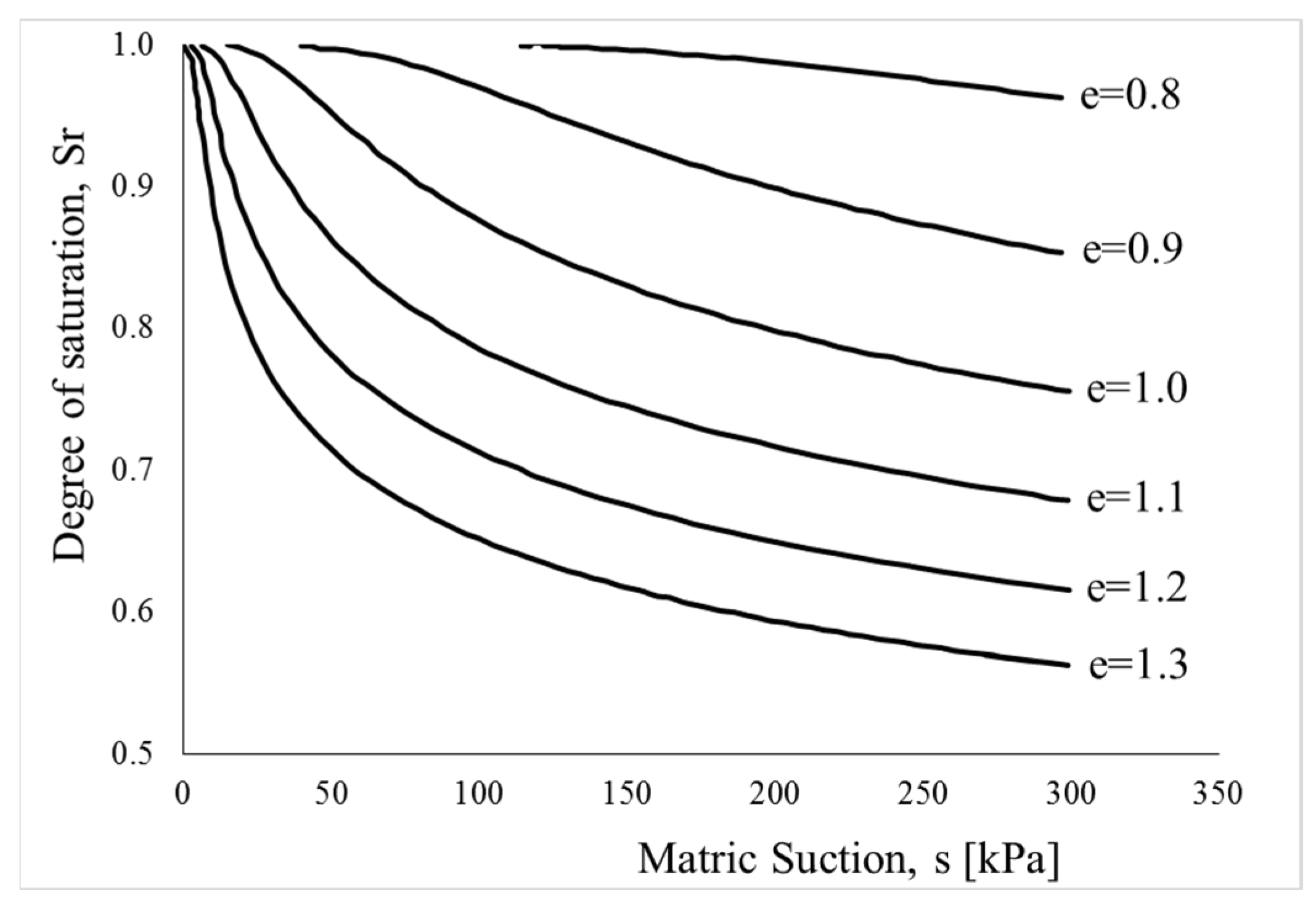
The constitutive relationship between matric suction and the water content (or degree of saturation) of soils is commonly described using the SWCC. A number of functional forms have been suggested for SWCCs, (e.g., [47,48,49,50,51,52,53,54]). The SWCC of a given soil varies depending on the direction and history of wetting considered. This variation in SWCCs is referred to as hysteresis [55]; its physical description was pioneered by Poulovassilis [56]. Past investigations have shown that the SWCC of natural soil differs from the SWCC of the same soil recompacted to the same density at the same water content [57,58]. Similar studies have reported that additional factors such as stress state, loading and wetting history, and soil structure affect the SWCC. In addition, many studies have investigated the dependence of the SWCC on a soil’s initial density, (e.g., [6,32,57,58,59,60,61,62,63]). For example, from Figure 2, it is evident that different SWCCs are obtained for different densities, as quantified by the void ratio (e).
Following the work of Wheeler [62] but adopting a simplified approach, Gallipoli, Wheeler and Karstunen [63] proposed a normalization technique that yields a unique SWCC for different values of density. In this technique, the degree of saturation is correlated with not only the matric suction but also the density (i.e., specific volume). Adopting such a technique, Manzanal, Pastor and Merodo [24] defined a modified suction (s*) that is a function of the void ratio according to the following:
s * = s e Ω ,
where Ω is a curve-fitting parameter.
In the present model, the relationship of Fredlund and Xing [47] for the SWCC is adopted and combined with the aforementioned normalization technique of Gallipoli, Wheeler and Karstunen [63]. The resulting normalized SWCC function thus takes the following form:
S r = S r 0 + 1 S r 0 1 ln 1 + s s 0 ln 1 + 10 6 s 0 ln exp 1 + s * a v . p r e f n v m v ,
In Equation (5), a v ,   n v ,   and   m v are model parameters, and S r 0   and   S 0 are the residual values of the degree of saturation and matric suction, respectively. The value of 106 corresponds to the suction of 1 GPa, which is the value at which the degree of saturation, S r , reaches the residual value, S r 0 , in the SWCC expression proposed by Fredlund and Xing [47].

2.3. Strain Decomposition

The strain vector ( ε ) that is work-conjugate to the effective stress vector given in Equation (1) is as follows:
ε = ε v ε q ,
where ε v and ε q are, respectively, the volumetric and distortional components of the strain vector.
Assuming infinitesimal displacements and displacement gradients, the total strain rate vector is additively decomposed into an elastic and plastic part as follows:
ε ˙ = ε ˙ v ε ˙ q = ε ˙ e + ε ˙ p = ε ˙ v ε ˙ q e + ε ˙ v ε ˙ q p ,
where the superscripts e and p denote the elastic and plastic parts, respectively, of ε . A superposed dot indicates a material time derivative or rate, which is used here in lieu of incremental notation as a convenience since the formulation is rate-independent.
Within a conventional elastoplasticity framework, the response associated with stress states within the elastic region is, by definition, independent of the stress path. However, Zhang and Lytton [64] and Sheng, et al. [65] showed that for unsaturated soils, the “elastic” volumetric change is stress-path dependent. As Figure 3 illustrates, a closed loop of net stress and suction changes within the elastic region does not necessarily lead to a closed loop of effective mean stress changes. This is because of the material state dependency of the effective stress [13]. The lack of a closed-loop means that, even for seemingly elastic stress states, the response is stress-path dependent. A model that exhibits stress-path-dependent elastic behavior is inconsistent with classical elastoplasticity theory and thermodynamic considerations.
According to Collins and Houlsby [66], for materials in which elastic parameters are dependent on internal parameters due to elastic-plastic coupling, the traditional elastic-plastic strain decomposition is not valid. Following the work of Maier and Hueckel [67], Collins and Houlsby [66] postulated that instead of using “elastic” and “plastic”, the terms “reversible” and “irreversible” should instead be used when describing strain rates. In their definition, the elastic strain was assumed to be affected by the plastic strain; coupled elastic-plastic strain rates were thus added to the elastic strain rates. Collins and Houlsby [66] thus decomposed the elastic strain rate into reversible and irreversible (coupled) portions. Table 1 summarizes their strain decomposition. In this table, the superscripts “r” and “i” denote the reversible and irreversible parts, respectively, of the infinitesimal strain vector.
In the present model, due to the aforementioned path dependence of the elastic strains in unsaturated soils (Figure 3), it is assumed that no purely elastic strains can develop at any time; the elastic strain is thus inherently coupled with the plastic strain. In light of the above discussion, the term “irreversible elastic strain vector” is adopted for the elastic strain that is coupled with the plastic strain.

2.4. Definition of the Elastic Response

The constitutive relation used by Golchin and Lashkari [68] and Alipour and Lashkari [69] is likewise adopted herein, i.e.:
p ˙ q ˙ = K J J 3 G ε ˙ v ε ˙ q e r ,
where K, G, and J are the hyperelastic moduli, which are non-linear functions of p’. Following the approach of Golchin and Lashkari [68], expressions for these moduli are calculated by partial differentiation of the Gibbs free energy function proposed by Einav and Puzrin [70], which guarantees the conservation of energy in any arbitrary closed loop. As derived by Golchin and Lashkari [68], this function is as follows:
Γ p , q , Χ = p 2 Χ 2 Χ p p 0 1 Χ K 0 F e 2 Χ 1 Χ p r e f 1 Χ + q 2 6 G 0 F e p X p r e f 1 Χ q 0 2 q p 0 Χ q 0 p 6 G 0 F e p 0 1 + Χ p r e f 1 Χ ,
where K o and G o are model parameters, P r e f is a reference pressure that is normally assumed to be equal to the atmosphere pressure P a t m = 101   kPa ,   p 0   and   q 0 are the values of p’ and q at zero elastic strain, respectively, and F(e) is a function of the void ratio (e) and particle shape. Lashkari, Karimi, Fakharian and Kaviani-Hamedani [43] proposed the following expression for granular soils with angular particles:
F e = 2.97 e 2 1 + e ,
The comparable expression for granular soils with well-rounded particles is as follows:
F e = 2.17 e 2 1 + e ,
In Equation (9), the elastic variable X, which evolves with plastic hardening, is defined as follows:
X = X η = X m i n + X m a x X m i n 1 + B M η e x p n b ψ 1 ,
where values of X m a x   = 0.95, X m i n = 0.50, and B = 0.10 are adopted from Lashkari, Karimi, Fakharian and Kaviani-Hamedani [43]. In Equation (12), M is the slope of the CSL in p’-q space that takes on values of Mc and Me for axisymmetric triaxial compression and extension, respectively. The quantity η = q/p’ is the stress ratio, nb is a model parameter (to be discussed in the next section), and ψ is the Been and Jefferies state parameter [71] that represents the state dependency of the proposed model by relating a given state of soil with its critical state according to the following:
ψ = e e c ,
where ec is the value of the void ratio (e) at critical state for the current value of p’.
As mentioned above, the moduli K, G, and J appearing in Equation (8) are obtained by suitable partial differentiation of the Gibbs free energy function, giving the following
K = 1 1 X X 1 6 . K 0 G 0 . η 2 K 0 p r e f F e p p r e f X ,
G = 1 1 X X 1 6 K 0 G 0 η 2 G 0 F e + X X + 1 6 K 0 F e η 2 p r e f p p r e f X ,
J = 1 1 X X 1 6 . K 0 G 0 . η 2 Χ η K 0 p r e f F e p p r e f X = Χ η K ,
For the special case of isotropic loading, η = 0. The above moduli then reduce to the following functional forms, originally proposed by Hardin and Richart [72]:
K = K 0 p r e f   F e p p r e f X ,
G = G 0 p r e f   F e p p r e f X ,
J = 0 ,

2.5. Definition of the Bounding Surface

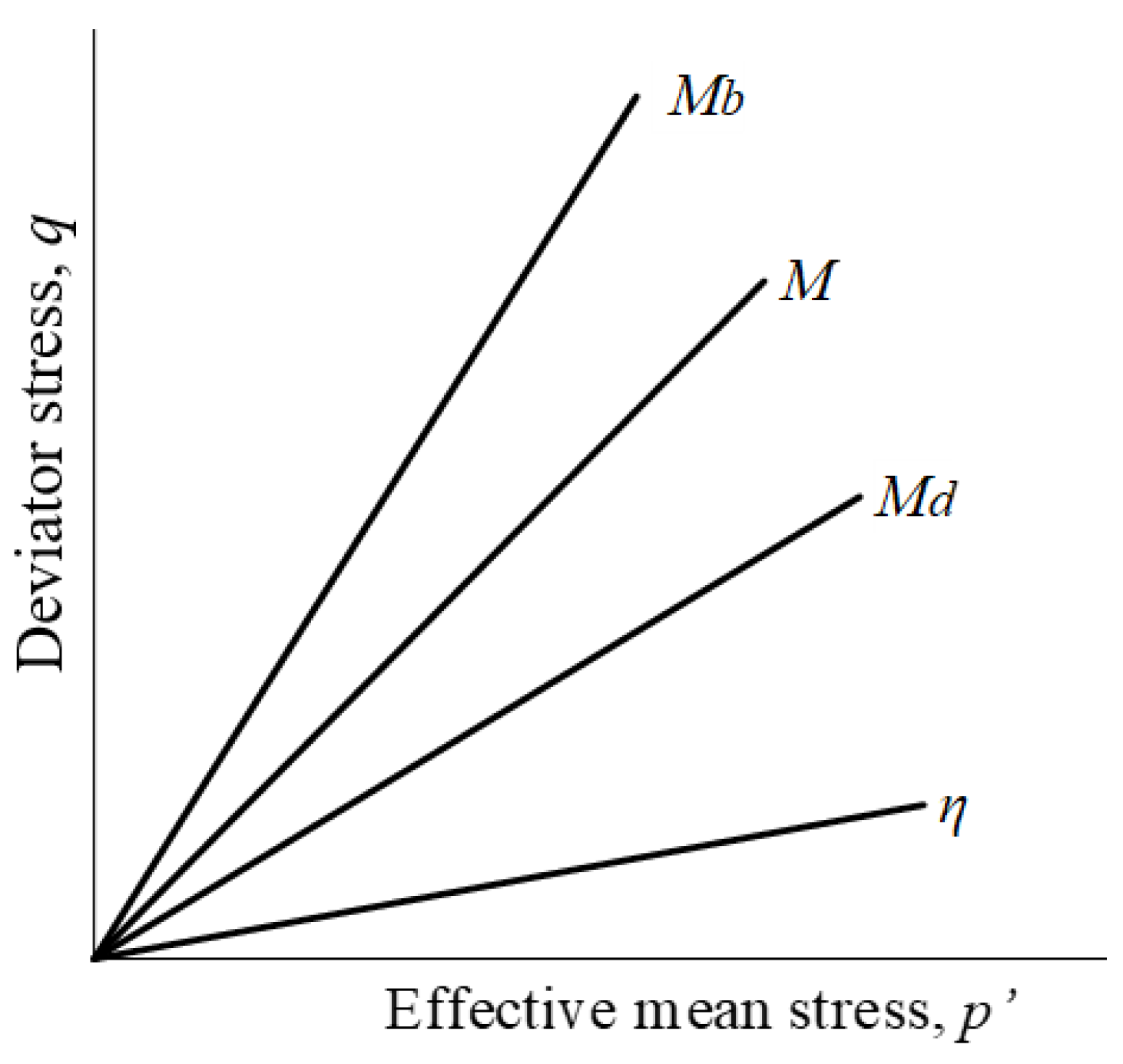
In p’-q space, the bounding surface is represented by a straight line with the slope of Mb (see Figure 4). Mb is related to the slope of the CSL, M, according to the following:
M b = M   e x p n b ψ ,
where nb is a model parameter by which the peak shear stress is simulated (also see Equation (12)).

2.6. Definition of the Dilatancy Surface

Similar to the bounding surface, the dilatancy surface is defined as a straight line in p’-q space with a slope of Md (Figure 4). Md is also a function of the slope of the CSL according to the following:
M d = M   e x p n d ψ ,
where nd is a model parameter by which the volume phase transformation is simulated.

2.7. Definition of the Critical State Void Ratio

Li and Wang [73], Lashkari and Yaghtin [74], and Lashkari, Karimi, Fakharian and Kaviani-Hamedani [43] used the following relationship to define critical state void ratio for fully saturated soils:
e c = e 0 λ p p r e f ζ ,
where e0, λ, and ζ are model parameters and pref is as previously defined. One important attribute of Equation (22) is that, for fully saturated granular soils with various initial densities and stress states, it yields a unique CSL in the space of e versus p p r e f ζ .
For unsaturated states, critical state experimental data in this space are, however, dependent on the values of matric suction. Consequently, as shown in Figure 5a, a unique line cannot fit all of the experimental data [10]. Indeed, different CSLs need to be defined in this space for different levels of matric suction.
Gallipoli, et al. [75] proposed a normalization approach that brings critical state data with different values of matric suction into a unique line. Their approach, which is adopted in the present model, consists of the following normalization, which relates the critical state effective stress for saturated conditions to its value for unsaturated conditions according to the following:
p n c s u n s a t p n c s s a t = 1 + g ξ ,
where p n c s s a t and p n c s u n s a t are the critical state effective confining pressures at saturated and unsaturated conditions, respectively.
In Equation (23), the function g ξ is given by the following:
g ξ = a . exp b . ξ 1 ,
where a and b are model parameters and ξ is a “cementation” parameter. The latter is defined by the following relationship [75]:
ξ = f s . 1 S r ,
where Sr is again the degree of saturation. The term (1 − Sr) takes into account the number of water menisci per unit volume of the soil. The suction-dependent function f s represents the magnitude of the inter-particle contact force due to the matric suction.
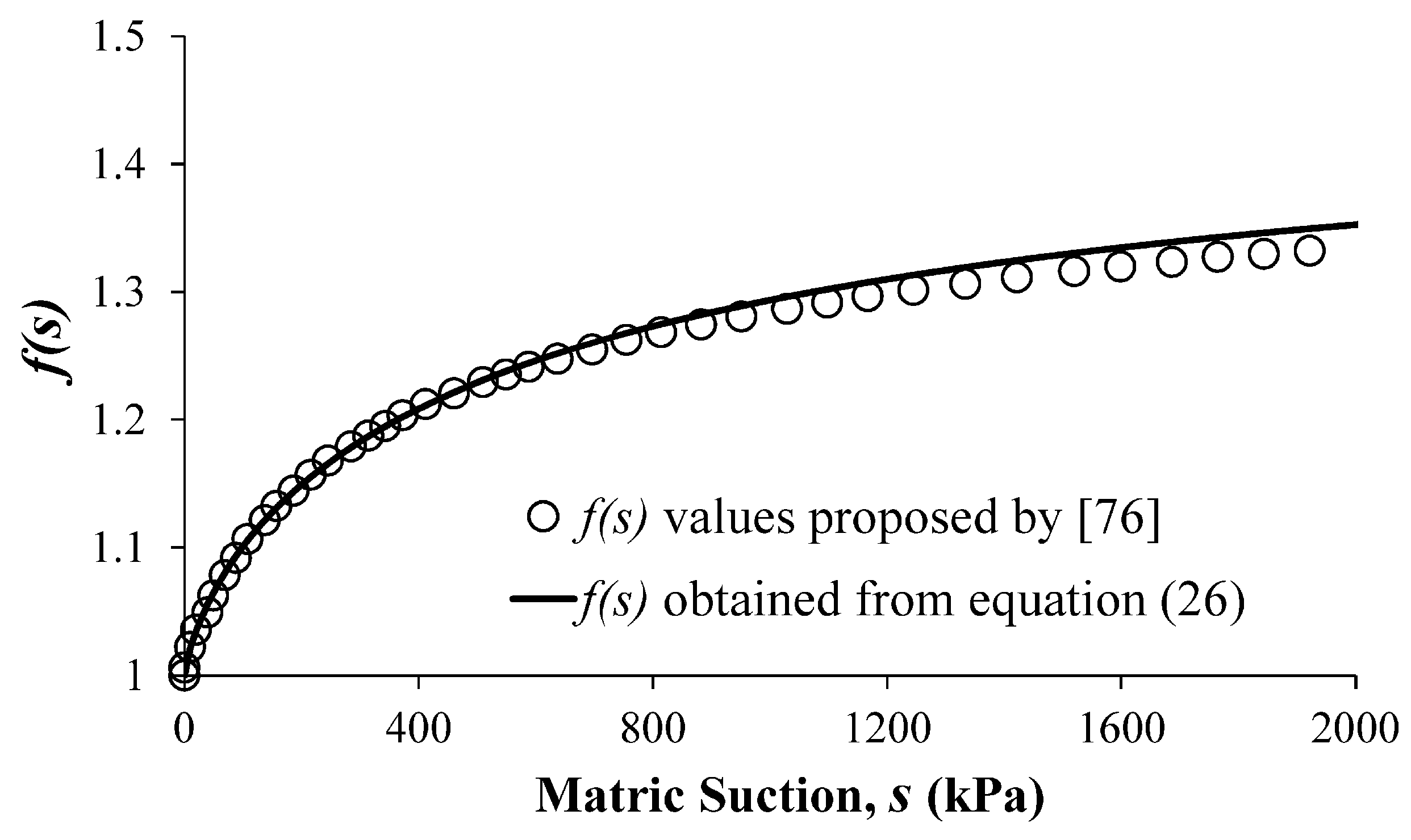
Referring to the theoretical expression derived by Fisher [76], the maximum value for f s is 1.5 (for infinite suction), while its minimum value is 1.0 (for zero suction). In the present model, the following relationship, proposed by Lashkari and Kadivar [77], is used for f s :
f s = 1 + s 0.75 2 125 + s 0.75 ,
Figure 6 shows the variation of f s with suction s.
Recalling that Equation (22) applies for fully saturated conditions, in light of Equation (23), this expression is modified for unsaturated granular soils, giving the following:
e c = e 0 λ p p r e f 1 + g ξ ζ ,
where, e 0 , λ , and ζ are again model parameters. Unlike Equation (22), Equation (27) provides a unique CSL in e p p r e f 1 + g ξ ζ space for unsaturated soils at different initial conditions. Figure 5b illustrates the normalization effect of Equation (27). It is evident that this normalization transforms the scattered experimental data shown in Figure 5a more nearly into a unique line.

2.8. Definition of the Flow Rule, Hardening Rule, and Dilatancy Function

The plastic shear strain rate is obtained using the non-associative flow rule of Dafalias and Manzari [39], which is written as follows:
ε ˙ q p = Λ η ˙ K p ,
where Λ is a scalar loading index, η is again the stress ratio, and K p is the dimensionless plastic-hardening modulus given by the following:
K p = h 0 1 c h e M b η 1 p r e f p 1 Χ ,
where h 0 and c h are dimensionless model parameters, M b is given by Equation (20), and Χ is the elastic variable defined in Equation (12).
The total irreversible strain vector is then calculated from the following equation:
ε v ε q i = ε v ε q e i + ε v ε q p = Γ , p Χ Χ , η K p ε ˙ q p + ε ˙ v p Γ , q Χ Χ , η K p + 1 ε ˙ q p ,
where Γ , p Χ = 2 Γ p Χ , Γ , q Χ = 2 Γ q Χ , and Χ , η = Χ η , with Γ being the Gibbs free energy function given by Equation (9).
For isotropic loading (J = 0), by imposing the consistency condition and combining it with Equations (8) and (30), the scalar loading index is calculated from the following equation:
Λ = 3 G ε ˙ q K η ε ˙ v p K p + 1 + Γ , q Χ Χ , η K p 3 G K η d ,
which has the form of the loading index originally given by Dafalias and Manzari [39]. In Equation (31), d is the following dilatancy function:
d = A d 2 M d η 1 + c M M d η ,
In Equation (32), A d is a model parameter, and c = M e / M c , where Mc and Me are again the slopes of critical state lines in axisymmetric triaxial compression and extension, respectively [39]. According to Lashkari, Karimi, Fakharian and Kaviani-Hamedani [43], for practical problems, a value of c = 0.7 provides reasonable results. As such, this value is adopted in this work. Knowing that d = ε ˙ v i ε ˙ q i and considering Equation (30), the plastic volumetric strain rate is given by the following:
ε ˙ v p = d Γ , q χ Γ , p χ χ , η K p + d ε ˙ q p ,

3. Determination of Model Parameters

Associated with the most general form of the present model are 14 parameters (K0, G0, e0, λ, a, b, ζ, Mc, Me, nb, nd, Ad, h0, and ch) whose values must be determined for a particular soil. There are also four parameters with default values of pref = 101 kPa, Xmax = 0.95, Xmin = 0.50, and B = 0.10 that can be used for all soils. Six additional parameters (av, Ω, nv, mv, Sr0, and s0) characterize the SWCC function that was adopted in the present model (recall Equations (4) and (5)). The values of these six parameters are obtained by regression-based curve fitting of the SWCC experimental data for a particular soil.
The following sections describe how values for the aforementioned 14 model parameters are determined from experimental data.

3.1. Elastic Parameters

The parameters K0 and G0 enter the formulation through the Gibbs free energy function given by Equation (9). They are used in the definition of the elastic moduli K, G, and J as given by Equations (14)–(19). A value for the parameter K0 can be determined from an isotropic compression test in which p’ increases but q = 0, thus rendering J = 0 from Equation (16). From this test, the bulk modulus K is equal to the slope of the line tangent to the initial portion of the mean effective stress (p’) versus volumetric strain curve, from which K0 can be determined by employing Equation (17). The parameter G0 is best determined from a test in which q is increased from zero at constant p’. Since the test starts at q = 0, η is small initially, thus rendering small values of J from Equation (16). From this test, the value of G is determined from the initial slope of the curve of deviator stress versus distortional strain. In such a test, the value of G0 is approximately equal to 3G. Values of K0 and G0 can also be determined from the results of resonant column or bender element tests [42].

3.2. Critical State Related Parameters

The seven parameters e0, λ, a, b, ζ, Mc, and Me are associated with the definition of the critical state. Values of e0, λ, a, b, and ζ are determined by fitting a straight line to data plotted in e p p r e f 1 + g ξ ζ space. The parameters a, b, and ζ are then obtained using Equations (23)–(27). Values of e0 and λ correspond to the slope and intercept, respectively, of the aforementioned straight line. Finally, the values of Mc and Me correspond to the slopes of the CSLs that best fit the ultimate states of undrained stress paths, plotted in p’-q space, for axisymmetric triaxial compression and extension tests, respectively.

3.3. Parameters Controlling State-Dependency

The parameters nb and nd control the state dependency. At peak shear stress, the state of the soil is on the bounding surface. Here the stress ratio (η) is equal to Mb. Using Equation (20), nb is computed as follows:
n b = 1 / ψ ln ( M b / M )
At the point of phase transformation from compressive to dilatational response, the stress point lies on the dilatancy surface, where the dilatancy function given by Equation (32) is zero.
Using Equation (21), nd is computed as follows:
n d = 1 / ψ ln M d / M

3.4. Dilatancy Parameter

The dilatancy function, d, is obtained by dividing the irreversible volumetric strain increment by the irreversible distortional strain increment. Following Li and Dafalias [38], it is assumed that the irreversible strain increments are approximately equal to the total strain increments. Therefore d = ε ˙ v i ε ˙ q i ε ˙ v ε ˙ q , which can be obtained from the results of drained axisymmetric triaxial compression tests [68]. With d, Md, and h known, the value of Ad is then computed from Equation (32), giving the following:
A d = d 2 M d η 1 + c M M d η

3.5. Hardening Parameters

Finally, suitable values of the parameters h0 and ch, which enter the formulation through Equation (29), are determined by fitting model simulations to deviator stress versus distortional strain data from axisymmetric triaxial tests.

4. Assessment of Predictive Capabilities

The predictive capabilities of the model are next assessed by comparing its simulations with two sets of axisymmetric triaxial test results. Included in these comparisons are simulations obtained using three other bounding surface plasticity models that were previously developed for unsaturated soils.

4.1. Simulation of the Behavior of Clean Sand

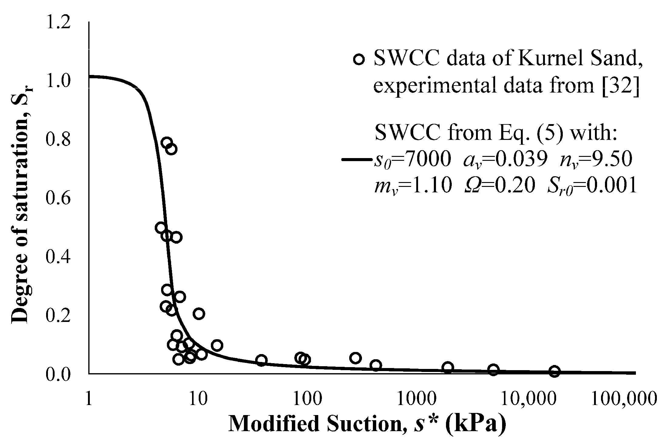
Russell and Khalili [32] performed suction-controlled axisymmetric triaxial compression tests on Kurnel sand, which is clean with no fines. For this sand, the specific gravity of the soil particles (Gs) is 2.65, the mean grain size (D50) is 0.31 mm, the uniformity coefficient (Cu) is 1.83, and the minimum and maximum void ratios are 0.60 and 0.92, respectively. Experimental data for the SWCC, along with the best-fit curve given by Equation (5), are presented in Figure 7. CSLs in the space of q-p’ and e p p r e f 1 + g ξ ζ are shown in Figure 8a,b, respectively. The complete set of model parameter values used in simulating the behavior of Kurnel sand is presented in Table 2.
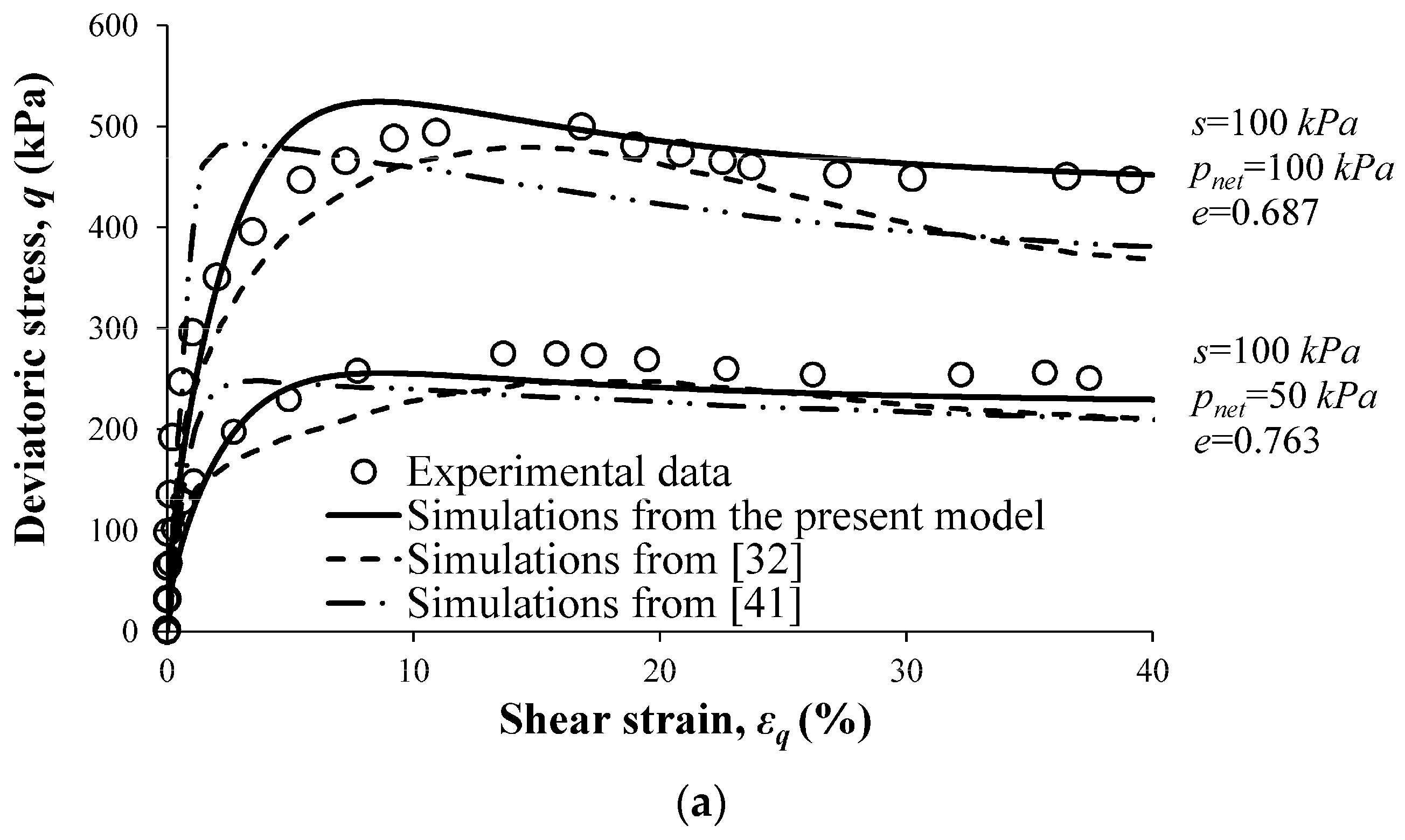
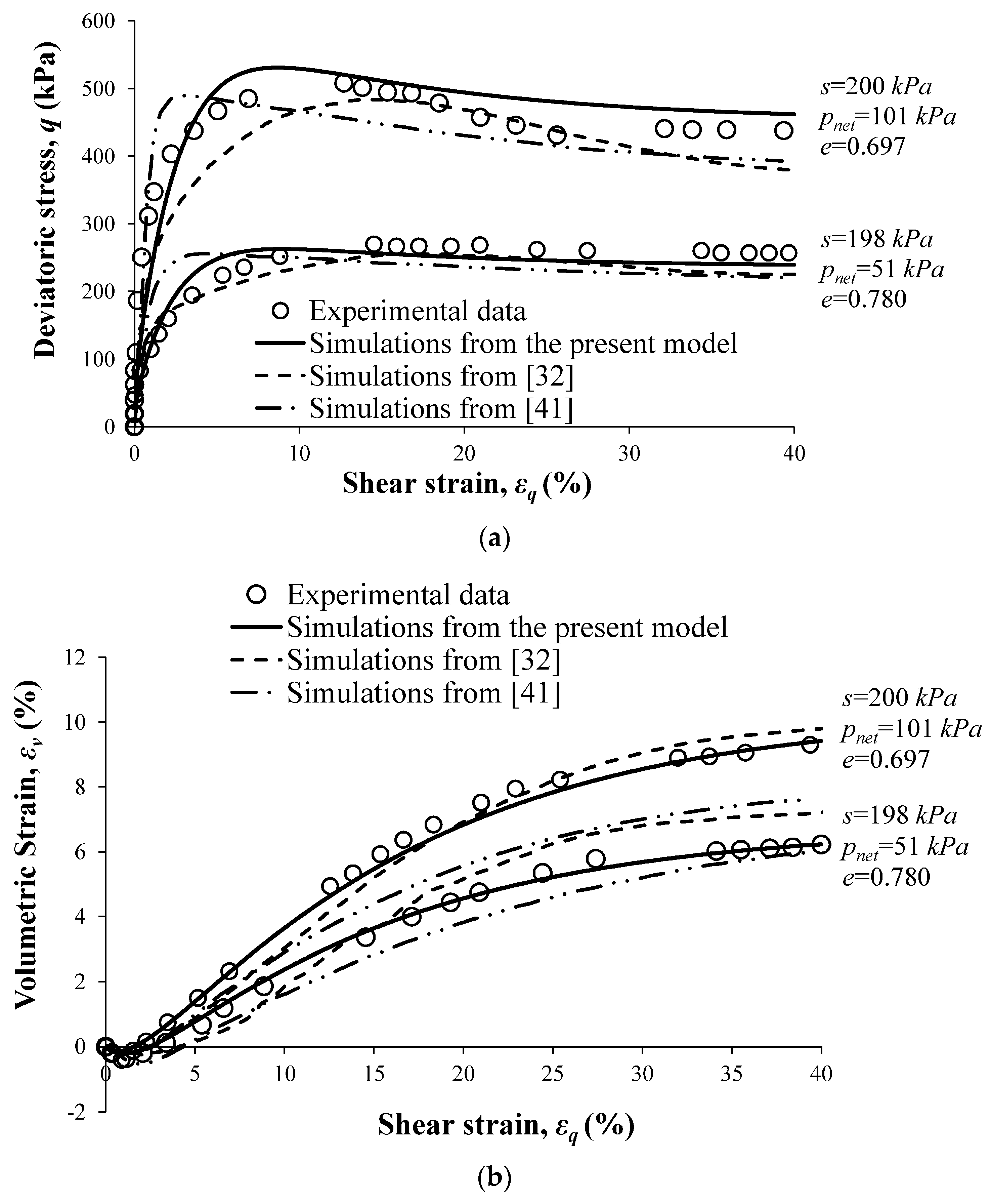
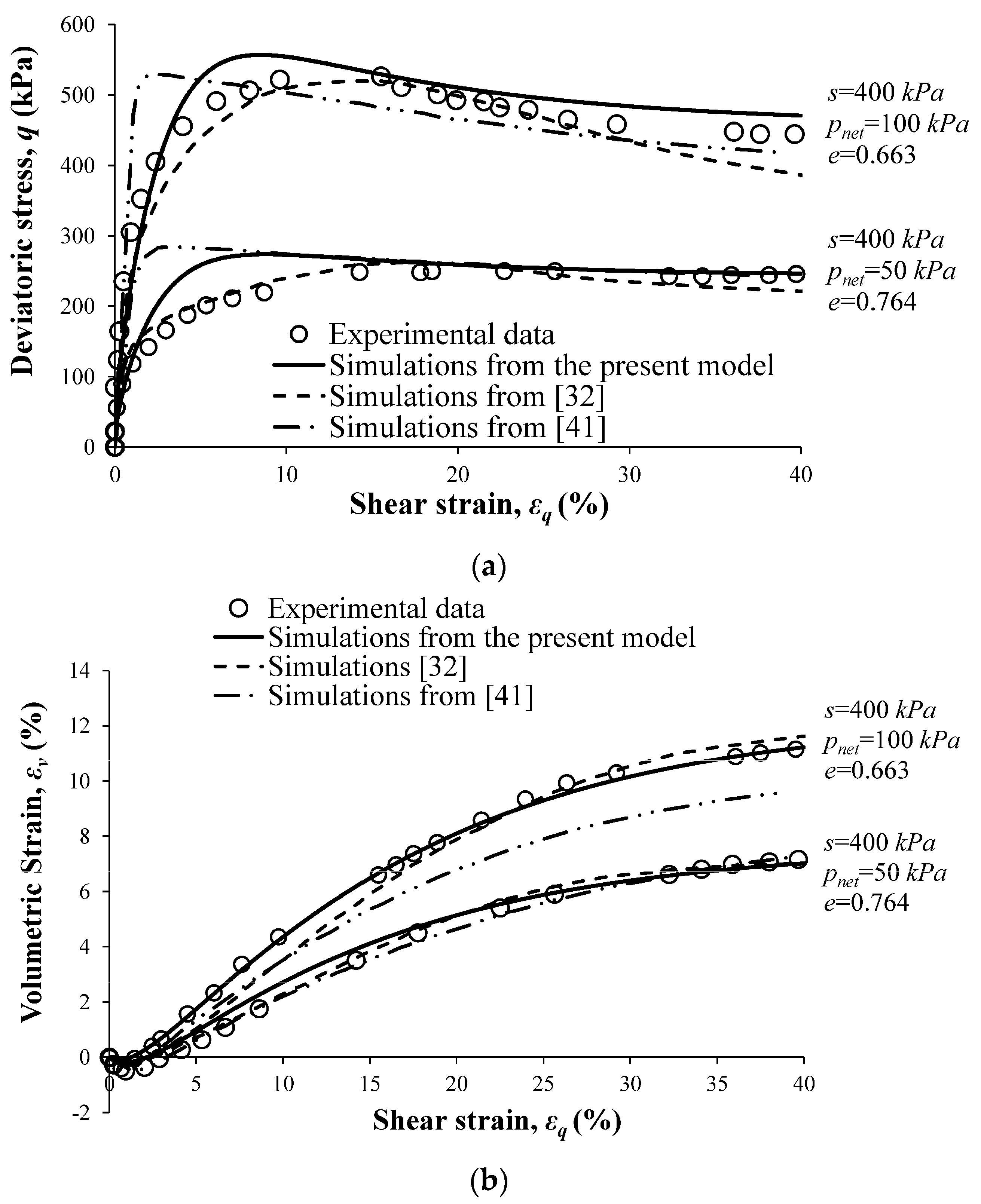
Figure 9, Figure 10, Figure 11 and Figure 12 compare the model simulations with experimental data and with the simulations obtained using the bounding surface models of Russell and Khalili [32] and Morvan, Wong and Branque [41]. The matric suction was maintained constant in these tests. Associated with the results shown in Figure 9, Figure 10, Figure 11 and Figure 12 were suctions of 51, 100, and 200 kPa, respectively. In these tests, the radial net stress varied from approximately 50 to approximately 100 kPa, and the initial void ratio varied between 0.658 and 0.780.
From Figure 9, Figure 10, Figure 11 and Figure 12, it is evident that the present model accurately simulates the experimental deviator stress versus distortional strain and volumetric strain versus distortional strain results. Comparing these simulations to those obtained using the bounding surface models of [32,41], it is evident that they are in better agreement with the experimental results. In particular, simulations from the model of Morvan, Wong and Branque [41] give a “stiffer” stress–strain response. This model is also unable to reproduce the critical state data, in terms of either volumetric strain or shear strength, especially at the higher radial net stress of 100 kPa. The model of Russell and Khalili [32], on the other hand, simulates a “softer” behavior as compared to the experimental data. Compared to the present model, it is less accurate at critical state. In addition, for the radial net stress of 50 kPa, the model predicted the peak deviatoric stress more accurately than the other two models. However, at the higher radial net stress of approximately 100 kPa, the Russell and Khalili [32] model provides a somewhat more accurate simulation.

4.2. Simulation of the Behavior of a Silty Sand

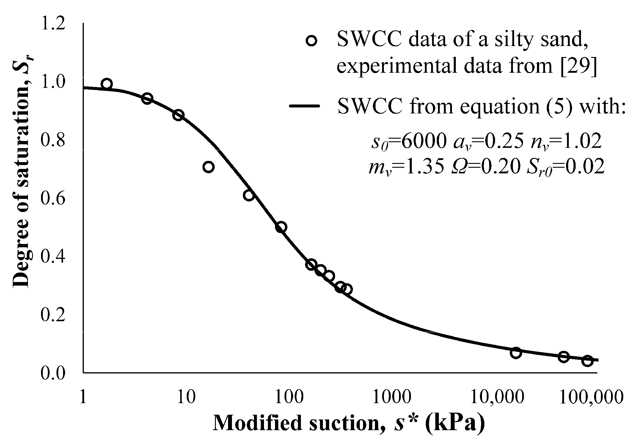
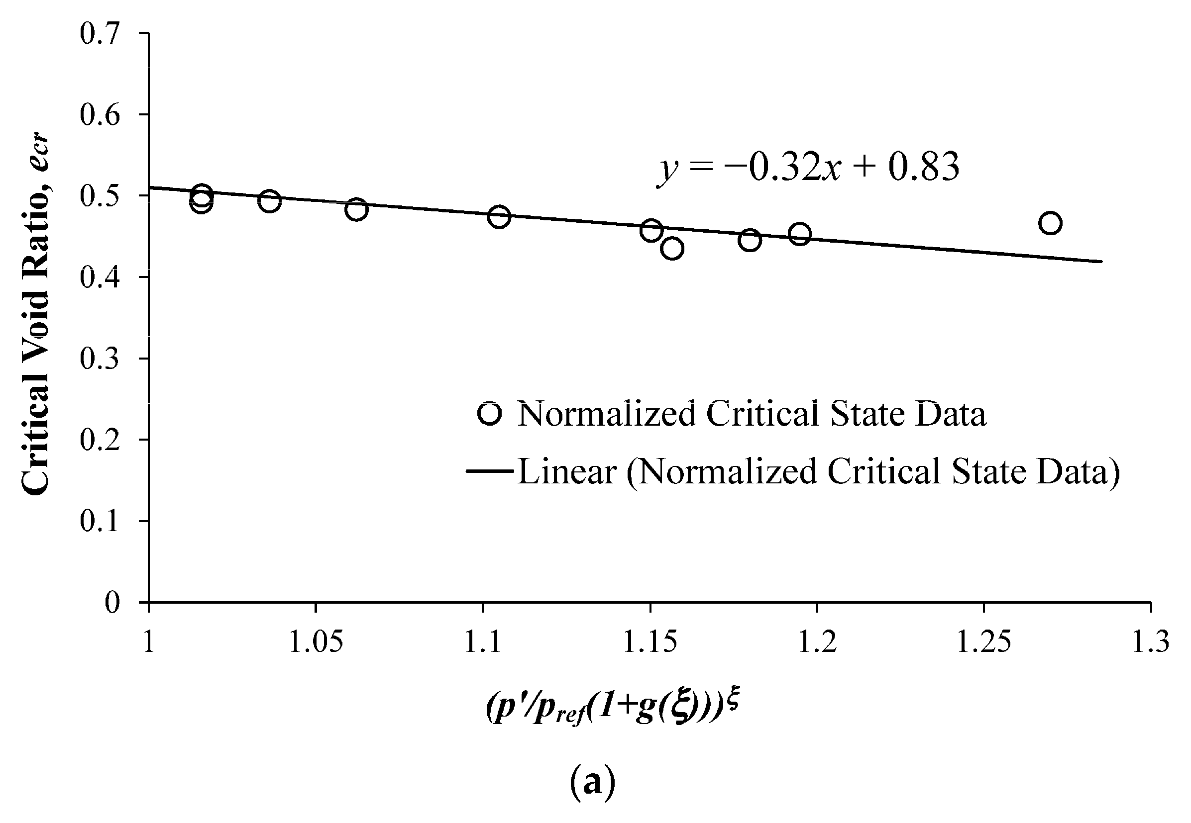
The present model is next used to simulate the axisymmetric triaxial behavior of silty sand. The experimental data for this soil have been reported by Patil et al. [29]. The soil consists of 55% sand, 37% silt, and 8% non-plastic clay-size fraction. For this soil, Gs is 2.67. The maximum dry density and optimum water content of the soil are 1.87 g/cm3 and 12.2%, respectively. Experimental data for the SWCC, along with the best-fit curve given by Equation (5), are presented in Figure 13. Critical state lines in q-p’ and e p / p r e f ( 1 + g ( ξ ) ) ζ spaces are shown in Figure 14a,b, respectively. The complete set of model parameter values used in simulating the behavior of the silty sand is presented in Table 3.
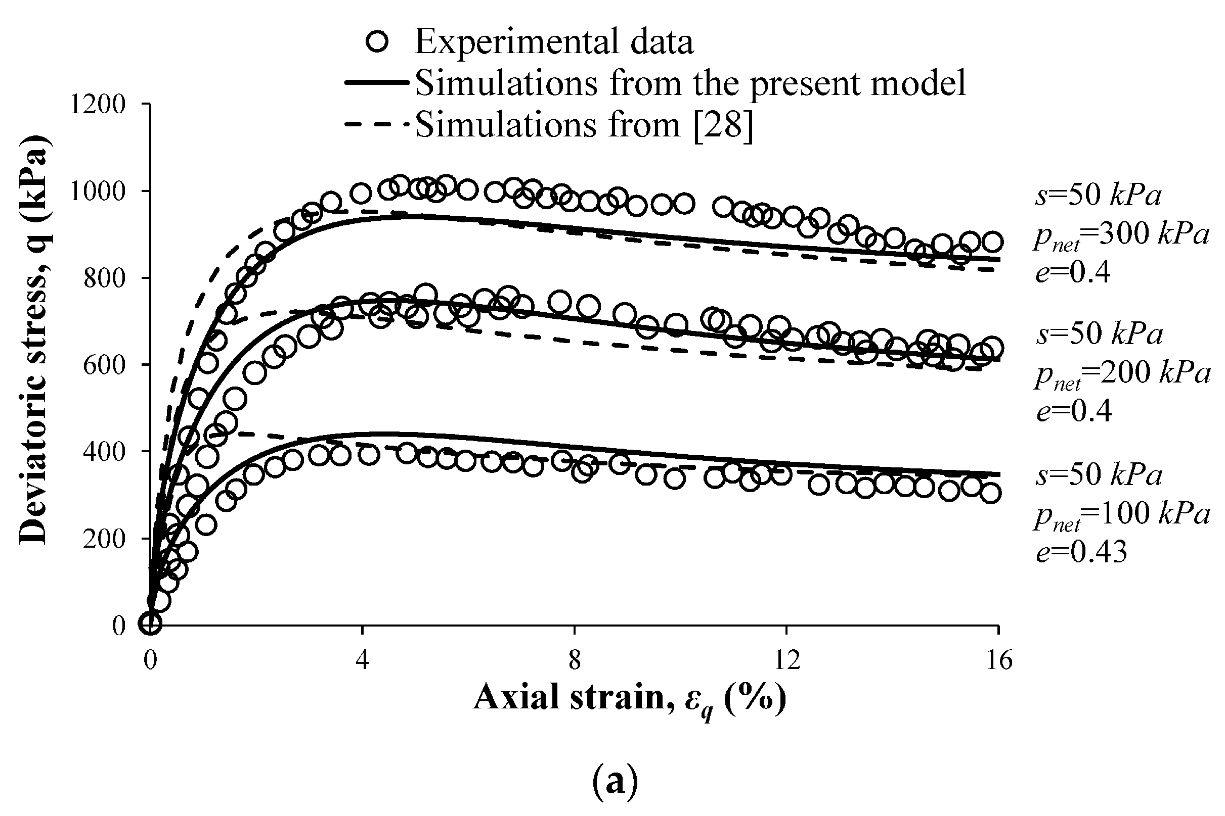
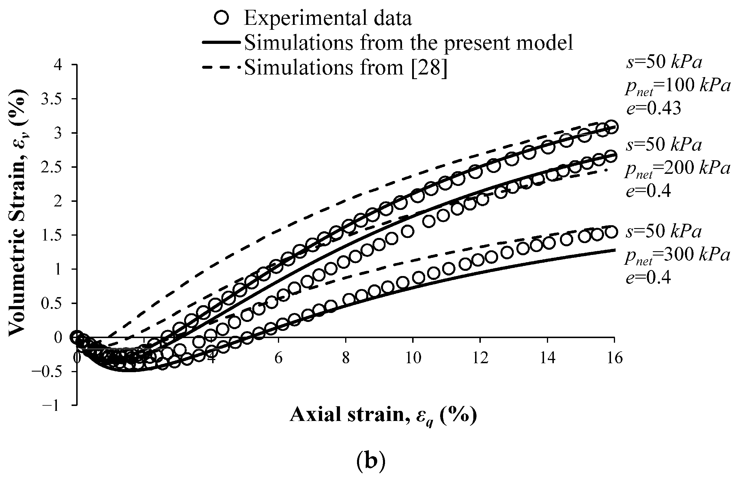
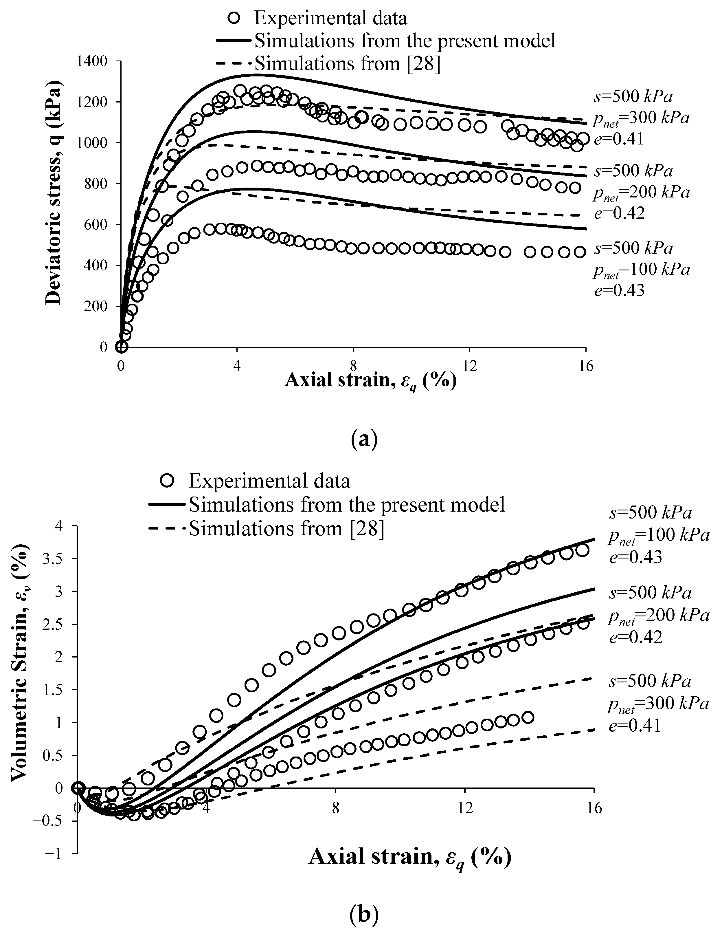
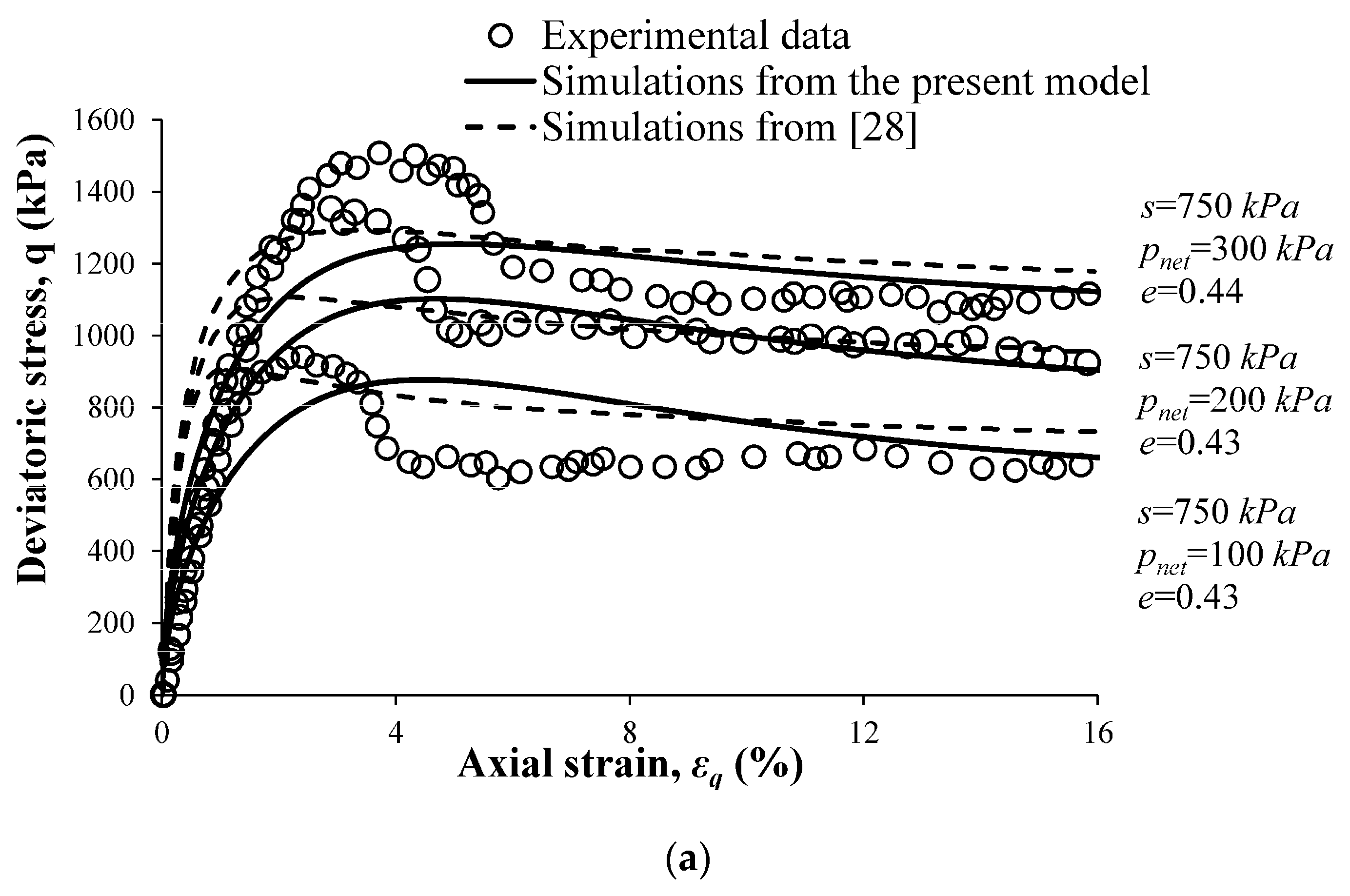
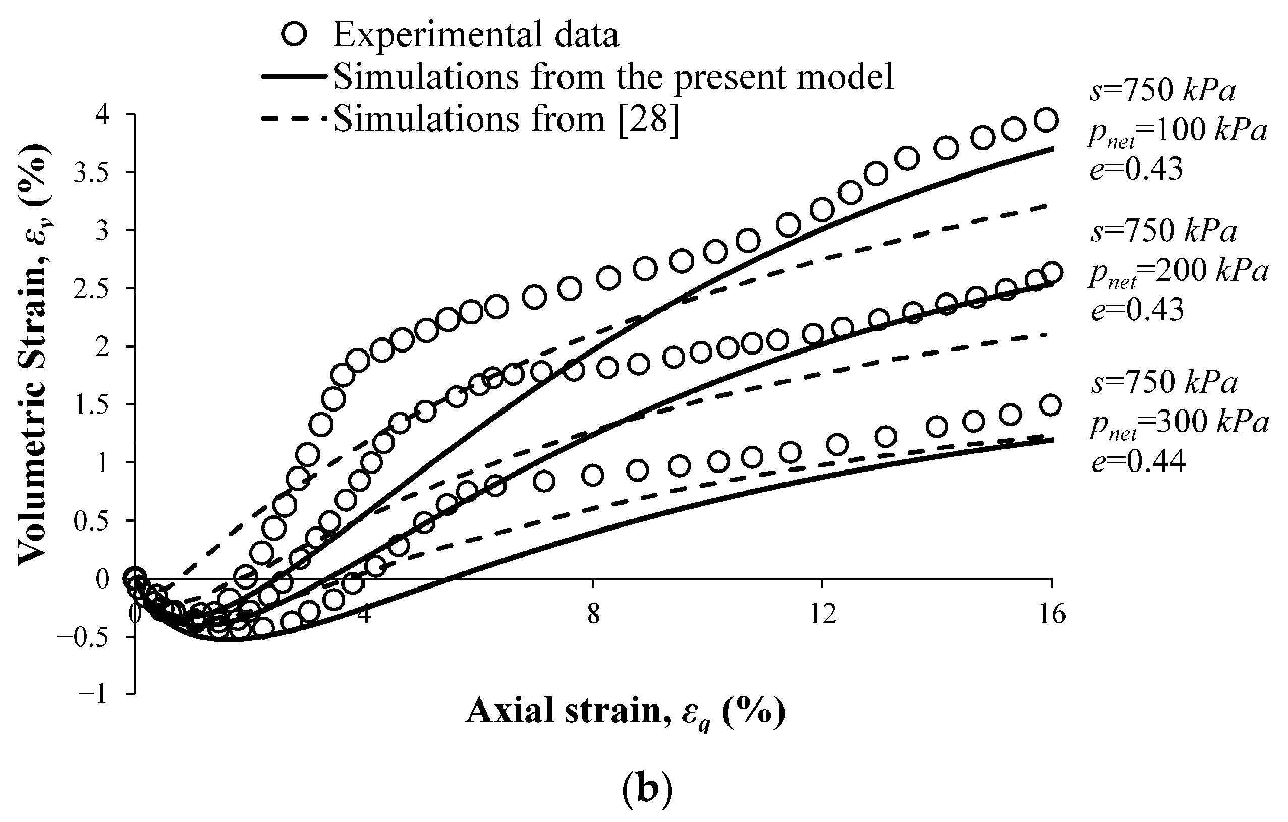
The triaxial compression tests were performed at four different suction values (50, 250, 500, and 750 kPa) and three different values of radial net stress (100, 200, and 300 kPa). In Figure 15, Figure 16, Figure 17 and Figure 18, the simulations obtained using the present model are compared with experimental data and with the simulations reported by Patil et al. [28]. Values of suction, radial net stress, and initial void ratio for each test are indicated on these figures.
The data of Patil et al. [29] provided in Figure 15, Figure 16 and Figure 17 shows that the post-peak softening increases with the increasing amount of suction. In particular, the tests at the highest suction value of 750 kPa (Figure 18) show apparent anomalies in the experimental deviator stress and volumetric behavior. The post-peak softening for this test has led to strain localization (i.e., the formation of a shear band). The displayed behavior precludes the simulation of all features of the behavior using any existing model for unsaturated soils. However, to be consistent, the results of the present model are presented for all the data. It can be observed that the present model is able to simulate the trend of the deviator stress and volumetric behavior shown in Figure 15, Figure 16 and Figure 17. Compared to the bounding surface model of Patil et al. [28], the present model yields better agreement with the experimental data. In particular, the model of Patil et al. [28] predicts a stiffer initial deviator stress–axial strain response, while the present model is smooth and close to the experimental data. Also, at the critical state, the present model shows a better overall agreement with the experimental data.

5. Conclusions

A state-dependent, critical state-compatible constitutive model that accounts for the effect of matric suction on the hydro-mechanical response of unsaturated granular soils was presented in this paper. The model is formulated in a rate-independent bounding surface plasticity framework and incorporates a newer generation definition of effective stress. The model is an enhanced extension of the hyperelastic model for fully saturated granular soils that was originally proposed by Lashkari, Karimi, Fakharian and Kaviani-Hamedani [43]. Based on the observations of physical phenomena during laboratory testing of unsaturated granular soils, the stress–strain response of the unsaturated soil is assumed to be exclusively elastoplastic, with no purely elastic region. To satisfy the law of conservation of energy, the elastic components of the elastoplastic strains are calculated from a Gibbs free energy function in a hyperelastic formulation. Associated with the most general form of the present model are fourteen parameters whose values must be determined for a particular soil. Six additional parameters characterize the SWCC. The model was calibrated for two different sets of unsaturated experimental results, one for pure sand and one for silty sand. The predictive capabilities of the model were assessed by comparing simulations generated using the model with experimental data and with the simulations of the same data from three previously developed bounding surface constitutive models for unsaturated soils. The present model was shown to accurately simulate the behavior of unsaturated granular soils at various levels of initial matric suction, confining pressure, and void ratio. In addition, in many instances, the present model gave more accurate simulations than earlier bounding surface models for unsaturated soils.

Author Contributions

Conceptualization, M.K., K.N.M. and V.N.K.; methodology, M.K., K.N.M. and V.N.K.; software, M.K., K.N.M. and V.N.K.; validation, M.K., K.N.M. and V.N.K.; formal analysis, M.K., K.N.M. and V.N.K.; investigation, M.K., K.N.M. and V.N.K.; resources, M.K., K.N.M. and V.N.K.; data curation, M.K., K.N.M. and V.N.K.; writing—original draft preparation, M.K., K.N.M. and V.N.K.; writing—review and editing, M.K., K.N.M. and V.N.K.; visualization, M.K., K.N.M. and V.N.K.; supervision, K.N.M. and V.N.K.; project administration, K.N.M. and V.N.K.; funding acquisition, K.N.M. All authors have read and agreed to the published version of the manuscript.

Funding

This research received no external funding.

Data Availability Statement

Some or all data, models, or code that support the findings of this study are available from the corresponding author upon reasonable request.

Conflicts of Interest

The authors declare no conflicts of interest.

References

  1. Wray, W.K.; Meyer, K.T. Expansive Clay Soil—A Widespread and Costly GeoHazard. Geo-Strat.—Geo Inst. ASCE 2004, 5, 24–28. [Google Scholar]
  2. Alonso, E.E.; Gens, A.; Josa, A. A constitutive model for partially saturated soils. Géotechnique 1990, 40, 405–430. [Google Scholar] [CrossRef]
  3. Roscoe, K.H.; Burland, J. On the Generalized Stress-Strain Behavior of Wet Clay; Heyman, J., Leckie, F., Eds.; Cambridge University Press: Cambridge, UK, 1968; pp. 535–609. [Google Scholar]
  4. Fredlund, D.G.; Morgenstern, N.R.; Widger, R.A. The shear strength of unsaturated soils. Can. Geotech. J. 1978, 15, 313–321. [Google Scholar] [CrossRef]
  5. Fredlund, D.G.; Morgenstern, N.R. Stress state variables for unsaturated soils. J. Geotech. Eng. Div. 1977, 103, 447–466. [Google Scholar] [CrossRef]
  6. Wheeler, S.J.; Sivakumar, V. An elasto-plastic critical state framework for unsaturated soil. Géotechnique 1995, 45, 35–53. [Google Scholar] [CrossRef]
  7. Sheng, D.; Fredlund, D.G.; Gens, A. A new modelling approach for unsaturated soils using independent stress variables. Can. Geotech. J. 2008, 45, 511–534. [Google Scholar] [CrossRef]
  8. Cui, Y.J.; Delage, P. Yielding and plastic behaviour of an unsaturated compacted silt. Géotechnique 1996, 46, 291–311. [Google Scholar] [CrossRef]
  9. Thomas, H.R.; He, Y. Analysis of coupled heat moisture and air transfer in a deformable unsaturated soil. Géotechnique 1994, 44, 667–689. [Google Scholar]
  10. Chiu, C.F.; Ng, C.W.W. A state-dependent elasto-plastic model for saturated and unsaturated soils. Géotechnique 2003, 53, 809–829. [Google Scholar] [CrossRef]
  11. Gens, A.; Sánchez, M.; Sheng, D. On constitutive modelling of unsaturated soils. Acta Geotech. 2006, 1, 137. [Google Scholar] [CrossRef]
  12. Nuth, M.; Laloui, L. Effective stress concept in unsaturated soils: Clarification and validation of a unified framework. Int. J. Numer. Anal. Methods Geomech. 2008, 32, 771–801. [Google Scholar] [CrossRef]
  13. Sheng, D. Review of fundamental principles in modelling unsaturated soil behaviour. Comput. Geotech. 2011, 38, 757–776. [Google Scholar] [CrossRef]
  14. Houlsby, G.T. The work input to an unsaturated granular material. Géotechnique 1997, 47, 193–196. [Google Scholar] [CrossRef]
  15. Bishop, A.W. The principle of effective stress. Tec. Ukebl. 1959, 39, 859–863. [Google Scholar]
  16. Sheng, D.; Sloan, S.W.; Gens, A. A constitutive model for unsaturated soils: Thermomechanical and computational aspects. Comput. Mech. 2004, 33, 453–465. [Google Scholar] [CrossRef]
  17. Sun, D.a.; Sheng, D.; Sloan, S.W. Elastoplastic modelling of hydraulic and stress–strain behaviour of unsaturated soils. Mech. Mater. 2007, 39, 212–221. [Google Scholar] [CrossRef]
  18. Sun, D.A.; Sheng, D.C.; Cui, H.B.; Sloan, S.W. A density-dependent elastoplastic hydro-mechanical model for unsaturated compacted soils. Int. J. Numer. Anal. Methods Geomech. 2007, 31, 1257–1279. [Google Scholar] [CrossRef]
  19. Loret, B.; Khalili, N. An effective stress elastic–plastic model for unsaturated porous media. Mech. Mater. 2002, 34, 97–116. [Google Scholar] [CrossRef]
  20. Pereira, J.M.; Wong, H.; Dubujet, P.; Dangla, P. Adaptation of existing behaviour models to unsaturated states: Application to CJS model. Int. J. Numer. Anal. Methods Geomech. 2005, 29, 1127–1155. [Google Scholar] [CrossRef]
  21. Bolzon, G.; Schrefler, B.A.; Zienkiewicz, O.C. Elastoplastic soil constitutive laws generalized to partially saturated states. Géotechnique 1996, 46, 279–289. [Google Scholar] [CrossRef]
  22. Zhou, C.; Ng, C.W.W.; Chen, R. A bounding surface plasticity model for unsaturated soil at small strains. Int. J. Numer. Anal. Methods Geomech. 2015, 39, 1141–1164. [Google Scholar] [CrossRef]
  23. Hu, R.; Liu, H.-H.; Chen, Y.; Zhou, C.; Gallipoli, D. A constitutive model for unsaturated soils with consideration of inter-particle bonding. Comput. Geotech. 2014, 59, 127–144. [Google Scholar] [CrossRef]
  24. Manzanal, D.; Pastor, M.; Merodo, J.A.F. Generalized plasticity state parameter-based model for saturated and unsaturated soils. Part II: Unsaturated soil modeling. Int. J. Numer. Anal. Methods Geomech. 2011, 35, 1899–1917. [Google Scholar] [CrossRef]
  25. Mašín, D.; Khalili, N. Swelling phenomena and effective stress in compacted expansive clays. Can. Geotech. J. 2015, 53, 134–147. [Google Scholar] [CrossRef]
  26. Wheeler, S.J.; Sharma, R.S.; Buisson, M.S.R. Coupling of hydraulic hysteresis and stress–strain behaviour in unsaturated soils. Géotechnique 2003, 53, 41–54. [Google Scholar] [CrossRef]
  27. Maleki, M.; Pouyan, H. A kinematic hardening based model for unsaturated soils considering different hydraulic conditions. Int. J. Numer. Anal. Methods Geomech. 2016, 40, 2271–2290. [Google Scholar] [CrossRef]
  28. Patil, U.D.; Hoyos, L.R.; Morvan, M.; Puppala, A.J. Bounding surface-based modeling of compacted silty sand exhibiting suction dependent postpeak strain softening. Int. J. Numer. Anal. Methods Geomech. 2018, 42, 1741–1761. [Google Scholar] [CrossRef]
  29. Patil, U.D.; Hoyos, L.R.; Puppala, A.J. Modeling Essential Elastoplastic Features of Compacted Silty Sand via Suction-Controlled Triaxial Testing. Int. J. Geomech. 2016, 16, D4016012. [Google Scholar] [CrossRef]
  30. Kadivar, M.; Manahiloh, K.N.; Kaliakin, V.N. A Bounding Surface Based Constitutive Model for Unsaturated Granular Soils. In Proceedings of the Geo-Congress 2019, Philadelphia, PA, USA, 24–27 March 2019. [Google Scholar]
  31. Santagiuliana, R.; Schrefler, B.A. Enhancing the Bolzon–Schrefler–Zienkiewicz Constitutive Model for Partially Saturated Soil. Transp. Porous Media 2006, 65, 1–30. [Google Scholar] [CrossRef]
  32. Russell, A.R.; Khalili, N. A unified bounding surface plasticity model for unsaturated soils. Int. J. Numer. Anal. Methods Geomech. 2006, 30, 181–212. [Google Scholar] [CrossRef]
  33. Krieg, R.D. A Practical Two Surface Plasticity Theory. J. Appl. Mech. 1975, 42, 641–646. [Google Scholar] [CrossRef]
  34. Dafalias, Y.F.; Popov, E.P. Cyclic loading for materials with a vanishing elastic region. Nucl. Eng. Des. 1977, 41, 293–302. [Google Scholar] [CrossRef]
  35. Kaliakin, V.N.; Dafalias, Y.F. Simplifications to the bounding surface model for cohesive soils. Int. J. Numer. Anal. Methods Geomech. 1989, 13, 91–100. [Google Scholar] [CrossRef]
  36. Bardet, J.P. Bounding Surface Plasticity Model for Sands. J. Eng. Mech. 1986, 112, 1198–1217. [Google Scholar] [CrossRef]
  37. Manzari, M.T.; Dafalias, Y.F. A critical state two-surface plasticity model for sands. Géotechnique 1997, 47, 255–272. [Google Scholar] [CrossRef]
  38. Li, X.S.; Dafalias, Y.F. Dilatancy for cohesionless soils. Géotechnique 2000, 50, 449–460. [Google Scholar] [CrossRef]
  39. Dafalias, Y.F.; Manzari, M.T. Simple Plasticity Sand Model Accounting for Fabric Change Effects. J. Eng. Mech. 2004, 130, 622–634. [Google Scholar] [CrossRef]
  40. Kaliakin, V.N.; Nieto-Leal, A.; Mashayekhi, M. Modeling the Time- and Temperature-Dependent Response of Cohesive Soils in a Generalized Bounding Surface Framework. Transp. Infrastruct. Geotechnol. 2018, 5, 250–286. [Google Scholar] [CrossRef]
  41. Morvan, M.; Wong, H.; Branque, D. An unsaturated soil model with minimal number of parameters based on bounding surface plasticity. Int. J. Numer. Anal. Methods Geomech. 2010, 34, 1512–1537. [Google Scholar] [CrossRef]
  42. Lashkari, A.; Golchin, A. On the influence of elastic-plastic coupling on sands response. Comput. Geotech. 2014, 55, 352–364. [Google Scholar] [CrossRef]
  43. Lashkari, A.; Karimi, A.; Fakharian, K.; Kaviani-Hamedani, F. Prediction of Undrained Behavior of Isotropically and Anisotropically Consolidated Firoozkuh Sand: Instability and Flow Liquefaction. Int. J. Geomech. 2017, 17, 04017083. [Google Scholar] [CrossRef]
  44. Li, Q.; Zhu, Z. Calibration of an elastoplastic model of sand liquefaction using the swarm intelligence with a multi-objective function. J. Rock Mech. Geotech. Eng. 2023, 15, 789–802. [Google Scholar] [CrossRef]
  45. Schefler, B. The Finite Element Method in Soil Consolidation (with Applications to Surface Subsidence). Doctoral Dissertation, University College of Swansea, Swansea, UK, 1984. [Google Scholar]
  46. Maatouk, A.; Leroueil, S.; Rochelle, P.L. Yielding and critical state of a collapsible unsaturated silty soil. Géotechnique 1995, 45, 465–477. [Google Scholar] [CrossRef]
  47. Fredlund, D.G.; Xing, A. Equations for the soil-water characteristic curve. Can. Geotech. J. 1994, 31, 521–532. [Google Scholar] [CrossRef]
  48. van Genuchten, M.T. A Closed-form Equation for Predicting the Hydraulic Conductivity of Unsaturated Soils. Soil Sci. Soc. Am. J. 1980, 44, 892–898. [Google Scholar] [CrossRef]
  49. Gallipoli, D.; Bruno, A.W.; D’onza, F.; Mancuso, C. A bounding surface hysteretic water retention model for deformable soils. Géotechnique 2015, 65, 793–804. [Google Scholar] [CrossRef]
  50. Lu, N.; Godt, J.W.; Wu, D.T. A closed-form equation for effective stress in unsaturated soil. Water Resour. Res. 2010, 46, 2009WR008646. [Google Scholar] [CrossRef]
  51. Brooks, R.H.; Corey, A.T. Hydraulic Properties of Porous Media; Colorado State University: Fort Collins, CO, USA, 1964. [Google Scholar]
  52. Gardner, W.R. Some steady state solutions of the unsaturated moisture flow equation with application to evaporation from a water table. Soil Sci. Am. 1958, 85, 228–232. [Google Scholar] [CrossRef]
  53. Mualem, Y. A new model for predicting the hydraulic conductivity of unsaturated porous media. Water Resour. Res. 1976, 12, 513–522. [Google Scholar] [CrossRef]
  54. Burdine, N.T. Relative permeability calculations from pore size distribution data. Trans. AIME 1952, 198, 71–77. [Google Scholar] [CrossRef]
  55. Haines, W.B. Studies in the physical properties of soils. V. The hysteresis effect in capillary properties and the modes of moisture distribution associated therewith. J. Agric. Sci. 1930, 20, 97–116. [Google Scholar] [CrossRef]
  56. Poulovassilis, A. Hysteresis of pore water, an application of the concept of independent domains. J. Soil Sci. 1962, 93, 405–412. [Google Scholar] [CrossRef]
  57. Ng, C.W.W.; Pang, Y.W. Experimental investigation of soil–water characteristics of a volcanic soil. Can. Geotech. J. 2000, 37, 1252–1264. [Google Scholar] [CrossRef]
  58. Ng, C.W.W.; Pang, Y.W. Influence of stress state on soil–water characteristics and slope stability. J. Geotech. Geoenviron. Eng. 2000, 26, 157–166. [Google Scholar] [CrossRef]
  59. Vanapalli, S.K.; Fredlund, D.G.; Pufahl, D.E. The influence of soil structure and stress history on the soil-water characteristics of a compacted till. Géotechnique 1999, 49, 143–159. [Google Scholar] [CrossRef]
  60. Romero, E.; Vaunat, J. Retention curves of deformable clays. In International Workshop on Unsaturated Soils: Experimental Evidence and Theoretical Approaches in Unsaturated Soils; CRC Press: Boca Raton, FL, USA, 2000; pp. 91–106. [Google Scholar]
  61. Sivakumar, V.A. A Critical State Framework for Unsaturated Soil. Doctoral Dissertation, University of Sheffield, Sheffield, UK, 1993. [Google Scholar]
  62. Wheeler, S.J. Inclusion of specific water volume within an elasto-plastic model for unsaturated soil. Can. Geotech. J. 1996, 33, 42–57. [Google Scholar] [CrossRef]
  63. Gallipoli, D.; Wheeler, S.J.; Karstunen, M. Modelling the variation of degree of saturation in a deformable unsaturated soil. Géotechnique 2003, 53, 105–112. [Google Scholar] [CrossRef]
  64. Zhang, X.; Lytton, R.L. Discussion of “A new modelling approach for unsaturated soils using independent stress variables”. Can. Geotech. J. 2008, 45, 1784–1787. [Google Scholar] [CrossRef]
  65. Sheng, D.; Fredlund, D.G.; Gens, A. Reply to the discussion by Zhang and Lytton on ‘A new modelling approach for unsaturated soils using independent stress variables’. Can. Geotech. 2008, 45, 1788–1794. [Google Scholar] [CrossRef]
  66. Collins, I.F.; Houlsby, G.T. Application of thermomechanical principles to the modelling of geotechnical materials. Proc. R. Soc. Lond. Ser. A Math. Phys. Eng. Sci. 1997, 453, 1975–2001. [Google Scholar] [CrossRef]
  67. Maier, G.; Hueckel, T. Nonassociated and coupled flow rules of elastoplasticity for rock-like materials. Int. J. Rock Mech. Min. Sci. Geomech. Abstr. 1979, 16, 77–92. [Google Scholar] [CrossRef]
  68. Golchin, A.; Lashkari, A. A critical state sand model with elastic–plastic coupling. Int. J. Solids Struct. 2014, 51, 2807–2825. [Google Scholar] [CrossRef]
  69. Alipour, M.J.; Lashkari, A. Sand instability under constant shear drained stress path. Int. J. Solids Struct. 2018, 150, 66–82. [Google Scholar] [CrossRef]
  70. Einav, I.; Puzrin, A.M. Pressure-Dependent Elasticity and Energy Conservation in Elastoplastic Models for Soils. J. Geotech. Geoenviron. Eng. 2004, 130, 81–92. [Google Scholar] [CrossRef]
  71. Been, K.; Jefferies, M.G. A state parameter for sands. Géotechnique 1985, 35, 99–112. [Google Scholar] [CrossRef]
  72. Hardin, B.O.; Richart, F.E. Elastic Wave Velocities in Granular Soils. J. Soil Mech. Found. Div. 1963, 89, 33. [Google Scholar] [CrossRef]
  73. Li, X.S.; Wang, Y. Linear Representation of Steady-State Line for Sand. J. Geotech. Geoenviron. Eng. 1998, 124, 1215–1217. [Google Scholar] [CrossRef]
  74. Lashkari, A.; Yaghtin, M.S. Sand flow liquefaction instability under shear–volume coupled strain paths. Géotechnique 2018, 68, 1002–1024. [Google Scholar] [CrossRef]
  75. Gallipoli, D.; Gens, A.; Sharma, R.; Vaunat, J. An elasto-plastic model for unsaturated soil incorporating the effects of suction and degree of saturation on mechanical behaviour. Géotechnique 2003, 53, 123–135. [Google Scholar] [CrossRef]
  76. Fisher, A.R. On the Capillary Forces in an Ideal Soil; Correction of Formulae Given by W. B. Haines. J. Agric. Sci. 1926, 16, 492–505. [Google Scholar] [CrossRef]
  77. Lashkari, A.; Kadivar, M. A constitutive model for unsaturated soil–structure interfaces. Int. J. Numer. Anal. Methods Geomech. 2016, 40, 207–234. [Google Scholar] [CrossRef]
Figure 1. Critical states in p’-q space for different values of matric suction (s) when (a) χ = Sr; (b) χ = Sre (experimental data from Maatouk, et al. [46]).
Geosciences 14 00148 g001
Figure 2. Density dependence of SWCC (data from [63]).
Geosciences 14 00148 g002
Figure 3. (a) Closed loop in net stress space vs. (b) open loop in effective stress space (adopted from Sheng [13]).
Geosciences 14 00148 g003
Figure 4. Bounding, critical, and dilatancy surfaces and stress ratio η in p’-q space.
Geosciences 14 00148 g004
Figure 5. (a) Critical state data for an unsaturated soil at different suction values (s) and (b) normalization of critical state data using Equation (23) (data from Chiu and Ng [10]).
Geosciences 14 00148 g005
Figure 6. Variation of the function f(s) with matric suction.
Geosciences 14 00148 g006
Figure 7. Experimental and analytical soil-water characteristic curves for Kurnel sand.
Geosciences 14 00148 g007
Figure 8. Critical state line for unsaturated Kurnel sand in the space of (a) e p p r e f 1 + g ξ ζ and (b) qp’ (experimental data from Russell and Khalili [32]).
Geosciences 14 00148 g008
Figure 9. Simulations from multiple bounding surface models for unsaturated soils at constant matric suction of s = 51 kPa: (a) deviator stress vs. shear strain, and (b) volumetric strain vs. distortional strain (experimental data from Russell and Khalili [32]).
Geosciences 14 00148 g009
Figure 10. Simulations from multiple bounding surface models for unsaturated soils at constant matric suction of s = 100 kPa: (a) deviator stress vs. distortional strain, and (b) volumetric strain vs. distortional strain (experimental data from Russell and Khalili [32]).
Geosciences 14 00148 g010aGeosciences 14 00148 g010b
Figure 11. Simulations from multiple bounding surface models for unsaturated soils at constant matric suction of s = 200 kPa: (a) deviator stress vs. distortional strain, and (b) volumetric strain vs. distortional strain (experimental data from Russell and Khalili [32]).
Geosciences 14 00148 g011
Figure 12. Simulations from multiple bounding surface models for unsaturated soils at constant matric suction of s = 400 kPa: (a) deviator stress vs. distortional strain, and (b) volumetric strain vs. distortional strain (experimental data from Russell and Khalili [32]).
Geosciences 14 00148 g012
Figure 13. Soil-water characteristic curve for silty sand [29].
Geosciences 14 00148 g013
Figure 14. Critical state line for unsaturated silty sand in the space of (a) e p p r e f 1 + g ξ ζ and (b) q-p’ (data from [29]).
Geosciences 14 00148 g014aGeosciences 14 00148 g014b
Figure 15. Simulations from two bounding surface models for unsaturated soils at constant matric suction of s = 50 kPa: (a) deviator stress vs. axial strain, and (b) volumetric strain vs. axial strain (data from Patil, Hoyos and Puppala [29]).
Geosciences 14 00148 g015aGeosciences 14 00148 g015b
Figure 16. Simulations from two bounding surface models for unsaturated soils at constant matric suction of s = 250 kPa: (a) deviator stress vs. axial strain, and (b) volumetric strain vs. axial strain (data from Patil, Hoyos and Puppala [29]).
Geosciences 14 00148 g016
Figure 17. Simulations from two bounding surface models for unsaturated soils at constant matric suction of s = 500 kPa: (a) deviator stress vs. axial strain, and (b) volumetric strain vs. axial strain (data from Patil, Hoyos and Puppala [29]).
Geosciences 14 00148 g017
Figure 18. Simulations from two bounding surface models for unsaturated soils at constant matric suction of s = 750 kPa: (a) deviator stress vs. axial strain, and (b) volumetric strain vs. axial strain (data from Patil, Hoyos and Puppala [29]).
Geosciences 14 00148 g018aGeosciences 14 00148 g018b
Table 1. Strain decomposition for unsaturated granular soils.
Total strain rate ε ˙
Elastic + Plastic ε ˙ e ε ˙ p
Reversible elastic + Coupled (Irreversible) elastic + Plastic ε ˙ e r ε ˙ e i ε ˙ p
Reversible elastic + Coupled (Irreversible) ε ˙ e r ε ˙ i
(Adopted from Collins and Houlsby [66]).
Table 2. Model parameters used to simulate the behavior of unsaturated Kurnel sand.
Parameter
Category
ElasticCritical StateStateDilatancyHardening
SymbolK0G0e0λabζMcnbndAdh0ch
Value2502001.4220.508000.071.770.52.70.35950.1
Table 3. Model parameters used to simulate the behavior of unsaturated silty sand.
Parameter
Category
ElasticCritical StateStateDilatancyHardening
Parameter
Symbol
K0G0e0λabζMcnbndAdh0ch
Value2502000.830.320.571.731.181.334.40.750.61050.2
Disclaimer/Publisher’s Note: The statements, opinions and data contained in all publications are solely those of the individual author(s) and contributor(s) and not of MDPI and/or the editor(s). MDPI and/or the editor(s) disclaim responsibility for any injury to people or property resulting from any ideas, methods, instructions or products referred to in the content.