Review

Experimental and Numerical Methods for Hydraulic Fracturing at Laboratory Scale: A Review

Department of Energy Systems Engineering, University of Regina, Regina, SK S4S0A2, Canada
*
Author to whom correspondence should be addressed.
Geosciences 2025, 15(4), 142; https://doi.org/10.3390/geosciences15040142
Submission received: 5 February 2025 / Revised: 25 March 2025 / Accepted: 2 April 2025 / Published: 9 April 2025
(This article belongs to the Section Geomechanics)

Abstract

:
Hydraulic fracturing experimentation is an essential tool for understanding the application of hydraulic fracturing in producing hydrocarbons from unconventional reservoirs. Laboratory testing methods such as uniaxial, biaxial, and true triaxial testing have limited accuracy due to the simplified consideration of in situ stresses, geological conditions, and subsurface temperature variations. Despite these limitations, hydraulic fracturing experimentation provides valuable insights for the execution of hydraulic fracturing in field conditions. Key factors influencing the accuracy and generalization of experimental results include sample specifications, stress regime, saturation conditions, and fracturing fluid properties. However, extending laboratory-scale conclusions to the field scale requires appropriate scaling factors. This paper provides an overview of the main concepts in hydraulic fracture modeling, including design considerations, laboratory scaling, uniaxial, biaxial, and triaxial testing in hydraulic fracturing experimentation and major numerical simulation methodologies. Numerical methods, such as the discrete element method, discontinuous deformation analysis, rigid body spring network, and virtual internal bond, effectively simulate complex mechanisms like fracture initiation, propagation, fracture–fluid interactions, and the influence of rock microstructure, complementing the experimental findings. Advancements in these models, including the integration of nonlinear elasticity in virtual internal bonds and coupling with finite element analysis or fluid network models, continue to enhance the predictive accuracy and efficiency, particularly in complex geological settings, offering promising applications for optimizing shale gas production, acid fracturing, and geotechnical engineering. Furthermore, this review discusses the importance of in situ stresses, geological conditions, and temperature in both laboratory experiments and numerical simulations, highlighting future directions to consider in laboratory-scale analyses of hydraulic fracturing.

1. Introduction

Unconventional reservoirs are geological structures with very low porosity and permeability (as low as 0.01 mD), which are impossible to produce economically with conventional technologies [1,2]. Coal bed methane, shale gas, and tight gas reservoirs are sedimentary rocks with an ultra-low flowing capacity if natural fractures are not absent. The main reasons for the formation of tight reservoirs are the mineralogy, grain size, sorting, flow regime, depositional environment, and lithification, followed by diagenetic processes and geomechanically tectonic events [3,4,5]. The permeability and porosity of the tight reservoirs are very low, with a minimal drainage area that leads to very little productivity.
Figure 1. Distribution of hydrocarbon resources [6].
Geosciences 15 00142 g001
Although tight reservoirs contain large amounts of hydrocarbons, economic production has historically remained unachievable due to technological constraints (Figure 1). The permeability of the tight reservoirs is improved by applying hydraulic fractures for the flow of trapped hydrocarbons [7]. The hydraulic fracturing fluid consists of mainly water (90%), proppant (9%), and chemical additives (1%), which are injected into the rock at a very high pressure [8]. The selected fluid pressure and composition are designed to create new fractures and keep them open for a specified time [9]. The designing of hydraulic fracturing depends upon the field and laboratory information, considering different petrophysical, geomechanical, and mineralogical factors. Field testing, such as well-testing analysis, microseismic data, production testing, well imaging, and tracer movement testing, gives very valuable information related to the execution of hydraulic fracturing at a broader scale [10,11]. By using the tracer in the fracturing fluid, engineers can anticipate the distribution of fractures, fluid transport, and productivity of fractured rock during hydrocarbon production. Borehole televiewer or imaging logs are the direct methods to determine the fracture attributes by running a tool in the borehole [12,13,14,15].
However, the field-scale study of hydraulic fracturing is very effective in comprehending the specific aspects of hydraulic fracturing on a larger scale but, due to the complexity of the physical processes, the proper understanding of fracture pressure and geometry still needs to be made clearer. Laboratory testing provides a solution to study complex processes in hydraulic fracturing by customizing the factors according to the study [16]. The empirical equations can give reliable results within the conditions of their development, but the accuracy of the results changes with variations in the fracturing fluid and rock lithology [17]. The designing of the experiment requires a complete understanding of the main influential factors that may impact the accuracy of the results. An appropriate selection of the injection rate and fluid viscosity may yield impractical results, which shows the importance of the scaling mechanism of hydraulic fracturing to the field [18]. The stress conditions are also considered critical factors that control fracture initiation and propagation. The shape of the hydraulic fracturing sample is mainly related to the considered in situ stresses, geological conditions, pressure, and temperature environment. Laboratory testing is an excellent source for studying the characteristics of these factors in hydraulic fracturing [19].
While laboratory-scale hydraulic fracturing provides crucial insight into the fundamental mechanics of fracture initiation and propagation, it is usually conducted in a very controlled environment governed by financial and technical constraints. Such limitations hinder the capturing of complex reservoir behavior as a response to hydraulic fracturing. To complement these experimental findings, laboratory-scale numerical simulations provide a source to study rock behavior in response to hydraulic fracturing under a wide range of possible variability in the governing factors. The numerical approaches are considered a very systematic way to replicate the hydraulic fracturing laboratory experimentation at a relatively low cost. However, the modeling of such processes at a laboratory scale is a very challenging task [20]. Several numerical approaches have been developed by the petroleum industry over time.
The synergy between experimental observations and numerical modeling not only enhances our understanding of fracture mechanics but also facilitates the development of predictive models that can inform and improve experimental design. The focus of this paper is to review the numerical and experimental methods for hydraulic fracturing at the laboratory scale and related aspects that control the adaptability and accuracy of results to apply from the lab scale to the field scale. The importance of design considerations is discussed by explaining the importance of the sample specifications, stress regime, saturation, fracturing fluids, and scaling factors in the hydraulic fracturing experiment. A literature review of uniaxial, biaxial, and triaxial testing conditions in hydraulic fracturing reports on the developments in hydraulic fracturing experiments. The overall objective of this study is to review the important factors and conditions in hydraulic fracturing that control the accuracy and application of hydraulic fracturing.

2. Design Considerations in Hydraulic Fracturing

2.1. Specifications of the Sample

The purpose of the hydraulic fracturing experiment is to comprehend the response of rock at the field scale through the consideration of certain conditions in the laboratory. The significant conditions controlling the hydraulic fracturing process include representative samples, the pore pressure, the confining pressure, the overburden pressure, the injection rate, the injection pressure, the borehole size, natural fracture consideration, etc. [21]. The results of the hydraulic fracturing experiment are dependent on the size of the sample. The selection of the sample should be reasonable enough to represent all of the heterogeneous factors of the reservoir. Numerical simulation is a preferred method to study the effect of the sample size on hydraulic fracturing because it is not possible to perform a wide range of experiments due to a lack of resources and time [22]. The shape of the samples depends upon the conditions of the stresses in which the hydraulic fracturing needs to be performed. The shape of the sample is cylindrical for biaxial testing, while block samples can be used in triaxial testing. Such samples can be obtained synthetically from outcrops [23] (Figure 2). Zhong, Xu [24] studied the effects of sample size on hydraulic fracturing properties of the rock. The transmissivity of the fracture was changed with the increase in the sample size of the rock. A sample size of less than 1 m was not enough to provide the representative hydraulic fracturing properties of the reservoir. The transmission of the stresses in the rock sample due to the injection of fluid was dependent upon the dimensions of the sample. The overall stress concentration on the top and bottom of the sample changed with the aspect ratio of the sample size in the geomechanical testing. The sample-dependent stress concentration changes became insignificant when the length to diameter was equal to three [25].
The reliable conclusions from hydraulic fracturing experiments require many samples to be in an intact form, which is often very difficult to acquire. Such limitations lead to synthetic sample preparation using 3D printing or manual compacted samples. One of the most applicable solutions is to simulate the testing conditions using any representative simulator. The lab-prepared synthetic sandstone samples are composed of sand, cementation material, and water, supplemented by compaction at a particular compaction pressure, so to achieve a specific porosity and permeability. Clay content can be a binding material for the synthetic sandstone sample preparation [27]. Glutenite-like samples can be made as synthetic samples with tight reservoir characteristics. The natural fractures can be generated in the samples by introducing gypsum, hydrostone, and paper sheets. The sudden heating and cooling of the samples also create natural fractures in the synthetic samples [28]. The synthetic samples of various shapes, sizes, and materials have been studied for different aspects of hydraulic fracturing. Deng, Lin [29] used synthetic cubic samples made of cement mortar for the study of the initiation and propagation of directional fracture, and compared the results with a numerical simulation. Eshiet and Sheng [21] used synthetic samples made of glass beads and gypsum to study the major factors controlling the execution of hydraulic fracturing experiments. The synthetic samples were prepared according to the scope of the stress regime for the hydraulic fracturing experiment. Zhang, Si [30] extended the laboratory testing used to develop a numerical simulator for a better understanding of fracturing fluid movement and induced seismicity during hydraulic fracturing in coal. Crack propagation during uniaxial testing can be analyzed using discrete element modeling, which can be further explored by considering different reservoir conditions [31]. Shi, Zhang [32] used extended finite elemental modeling for the numerical simulation of cylindrical core samples of shale for the study of the hydraulic fracturing influence on pre-existing cracks in uniaxial testing conditions. Li, Tang [33] used finite elemental methods to study the fluid damage process in hydraulic fracturing by coupling the effects of seepage, damage, and the stress field (Figure 3).

2.2. Stress Regime

The accuracy of the hydraulic fracturing experimentation requires the consideration of the actual stress state in the apparatus. The biaxial and triaxial conditions are considered to achieve natural stress state conditions by applying a voltage stabilizer. A hydraulic system supports the loading frame to exert pressure on the external surface [36]. The shear strains of platens on the sides of the samples can be reduced by placing a lubricated Teflon sheet around the cubic sample. In triaxial testing, in situ, stresses are induced by confining pressure around the circumference and axial overburden stress. The overburden stress is transferred to the core sample by an axial load exerted by the piston powered by the hydraulic fluid transmitted by the pressure pump. A sleeve surrounds the sample to avoid direct contact with the confining pressure fluid [37]. Yan and Yu used triaxial testing to verify the hydraulic fracturing numerical simulation by the development of a unified pipe-interface element method simulator. They studied the hydraulic fracture initiation and propagation under different stress regimes in reservoirs.
Hoek triaxial cells are an example of such a cylindrical core holder, which are hollow from the inside and capable of connecting sensors to record the circumferential and axial strains [38]. The direction and magnitude of the stresses determine the type of faulting regime during the laboratory-scale hydraulic fracturing. Most hydraulic fracturing experiments are performed in regular faulting regimes, where the overburden stress is more significant than the horizontal stresses [39]. The hydraulic fracture design performance depends upon the orientation of fracture propagation in hydraulic fracturing. The simulated fractures are a simplified version of the actual heterogeneous fracture geometry in field conditions [40] (Figure 4).
During true triaxial hydraulic fracturing experiments, the stress applied to the specimen does not immediately transfer to the interior, causing inconsistencies with the in situ stress conditions. The transmission of the stress conditions on the sample depends upon the magnitude of the applied stresses [42]. The fracture topology affects the interpretation of the stresses from hydraulic fracturing experiments [43]. The presence of natural fractures controls the geometry and initiation of the hydraulic fractures in unconventional reservoirs, which shift to laminations in highly laminated reservoirs [44]. The type of stress regime consideration in the hydraulic fracturing experiment controls the overall fracture geometry and propagation parameters in the sample. The magnitude of the fracture width, length, and height are higher in a normal stress regime as compared to a reverse stress regime. Non-continuum modeling can be effectively used for the study of stress regimes in hydraulic fracturing experimentation [45].

2.3. Saturation Conditions

The samples of hydraulic fracturing saturation affect the mechanical properties of rock. The mechanical properties are directly related to the fracture initiation and propagation during the hydraulic fracturing experiment. This kind of saturation affects the geomechanical properties and the movement of proppants during hydraulic fracturing [46]. The saturation of the sample is directly related to the pore pressure that controls the outward resistance against the axial and confining stresses. The cementing and clay minerals are unstiffened with increased rock saturation, which reduces the strength of the rock during fracturing. The brittleness of the rock is shifted towards ductility with an increase in water saturation, which transforms the branch into planer fractures.
Effective   stress = Total   stress Pore   pressure
The fracturing initiation and distribution improve with the saturation conditions of the sample. The pressure buildup also increases with the pre-saturation conditions in the sample, thus reducing the fracture initiation and propagation durations. The duration of the fracture initiation for the saturated rocks is reduced because there is already fluid in the pores, which combine with pressurization saturations for a particular point of pressure, where fractures start to initiate. However, the breakdown pressure is increased for the saturated samples because the initial saturation saturations may reduce the overall injection pressure on the rock matrix of the sample. The factors affecting the propagation and geometry of the fractures have been widely studied at the lab scale, requiring specific mathematical considerations to apply the results at the field scale. In clay-rich formations, swelling due to water absorption can change the fracture morphology. Usually, fracturing is brittle in dry rocks, but saturation conditions can lead to ductile deformation due to fluid interactions with minerals. Fracture initiation and propagation conditions vary with the saturation conditions of the sample in hydraulic fracturing experimentation [47]. The permeability of the reservoir is affected by the initial water saturation during hydraulic fracturing stimulation. Moderate water saturation leads to larger hydraulic fractures and higher permeability as compared to higher initial water saturation [48].

2.4. Fracturing Fluids

Hydraulic fracturing fluid is considered one of the most important design parameters in unconventional reservoir hydraulic fracturing designs. The selection of the fracturing fluid depends upon the design conditions and scaling factors to create a common ground between the field and laboratory methods related to hydraulic fracturing. The injection fluid is mixed with additives to reduce the corrosion and bacterial growth [49]. The fracturing fluid carries and transports the proppants into the fracture to keep them open after the completion of the simulation methods. Different types of fracturing fluids, such as water (H2O), guar gum, nitrogen (N2), carbon dioxide (CO2), supercritical carbon dioxide (ScCO2), calcium chloride, etc., solutions, have been used in hydraulic fracturing experimentation [50,51,52]. The reduction in the viscosity and density of the fluid leads to a lower breakdown pressure, but the fracture propagation duration increases. The breakdown pressure was increased from 20.4 MPa to 28.2 MPa under a constant injection flow rate of 10 mL/min when foam was used as a fracturing fluid instead of water [53]. Ma, Yang [54] studied the effects of the thermophysical behavior of fracturing fluid on the rock damage of hot dry rock in hydraulic fracturing. It was seen that the damage scale of the rock increased with an increase in the density and decreased with the specific heat capacity of the injected fluid. The fracture propagation slowed with an increase in the viscosity of the fracturing fluid. The rate of the pumping of fluid also affected the fracture initiation and propagation, but this effect was lower in the fractured rock [55]. The pH of the fluid has a very detrimental impact on the mechanical properties of the rock. The peak strength, residual strength, and elastic modulus of the rock decrease with an increased pH, but the axial peak strength decreases drastically. The rock structure softens due to the interaction with water, which may cause the settlement of the proppant and fracture closure. These kinds of events reduce the flowing ability of the rock to transmit fluids through the interconnected pores. Guar fracturing fluids have relatively higher effects on the brittleness of the rock compared to slick water. Alkaline breaker liquid reacts with the minerals of the rock, which may reduce the strength by creating porosity pockets [56]. A single fracturing fluid with variations in the rheological properties produces different results for the hydraulic fracturing of the same rock sample [57].
The fracturing of the rocks is not only confined to water but also extended to other fluids, such as methane, CO2, N2, etc., for the improvement of the fracturing efficiency and to mitigate the problems encountered due to the reaction of water with the rock structure. When keeping all stress conditions consistent, CO2 gives the highest breakdown pressure and complex geometry of fractures, followed by N2 and H2O [58]. A similar trend was seen by Feng, Haugen [59] from the phase-field simulation of hydraulic fracturing with different fluids and the comparison with laboratory data. They concluded that CO2 produced more branched and complex fractures as compared to water. The properties of the fracturing fluid changed with the temperature and pressure conditions of the testing apparatus. The performance of the CO2 improved with an increase in the temperature in the hydraulic fracturing experiment. ScCO2 has low viscosity and behaves like a liquid, which makes it a superior fluid compared to other gaseous and liquid injection options. The breakdown pressure of ScCO2 is lower than liquid CO2 and water. Due to the higher density and diffusion rate of ScCO2, the generated fractures have a higher aperture, are highly branched, rough, have higher fracture lengths, and a complex geometry [60]. The microfractures led to a complex fracturing network with N2 rather than H2O in the hydraulic fracturing experiment [61]. Foamy fracturing fluids were prepared by the combination of liquids and gaseous materials, forming an immiscible solution. Foams have a lower density and high viscosity, which make them favorable for carrying proppants and for their leak-off control properties. Such types of fluids are one of the preferable choices for hydraulic fracturing water-sensitive unconventional reservoirs [62]. The major drawback of foamy fluids is their stability and propagation into nano and micro fissures under pressure and temperature [63].
Water is the cheapest and most easily available fracturing fluid, but its sensitivity to react with clayey contents and environments makes it a less preferable choice in this regard. CO2 is a good candidate for fracturing, but it has a lower ability to carry proppant and has a high reactivity with metals. The maintenance and transportation cost of N2 and CO2 is relatively higher than water for fracturing operations. Foams are also considered a good choice in shales, but these types of fluids have low fracture conductivity, difficult stabilization, higher surface pump requirement, and difficult rheological characterization [64].

3. Scaling Factors in Hydraulic Fracturing Experimentation

Hydraulic fracturing is a complex field operation studied at the laboratory level for assessing and estimating rock and fluid fracturing attributes. Researchers have used different apparatuses to study hydraulic fracturing at a laboratory scale. However, due to the negligence of proper scaling in laboratory experimentation, significant variations are observed between the laboratory and field interpretation relevancy. To control this scaling error, a set of dimensionless parameters have been defined for the explanation of fracturing conditions, in which the laboratory and field parameters become equal. Scaling can be performed on major factors, which contributes to the success of hydraulic fracturing, such as the viscosity, fracture length, grain size, and fracture toughness.
The contribution of fluid viscosity is one of the parameters still under debate regarding its effective contribution to fracture geometry and propagation. It is mathematically proven as one of the major properties controlling the success of hydraulic fracturing at the field scale. However, such a trend was not very clear from laboratory experimentation, posing confusion on the field contribution of viscosity [65,66]. This led to the development of models to consider the scaling constants to scale the lab hydraulic fracture results to the field level up to an acceptable accuracy [67].
The essential hydraulic fracturing parameters in the lab can be scaled to field conditions by considering comparative laboratory and field operations (Table 1).
Bunger, Jeffrey [68] concluded that two fractures are physically similar if [M, S, C] values are equal. The authors emphasized the importance of scaling laws in ensuring that laboratory experiments accurately reflect field-scale hydraulic fracturing processes. By adhering to these laws, they aimed to achieve physical similarity between laboratory and field scenarios, facilitating the translation of experimental findings to real-world applications. The laboratory experiment was performed to observe the contribution of the fluid viscosity propagation of hydraulic fracture under a steady flow rate. Savitski and Detournay [69] observed that the scaled experimental results closely matched with the zero-leak-off, zero-viscosity solutionSavitski and Detournay [69] as shown in Figure 5b.
The experiments under scaling factor considerations matched the mathematical, numerical, and analytical solutions within a 10–15% standard deviation, which shows the successful application of the scaling factors. Michael [71] applied dimensional scaling to compare the lab-scale experiments with actual hydraulic fracturing using slick water and crosslinked gel fracturing fluids in the Barnett shale. The use of gelatin as a hydraulic fracture material analog can provide a very effective hydraulic fracturing visualization medium. The work showed that the performance of the scaling factors is dependent upon the testing material, which shows the clear limitations of the available scaling models. Inelastic properties also contribute to the fracture extension in the hydraulic fracture propagation and geometry, which signifies its importance. The injection rate and fracturing fluid properties may easily affect the operational parameters of hydraulic fracturing. The laboratory experiments show that the hydraulic fracturing material with a low fracture toughness and permeability produces more realistic upscaled field parameters. Most of the experimentation methods lost their value due to ignoring the scaling and stability of hydraulic fracturing [28]. Traditional modeling usually assumes a single fracture from a perforation, which differs from the field cases in which multiple parallel fractures are produced. One of the novel scaling parameters was developed by Fu, Morris [72], representing a single fracture equivalent to a swarm of fractures by maintaining a single fracture with the same energy input rate, total aperture, and average length of the swarm. The upscaled models had a very good comparison with the microseismic fracture length estimates, producing results that were better than the traditional models.
The key to the derivation of the upscaling law for the fracture swarm is to match the energy consumption in the creation of new fractures, viscous flows, and fluid pressure. The energy used in the fracturing of a fracture swarm will be N times the energy required for a single fracture Wc.
N W c = 2 N G c H l f
G c = K I c 2 E
where G c is the critical energy release rate, E is the plane strain modulus, H is the fracture height, and l f is the fracture half-length.
Similarly, the energy required for single upscale fracture will be
W c 0 = 2 G c 0 H ˙ l f o ˙
For the fracture toughness ( K I c ) , the relation will be
K I C 0 = N K I C
By considering the equivalency of the viscous dissipation rate of the upscaled fracture and swarm under a uniaxial flow in the fracture with the energy loss rate as a subject of the flow rate and pressure gradient, the loss of energy due to the viscous flow will be
μ o = N 2 μ
where μ is the viscosity, μ o is the effective viscosity of the pumping fluid, and K I C O is the effective fracture toughness.
Several important factors, such as fluid leak-off, natural fracture interactions, reservoir layering, poroelastic effects, and rock plasticity, need to be studied with respect to the upscaling relationship for the upscaling of a single fracture for a fracture swarm. Additional field observations, lab experiments, and high-resolution modeling are needed to refine the understanding of upscaling for fracture swarms.
It is good practice to consider the rock samples in laboratory testing to understand hydraulic fracturing, but the conclusions drawn from some experiments should be combined with sound engineering judgment. Experimental work on hydraulic fracturing provided the stable growth of fractures by controlling the fluid viscosity and monitoring it with acoustic and fracture pressure equipment. A high fluid viscosity may compensate for the toughness effect and high injection rate during laboratory experimentation [73]. The performance of the hydraulic fracture at the laboratory scale depends upon the injection of highly viscous fluid in a rock sample with a low fracture toughness and permeability [74]. If the dimensionless toughness parameter (km) is less than 1, then the fracture propagation is viscosity-dominated, but if km > 4, then the fracture propagation will be toughness-dominated [75].
k m = K t 2 μ 5 Q o 3 E 13 1 / 18
K = 32 π 1 / 2 K 1 C , E = E 1 υ 2 , μ = 12 μ
where Q 0 3 is the flow rate; t is the experiment time; μ is the fracturing fluid viscosity; E is Young’s modulus of the rock; ν is the Poisson’s ratio; KIC is the fracture toughness of the rock.
There are always certain limitations attached to the type of scaling factor used for specific tests and parameters. The results of the experiment after the scaling factor depends upon the consideration of the factors and assumptions in the development of scaling factors. The rock samples that are highly dependent upon the anisotropy and natural fracturing, but that use the scaling factors with the least contribution of the aforementioned structural variations, may produce incorrect or doubtful results. The consideration of the scaling factors may add additional uncertainty to the analysis because of assumptions and simplifications. The scaling factor only indirectly tries to cover the data quality and resolution gap between the laboratory and field operations. Temperature is rarely included in the developed scaling factors, which may be least important for some of the hydraulic fracturing processes, but which retain a higher value in processes that are highly dependent upon temperature, such as enhanced geothermal reservoirs.

4. Nature of Hydraulic Fracturing Instrumentation

The success of hydraulic fracturing experiments relies heavily on analyzing the magnitude and direction of stresses applied to the sample. The instrumentation and fracturing fluid influence the conditions governing fracture initiation, propagation, and geometry. A combination of technical and economic factors drives the selection of hydraulic fracturing equipment. Ideally, a three-dimensional stress-controlled instrument with accessories for monitoring fracture attributes facilitates accurate interpretation at a field scale. In the literature, a hydraulic fracturing experimentation apparatus is categorized based on the nature and number of forces into (1) uniaxial, (2) biaxial, and (3) true triaxial setups.

4.1. Uniaxial Testing

In uniaxial testing, a material undergoes tension or compression along a single axis to assess its mechanical properties. The obtained results provide valuable insights into crucial aspects like material strength, stiffness, and ductility, which are essential for the efficient design and optimization of material applications. Utilizing this information can contribute to refining the design and operation of hydraulic fracturing processes, ensuring the secure and productive extraction of hydrocarbons from shale formations [76]. In most of the uniaxial testing, cylindrical and rectangular samples were used to study different aspects of hydraulic fracturing [50,77,78,79,80,81,82] (Table 2). Advancements in technology have enhanced the application of uniaxial testing, extending its utility to assess various aspects of reservoirs. It is employed with advanced strain, pressure, acoustic, and temperature sensors to better understand the fracture initiation, propagation, and geometry. AlTammar, Gala [52] AlTammar, Gala [52] equipped the uniaxial apparatus with a high-resolution camera to address the limitations of fracture initiation and propagating recording. Goncalves da Silva, Li [83] integrated acoustic emission and image monitoring during the uniaxial loading of the rock sample for a detailed analysis of hydraulic fracturing initiation and propagation. The incorporation of transducers with the uniaxial testing apparatus allowed for a comprehensive understanding of fracturing through recorded seismic waveforms. Additionally, uniaxial testing can examine the impact of orientation-controlled fractures on fracturing propagation in shale samples, where an increased fracture inclination enhances the shear deformation [81]. Using high-resolution cameras and acoustic emission sensors provides a detailed analysis of fracture growth by image correlation processing to comprehend the point-to-point strain and fracturing initiation mechanisms. Uniaxial testing also facilitates the study of the influence of natural fractures and anisotropy on fracture propagation in shale samples, revealing that natural fractures play a more significant role in shaping the fracture propagation and geometry than bedding contacts [82,84]. AlDajani, Germaine [85] investigated the interaction between hydraulic and natural fractures in Opalinus shale through uniaxial testing. The insights gained from the uniaxial testing hold potential for application in numerical simulations, enabling the study of in situ stresses on fracture development in tight sandstone samples. Wang, Zhang [86] showed that a favorable fracture geometry occurs at lower differences in horizontal stresses. Bennour, Ishida [50] explored hydraulic fracturing growth by introducing oil and water as fracturing fluids into cylindrical shale samples. The study revealed that highly branched fractures propagated in the loading direction when water was injected, in contrast to the behavior observed with viscous liquids. Uniaxial testing provides a straightforward and simplified approach to studying hydraulic fracturing operations. However, it is crucial to acknowledge that this simplicity comes with a trade-off, as it needs to account for horizontal stresses on the sample, which deviates from realistic field conditions. Uniaxial testing without the injection of specific fluids is primarily focused on measuring the geomechanical properties of the rock, providing valuable insights into its mechanical behavior. While it might not capture the full complexity of field conditions, it is a foundational step in understanding the response of rock to stress. This provides a basis for more advanced studies incorporating additional factors.

4.2. Biaxial Testing

In biaxial testing, the forces are applied in axial and confining directions. The test is performed with the consideration of equal horizontal stresses. The biaxial testing machine for hydraulic fracturing comprises key components like a confinement system, loading subsystem, and fluid injection system. Converting a typical simple biaxial machine into a hydraulic fracturing testing apparatus involves adding an injection system to introduce fluid into the sample. Typical biaxial testing includes pressure pumps, pressure cells, gauges, core holder, and lines. The pumps are used for axial loading, confining pressure, and water injection, as shown in Figure 6. The axial loading can be applied either hydraulically or mechanically depending upon the available resources. The components of the apparatus can be combined with sensors for detailed analysis of hydraulic fracturing. Combining biaxial testing with sensors allows for the study of in situ stresses in hydraulic fracturing mechanisms, measuring the pore pressure, temperature, axial pressure, and confining pressure [77,86] (Figure 7). The water source can be replaced if any other injection of fluid is required. In the study by AlDajani, Germaine [85], a fracture pressurization device induced fractures in loaded conditions, with rock fabric and stress conditions controlling the fracture development. Biaxial loading prompted fractures to propagate in the weak plane. Despite the valuable insights provided, all of the biaxial instrumentation in the hydraulic fracturing analysis showed limitations in measuring the physical properties of the rock, contingent on the attached sensors and the primary capability of the assembly.
Biaxial testing of sandstone under varying confining pressures (5, 10, and 20 MPa), with a pore pressure of 60 MPa, and temperatures ranging from 50 to 200 °C revealed an increase in the fracture complexity with higher stress fields, accompanied by a decrease in the fracture length. In a study by Wang, Elsworth [88], the development of fracture permeability in coals due to applied stresses was investigated using biaxial testing on cylindrical samples (25 × 25–50 mm) under 6–12 MPa. ISCO pumps were employed for injection and loading, while a temperature jacket maintained a constant temperature of 0.1 °C. Factors such as water content, stresses, gas sorption, and pore pressure influenced the fracture geometry in the coal samples. Biaxial testing also facilitated the study of seismicity induced by the fracturing mechanisms, as observed in cyclic hydraulic fracturing experiments on granite. Tomography aided in visualizing the hydraulic fracturing geometry [89].
Figure 7. Hydraulic fracturing apparatus for cylindrical samples [89]; AE are acoustic sensors for the detailed study of fracturing attributes. The arrows show the flow of the fluid in the apparatus.
Geosciences 15 00142 g007
Li, Feng [90] utilized biaxial testing to investigate the effectiveness of H2O, CO2, and N2 in the hydraulic fracturing of shale, revealing that CO2 produces more complex fracture geometries compared to H2O and N2. Lower-viscosity fluids were found to create more desirable fracture geometries in unconventional reservoirs. Temperature effects on the heat extraction and breakdown pressure during hydraulic fracturing were studied using biaxial testing combined with advanced sensors, particularly in enhanced geothermal systems, where the reservoir temperature influences the hydraulic fracturing breakdown pressure [91]. Chen, Li [92] explored the rock–fluid interaction in low-rank coal through fluid injection into the pilot holes of coal samples, with a red-colored tracer aiding in studying the fracture morphology (Table 3). Additionally, uniaxial compression, tensile strength, swelling ratio, and contact angle testing were conducted to understand the physical behavior of the coal samples. Lei, Zuo [77] studied the effect of bedding planes on hydraulic fracturing in shale using biaxial experimentation. Hydraulic fracturing testing on cylindrical samples with an injection hole is standard for studying fracturing mechanisms at high temperatures and pressures in geothermal reservoirs [93]. Although biaxial testing provides better results than uniaxial testing for hydraulic fracturing due to the consideration of equal horizontal stresses, the overall fracture initiation pressure and propagation geometry become doubtful for field conditions with higher stress difference coefficients.

4.3. True Triaxial Testing

True triaxial testing is a laboratory technique to assess rock mechanics in hydraulic fracturing by applying loading in three perpendicular directions. This setup enables the simulation of hydraulic fracturing under conditions resembling an actual reservoir, providing valuable insights into the fracture attributes, fluid pressure, stress state, and rock properties. Using true triaxial equipment, designed with hydraulic fracturing studies in mind, contributes to an improved understanding and optimization of hydraulic fracturing operations in unconventional reservoirs [98].
Many types of fracturing fluids have been reported in the literature that have been used in true triaxial hydraulic fracturing experimentations, such as slick water [99], guar fluid [100], CaCl2 [51], guanidine gum [101], and water [102,103]. The fluorescent tracer’s colorful dyes are mixed with fracturing fluid to understand the fracture and geometry in the experiments [104,105,106]. Researchers have equipped the true triaxial apparatus with different sensors for a detailed analysis of the studied rock sample. Zhang and Fan [107] developed a true triaxial apparatus capable of accommodating the pore pressure in testing, allowing for the study of the hydraulic fracturing influenced by entrapped pore pressures. Their apparatus featured a sample holder attached with a flat jack to uniformly stress the sample without shearing. Challenges with the transducer hole’s vulnerability to failure, resembling rock failure, were addressed by recommending proper filling materials. Such tests can be used to study the hydraulic fracturing process on synthetic and reservoir samples. True triaxial machines are often equipped with more thermally sensitive sensors to investigate hydraulic fracturing in geothermal reservoirs. Asbestos layers are wrapped at the sides of the sample holder for thermal insulation. The digital gauges give the dynamic values of the rock sample under true triaxial loading at specific temperatures, which is helpful for understanding the behavior of the rock properties due to the temperature and pressure. Zou, Huang [108] studied the radial borehole fracturing in the geothermal reservoir and compared it with conventional fracturing using a true triaxial hydraulic fracturing setup, as shown in Figure 8.
Zhang, Hou [100] investigated hydraulic fracturing in laminated shale using outcrop cubic block samples and drilling holes to mimic horizontal wells. An experimental setup with a true triaxial hydraulic system consisting of a loading frame, fluid pressurization controller, fluid injection system, and data processing unit was used for the hydraulic fracturing experimentation. The samples were placed in the true triaxial cell and load was applied using flat jacks. After reaching the desired stress magnitudes, fluid was injected into the sample borehole using a fluid injection system. The tracers were introduced with fracturing fluid for the better visualization of the fracture geometry after the failure of the samples. Post-analysis of the failed samples was conducted under UV to understand the initiation, propagation paths, and geometry of the fractures (Figure 9). They observed hydraulic fractures crossing nearby discontinuities with increased stress differences, resulting in complex fracturing geometries. The work clearly showed the significance of true triaxial testing of hydraulic fracturing in the understanding of rock behavior and fracture initiation mechanisms due to the injection of fluid.
Similarly, Wu, Li [109] explored the shear–tensile fracturing mechanisms in cubic shale block samples, highlighting the application of hydraulic fracturing in unconventional and geothermal reservoirs. True triaxial testing on synthetic samples revealed insights into the contribution of slim holes to fracture initiation and propagation in hydraulic fracturing operations. Fractures initiated along drilled holes and extended toward the sample circumferences under significant stress differences [99]. Xing, Zhang [51] characterized the hydraulic fracturing mechanism in granite using acoustic emissions, with applications intended for geothermal reservoirs. In their study, cubic block samples of granite (each side measuring 300 mm) were drilled with boreholes measuring 25 mm in diameter and 160 mm in length under varying temperature and confining pressure conditions. A stainless steel tube was inserted into the borehole using epoxy resin. Acoustic sensors measuring 20 mm in diameter and 25 mm in length were placed in the boreholes at 10 locations on the sample. The study revealed that temperature had no significant effect on the fracture geometry, while the fracture energy affected the effectiveness of the hydraulic fracturing in the granite. Similar investigations have been conducted on sandstone rocks to better understand the fracture mechanics in hydraulic fracturing. Zhao, Wang [11] employed a similar testing mechanism to perform hydraulic fracturing tests under true triaxial conditions (Figure 10). The testing apparatus had several components, including a true triaxial loading frame, centrifugal pump, sand-mixing tank, data acquisition system, and processing unit. As in most of the true triaxial testing machines, the load was applied by hydraulic jacks on the sides of the sample in the triaxial cell. Hydraulic fluid mixed with sand was used to simulate the proppant-carrying phenomenon in the hydraulic fracturing operations. The diameter of the tube inside of the sample’s hole was 10 mm so to ensure the proper delivery of sand particles during the hydraulic fracturing experiment. A centrifugal pump injected the sand-mixed solution into the rock for hydraulic fracturing. The fracturing fluid was mostly clean from any additives unless proppant-based studies were carried out. Fractures in coal were observed to propagate along stratigraphic contacts, with the stimulation performance improving when perforations were made in the weak planes of the rock.
Lou, Zhang [101] utilized a true triaxial machine to investigate the fracturing mechanism in sandstone block samples measuring 300 mm on each side and 600 × 300 × 200 mm. Their analysis revealed that microcracks were initially generated due to shear failure at the onset of loading, followed by tensile failure after fracture initiation. They observed variations in the microstructural attributes under both the confined and unconfined loading conditions of the sandstone blocks. The interaction between the induced hydraulic fractures and natural fractures led to the generation of non-planar fractures. Building upon this perspective, Heng, Liu [102] conducted true triaxial experimentation on shale block samples and validated their findings through numerical modeling. The block samples had eight acoustic emission sensors (AE) to track fracture geometry patterns. Integrating hydraulic fracturing with imaging technologies provides a more comprehensive understanding of the fracture geometry and propagation in rock samples. CT scan imaging is often employed alongside true triaxial testing to elucidate hydraulic fracturing constraints in unconventional and geothermal reservoirs. Jiang, Niu [103] investigated the hydraulic fracturing mechanism in Longmaxi shale utilizing CT scanning and true triaxial testing. They drilled a 10 mm diameter wellbore, 55 mm long, in 100 mm cubic samples to facilitate fracturing fluid injection. Stress difference emerged as a primary factor influencing the complexity of the hydraulic fracture geometry and propagation. In their experiments, a fracturing fluid with a viscosity of 8 cp was injected into cubic coal samples (each side measuring 300 mm) and coated with concrete for fracturing characterization (Table 4). They observed variations in the fracturing attributes corresponding to changes in the geomechanical properties of the coal seams.

5. Numerical Simulation Methods

Hydraulic fracturing at the laboratory scale provides a controlled environment to study fracture initiation, propagation, and interaction with rock heterogeneities. However, due to the inherent limitations of physical experiments, such as the specimen size, equipment constraints, and difficulty in visualizing subsurface processes, numerical simulations play a crucial role in complementing experimental findings. Numerical models enable researchers to analyze the small-scale mechanisms, such as fracture–fluid interactions, stress redistributions, and the influence of the rock microstructure, that are challenging to observe directly in laboratory tests. These simulations also offer the flexibility to explore a wide range of parameters, including rock properties, fluid viscosities, and injection rates, while bridging the gap between laboratory-scale phenomena and field-scale hydraulic fracturing behavior. The ability to accurately model the laboratory-scale hydraulic fracturing process is essential for scaling results to reservoir conditions and improving our understanding of fracture mechanics in unconventional reservoirs. Overall, numerical simulation in hydraulic fracturing can be divided into two categories, continuum and discontinuum modeling. Continuum modeling deals with the modeling of large-scale geological processes, in which the microscale heterogenous factors are often ignored for simplification, while discontinuum modeling can model the contribution of the microscale process in the initiation, propagation, and geometry of hydraulic fractures. Since discontinuum numerical simulation can model all of the microscale processes needed to study hydraulic fracturing at a lab scale without the consideration of constitutive models, this has led to a concentration on discontinuum modeling only.

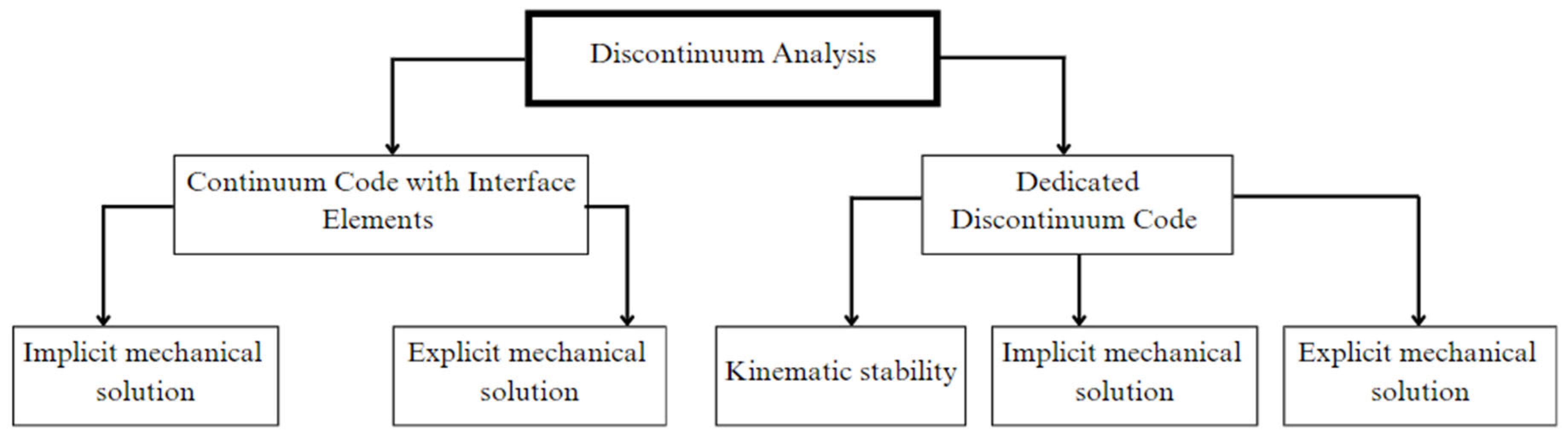
5.1. Discontinuum Modeling

Discontinuum numerical simulation is a powerful approach used to simulate the behavior of fractured or jointed rock masses, particularly in scenarios where the discontinuous nature of the material plays a critical role. Discontinuum numerical methods are mainly divided into two main groups, modified continuum codes, explicitly representing discontinuities, and numerical techniques specially designed to analyze discontinuous systems, as shown in Figure 11. Unlike continuum-based methods, which assume the material is homogeneous and continuous, discontinuum modeling explicitly represents the rock as an assembly of discrete blocks, particles, or elements. This approach enables the detailed simulation of fracture initiation, propagation, interaction, and coalescence, capturing complex small-scale phenomena that are critical for understanding hydraulic fracturing at laboratory scales. By incorporating the inherent heterogeneity of rock materials and the mechanical behavior of pre-existing and newly formed fractures, discontinuum models provide valuable insights into fracture mechanics, fluid flow through fractured media, and the overall response of rock masses under stress.

5.1.1. Discrete Elemental Methods

The preliminary purpose of the discrete element model was to study the molecular dynamics studies, which was further expanded to other engineering studies by Cundall and Strack [113]. This simulation method precisely calculates the finite particle displacement and rotations to perform contact detection for an assembly of particles. Pine and Cundall [114] considered the pioneer application of the discrete element method (DEM) for the numerical simulation of the hydromechanical response of the reservoir as a result of fluid injection in hydraulic fracturing operations. DEM tools such as PFC2D, PFC3D, UDEC, and 3DEC are widely used for hydraulic fracturing numerical simulation. Chang, Yun [115] used the PFC to study the deformation and fracturing in metamorphic and igneous rocks by simulating stress–strain experiments. The DEM is not only useful for the stress–strain laboratory experiments of geomechanical characterization but also for the acoustic emission studies of fractures in hydraulic fracturing. Al-Busaidi, Hazzard [116] studied the after-effects of hydraulic fracturing to understand the induced seismicity, which may cause environmental hazards. It is possible to model such processes by DEM methodologies [117]. The DEM has the capability to model the bedding planes in the form of particle contacts and their effect on the hydraulic fracturing parameters [118]. The natural fractures in the bedding plane change the estimated hydraulic fracturing design, which can be modeled by the DEM to study the interaction at a microscopic level [119,120]. Nasehi and Mortazavi [121] found that reservoir heterogeneities may contribute negatively to hydraulic fracture propagation and decrease the efficiency of the fracturing process. The constituent of fracturing fluid controls the fracture width and length of the fracture in hydraulic fracturing. These fluids often react with rock, creating several reaction by-products that may reduce the fracture aperture and produce a larger plastic zone [122]. Marina, Derek [123] used fluid–solid coupling to analyze the natural fracture orientation control on the hydraulic fracture attributes and their interaction with the stress state. The flexibility in the software to modify these codes according to the study gives more room to alter the numerical simulation according to their needs. The modified DEM codes have been widely used to assess the fluid injection rate, the anisotropy of laminated rocks, and the perforation parameters in hydraulic fracturing processes. It was seen that a larger in situ stress ratio, a smaller difference in the in situ stresses, higher injection rates, and weak structural integrity are helpful to achieve desirable results in hydraulic fracturing [124,125]. Liu, Ma [126] used DEM numerical simulation to study the hydraulic fracturing in the heterogenous reservoir. Although PFC is very good in representing grain-scale processes in hydraulic fracturing, it often faces problems in the simulation of the joint influence on hydraulic fracture initiation and propagation, has a larger consumption of computation resources, and has difficulty in fracture geometry control. He, Zhu [127] used UDEC to simulate hydraulic fracturing in heterogeneous rocks, and its reliability was validated against previous laboratory experiments. They concluded that hydraulic fracture propagation is directed by perforations if the formation is heterogeneous, while stress variation is the main factor to control fracture propagation in homogeneous formations. Zhang, Damjanac [128] investigated the impact of pre-existing discrete fracture networks (DFNs) on hydraulic fracture propagation and reservoir stimulation effectiveness. They demonstrated that weak, permeable DFNs significantly influence the fracture slip, fracture–rock interaction, and stimulation efficiency. Using numerical models based on the DEM and the fracture network engineering approach, they provided a framework for analyzing coupled processes in complex geological settings where explicit fracture representation is critical, as shown in Figure 12.
With a change in the stress regime, the cohesive forces in the rock matrix are changed significantly, which leads to sand production in the flow. Yazdani, Fatehi Marji [129] investigated the impact of hydraulic fracturing on sand production in sandstone reservoirs by using 2D discrete element models in PFC2D 5.0 software developed by Itasca consulting, Minneapolis, United States. They simulated fractures with varying lengths relative to well radii and analyzed the effects of fracture orientations (90° and 180°). Their findings highlight how fracture configurations influence sand production rates, providing insights to optimize reservoir recovery and wellbore stability.

5.1.2. Discontinuous Deformation Analysis

Discontinuous deformation analysis (DDA) was developed for numerical studies of the mechanical behavior of the discontinuous blocks related to geotechnical engineering [130,131]. The treatment of the simulated model as a set of blocks connected with virtual contacts is the main principle behind DDA [132,133]. DDA simulates all of the static and dynamic processes related to the deformable domain through the repetitive convergence of the contact states. Kim, Amadei [134] were among the early researchers who extended the DDA method to address the following three key limitations: modeling water–block interactions with hydromechanical coupling, simulating sequential loading/unloading, and incorporating rock reinforcement techniques such as rockbolts and shotcrete. With time, several extensions have been made to improve the performance of the 2D-DDA and 3D-DDA methods; second-order grided DDA [135], Lagrangian DDA [136], MLCP-DDA [137], and BE block DDA [138] were some of the modifications to 2D-DDA. The concept of parallel computing improved the computational efficiency of 3D-DDA simulation to solve geotechnical problems [139].
DDM has been widely used for the simulation of hydraulic fracturing and the cross-validation of results with lab-scale experimentation. DDA has also been coupled with other continuum and discontinuum approaches for the specific study of engineering problems. The addition of a fluid network model to DDA gives us the flexibility to study fracture initiation and propagation with the injection of fluid. The results of DDA can be matched with the experimental and analytical solutions for cross-validation [140]. The improvement in the different parts of DDA, such as fluid, contact, and coupling components, increases the overall accuracy and stability of the hydraulic fracturing solution. The addition of a finite volume fracture network model in DDA can be used to study fracture propagation by high-viscosity fracturing fluid in the impermeable medium. Morgan and Aral [141] presented a more stable and accurate solution of hydraulic fracturing with an improvement in the classic code of DDA, which matched well with the triaxial laboratory testing of hydraulic fracturing. Choo, Zhao [142] integrated a hydraulic crack initiation–propagation extension into a hybrid model by combining DDA and finite element meshes, enabling the simulation of continuum and discontinuum problems. The extension included a coupled hydromechanical analysis algorithm designed for hydraulic fracturing simulations. They also compared the DDA simulation of laboratory testing with DEM and the experimental results of geomechanical characterization. The application of 2D-DDA for the 3D numerical simulation of hydraulic fractures of specific heights is not possible without necessary modification. The new methodology of extended discontinuous deformation analysis by Hu, Li [143] successfully investigated 3D hydraulic fractures by 2D-DDA, which created a successful milestone for the optimization in shale gas production in Longmaxi shale. The introduction of natural fractures in the DDA remains a challenging task. The inclusion of natural fractures in the DDA numerical simulation increases the complexity of the problem, but it is possible to validate the results through comparison with laboratory testing, as shown in Figure 13 [144].
The capabilities of DDA are further enhanced by coupling and modifying the codes so to attain a hydro-mech-chemical solution in hydraulic fracturing [145]. Hu, Li [146] developed a fully coupled DDA model for the simulation of hydromechanical processes in fractured porous media, incorporating fracture seepage, pore seepage, and fracture network propagation. The work shows that DDA can model the geomechanical problem related to fluid interaction in fractured reservoirs.

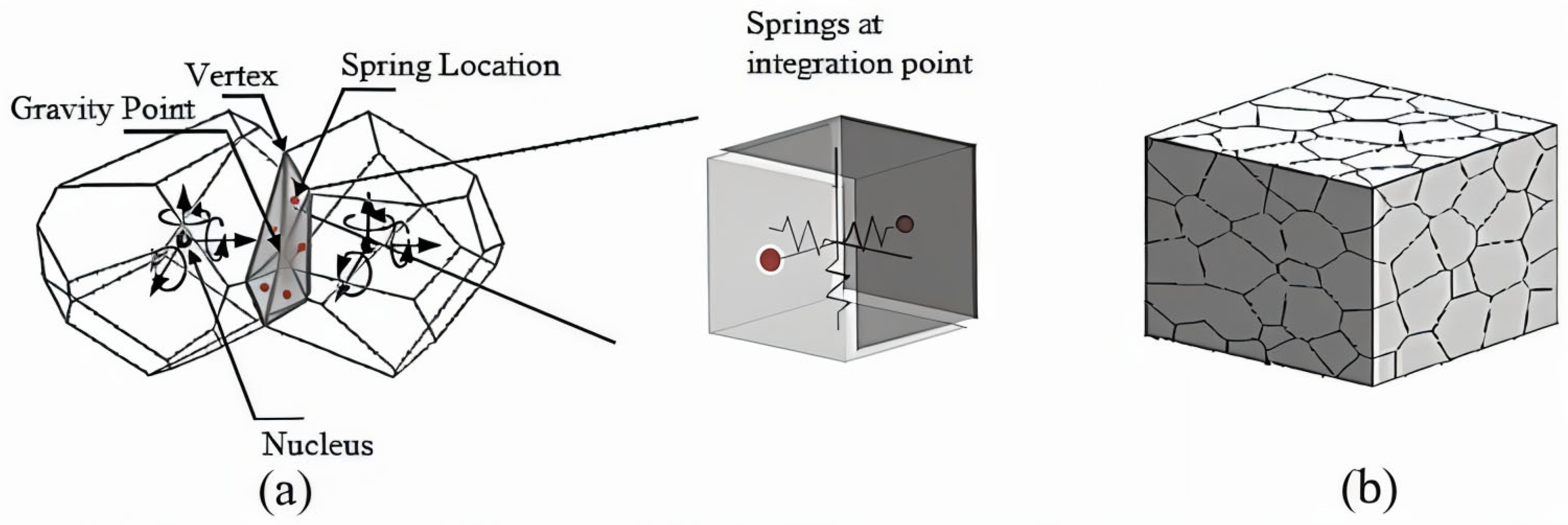
5.1.3. Rigid Body Spring Network

Initially, the rigid body spring network (RBSN) was developed by Kawai [147] to analyze the seismic response of structures. In this method, the structure is divided into discrete rigid bodies connected by springs (Figure 14). The primary objective was to reduce the computational resource requirements compared to the finite element method. It is assumed that rigid bodies do not deform except through overlapping and separation. Elastic homogeneity was introduced into RBSN simulations using Voronoi polygon discretization [148]. The motion of each cell was determined by the displacement of its centroid (u, v, θ1). The cell displacement can be defined as
u = u 1 ( y y 1 ) θ 1
u = v 1 ( x x 1 ) θ 1
The thermal and mechanical aspects of the discontinuum hydraulic fracturing process are possible with the integration of RBSN with other software for the detailed study of the fracture propagation, fluid flow, and transport in the reservoir [150]. RBSN effectively combines with TOUGH2 due to the sharing of the common utilization of nodal points, as well as the model formulation and interpretation of results [151]. Asahina, Houseworth [152] used the numerical simulation of the RBSN and TOUGH2 coupling capabilities for the simulation of fracture development in geomaterials, and compared the results with RBSN-FLAC and laboratory testing. Kim, Rutqvist [153] developed a coupled hydromechanical model for hydraulic fracturing through the integration of RBSN with TOUGH2 v.2.0 software developed by Lawrence Berkeley National Laboratory, Berkeley, United States. TOUGH2 was used for the multiphase flow, which was combined with RBSN’s fracture initiation and propagation. The numerical simulation results were validated by 2D analytical solutions and the laboratory testing of cubic soda–lime glass samples. The fluid viscosity, natural fracture strength, and confining stress were assessed with a sensitivity analysis to understand the controlling factors on the numerical simulation of hydraulic fracturing (Figure 15).
Rasmussen, de Farias [154] improved the RBSN method for the realistic simulation of fracturing in brittle rocks. They simulated the cohesive zone model, rock heterogeneity, and natural fractures in the RBSN simulation model. The numerical results were matched with experimental data from the granite laboratory testing. The fracture could be successfully represented by RBSN bonds, while its propagation was possible with CZM in the numerical study of the anisotropic deformation, strength, and fracture propagation in hydraulic fracturing [155]. Potyondy and Fu [156] used the Voronoi-shaped grain model in RBSN for the accurate replication of rock microstructures and damage mechanisms at the grain scale, including the heterogeneity, microcrack closure, and grain breakage. The successful matching of the RBSN results with the laboratory testing showed that RBSN is equally efficient in the numerical simulation of all hydraulic fracturing processes at the laboratory scale.

5.1.4. Variants of Virtual Internal Bond

The virtual internal bond (VIB) model is a micromechanical approach used to simulate mechanical failure through a network of nonlinear force–displacements governed virtual bonds. The variants of the VIB were introduced to capture the dynamic damage evolution across different materials (Figure 16). This modification to the VIB was used to incorporate heterogeneity, thermal behavior, rate dependency, and multi-scale behavior. A VIB model was developed by Klein and Gao [157], and was further modified for crack initiation and growth [158]. In the VIB mechanism, the mechanical behavior of the bonds is governed by the Cauchy–Born rule of crystal elasticity, which relates the strain energy from the macroscale to the microscale. It is possible to express Poisson’s ratio in terms of the normal bond stiffness (Kn) and shear bond stiffness (Ks) instead of using a constant value by varying the virtual internal bond properties [159].
Zhang [161] introduced a novel approach to simulate natural fractures in heterogeneous reservoirs without altering the meshing scheme. It was observed that fracture propagation is dependent on micro-bond rupture for all modes of fracture failure. After suitable modifications to the VIB model, the need for an additional fracture criterion can be eliminated. Zhang and Ghassemi [162] developed a three-dimensional Virtual Multidimensional Internal Bond (VMIB) model to simulate realistic fracture propagation by linking microscale bond rupture to macroscale fracture behavior. The model incorporated a 3D finite element method and a partition approach to account for the contact and friction between fracture faces. Numerical simulations validated against experimental data demonstrated accurate fracture propagation and coalescence. The discrete VIB model is a lattice-based approach that simplifies three-dimensional seepage and mechanical behavior into one-dimensional bond interactions. It allows fractures to pass through bond cells, embedding them within the background mesh. This method effectively simulates hydromechanical coupling in complex reservoirs [163] (Figure 17). The DVIB model has proven to be a viable solution for modeling the effects of loading rates on the fracturing process in rocks.
The thermal–hydraulic–mechanical–chemical THMC-DVIB model extends DVIB to simulate thermal–hydraulic–mechanical–chemical (THMC) coupling in acid fracturing. It integrates temperature effects on acidization and mechanical deformation within a unified bond framework, simplifying complex THMC interactions, and making it particularly effective for geothermal carbonate reservoir simulations [164]. The quasi-3D discretized VIB model is an effective simulation method for fracture acidizing in carbonate reservoirs. Complex hydrochemical coupling can be reduced to a one-dimensional bond dissolution problem, improving the computational efficiency for acid transport. This model accurately represents etching behaviors and the fracture acidizing process [165]. The VIB model is one of the most effective methodologies for simulating complex hydraulic fracturing processes through modifications to the basic mathematical framework. Overall, DVIB and VMIB are similar approaches based on the DEM, with the key distinction that DVIB incorporates nonlinear elasticity (Table 5).

5.2. Integration of Numerical Simulation and Machine Learning Methods

The integration of discontinuum modeling and machine learning (ML) methods for hydraulic fracturing is an emerging area of research that combines advanced computational mechanics with data-driven approaches to improve the understating, prediction, and optimization of the hydraulic fracturing processes. Discontinuum modeling can be used for different aspects of hydraulic fracturing but requires a lot of computational resources for the prediction of the hydraulic fracturing geometry [170]. The most commonly used ML methods for hydraulic fracturing include classification and prediction models. Researchers have used ML for both different simulation input parameters and simulation optimization, for instance, in the dynamics of reservoir production [171], hydraulic fracture interaction with natural fractures [172], the treatment pressure in hydraulic fracturing jobs [173], and reservoir characterization [174,175,176,177]. Lizhe, Fujian [178] used ML for the hydraulic fracturing completion design by optimizing the treatment parameters for maximum profitability. The data generated from reservoir simulation models were input into the ML models to predict the net present value of hydraulic fracturing treatments. Yan and Zhong [179] demonstrated the potential of deep reinforcement learning for hydraulic fracturing optimization, allowing for real-time, additive decision making to enhance the oil recovery and maximize the economic returns. ML models are also used to prepare reservoir models for hydraulic fracturing simulations. Santoso, He [180] used U-Net methods to automate the fracture identification in fracture reservoir modeling. They replaced the manual interpretation of fractures with artificial-driven segmentation, which improved the accuracy, efficiency, and scalability, making this a significant tool for reservoir simulation.
Although the contribution of ML in the numerical simulation of hydraulic fracturing is not quite prominent, there are certain limitations to the integration of ML with numerical simulation. ML is based on statistical correlations rather than physical causality. As a result, this integration may face struggles in the capture of the complex physics of hydraulic fracturing reservoirs. These methodologies often act as a black box in which the conservation laws are not significant. The requirements of large datasets for ML methods can be covered by physics-based artificial intelligence approaches [181]. The behavior of ML is rigid for trained datasets and lacks optimized generalization, which leads to doubtful results in highly heterogeneous reservoirs [182].

6. Discussion

Hydraulic fracturing is an important approach for creating the artificial ability of unconventional reservoirs to produce hydrocarbons. It is also used in enhanced geothermal systems to increase the permeability in igneous and other rock types for water circulation. Although it has numerous applications, it is always associated with environmental concerns. One of the major risks attached to hydraulic fracturing is the potential contamination of groundwater resources. Any leakage of injected fluids or improper handling of fracturing fluids may contaminate freshwater reserves at shallow depths. In highly tectonically active areas, hydraulic fracturing may contribute to seismic activity. The injected fluid reduces the effective stress and triggers fault slips, leading to locally induced seismicity. Such problems can be minimized through improved well integrity monitoring, seismic risk assessment, and water recycling.
The extension of laboratory-scale hydraulic fracturing research work faces a lot of problems when being used at the field scale. The consideration of scaling factors is a bridge to expand the laboratory testing of hydraulic fracturing assessments at the field level, which needs to be addressed in all types of hydraulic fracturing experimentation. In addition, some essential conditions of field operations for hydraulic fracturing are often overlooked in laboratory experiments, such as the influence of in situ stresses, geological features, and temperature and pressure. One way to consider all of the related factors of hydraulic fracturing in a study is through numerical simulation at a laboratory scale. Uniaxial, biaxial, and true triaxial stress-based apparatuses modify their scope of testing depending upon the consideration of financial and technological improvements. The major factors affecting hydraulic fracturing have been studied by numerical simulation by several authors. Still, several gaps have been identified in the applied testing approach, which are articulated in the discussion sections below.

6.1. In Situ Stress Conditions

The successful application of hydraulic fracturing at the laboratory scale depends on the similarity between the lab and field conditions. Among the key parameters, stress conditions significantly influence the fracture geometry, initiation, and propagation. Stress differences play a dominant role in fracture propagation, surpassing the geomechanical properties, fluid pressures, and geological structures. In field conditions, stress magnitudes vary in all three directions, unlike the simplified uniaxial and biaxial stress states in laboratory experiments. These stress variations govern the formation of both primary and secondary fractures [10].
Zhang, Si [30] investigated the stress evolution during hydraulic fracturing using DEM numerical simulations and found that shear stress along the fracture trace minimized at maximum differential stress under triaxial conditions. While uniaxial testing has been employed to study frictional effects [52], fracturing mechanisms, fracture orientations [81], anisotropy [82,84], and viscosity effects [50], it does not fully replicate in situ stress magnitudes and orientations, thus limiting its applicability. Addressing this gap requires advanced experimental methodologies supported by enhanced financial and technical resources. Numerical simulations provide a more accessible approach to studying hydraulic fracturing under in situ stress conditions, whereas laboratory replication demands substantial investment [183].
Understanding the stress contributions to the hydraulic fracturing process is crucial for optimizing operations in unconventional reservoirs. Biaxial testing has been used to analyze the stress effects on fracture initiation and propagation. Wang, Gong [95] demonstrated that stress distribution influences the fracture orientation, with higher in situ stress ratios increasing the breakdown pressure in granite. In contrast, in coal reservoirs, stress constraints improve the hydraulic fracturing efficiency by reducing the fracture pressure. Similarly, Wang, Elsworth [88] used biaxial testing to assess the impact of stresses and pore pressure on the fracture behavior in coal samples, observing that higher stress differentials induce secondary fractures. Variations in the stress magnitudes affect the fracture propagation dynamics [106], influenced by the injection wellbore orientation, viscosity–stress interactions, and multi-well injections. Fatahi, Hossain [184] employed DEM numerical simulations to determine the fracture initiation and breakdown pressure in sandstone under true triaxial stress, finding strong agreement with the experimental results, which indicated fracture alignment along the maximum horizontal stress (Figure 18).
Laboratory hydraulic fracturing experiments provide insights into the governing factors, but discrepancies with field conditions, such as fluid–rock interactions, the wellbore orientation, and stress variations, limit their direct applicability. Simplified assumptions in uniaxial, biaxial, and triaxial tests reduce the adaptability and accuracy of the experimental results. Enhancing experimental setups to incorporate advanced mechanisms can improve the representation of viscosity–fracture interactions, stress variations, and wellbore orientation effects for field applicability. Weak in situ stress assumptions in analytical and experimental methods introduce deviations from numerical simulations. Coupling analytical studies with numerical models enhances the understanding of in situ stress contributions to hydraulic fracturing. The adaptability of true triaxial machines in replicating field stress conditions makes them superior to other laboratory methods for hydraulic fracturing design. Correction factors in uniaxial and biaxial experiments may help to bridge the gap between laboratory and field stress conditions, ensuring more accurate interpretations for practical applications. Future research should focus on refining experimental techniques and integrating numerical models to better represent in situ stresses, ultimately improving the predictive accuracy of hydraulic fracturing applications in field conditions.

6.2. Geological Conditions

Laboratory experiments usually use limited heterogeneous samples to investigate the different aspects of hydraulic fracturing, including fracturing initiation, propagation, and geometry. Although these tests give valuable insight into hydraulic fracturing, they may not accurately represent the reservoir’s physical condition, which limits the application of these tests in realistic conditions. Faults, bedding planes, and discontinuities affect the orientation and geometry of hydraulic fractures. Reservoir heterogeneities impact the geomechanical properties of the rock, such as Poisson’s ratio, Young’s modulus, the shear modulus, etc. The reservoir heterogeneities due to the variation in layers in the reservoir influence the hydraulic fracturing. The change in the geomechanical properties disturbs the uniformity in the minimum horizontal state of stress, affecting the vertical fracture growth. The geomechanical properties of the fractured rocks and the petrophysical properties of the nearby rocks control the width of the fracture growth across the interface (Figure 19) [185]. The brittle rock fractures earlier as compared to ductile sections of the reservoir [186,187].
Asahina, Pan [189] developed and applied the TOUGH-RBSN simulation tool for modeling hydraulic fracturing in geological media. Their work integrated TOUGH2 for mass transport with an RBSN to simulate the fluid pressure-induced fractures and fracture-assisted flow. The model was validated through laboratory-scale hydraulic fracturing tests in granite, analyzing the effects of fluid viscosity on the injection pressure and fracture evolution (Figure 20).
Uniaxial, biaxial, and triaxial testing have been used to study the effects of natural fractures on the generation and propagation of hydraulic fractures. The results of the geomechanical testing can be coupled with other computational approaches for the prediction of natural fractures in unconventional reservoirs [190]. Statistical methods, empirical equations, and machine learning are often employed as indirect methods to identify natural fractures [190,191]. Liu, Liang [84] studied the bedding plane’s impact on shale hydraulic fracturing. However, while the author considered the bedding plane, they ignored the other types of heterogeneities, creating a weakness in the work. The existence of natural fractures improves the hydraulic fracturing potential of the rock. The mutual interaction of natural–hydraulic fractures depends on the horizontal stress difference, rock–fluid interaction, and fracturing pressure. The natural fractures can offset, intersect, or restrain the hydraulic fractures depending on the conditions [11,188,192]. The experimentation on the rock samples with natural fractures mimics the external appearance of the discontinuities, but such an approach still neglects the persistence and directions of the natural fractures. The contribution of the natural fractures using artificial samples offers more control over the experimental conditions, but considering completely realistic conditions is still impossible. Artificial material plates of uniform thickness are often added to the synthetic samples to show the natural fractures, but natural fractures have heterogeneous thicknesses in real conditions. The tortuosity, aperture, and permeability of the natural fractures also ignore the natural conditions. In such difficult conditions, numerical simulation plays an important role in studying the comprehensive control of natural fracture interactions with hydraulic fracturing. Fu, Huang [193] used numerical simulation to study the contribution of natural fracture attributes with hydraulic fractures under different geological and engineering conditions.
The laboratory samples also ignore the effects of the fracture filling material, which may impact the shear strength of the fractures. Better and applicable results related to hydraulic fracturing are only possible by studying samples representing different reservoir conditions along with controlled experimentation using artificial samples. Three-dimensional printing technology can be critical in developing cores that may replicate natural fracture conditions. The synthetic cores from 3D printing can show grain size heterogeneities, the orientation of bedding planes, and the lithology. The assistance of laboratory testing with proper scaling factors allows for a more comprehensive interpretive application. The reliability and accuracy of the results will improve with the cross-validation of the results with field data.

6.3. Temperature and Pressure Conditions

Temperature and pressure are very important factors that influence the geomechanical and petrophysical behavior of the rock during hydraulic fracturing experimentation, but those are often overlooked in laboratory studies. Many researchers have worked on this feature and highlighted its importance in fracture initiation, propagation, and geometry in subsurface reservoirs. The initiation pressure of the hydraulic fracturing reduces due to thermal damage of the granite samples. Higher ranges of crack growth are seen due to thermal shocks caused by increased temperature [194]. The strength of the fine-grained sandstone increases with an increase in the temperature, but such a trend reverses in mudstone for the same temperature range in both lithologies [61].
For the same range of temperature, the strength of fine sandstone increases with temperature but decreases in mudstone (Figure 21). This shows that the effects of temperature depend upon the lithological attributes of reservoir rock. The complexity and length of fractures are directly related to the temperature. The XS1 fine sandstone sample had a higher silica content than the mudstone samples (FS1, FS2, FS3, and FS4), leading to a comparatively complex fracture geometry. The effects of the confining pressure and temperature in granite can be studied using triaxial testing and numerical simulations [195]. The results showed that increasing the temperature and confining stress generally increased the fracturing pressure and decreased the fracture aperture and length. The complexity of the fractures increased with an increase in the temperature. Such behavior is dominant in mudstone compared to sandstone reservoirs (Figure 22). It is possible to simulate all of the effects of pressure and temperature on hydraulic fracturing by coupling the hydromechanical behavior with thermal simulators. Taron, Elsworth [196] combined the thermal, hydraulic, and chemical processes of TOUGHREACT with the mechanical analysis of FLAC3D in fractured rock media. Various aspects of hydraulic fracturing, such as the stress difference, mineral reactions, and mechanical deformation, were studied using thermal–hydrologic–mechanical–chemical simulation.
Shu, Zhu [197] studied the effect of the temperature and confining pressure on hydraulic fracturing by the triaxial testing of granite. The result of the confining pressure on the fracture aperture (be), permeability (ke), and hydraulic conductivity (K) are further intensified with an increase in the temperature. Permeability is mainly dependent upon the material, while hydraulic conductivity is controlled by both the material and fluid characteristics. The excessive matching of the permeability and hydraulic conductivity trend showed that fluid has a minor effect on the hydraulic conductivity. The effect of the temperature was almost the same for the flowing capacity of the rock. The aperture and conductivity of the hydraulic fracture in granite decreased with an increased confining pressure. The impact of the temperature was significant at higher confining pressures greater than 9 MPa. The main reasons behind the decrease in the reservoir properties with the confining pressure were due to decline in the moduli of the rock with an increase in the temperature and the reduction in the porosity of the rocks due to an increasing confining pressure (Figure 23).
The cited work highlights the significance of temperature and confining pressure in influencing variations in hydraulic fracturing properties. These conditions need to be thoroughly followed in the laboratory experimentation of hydraulic fracturing, which reduces the accuracy and reliability of the results. The temperature and confining pressure conditions still need to be fully achieved due to the restrictions of the apparatus. The difference in laboratory and reservoir temperatures change the conditions of fracture initiation and rock failure. Uniaxial testing entirely ignores the reservoir’s confining pressure conditions, showing the inferiority in the reliability of the results compared to the true triaxial testing. Using temperature and confining pressure mechanisms will improve the generalization of the results and interpretation at a broader scale.
A combination of reservoir and outcrop samples and controlled experimentation on artificial samples will increase the accuracy of the laboratory testing. The similarity of laboratory testing with the ambient reservoir conditions enhances the scope of the experiment. Properly representing the pressure and temperature in hydraulic fracturing experimentation requires accurate reservoir characterization. Sensitivity analysis is fundamental to studying the effect of temperature and pressure at broader reservoir conditions. The results of the laboratory-scale hydraulic fracturing can be extended to field-scale operations based on a comprehensive understanding of the scaling effects, geological conditions, and geomechanical behavior under in situ reservoir conditions. Laboratory-scale samples are much smaller than field reservoirs, which causes the difference in the stress distribution and fracture geometry. The viscosity, leak-off characteristics, and rock–fluid interaction may vary between laboratory testing and field conditions due to differences in the pore pressure, temperature, and pressure gradients. These limitations can be handled marginally by dimensionless scaling laws, but ideal matching necessitates additional numerical simulation and field data.
The scaling factors can extend laboratory information to field applications, but reservoir properties causing high heterogeneity are missing, which reduces the generalization for different geological scenarios. The shortcomings of the laboratory experiment can be handled by coupling the capabilities of the numerical simulation of hydraulic fracturing [198]. However, the accuracy of these models is highly dependent upon the input parameters and assumptions. Oversimplified assumptions, such as homogeneous, elastic, and isotropic rock behavior, and other structural features, may neglect the heterogeneous features, which may cause difficulty in extending the laboratory simulation to field-scale applications. Future advancements in data-driven machine learning models, real-time monitoring, and the adaptive fracturing and calibration of the numerical models must be calibrated with field data, such as microseismic monitoring, well logs, and pressure data, which can increase the generalization and accuracy of the simulation models.
Numerical simulation is one of the most effective methodologies for studying aspects of hydraulic fracturing that are not feasible through extensive laboratory testing due to limited resources and time. The smaller-scale processes of hydraulic fracturing experiments can be modeled using discontinuum modeling. The DEM effectively models hydraulic fracturing processes in reservoirs by representing the rock fabric as small particles. The consideration of heterogeneities in the DEM depends on the size of the particles in the model and faces challenges in simulating fractured media. In this regard, DDA is regarded as a more practical approach for modeling fractured media in hydraulic fracturing by representing the rock structure as blocks. The flexibility of DDA to integrate with other approaches provides an additional advantage. The increased complexity of fractures in DDA can be managed by comparing the simulation results with laboratory testing. The computational resources required for the RBSN method are lower compared to the FEM. Similar to other approaches, the numerical simulations of the RBSN are comparable to laboratory testing results. There are certain uncertainties and limitations in the numerical simulation of hydraulic fracturing, which can be due to model calibration, geological data integration, and simplification in numerical simulation approaches. Model calibration with field data is an important step to reach an applicable and reliable conclusion from numerical simulation. The limited field data, such as in situ stress conditions, fracture geometry, and fluid properties, are often marginally available, which makes it difficult to have accurate calibration. The idealized assumptions, such as the linear elasticity, uniform rock properties, isothermal conditions, etc., create differences between the modeled and real complexities. Geological uncertainties significantly affect the accuracy of the numerical simulation. The spatial variability in the porosity, permeability, and natural fracture network is immense, which are often considered as average or interpolated values. Such average values may introduce local effects and reduce the generalization of numerical solutions. The integration of geological values from the sources of different resolutions creates errors in the simulation. The identification and consideration of natural fractures in the numerical simulation model is considered one of the most difficult problems to handle. The best way to solve this problem is by creating a geological model based on seismic, well log information, and core data. The other limitations include discretization errors, boundary and simplified fracture initiation and propagation conditions, and the unavailability of suitable computational resources. These aforementioned limitations can be handled through an iterative approach that combines the numerical simulation with field data, machine learning for pattern recognition, and probabilistic methods for handling the uncertainties.
The costs associated with experimental and numerical methods in hydraulic fracturing depend on various factors, such as the scale, location, equipment, specific study, and scope of the study. The costs related to laboratory-scale experimentation include the fracturing apparatus, rock core acquisition, fracturing fluids (especially if the fluid is other than water), laboratory labor and time, and operational costs. Field-scale fracturing jobs are much more costly than laboratory-scale testing. Field-scale experiments involve actual fracturing operations, reaching up to millions of dollars depending on the location, well depth, number of stages, and the complexity of the fracturing operations. The cost of a single well was USD 2.38 million between 2006 and 2010, which will likely be much higher when considering current economics [199]. Numerical simulations provide a viable solution for studying various aspects of hydraulic fracturing, ranging from micro- to megascale processes. However, there are still costs involved with numerical simulations, such as software and licensing, training, computational resources, technical labor, and data analysis.

7. Summary

  • Hydraulic fracturing experimentation has advanced with the rise of modern technology, helping to reach more reliable and applicable results for application in the field. This paper summarizes the recent advances in uniaxial, biaxial, and true triaxial testing, and their implications in hydraulic fracturing operations. This review article discusses the basic concepts of fracture models, scaling factors, and the nature of laboratory studies for hydraulic fracturing design. At the end of this article, the shortcomings of the laboratory apparatus regarding the lack of reservoir in situ stresses, geological, temperature, and pressure conditions were discussed.
  • The scaling factor is an essential aspect of laboratory testing for the accurate and reliable application of results in field operations. Laboratory-scale performance of the hydraulic fracturing experimentation requires that the testing material has a low fracture toughness and low permeability, and fractured by high-viscosity fracturing fluid. Small research efforts have been made to build a relationship between the laboratory and field operations of hydraulic fracturing through consideration of applicable scaling factors.
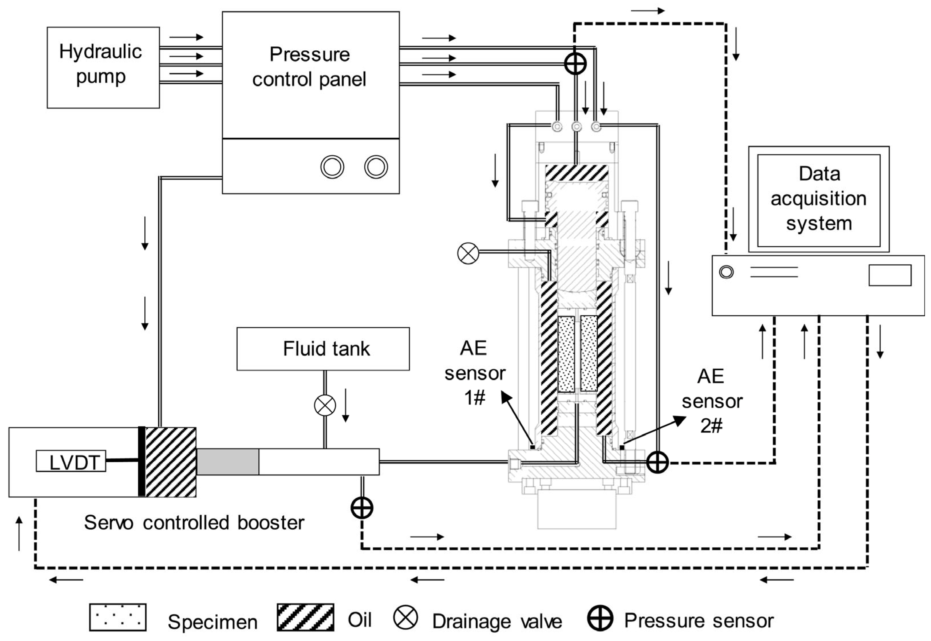
  • The main components of a basic hydraulic fracturing apparatus include a loading mechanism, fluid injection system, data monitoring, and other advanced sensors, depending on the research objectives. The nature of the loading system differentiates the hydraulic fracturing apparatus into uniaxial, biaxial, and true triaxial experimentation. The varying 3D loading conditions in true triaxial testing have the highest match with the field conditions of hydraulic fracturing. Adding advanced sensors related to the pore pressure, acoustic emission, temperature, stress distribution, and geological discontinuities will increase the adaptability of the results in field conditions. The hydraulic fracturing experimentation on samples from the field environment and the controlled artificial sample experimentation improve the interpretation of the results in more applicable ranges.
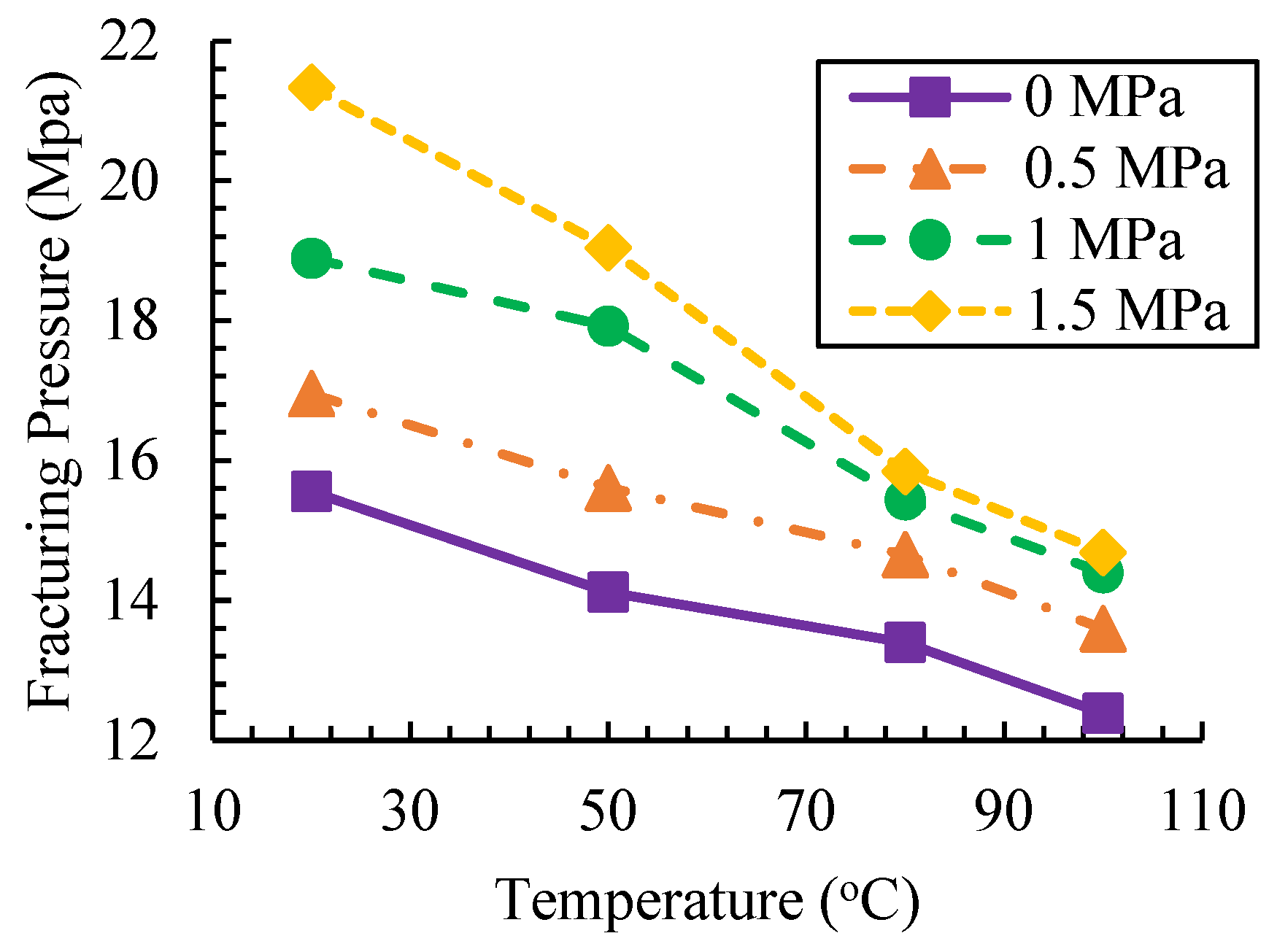
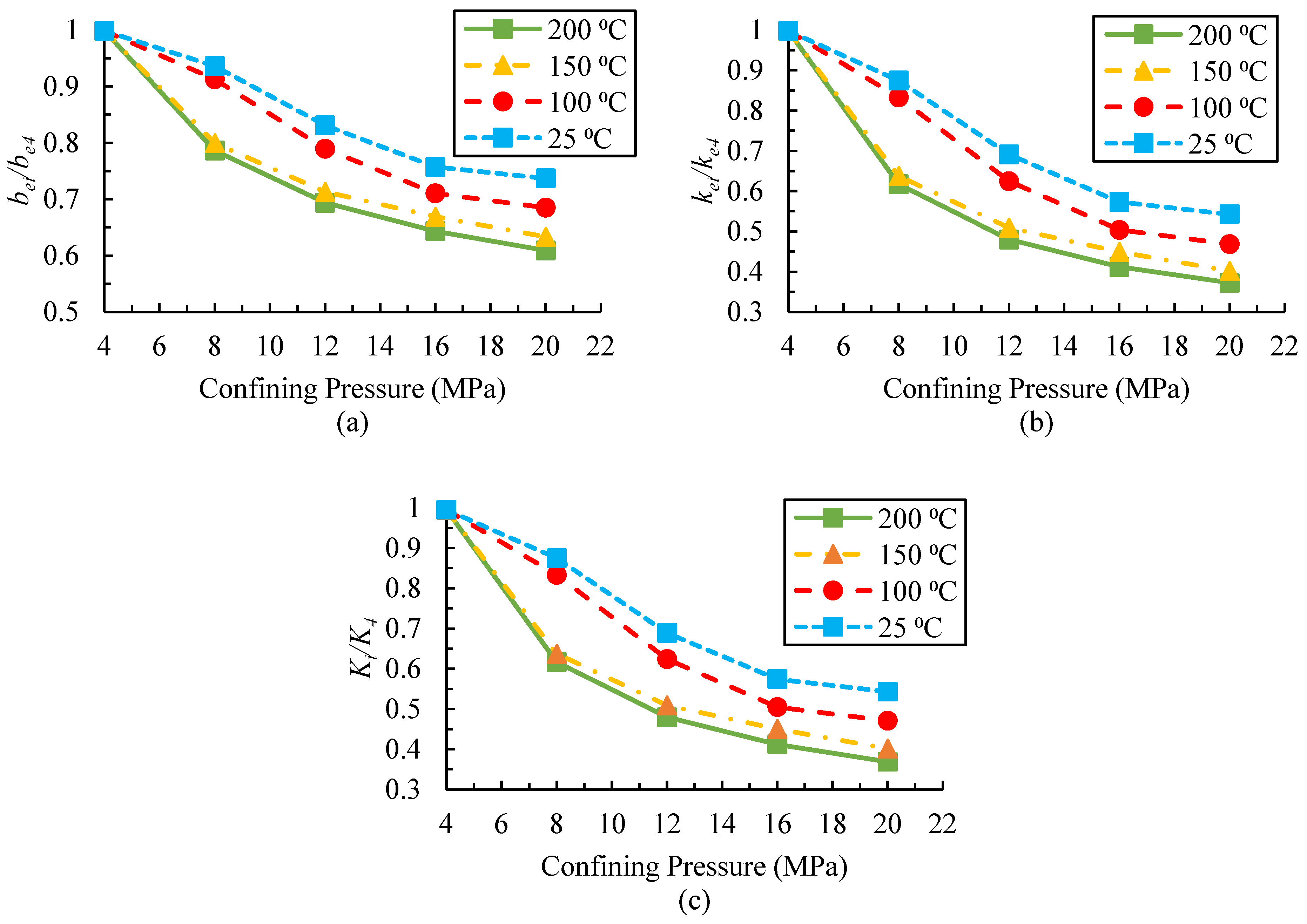
  • In situ stresses, geological conditions, temperature, and pressure influence the behavior of the hydraulic fracture. Stress differences significantly impact the fracture propagation more than the geomechanical properties, fluid pressures, and geological structures. Continuous stress distribution monitoring in samples needs to be improved in true triaxial apparatus. Simplified laboratory conditions may introduce errors in hydraulic fracturing testing. Natural–hydraulic fracture interaction depends on horizontal stress differences, rock–fluid interactions, and fracturing pressure. Unrealistic representations of natural fractures limit laboratory testing. Temperature effects vary with the reservoir lithology, impacting the fracture complexity and length. The temperature and confining pressure can reduce the fracture aperture and conductivity. A comprehensive understanding of the natural fracture contribution, temperature, and stress distribution requires combined laboratory, numerical, and field methods, including CT scans, microseismic data, pressure analysis, tracer testing, and production logging.
  • Laboratory-scale hydraulic fracturing experiments offer critical insights but are constrained by scaling effects, differences in the stress distribution, and reservoir heterogeneity. The limited size of laboratory samples fails to match the field scale, resulting in differences in the anticipated fracture initiation, propagation, and geometry. Discrepancies in factors such as the pore pressure, temperature, and pressure gradients may cause variations in the fluid behavior, leak-off, and rock–fluid interactions between the lab and field scales. Although numerical simulations help to bridge the lab findings to field applications, they often rely on simplified assumptions that overlook real-world geological complexities. Scaling factors may improve and generalize lab findings, but they are ineffective for highly heterogeneous reservoir features. The accuracy of numerical models can be enhanced by integrating machine learning, real-time monitoring, and adaptive fracturing techniques.
  • Hydraulic fracturing at the laboratory scale provides valuable insights into fracture initiation, propagation, and interactions with rock heterogeneities, but its limitations necessitate the use of numerical simulations for more comprehensive analyses. Numerical models, such as the DEM, DDA, and RBSN, effectively simulate complex mechanisms, including fracture–fluid interactions, stress redistributions, and the influence of the rock microstructure, thus enhancing our understanding of hydraulic fracturing processes. Advancements in these models, such as integrating nonlinear elasticity in VIB and coupling with finite element analysis or fluid network models, continue to improve the predictive accuracy and efficiency, especially in complex geological settings, offering promising applications for optimizing shale gas production, acid fracturing, and geotechnical engineering.
  • Future research should focus on combining microseismic monitoring, well logs, and pressure diagnostics to improve calibration from the nano- and microscale to the megascale. Advancements in high-resolution imaging and ML-driven tools have the potential to further refine predictive capabilities and bridge the gap between lab-scale insights and field-scale applications. More focus is required to design experimentation setups that can observe the fracture initiation and propagation dynamically. Currently, it is of uttermost importance to devise cheaper methods that may provide the capability to exert true triaxial loading. More efforts are required to develop open-access discontinuum simulators with extended flexibility to integrate the lab and field testing data.

Funding

The research received no external funding.

Data Availability Statement

This review paper does not involve original data collection; it is a compilation of existing literature. All of the referenced sources are appropriately cited, and readers are encouraged to refer to the original works for in-depth information and methodologies.

Conflicts of Interest

The authors declare no competing interests.

References

  1. Holditch, S.A. Tight gas sands. J. Pet. Technol. 2006, 58, 86–93. [Google Scholar] [CrossRef]
  2. Naik, G. Tight gas reservoirs—An unconventional natural energy source for the future. Accessado em 2003, 1, 2008. [Google Scholar]
  3. Belyadi, H.; Fathi, E.; Belyadi, F. Introduction to unconventional reservoirs. In Hydraulic Fracturing in Unconventional Reservoirs; Elsevier: Amsterdam, The Netherlands, 2017; pp. 1–12. [Google Scholar]
  4. Holditch, S.A. Hydraulic fracturing: Overview, trends, issues. Drill. Contract. 2007, 63, 116–118. [Google Scholar]
  5. Kumar, T.; Shandilya, A. Tight reservoirs: An overview in Indian context. In Proceedings of the 10th Biennial International Exhibition & Conference, Mumbai, India, 4–6 October 2013. [Google Scholar]
  6. Arthur, M.A.; Cole, D.R. Unconventional hydrocarbon resources: Prospects and problems. Elements 2014, 10, 257–264. [Google Scholar] [CrossRef]
  7. Gao, Q.; Cheng, Y.; Han, S.; Yan, C.; Jiang, L. Numerical modeling of hydraulic fracture propagation behaviors influenced by pre-existing injection and production wells. J. Pet. Sci. Eng. 2019, 172, 976–987. [Google Scholar] [CrossRef]
  8. King, G.E. Hydraulic fracturing 101: What every representative, environmentalist, regulator, reporter, investor, university researcher, neighbor and engineer should know about estimating frac risk and improving frac performance in unconventional gas and oil wells. In Proceedings of the SPE Hydraulic Fracturing Technology Conference, The Woodlands, TX, USA, 6–8 February 2012. [Google Scholar]
  9. Smith, M.B.; Montgomery, C. Hydraulic Fracturing; CRC Press: Boca Raton, FL, USA, 2015. [Google Scholar]
  10. Warpinski, N.R.; Mayerhofer, M.J.; Agarwal, K.; Du, J. Hydraulic fracture geomechanics and microseismic source mechanisms. SPE J. 2013, 18, 766–780. [Google Scholar] [CrossRef]
  11. Zhao, H.; Wang, X.; Liu, Z. Experimental investigation of hydraulic sand fracturing on fracture propagation under the influence of coal macrolithotypes in Hancheng block. J. Pet. Sci. Eng. 2019, 175, 60–71. [Google Scholar] [CrossRef]
  12. Cipolla, C.; Wright, C. Diagnostic techniques to understand hydraulic fracturing: What? why? and how? In Proceedings of the SPE/CERI Gas Technology Symposium, Calgary, AB, Canada, 3–5 April 2020.
  13. Van Der Baan, M.; Eaton, D.; Dusseault, M. Microseismic monitoring developments in hydraulic fracture stimulation. In Proceedings of the ISRM International Conference for Effective and Sustainable Hydraulic Fracturing, Brisbane, Australia, 20–22 May 2013. [Google Scholar]
  14. Dejam, M. Tracer dispersion in a hydraulic fracture with porous walls. Chem. Eng. Res. Des. 2019, 150, 169–178. [Google Scholar] [CrossRef]
  15. Dejam, M.; Hassanzadeh, H.; Chen, Z. Semi-analytical solution for pressure transient analysis of a hydraulically fractured vertical well in a bounded dual-porosity reservoir. J. Hydrol. 2018, 565, 289–301. [Google Scholar] [CrossRef]
  16. Wang, Y.; Zhang, H.; Lin, H.; Zhao, Y.; Liu, Y. Fracture behaviour of central-flawed rock plate under uniaxial compression. Theor. Appl. Fract. Mech. 2020, 106, 102503. [Google Scholar] [CrossRef]
  17. Stanisławek, S.; Kędzierski, P.; Miedzińska, D. Laboratory hydraulic fracturing tests of rock samples with water. Arch. Civ. Eng. 2017, 63, 139–148. [Google Scholar] [CrossRef]
  18. Sarmadivaleh, M.; Rasouli, V. Test design and sample preparation procedure for experimental investigation of hydraulic fracturing interaction modes. Rock Mech. Rock Eng. 2014, 48, 93–105. [Google Scholar] [CrossRef]
  19. Mao, R.; Feng, Z.; Liu, Z.; Zhao, Y. Laboratory hydraulic fracturing test on large-scale pre-cracked granite specimens. J. Nat. Gas Sci. Eng. 2017, 44, 278–286. [Google Scholar] [CrossRef]
  20. Lisjak, A.; Kaifosh, P.; He, L.; Tatone, B.; Mahabadi, O.; Grasselli, G. FDEM formulation for modelling fracturing processes in discontinuous. Comput. Geotech. 2017, 81, 1–18. [Google Scholar] [CrossRef]
  21. Eshiet, K.I.; Sheng, Y. An overview of principles and designs of hydraulic fracturing experiments and an inquiry into the influence of rock permeability and strength on failure mode. In Advances in Natural Gas Emerging Technologies; IntechOpen: London, UK, 2017. [Google Scholar]
  22. Huang, M.; Liu, D.; Hong, C.; Du, S.; Luo, Z.; Li, C.; Huang, Y. Representative sample sampling method for size effect experiment of jointed rock mass. Geofluids 2020, 2020, 1–8. [Google Scholar] [CrossRef]
  23. Cao, W.; Yildirim, B.; Durucan, S.; Wolf, K.-H.; Cai, W.; Agrawal, H.; Korre, A. Fracture behaviour and seismic response of naturally fractured coal subjected to true triaxial stresses and hydraulic fracturing. Fuel 2021, 288, 119618. [Google Scholar] [CrossRef]
  24. Zhong, Z.; Xu, C.; Zhang, F.; Wang, X.; Hu, Y. Size effect on hydraulic properties of rough-walled fractures upscaled from meter-scale granite fractures. Geomech. Geophys. Geo-Energy Geo-Resour. 2023, 9, 75. [Google Scholar] [CrossRef]
  25. Kashfi, M.; Shad, S.; Zivar, D. Evaluation of sample scale effect on geomechanical tests. Pet. Res. 2022, 7, 527–535. [Google Scholar] [CrossRef]
  26. Li, L.; Hu, J.; Li, S.; Qin, C.; Liu, H.; Chen, D.; Wang, J. Development of a novel triaxial rock testing method based on biaxial test apparatus and its application. Rock Mech. Rock Eng. 2021, 54, 1597–1607. [Google Scholar] [CrossRef]
  27. Shabdirova, A.; Bissekenova, Z.; Minh, N.H.; Kim, J.R. Sample preparation method of clay-rich sandstone analogue of sandstone reservoirs in Kazakhstan. In Proceedings of the ARMA US Rock Mechanics/Geomechanics Symposium, Houston, TX, USA, 26–29 June 2016. [Google Scholar]
  28. De Pater, C.; Beugelsdijk, L. Experiments and numerical simulation of hydraulic fracturing in naturally fractured rock. In Proceedings of the Alaska Rocks 2005, the 40th US Symposium on Rock Mechanics (USRMS), Anchorage, AK, USA, 25–29 June 2005. [Google Scholar]
  29. Deng, J.; Lin, C.; Yang, Q.; Liu, Y.; Tao, Z.; Duan, H. Investigation of directional hydraulic fracturing based on true tri-axial experiment and finite element modeling. Comput. Geotech. 2016, 75, 28–47. [Google Scholar] [CrossRef]
  30. Zhang, X.; Si, G.; Bai, Q.; Xiang, Z.; Li, X.; Oh, J.; Zhang, Z. Numerical simulation of hydraulic fracturing and associated seismicity in lab-scale coal samples: A new insight into the stress and aperture evolution. Comput. Geotech. 2023, 160, 105507. [Google Scholar] [CrossRef]
  31. Xie, L.; Jin, P.; Su, T.-C.; Li, X.; Liang, Z. Numerical simulation of uniaxial compression tests on layered rock specimens using the discrete element method. Comput. Part. Mech. 2019, 7, 753–762. [Google Scholar] [CrossRef]
  32. Liu, D.; Shi, X.; Zhang, X.; Wang, B.; Tang, T.; Han, W. Hydraulic fracturing test with prefabricated crack on anisotropic shale: Laboratory testing and numerical simulation. J. Pet. Sci. Eng. 2018, 168, 409–418. [Google Scholar] [CrossRef]
  33. Li, L.C.; Tang, C.A.; Li, G.; Wang, S.Y.; Liang, Z.Z.; Zhang, Y.B. Numerical simulation of 3D hydraulic fracturing based on an improved flow-stress-damage model and a parallel FEM technique. Rock Mech. Rock Eng. 2012, 45, 801–818. [Google Scholar] [CrossRef]
  34. Han, Z.; Zhou, J.; Zhang, L. Influence of grain size heterogeneity and in-situ stress on the hydraulic fracturing process by PFC2D modeling. Energies 2018, 11, 1413. [Google Scholar] [CrossRef]
  35. Qin, X.; Cai, J.; Wang, G. Pore-scale modeling of pore structure properties and wettability effect on permeability of low-rank coal. Int. J. Min. Sci. Technol. 2023, 33, 573–584. [Google Scholar] [CrossRef]
  36. Wang, Y.; Fu, H.; Liang, T.; Wang, X.; Liu, Y.; Peng, Y.; Yang, L.; Tian, Z. Large-scale physical simulation experiment research for hydraulic fracturing in shale. In Proceedings of the SPE Middle East Oil and Gas Show and Conference, Manama, Bahrain, 8–11 March 2015. [Google Scholar]
  37. Liberman, M. Hydraulic Fracturing Experiments to Investigate Circulation Losses. Master’s Thesis, Missouri University of Science and Technology, Rolla, MO, USA, 2012. [Google Scholar]
  38. Brenne, S.; Molena, M.; Stöckert, F.; Alber, M. Hydraulic and sleeve fracturing laboratory experiments on 6 rock types. In Proceedings of the ISRM International Conference for Effective and Sustainable Hydraulic Fracturing, Brisbane, Australia, 20–22 May 2013. [Google Scholar]
  39. Taherynia, M.H.; Aghda, S.M.F.; Fahimifar, A. In-situ stress state and tectonic regime in different depths of earth crust. Geotech. Geol. Eng. 2016, 34, 679–687. [Google Scholar] [CrossRef]
  40. Farkas, M.P.; Yoon, J.S.; Zang, A.; Zimmermann, G.; Stephansson, O.; Lemon, M.; Dankó, G. Effect of foliation and fluid viscosity on hydraulic fracturing tests in mica schists investigated using distinct element modeling and field data. Rock Mech. Rock Eng. 2018, 52, 555–574. [Google Scholar] [CrossRef]
  41. Yan, X.; Yu, H. Numerical simulation of hydraulic fracturing with consideration of the pore pressure distribution based on the unified pipe-interface element model. Eng. Fract. Mech. 2022, 275, 108836. [Google Scholar] [CrossRef]
  42. Qiu, R.; Zhang, G.; Zheng, X.; Luo, S.; Chen, H.; Zhao, J. Stress transfer law in laboratory hydraulic fracturing experiments. Sci. Rep. 2024, 14, 17287. [Google Scholar] [CrossRef]
  43. Ye, Z.; Ghassemi, A. Reexamining in-situ stress interpretation using laboratory hydraulic fracturing experiments. In Proceedings of the Unconventional Resources Technology Conference, Denver, CO, USA, 13–15 June 2023. [Google Scholar]
  44. Fan, P.; Liu, Y.; Lin, Z.; Wang, J.; He, Y.; Zhang, B. Physical Simulation Experiment Research for Hydraulic Fracturing in Tight Sandstone Reservoir Under Different Stress Conditions and Nature Fracture Combinations. In Proceedings of the 58th U.S. Rock Mechanics/Geomechanics Symposium, Golden, CO, USA, 23–26 June 2024. [Google Scholar]
  45. Jalili, S.; Ahangari, K. Effects of different stress regimes on hydraulic fracture geometry: A particle flow code approach. Innov. Infrastruct. Solut. 2017, 2, 41. [Google Scholar] [CrossRef]
  46. Shevtsova, A.; Stanchits, S.; Filev, E.; Karamov, T.; Stukachev, V.; Spasennykh, M. Assessment of Saturation Effect on Hydraulic Fracturing in Sandstone and Thermally Treated Granite. Minerals 2023, 13, 777. [Google Scholar] [CrossRef]
  47. Zhuang, L.; Kim, K.Y.; Diaz, M.; Yeom, S. Evaluation of water saturation effect on mechanical properties and hydraulic fracturing behavior of granite. Int. J. Rock Mech. Min. Sci. 2020, 130, 104321. [Google Scholar] [CrossRef]
  48. Jian, G.; Sarathi, R.S.; Burghardt, J.; Bonneville, A.; Fernandez, C.A. Effect of initial water saturation on the performance of fracturing fluids with and without polyallylamine under simulated EGS conditions. Geothermics 2023, 111, 102715. [Google Scholar] [CrossRef]
  49. Cuss, R.; Wiseall, A.C.; Hennissen, J.A.I.; Waters, C.N.; Kemp, S.J.; Ougier-Simonin, A.; Holyoake, S.; Haslam, R.B. Hydraulic Fracturing: A Review of Theory and Field Experience; British Geological Survey: Nottingham, UK, 2015. [Google Scholar]
  50. Bennour, Z.; Ishida, T.; Nagaya, Y.; Chen, Y.; Nara, Y.; Chen, Q.; Sekine, K.; Nagano, Y. Crack extension in hydraulic fracturing of shale cores using viscous oil. Rock Mech. Rock Eng. 2015, 48, 1463–1473. [Google Scholar] [CrossRef]
  51. Xing, Y.; Zhang, G.; Luo, T.; Jiang, Y.; Ning, S. Hydraulic fracturing in high-temperature granite characterized by acoustic emission. J. Pet. Sci. Eng. 2019, 178, 475–484. [Google Scholar] [CrossRef]
  52. AlTammar, M.J.; Gala, D.; Sharma, M.M.; McAndrew, J. Laboratory visualization of fracture initiation and propagation using compressible and incompressible fracturing fluids. J. Nat. Gas Sci. Eng. 2018, 55, 542–560. [Google Scholar] [CrossRef]
  53. Wanniarachchi, W.; Ranjith, P.; Perera, M.; Rathnaweera, T.; Zhang, C.; Zhang, D. An integrated approach to simulate fracture permeability and flow characteristics using regenerated rock fracture from 3-D scanning: A numerical study. J. Nat. Gas Sci. Eng. 2018, 53, 249–262. [Google Scholar] [CrossRef]
  54. Ma, W.; Yang, C.; Ahmed, S.F.; Hassan, N.; Cui, H.; Wu, X.; Liu, G. Effects of thermophysical parameters of fracturing fluid on hot dry rock damage in hydraulic fracturing. Geomech. Energy Environ. 2022, 32, 100405. [Google Scholar] [CrossRef]
  55. Qin, M.; Yang, D.; Chen, W. Numerical investigation of the effects of fracturing fluid parameters on hydraulic fracture propagation in jointed rock mass based on peridynamics. Eng. Anal. Bound. Elem. 2022, 135, 38–51. [Google Scholar] [CrossRef]
  56. Zhang, K.; Liu, Y.; Sheng, L.; Li, B.; Chen, T.; Liu, X.; Yao, E. Study on the effect of fracturing fluid on the structure and mechanical properties of igneous rock. ACS Omega 2022, 7, 11903–11913. [Google Scholar] [CrossRef]
  57. Wrobel, M.; Mishuris, G.; Papanastasiou, P. On the influence of fluid rheology on hydraulic fracture. Int. J. Eng. Sci. 2021, 158, 103426. [Google Scholar] [CrossRef]
  58. Li, X.; Feng, Z.; Han, G.; Elsworth, D.; Marone, C.; Saffer, D. Hydraulic fracturing in shale with H2O, CO2 and N2. In Proceedings of the 49th U.S. Rock Mechanics/Geomechanics Symposium, San Francisco, CA, USA, 1 July–28 June 2015. [Google Scholar]
  59. Feng, Y.; Haugen, K.; Firoozabadi, A. water and nitrogen in 2D and comparison with laboratory data. J. Geophys. Res. Solid Earth 2021, 126. [Google Scholar] [CrossRef]
  60. Yang, J.; Lian, H.; Li, L. Fracturing in coals with different fluids: An experimental comparison between water. Sci. Rep. 2020, 10, 18681. [Google Scholar] [CrossRef]
  61. Hou, B.; Diao, C.; Li, D. An experimental investigation of geomechanical properties of deep tight gas reservoirs. J. Nat. Gas Sci. Eng. 2017, 47, 22–33. [Google Scholar] [CrossRef]
  62. Gandossi, L.; Von Estorff, U. An Overview of Hydraulic Fracturing and Other Formation Stimulation Technologies for Shale Gas Production; Publications Office of the European Union: Luxembourg, 2015. [Google Scholar]
  63. Lv, Q.; Li, Z.; Li, B.; Li, S.; Sun, Q. Study of nanoparticle–surfactant-stabilized foam as a fracturing fluid. Ind. Eng. Chem. Res. 2015, 54, 9468–9477. [Google Scholar] [CrossRef]
  64. Abdelaal, A.; Aljawad, M.S.; Alyousef, Z.; Almajid, M.M. A review of foam-based fracturing fluids applications: From lab studies to field implementations. J. Nat. Gas Sci. Eng. 2021, 95, 104236. [Google Scholar] [CrossRef]
  65. He, S.; Qin, Q.; Qin, Z.; Zhou, J. Natural fracture development characteristics and their relationship with gas Contents—A case study of Wufeng–Longmaxi formation in Luzhou area, southern Sichuan basin, China. ACS Omega 2022, 7, 34066–34079. [Google Scholar] [CrossRef]
  66. Khan, J.A.; Padmanabhan, E.; Haq, I.U.; Franchek, M.A. Hydraulic fracturing with low and high viscous injection mediums to investigate net fracture pressure and fracture network in shale of different brittleness index. Geomech. Energy Environ. 2022, 33, 100416. [Google Scholar] [CrossRef]
  67. de Pater, C.J.; Cleary, M.P.; Quinn, T.S.; Barr, D.T.; Johnson, D.E.; Weijers, L. Experimental verification of dimensional analysis for hydraulic fracturing. SPE Prod. Facil. 1994, 9, 230–238. [Google Scholar] [CrossRef]
  68. Bunger, A.P.; Jeffrey, R.G.; Detournay, E. Application of scaling laws to laboratory-scale hydraulic fractures. In Proceedings of the Alaska Rocks 2005, The 40th US Symposium on Rock Mechanics (USRMS), Anchorage, AK, USA, 25–29 June 2005. [Google Scholar]
  69. Savitski, A.; Detournay, E. Propagation of a penny-shaped fluid-driven fracture in an impermeable rock: Asymptotic solutions. Int. J. Solids Struct. 2002, 39, 6311–6337. [Google Scholar] [CrossRef]
  70. Bunger, A.P.; Detournay, E. Near-surface hydraulic fracture. Eng. Fract. Mech. 2005, 72, 2468–2486. [Google Scholar] [CrossRef]
  71. Michael, A. Transparent gelatin as a reservoir analogue: Dimensional scaling for hydraulic fracturing laboratory experiments. Int. J. Rock Mech. Min. Sci. 2024, 177, 105732. [Google Scholar] [CrossRef]
  72. Fu, W.; Morris, J.P.; Fu, P.; Huang, J.; Sherman, C.S.; Settgast, R.R.; Wu, H.; Ryerson, F.J. Developing upscaling approach for swarming hydraulic fractures observed at Hydraulic Fracturing Test Site through multiscale simulations. SPE J. 2021, 26, 2670–2684. [Google Scholar] [CrossRef]
  73. Zhang, G.; Liu, H.; Zhang, J.; Wu, H.; Wang, X. Three-dimensional finite element simulation and parametric study for horizontal well hydraulic fracture. J. Pet. Sci. Eng. 2010, 72, 310–317. [Google Scholar] [CrossRef]
  74. Fallahzadeh, S.H.; Rasouli, V.; Sarmadivaleh, M. An investigation of hydraulic fracturing initiation and near-wellbore propagation from perforated boreholes in tight formations. Rock Mech. Rock Eng. 2014, 48, 573–584. [Google Scholar] [CrossRef]
  75. Detournay, E. Propagation regimes of fluid-driven fractures in impermeable rocks. Int. J. Geomech. 2004, 4, 35–45. [Google Scholar] [CrossRef]
  76. Wu, K.; Olson, J.E. Numerical investigation of complex hydraulic-fracture development in naturally fractured reservoirs. SPE Prod. Oper. 2016, 31, 300–309. [Google Scholar] [CrossRef]
  77. Lei, B.; Zuo, J.; Coli, M.; Yu, X.; Li, Y.; Liu, H. Investigation on failure behavior and hydraulic fracturing mechanism of Longmaxi shale with different bedding properties. Comput. Geotech. 2024, 167, 106081. [Google Scholar] [CrossRef]
  78. Liang, D.; Zhang, N.; Rong, H.; Xiang, Z. Experimental and numerical studies on crack initiation and coalescence in sandy mudstone with prefabricated cross-flaws under uniaxial compression. Shock. Vib. 2021, 2021, 6672913. [Google Scholar] [CrossRef]
  79. Liu, X.; Lei, W.; Huang, J.; Ding, Y.; Liang, L.; Xiong, J. The investigation on initiation and propagation of hydraulic fractures in shale reservoir. Geofluids 2021, 2021, 2366709. [Google Scholar] [CrossRef]
  80. Naoi, M.; Chen, Y.; Nishihara, K.; Yamamoto, K.; Yano, S.; Watanabe, S.; Morishige, Y.; Kawakata, H.; Akai, T.; Kurosawa, I.; et al. Monitoring hydraulically-induced fractures in the laboratory using acoustic emissions and the fluorescent method. Int. J. Rock Mech. Min. Sci. 2018, 104, 53–63. [Google Scholar] [CrossRef]
  81. Zhang, X.; Li, X.; Liu, Y.; Liu, W.; Li, Q.; Li, L. Experimental study on crack propagation and failure mode of fissured shale under uniaxial compression. Theor. Appl. Fract. Mech. 2022, 121, 103512. [Google Scholar] [CrossRef]
  82. Moradian, Z.; Seiphoori, A.; Evans, B. The role of bedding planes on fracture behavior and acoustic emission response of shale under unconfined compression. In Proceedings of the 51st US Rock Mechanics/Geomechanics Symposium, San Francisco, CA, USA, 25–28 June 2017. [Google Scholar]
  83. Goncalves da Silva, B.; Li, B.Q.; Moradian, Z.; Germaine, J.T.; Einstein, H.H. Development of a test setup capable of producing hydraulic fracturing in the laboratory with image and acoustic emission monitoring. In Proceedings of the 49th US Rock Mechanics/Geomechanics Symposium, San Francisco, CA, USA, 1 July–28 June 2015. [Google Scholar]
  84. Liu, Q.; Liang, B.; Sun, W.; Zhao, H.; Hao, J.; Hou, M. Experimental study on hydraulic fracturing of bedding shale considering anisotropy effects. ACS Omega 2022, 7, 22698–22713. [Google Scholar] [CrossRef]
  85. AlDajani, O.; Germaine, J.; Einstein, H. Hydraulic Fracture of opalinus shale under uniaxial stress: Experiment design and preliminary results. In Proceedings of the 52nd US Rock Mechanics/Geomechanics Symposium, Seattle, WA, USA, 17–20 June 2018. [Google Scholar]
  86. Wang, K.; Zhang, G.; Wang, Y.; Zhang, X.; Li, K.; Guo, W.; Du, F. A numerical investigation of hydraulic fracturing on coal seam permeability based on PFC-COMSOL coupling method. Int. J. Coal Sci. Technol. 2022, 9, 10. [Google Scholar] [CrossRef]
  87. Su, X.; Li, D.; Zhu, Q.; Ma, J. Experimental study of fatigue load effect on the hydraulic fracturing behavior of granite. Fatigue Fract. Eng. Mater. Struct. 2022, 46, 540–554. [Google Scholar] [CrossRef]
  88. Wang, S.; Elsworth, D.; Liu, J. Permeability evolution in fractured coal: The roles of fracture geometry and water-content. Int. J. Coal Geol. 2011, 87, 13–25. [Google Scholar] [CrossRef]
  89. Zhuang, L.; Kim, K.Y.; Jung, S.G.; Diaz, M.; Min, K.-B. injection rate and anisotropy on hydraulic fracturing behavior of granite. Rock Mech. Rock Eng. 2018, 52, 575–589. [Google Scholar] [CrossRef]
  90. Li, X.; Feng, Z.; Han, G.; Elsworth, D.; Marone, C.; Saffer, D.; Cheon, D.-S. Breakdown pressure and fracture surface morphology of hydraulic fracturing in shale with H2O. Geomech. Geophys. Geo-Energy Geo-Resour. 2016, 2, 63–76. [Google Scholar] [CrossRef]
  91. Zhang, Y.; Ma, Y.; Hu, Z.; Lei, H.; Bai, L.; Lei, Z.; Zhang, Q. An experimental investigation into the characteristics of hydraulic fracturing and fracture permeability after hydraulic fracturing in granite. Renew. Energy 2019, 140, 615–624. [Google Scholar] [CrossRef]
  92. Chen, J.; Li, X.; Cao, H. Experimental investigation of coal-like materials for hydraulic fracturing based on fluid-solid interaction. J. Nat. Gas Sci. Eng. 2019, 69, 102928. [Google Scholar] [CrossRef]
  93. Kumari, W.; Ranjith, P.; Perera, M.; Li, X.; Li, L.; Chen, B.; Isaka, B.A.; De Silva, V. Hydraulic fracturing under high temperature and pressure conditions with micro CT applications: Geothermal energy from hot dry rocks. Fuel 2018, 230, 138–154. [Google Scholar] [CrossRef]
  94. Han, L.; Li, X.; Liu, Z.; Guo, W.; Cui, Y.; Qian, C.; Huang, Y. Study on rock mechanics characteristics of deep shale in Luzhou block and the influence on reservoir fracturing. Energy Sci. Eng. 2022, 11, 4–21. [Google Scholar] [CrossRef]
  95. Wang, H.; Gong, W.; Yuan, G.; Wang, X.; Zhao, J.; Su, Y.; Wang, Y. Effect of In-Situ Stress on Hydraulic Fracturing of Tight Sandstone Based on Discrete Element Method. Energies 2022, 15, 5620. [Google Scholar] [CrossRef]
  96. Zhuang, L.; Kim, K.Y.; Jung, S.G.; Diaz, M.; Min, K.-B.; Zang, A.; Stephansson, O.; Zimmermann, G.; Yoon, J.-S.; Hofmann, H. Cyclic hydraulic fracturing of pocheon granite cores and its impact on breakdown pressure. Int. J. Rock Mech. Min. Sci. 2019, 122, 104065. [Google Scholar] [CrossRef]
  97. Zhang, Z.; Wang, H.; Wang, L.; Zhang, D. Experimental Study on Mechanics and Permeability Properties of Water-Bearing Raw Coal Samples Under In-Situ Stress. Appl. Sci. 2019, 9, 2549. [Google Scholar] [CrossRef]
  98. Kwasniewski, M.; Li, X.; Takahashi, M. True Triaxial Testing of Rocks; CRC Press: Boca Raton, FL, USA, 2012; Volume 4. [Google Scholar]
  99. Guo, T.; Rui, Z.; Qu, Z.; Qi, N. Experimental study of directional propagation of hydraulic fracture guided by multi-radial slim holes. J. Pet. Sci. Eng. 2018, 166, 592–601. [Google Scholar] [CrossRef]
  100. Zhang, R.; Hou, B.; Han, H.; Fan, M.; Chen, M. Experimental investigation on fracture morphology in laminated shale formation by hydraulic fracturing. J. Pet. Sci. Eng. 2019, 177, 442–451. [Google Scholar] [CrossRef]
  101. Lou, Y.; Zhang, G.; Wang, X. Study on fracture mechanism of hydraulic fracturing in sandstone by acoustic emission parameters. Procedia Eng. 2017, 191, 291–298. [Google Scholar] [CrossRef]
  102. Heng, S.; Liu, X.; Li, X.; Zhang, X.; Yang, C. Experimental and numerical study on the non-planar propagation of hydraulic fractures in shale. J. Pet. Sci. Eng. 2019, 179, 410–426. [Google Scholar] [CrossRef]
  103. Jiang, C.; Niu, B.; Yin, G.; Zhang, D.; Yu, T.; Wang, P. CT-based 3D reconstruction of the geometry and propagation of hydraulic fracturing in shale. J. Pet. Sci. Eng. 2019, 179, 899–911. [Google Scholar] [CrossRef]
  104. Qian, Y.; Guo, P.; Wang, Y.; Zhao, Y.; Lin, H.; Liu, Y. Advances in laboratory-scale hydraulic fracturing experiments. Adv. Civ. Eng. 2020, 2020, 1386581. [Google Scholar] [CrossRef]
  105. Tan, P.; Jin, Y.; Hou, B.; Zheng, X.; Guo, X.; Gao, J. Experiments and analysis on hydraulic sand fracturing by an improved true tri-axial cell. J. Pet. Sci. Eng. 2017, 158, 766–774. [Google Scholar] [CrossRef]
  106. Zhou, J.; Jin, Y.; Chen, M. Experimental investigation of hydraulic fracturing in random naturally fractured blocks. Int. J. Rock Mech. Min. Sci. 2010, 47, 1193–1199. [Google Scholar] [CrossRef]
  107. Zhang, G.-Q.; Fan, T. A high-stress tri-axial cell with pore pressure for measuring rock properties and simulating hydraulic fracturing. Measurement 2014, 49, 236–245. [Google Scholar] [CrossRef]
  108. Zou, W.; Huang, Z.; Sun, Z.; Wu, X.; Zhang, X.; Xie, Z.; Sun, Y.; Long, T.; Chen, H.; Wang, Z.; et al. Laboratory investigation on fracture initiation and propagation behaviors of hot dry rock by radial borehole fracturing. J. Rock Mech. Geotech. Eng. 2024, 17, 775–794. [Google Scholar] [CrossRef]
  109. Wu, S.; Li, T.; Ge, H.; Wang, X.; Li, N.; Zou, Y. Shear-tensile fractures in hydraulic fracturing network of layered shale. J. Pet. Sci. Eng. 2019, 183, 106428. [Google Scholar] [CrossRef]
  110. Zhou, Z.-L.; Hou, Z.-K.; Guo, Y.-T.; Zhao, H.; Wang, D.; Qiu, G.-Z.; Guo, W.-H. Experimental study of hydraulic fracturing for deep shale reservoir. Eng. Fract. Mech. 2024, 307, 110259. [Google Scholar] [CrossRef]
  111. Zhang, Y.; Long, A.; Zhao, Y.; Zang, A.; Wang, C. borehole orientation and bedding inclination on laboratory hydraulic fracturing of Lushan shale. J. Rock Mech. Geotech. Eng. 2023, 15, 3131–3147. [Google Scholar] [CrossRef]
  112. Hart, R. An Overview of Methods for Discontinuum Analysis; Itasca Consulting Group Inc.: Minneapolis, MN, USA, 1988. [Google Scholar]
  113. Cundall, P.A.; Strack, O.D.L. A discrete numerical model for granular assemblies. Geotechnique 1979, 29, 47–65. [Google Scholar] [CrossRef]
  114. Pine, R.; Cundall, P. Applications of the fluid-rock interaction program (FRIP) to the modelling of hot dry rock geothermal enery systems. In Proceedings of the International Symposium on Fundamentals of Rock Joints, Lapland, Sweden, 15–20 September 1985. [Google Scholar]
  115. Chang, S.-H.; Yun, K.-J.; Lee, C.-I. Modeling of fracture and damage in rock by the bonded-particle model. Geosyst. Eng. 2002, 5, 113–120. [Google Scholar] [CrossRef]
  116. Al-Busaidi, A.; Hazzard, J.F.; Young, R.P. Distinct element modeling of hydraulically fractured Lac du Bonnet granite. J. Geophys. Res. 2005, 110. [Google Scholar] [CrossRef]
  117. Zhao, X.P.; Young, R. Numerical simulation of seismicity induced by hydraulic fracturing in naturally fractured reservoirs. In Proceedings of the SPE Annual Technical Conference and Exhibition, New Orleans, LA, USA, 4–7 October 2009. [Google Scholar]
  118. Bona Park, B.P.; Min, K.-B. Discrete element modelling of shale as a transversely isotropic rock. In Proceedings of the ISRM International Symposium-Asian Rock Mechanics Symposium, Seoul, Republic of Korea, 15–19 October 2012. [Google Scholar]
  119. Damjanac, B.; Gil, I.; Pierce, M.; Sanchez, M.; Van As, A.; McLennan, J. A new approach to hydraulic fracturing modeling in naturally fractured reservoirs. In Proceedings of the 44th U.S. Rock Mechanics Symposium and 5th U.S.-Canada Rock Mechanics Symposium, Salt Lake City, UT, USA, 27–30 June 2010. [Google Scholar]
  120. Han, Y.; Damjanac, B.; Nagel, N. A microscopic numerical system for modeling interaction between natural fractures and hydraulic fracturing. In Proceedings of the ARMA US Rock Mechanics/Geomechanics Symposium, Chicago, IL, USA, 24–27 June 2012. [Google Scholar]
  121. Nasehi, M.J.; Mortazavi, A. Effects of in-situ stress regime and intact rock strength parameters on the hydraulic fracturing. J. Pet. Sci. Eng. 2013, 108, 211–221. [Google Scholar] [CrossRef]
  122. Deng, S.; Li, H.; Ma, G.; Huang, H.; Li, X. Simulation of shale–proppant interaction in hydraulic fracturing by the discrete element method. Int. J. Rock Mech. Min. Sci. 2014, 70, 219–228. [Google Scholar] [CrossRef]
  123. Marina, S.; Derek, I.; Mohamed, P.; Yong, S.; Imo-Imo, E.K. Simulation of the hydraulic fracturing process of fractured rocks by the discrete element method. Environ. Earth Sci. 2015, 73, 8451–8469. [Google Scholar] [CrossRef]
  124. Zhang, L.; Zhou, J.; Han, Z. Hydraulic fracturing process by using a modified two-dimensional particle flow code-case study. Prog. Comput. Fluid Dyn. Int. J. 2017, 17, 13–26. [Google Scholar] [CrossRef]
  125. Zhou, J.; Zhang, L.; Han, Z. Hydraulic fracturing process by using a modified two-dimensional particle flow code-method and validation. Prog. Comput. Fluid Dyn. Int. J. 2017, 17, 52–62. [Google Scholar] [CrossRef]
  126. Liu, S.; Ma, F.; Zhao, H.; Guo, J.; Lu, R.; Feng, X. Numerical analysis on the mechanism of hydraulic fracture behavior in heterogeneous reservoir under the stress perturbation. J. Nat. Gas Sci. Eng. 2020, 78, 103277. [Google Scholar] [CrossRef]
  127. He, Q.; Zhu, L.; Li, Y.; Li, D.; Zhang, B. Simulating hydraulic fracture re-orientation in heterogeneous rocks with an improved discrete element method. Rock Mech. Rock Eng. 2021, 54, 2859–2879. [Google Scholar] [CrossRef]
  128. Zhang, F.; Damjanac, B.; Furtney, J. Hydraulic Stimulation of Naturally Fractured Reservoirs. In Coupled Thermo-Hydro-Mechanical Processes in Fractured Rock Masses: Discrete Element Modeling and Engineering Applications; Springer: Berlin/Heidelberg, Germany, 2023; pp. 161–180. [Google Scholar]
  129. Yazdani, M.; Fatehi Marji, M.; Najafi, M.; Sanei, M. Simulating the Hydraulic Fracturing Mechanism Around the Hydrocarbon Wellbores with Emphasizing its Effects on the Sand Production. J. Min. Environ. 2025, 16, 241–258. [Google Scholar]
  130. Shi, G.H.; Goodman, R.E. Two dimensional discontinuous deformation analysis. Int. J. Numer. Anal. Methods Geomech. 1985, 9, 541–556. [Google Scholar] [CrossRef]
  131. Shi, G.; Goodman, R.E. Generalization of two-dimensional discontinuous deformation analysis for forward modelling. Int. J. Numer. Anal. Methods Geomech. 1989, 13, 359–380. [Google Scholar] [CrossRef]
  132. Tang, C.; Tang, S.; Gong, B.; Bai, H. Discontinuous deformation and displacement analysis: From continuous to discontinuous. Sci. China Technol. Sci. 2015, 58, 1567–1574. [Google Scholar] [CrossRef]
  133. Shahami, M.H.; Bafghi, A.Y.; Marji, M.F. Investigating the effect of external forces on the displacement accuracy of discontinuous deformation analysis (DDA) method. Comput. Geotech. 2019, 111, 313–323. [Google Scholar] [CrossRef]
  134. Kim, Y.-I.; Amadei, B.; Pan, E. excavation sequence and rock reinforcement with discontinuous deformation analysis. Int. J. Rock Mech. Min. Sci. 1999, 36, 949–970. [Google Scholar] [CrossRef]
  135. Grayeli, R.; Mortazavi, A. Discontinuous deformation analysis with second-order finite element meshed block. Int. J. Numer. Anal. Methods Geomech. 2006, 30, 1545–1561. [Google Scholar] [CrossRef]
  136. Bao, H.; Zhao, Z.; Tian, Q. On the Implementation of augmented Lagrangian method in the two-dimensional discontinuous deformation Analysis. Int. J. Numer. Anal. Methods Geomech. 2013, 38, 551–571. [Google Scholar] [CrossRef]
  137. Li, X.; Zheng, H. Condensed form of complementarity formulation for discontinuous deformation analysis. Sci. China Technol. Sci. 2015, 58, 1509–1519. [Google Scholar] [CrossRef]
  138. Fu, G.; Ma, G.; Qu, X. Boundary element based discontinuous deformation analysis. Int. J. Numer. Anal. Methods Geomech. 2017, 41, 994–1015. [Google Scholar] [CrossRef]
  139. Jiao, Y.-Y.; Wu, Z.; Zheng, F.; Zhao, Q.; Wang, L.; Huang, G.-H.; Tan, F. Parallelization of spherical discontinuous deformation analysis (SDDA) for geotechnical problems based on cloud computing environment. Sci. China Technol. Sci. 2021, 64, 1971–1980. [Google Scholar] [CrossRef]
  140. Ben, Y.; Xue, J.; Miao, Q.; Wang, Y.; Shi, G.H. Simulating hydraulic fracturing with discontinuous deformation analysis. In Proceedings of the 46th U.S. Rock Mechanics/Geomechanics Symposium, Chicago, IL, USA, 24–27 June 2012. [Google Scholar]
  141. Morgan, W.E.; Aral, M.M. An implicitly coupled hydro-geomechanical model for hydraulic fracture simulation with the discontinuous deformation analysis. Int. J. Rock Mech. Min. Sci. 2015, 73, 82–94. [Google Scholar] [CrossRef]
  142. Choo, L.Q.; Zhao, Z.; Chen, H.; Tian, Q. Hydraulic fracturing modeling using the discontinuous deformation analysis (DDA) method. Comput. Geotech. 2016, 76, 12–22. [Google Scholar] [CrossRef]
  143. Hu, Y.; Li, X.; Zhang, Z.; He, J.; Li, G. Numerical investigation on the hydraulic stimulation of naturally fractured Longmaxi shale reservoirs using an extended discontinuous deformation analysis (DDA) method. Geomech. Geophys. Geo-Energy Geo-Resour. 2020, 6, 73. [Google Scholar] [CrossRef]
  144. Hu, Y.; Li, X.; Zhang, Z.; He, J.; Li, G. Numerical modeling of complex hydraulic fracture networks based on the discontinuous deformation analysis (DDA) method. Energy Explor. Exploit. 2021, 39, 1640–1665. [Google Scholar] [CrossRef]
  145. Gao, J.; Chen, G.; Mitani, Y. Hydro-Mechano-Chemical analysis of the reactive transportation process using the extended DDA method. In Proceedings of the 57th U.S. Rock Mechanics/Geomechanics Symposium, Atlanta, GA, USA, 25–28 June 2023. [Google Scholar]
  146. Hu, Y.; Li, X.; Li, S.; Zhang, Z.; He, J.; Li, G.; Zhang, M. A Fully Coupled Discontinuous Deformation Analysis Model for Simulating Hydromechanical Processes in Fractured Porous Media. Water 2024, 16, 3014. [Google Scholar] [CrossRef]
  147. Kawai, T. New discrete models and their application to seismic response analysis of structures. Nucl. Eng. Des. 1978, 48, 207–229. [Google Scholar] [CrossRef]
  148. Bolander, J.; Yoshitake, K.; Thomure, J. Stress analysis using elastically homogeneous rigid-body-spring networks. Doboku Gakkai Ronbunshu 1999, 1999, 25–32. [Google Scholar] [CrossRef] [PubMed]
  149. Gedik, Y.H.; Nakamura, H.; Yamamoto, Y.; Ueda, N.; Kunieda, M. Effect of stirrups on the shear failure mechanism of deep beams. J. Adv. Concr. Technol. 2012, 10, 14–30. [Google Scholar] [CrossRef]
  150. Asahina, D.; Houseworth, J.; Birkholzer, J. Thermalhydrological-mechanical model for fracture propagation, fluid flow, and transport in porous rock. In Proceedings of the TOUGH Symposium 2012, Berkeley, CA, USA, 17–19 September 2012. [Google Scholar]
  151. Rutqvist, J. TOUGH-based hydraulic fracturing models. In Modelling Rock Fracturing Processes: Theories, Methods, and Applications; Springer International Publishing: Cham, Switzerland, 2020; pp. 203–226. [Google Scholar]
  152. Asahina, D.; Houseworth, J.; Birkholzer, J.; Rutqvist, J.; Bolander, J. Hydro-mechanical model for wetting/drying and fracture development in geomaterials. Comput. Geosci. 2014, 65, 13–23. [Google Scholar] [CrossRef]
  153. Kim, K.; Rutqvist, J.; Nakagawa, S.; Birkholzer, J. TOUGH–RBSN simulator for hydraulic fracture propagation within fractured media: Model validations against laboratory experiments. Comput. Geosci. 2017, 108, 72–85. [Google Scholar] [CrossRef]
  154. Rasmussen, L.L.; de Farias, M.M.; de Assis, A.P. Extended Rigid Body Spring Network method for the simulation of brittle rocks. Comput. Geotech. 2018, 99, 31–41. [Google Scholar] [CrossRef]
  155. Rasmussen, L.L.; Min, K.-B. Developments to the Bonded Block Modeling technique for Discrete Element simulation of transversely isotropic rocks. Int. J. Rock Mech. Min. Sci. 2023, 170, 105518. [Google Scholar] [CrossRef]
  156. Potyondy, D.O.; Fu, W. A 3D Subspring Network Breakable Voronoi Model for Rock: Laboratory-Scale Behavior. In Proceedings of the 58th U.S. Rock Mechanics/Geomechanics Symposium, Golden, CO, USA, 23–26 June 2024. [Google Scholar]
  157. Klein, P.; Gao, H. Crack nucleation and growth as strain localization in a virtual-bond continuum. Eng. Fract. Mech. 1998, 61, 21–48. [Google Scholar] [CrossRef]
  158. Gao, H.; Klein, P. Numerical simulation of crack growth in an isotropic solid with randomized internal cohesive bonds. J. Mech. Phys. Solids 1998, 46, 187–218. [Google Scholar] [CrossRef]
  159. Zhennan, Z.; Xiurun, G. Micromechanical modelling of elastic continuum with virtual multi-dimensional internal bonds. Int. J. Numer. Methods Eng. 2005, 65, 135–146. [Google Scholar] [CrossRef]
  160. Patil, S.R.; Jalwadi, S. Implementation of Modified Virtual Internal Bond Method to Investigate Fracture Simulations in Brittle Materials. JournalNX 2018, 330–335. [Google Scholar]
  161. Zhang, Z. Multiscale simulation of fracture propagation in heterogeneous materials using virtual multidimensional internal bonds. Theor. Appl. Fract. Mech. 2008, 49, 233–241. [Google Scholar] [CrossRef]
  162. Zhang, Z.; Ghassemi, A. Three-dimensional fracture simulation using the virtual multidimensional internal bond. In Proceedings of the 44th U.S. Rock Mechanics Symposium and 5th U.S.-Canada Rock Mechanics Symposium, Salt Lake City, UT, USA, 27–30 June 2010. [Google Scholar]
  163. Peng, S.; Zhang, Z.; Mou, J.; Zhao, B.; Liu, Z.; Ghassemi, A. Hydraulic fracture simulation with hydro-mechanical coupled discretized virtual internal bond. J. Pet. Sci. Eng. 2018, 169, 504–517. [Google Scholar] [CrossRef]
  164. Zhu, T.; Zhang, Z. Modeling of thermal–hydraulic–mechanical–chemical acid fracturing with discretized virtual internal bond. Geomech. Energy Environ. 2023, 35, 100477. [Google Scholar] [CrossRef]
  165. Zhu, T.; Zhao, B.; Zhang, Z. Quasi-3D fracture acidizing simulation based on discrete virtual internal bond method. Comput. Geotech. 2024, 173, 106537. [Google Scholar] [CrossRef]
  166. Antony, S. Link between single-particle properties and macroscopic properties in particulate assemblies: Role of structures within structures. Philos. Trans. R. Soc. A Math. Phys. Eng. Sci. 2007, 365, 2879–2891. [Google Scholar] [CrossRef] [PubMed]
  167. Antony, S.J.; Chapman, D.; Sujatha, S.J.; Barakat, T. Interplay between the inclusions of different sizes and their proximity to the wall boundaries on the nature of their stress distribution within the inclusions inside particulate packing. Powder Technol. 2015, 286, 98–106. [Google Scholar] [CrossRef]
  168. He, Y.; Bayly, A.E.; Hassanpour, A.; Muller, F.; Wu, K.; Yang, D. A GPU-based coupled SPH-DEM method for particle-fluid flow with free surfaces. Powder Technol. 2018, 338, 548–562. [Google Scholar] [CrossRef]
  169. Ma, K.; Liu, G.; Guo, L.; Zhuang, D.; Collins, D. Deformation and stability of a discontinuity-controlled rock slope at Dagangshan hydropower station using three-dimensional discontinuous deformation analysis. Int. J. Rock Mech. Min. Sci. 2020, 130, 104313. [Google Scholar] [CrossRef]
  170. Mohaghegh, S.D.; Gaskari, R.; Maysami, M. Shale analytics: Making production and operational decisions based on facts: A case study in marcellus shale. In Proceedings of the SPE Hydraulic Fracturing Technology Conference and Exhibition, The Woodlands, TX, USA, 24–26 January 2017. [Google Scholar]
  171. Wang, S.; Wang, X.; Bao, L.; Feng, Q.; Wang, X.; Xu, S. Characterization of hydraulic fracture propagation in tight formations: A fractal perspective. J. Pet. Sci. Eng. 2020, 195, 107871. [Google Scholar] [CrossRef]
  172. Silveira, B.; Mejia, E.; Roehl, D. Artificial Neural Network to Predict the Interaction Between Natural and Hydraulic Fracture. In Proceedings of the ARMA US Rock Mechanics/Geomechanics Symposium, New York, NY, USA, 23–26 June 2019. [Google Scholar]
  173. Ben, Y.; Perrotte, M.; Ezzatabadipour, M.; Ali, I.; Sankaran, S.; Harlin, C.; Cao, D. Real-time hydraulic fracturing pressure prediction with machine learning. In Proceedings of the SPE Hydraulic Fracturing Technology Conference and Exhibition, The Woodlands, TX, USA, 4–6 February 2020. [Google Scholar]
  174. Ismail, A.; Azadbakht, S.; Rashid, H.M.A.; Yasin, Q.; Liu, B.; Ijaz, W. Statistical and machine learning hybridization for predicting shear wave velocity in tight sand reservoirs: A case study. Geoenergy Sci. Eng. 2023, 231, 212420. [Google Scholar] [CrossRef]
  175. Ismail, A.; Yasin, Q.; Du, Q. Application of hydraulic flow unit for pore size distribution analysis in highly heterogeneous sandstone reservoir: A case study. J. Jpn. Pet. Inst. 2018, 61, 246–255. [Google Scholar] [CrossRef]
  176. Ismail, A.; Yasin, Q.; Du, Q.; Bhatti, A.A. statistical and virtual analysis for the estimation of pore network permeability. J. Nat. Gas Sci. Eng. 2017, 45, 825–839. [Google Scholar] [CrossRef]
  177. Gong, Y.; Mehana, M.; Xiong, F.; Xu, F.; El-Monier, I. Towards better estimations of rock mechanical properties integrating machine learning techniques for application to hydraulic fracturing. In Proceedings of the SPE Annual Technical Conference and Exhibition, Calgary, AB, Canada, 30 September–2 October 2019. [Google Scholar]
  178. Lizhe, L.; Fujian, Z.; You, Z.; Zhuolin, C.; Bo, W.; Yingying, Z.; Yutian, L. The prediction and optimization of Hydraulic fracturing by integrating the numerical simulation and the machine learning methods. Energy Rep. 2022, 8, 15338–15349. [Google Scholar] [CrossRef]
  179. Yan, B.; Zhong, Z. Deep reinforcement learning for optimal hydraulic fracturing design in real-time production optimization. Geoenergy Sci. Eng. 2025, 250, 213815. [Google Scholar] [CrossRef]
  180. Santoso, R.; He, X.; Hoteit, H. Application of machine-learning to construct simulation models from high-resolution fractured formation. In Proceedings of the Abu Dhabi International Petroleum Exhibition & Conference, Abu Dhabi, United Arab Emirates, 11–14 November 2019. [Google Scholar]
  181. Khan, A.M.; Luo, Y.; Ugarte, E.; Bannikov, D. Physics-Informed Machine Learning for Hydraulic Fracturing—Part I: The Backbone Model. In Proceedings of the SPE Conference at Oman Petroleum & Energy Show, Muscat, Oman, 22–24 April 2024. [Google Scholar]
  182. Ma, Y.; Ye, M. Application of Machine Learning in Hydraulic Fracturing: A Review. ACS Omega 2025, 10, 10769–10785. [Google Scholar] [CrossRef] [PubMed]
  183. Sobhaniaragh, B.; Mansur, W.; Peters, F. The role of stress interference in hydraulic fracturing of horizontal wells. Int. J. Rock Mech. Min. Sci. 2018, 106, 153–164. [Google Scholar] [CrossRef]
  184. Fatahi, H.; Hossain, M.; Fallahzadeh, S.H.; Mostofi, M. Numerical simulation for the determination of hydraulic fracture initiation and breakdown pressure using distinct element method. J. Nat. Gas Sci. Eng. 2016, 33, 1219–1232. [Google Scholar] [CrossRef]
  185. Ismail, A.; Raza, A.; Gholami, R.; Rezaee, R. Reservoir characterization for sweet spot detection using color transformation overlay scheme. J. Pet. Explor. Prod. Technol. 2020, 10, 2313–2334. [Google Scholar] [CrossRef]
  186. Daneshy, A.A. Factors controlling the vertical growth of hydraulic fractures. In Proceedings of the SPE Hydraulic Fracturing Technology Conference, The Woodlands, TA, USA, 19–21 January 2009. [Google Scholar]
  187. Yasin, Q.; Du, Q.; Sohail, G.M.; Ismail, A. Impact of organic contents and brittleness indices to differentiate the brittle-ductile transitional zone in shale gas reservoir. Geosci. J. 2017, 21, 779–789. [Google Scholar] [CrossRef]
  188. Wu, J.; Li, X.; Wang, Y. Insight into the Effect of Natural Fracture Density in a Shale Reservoir on Hydraulic Fracture Propagation: Physical Model Testing. Energies 2023, 16, 612. [Google Scholar] [CrossRef]
  189. Asahina, D.; Pan, P.; Tsusaka, K.; Takeda, M.; Bolander, J.E. Simulating hydraulic fracturing processes in laboratory-scale geological media using three-dimensional TOUGH-RBSN. J. Rock Mech. Geotech. Eng. 2018, 10, 1102–1111. [Google Scholar] [CrossRef]
  190. Ismail, A.; Torabi, F.; Azadbakht, S.; Yasin, Q. Identification of natural fractures in shale gas reservoirs using fracture signature function and machine learning models. Unconv. Resour. 2024, 4, 100069. [Google Scholar] [CrossRef]
  191. Yasin, Q.; Du, Q.; Ismail, A.; Ding, Y. Identification and characterization of natural fractures in gas shale reservoir using conventional and specialized logging tools. In Proceedings of the SEG International Exposition and Annual Meeting, Anaheim, CA, USA, 14–19 October 2024. [Google Scholar]
  192. Wang, W.; Wu, K.; Olson, J. Characterization of hydraulic fracture geometry in shale rocks through physical modeling. Int. J. Fract. 2019, 216, 71–85. [Google Scholar] [CrossRef]
  193. Fu, H.; Huang, L.; Hou, B.; Weng, D.; Guan, B.; Zhong, T.; Zhao, Y. Experimental and numerical investigation on interaction mechanism between hydraulic fracture and natural fracture. Rock Mech. Rock Eng. 2024, 57, 10571–10582. [Google Scholar] [CrossRef]
  194. Yin, T.; Zhuang, D.; Li, Q.; Tan, X.; Wu, Y. Temperature-dependent factors on hydraulic fracturing of hot dry rock (HDR): An experimental investigation. In IOP Conference Series: Earth and Environmental Science; IOP Publishing: Bristol, UK, 2020. [Google Scholar]
  195. Yang, Y.; Xie, L.; He, B.; Zhao, P. Numerical Study on the Use of Alternating Injection Hydraulic Fracturing Technology to Optimize the Interaction Between Hydraulic Fracture and Natural Fracture. Front. Earth Sci. 2022, 10, 873715. [Google Scholar] [CrossRef]
  196. Taron, J.; Elsworth, D.; Min, K.-B. Numerical simulation of thermal-hydrologic-mechanical-chemical processes in deformable. Int. J. Rock Mech. Min. Sci. 2009, 46, 842–854. [Google Scholar] [CrossRef]
  197. Shu, B.; Zhu, R.; Elsworth, D.; Dick, J.; Liu, S.; Tan, J.; Zhang, S. Effect of temperature and confining pressure on the evolution of hydraulic and heat transfer properties of geothermal fracture in granite. Appl. Energy 2020, 272, 115290. [Google Scholar] [CrossRef]
  198. Ismail, A.; Azadbakht, S. A comprehensive review of numerical simulation methods for hydraulic fracturing. Int. J. Numer. Anal. Methods Geomech. 2024, 48, 1433–1459. [Google Scholar] [CrossRef]
  199. Fitzgerald, T. Frackonomics: Some economics of hydraulic fracturing. Case West. Res. Law Rev. 2012, 63, 1337. [Google Scholar]
Figure 2. Stress consideration in sample types for hydraulic fracturing experimentation; (a) Biaxial testing sample, (b) True triaxial testing sample [26].
Geosciences 15 00142 g002
Figure 3. (a) Cylindrical samples showing the laboratory testing and numerical simulation failure planes [33]; (b) Numerical simulation of pre-existing cracks on hydraulic fracturing [32]; (c) Block shape samples for simulation of heterogeneity [34], (d) Block samples for the study of physical parameters controlling the hydraulic fracturing results [35].
Geosciences 15 00142 g003
Figure 4. (a) Effect of the stress differential on the fracture propagation time [41] and the (b) effect of in situ stress on the hydraulic fracture orientation [40].
Geosciences 15 00142 g004
Figure 5. Growing fracture scheme and comparison of the mathematical, numerical, and experimental methods. (a) Fracture propagation in the hydraulic fracturing experiment. (b) Comparison of the linear elastic fracture mechanics tip asymptote solution (red line) [70], numerical simulation results (blue line) [70], M solution (yellow line) [69], and experimental results (black markers).
Geosciences 15 00142 g005
Figure 6. A typical biaxial hydraulic fracturing testing apparatus; the green and red lines show the oil supply for the axial and confining pressure, while the blue line shows the water injection line. The arrows show the flow of fluid from the source to core holder.
Geosciences 15 00142 g006
Figure 8. True triaxial test set for hydraulic fracturing in geothermal reservoirs [108]: (a) digital acquisition of the data and control unit, (b) the water injection system, (c) the furnace, and (d) the sample holder with a heating mechanism.
Geosciences 15 00142 g008
Figure 9. Illustrative diagram of the true triaxial testing apparatus for hydraulic fracturing experiments [100].
Geosciences 15 00142 g009
Figure 10. Schematic diagram of the true triaxial testing apparatus for the hydraulic fracturing experimentation [11].
Geosciences 15 00142 g010
Figure 11. Numerical codes for discontinuum analysis [112].
Geosciences 15 00142 g011
Figure 12. Cross-section of the fluid pressure distribution in realized DFNs in the UDEC simulation [128].
Geosciences 15 00142 g012
Figure 13. Comparison of the DDA numerical simulation results with the laboratory-scale hydraulic fracturing of Zhou, Jin [106]. (a,d) show the meshing and fracture setups at different stress differences; (b,e) show the numerical simulation results; (c,f) show the experimental hydraulic fracturing results [144].
Geosciences 15 00142 g013
Figure 14. (a) The theoretical representation of the rigid body spring network model; (b) Voronoi tessellation [149].
Geosciences 15 00142 g014
Figure 15. Fracture propagation by the injection of water and glycerol: (a) water (with a low viscosity) and (b) glycerol (with a high viscosity) [153].
Geosciences 15 00142 g015
Figure 16. Schematic of the VIB: (a) the computational domain represented by material particles (solid blue circle) attached to each other with virtual bonds (red lines); (b) the representation of different bonds in the VIB [160].
Geosciences 15 00142 g016
Figure 17. Simulation of the stress distribution: (a) fluid pressure, (b) radial displacement, (c) radial stress, and (d) tangential stress [163].
Geosciences 15 00142 g017
Figure 18. Effect of the stress difference on the fracture generation [106].
Geosciences 15 00142 g018
Figure 19. Interaction of hydraulic and natural fractures: (a) diversion and branching; (b) propagation along the interface; (c) branching and diversion [188], the dotted line shows the hydraulic fracture.
Geosciences 15 00142 g019
Figure 20. Domain discretization for hydraulic fracturing simulation: (a) true triaxial stress conditions; (b) cross-section of the simulated model [189].
Geosciences 15 00142 g020
Figure 21. Effect of temperature on the failure mechanism in sandstone samples [61].
Geosciences 15 00142 g021
Figure 22. Effect of temperature on fracturing pressure in granite [195].
Geosciences 15 00142 g022
Figure 23. Effect of the confining pressure on hydraulic fracturing attributes: (a) the effect of the confining pressure on the fracture aperture; (b) the effect of the confining pressure on the permeability; (c) the effect of the confining pressure on the hydraulic conductivity [197].
Geosciences 15 00142 g023
Table 1. Scaling factors of essential parameters in hydraulic fracturing [67].
ParameterLab ScaleField ScaleScaling Factor
Fracture length0.1 m10 m100
Grain size0.1 mm10 mm100
Viscosity100 cp500,000 cp5000
Well diameter2 cm20 cm10
Fracture propagation time1000 s0.1 s0.0001
Table 2. Testing conditions in uniaxial testing.
Sample Type MaterialSample Dimension (mm)Fracturing FluidViscosity (cp)UCS (MPa)Flow Rate (mL/min)Reference
CylindricalGranite60 × 100Dry-210-[87]
RectangularShale100 × 50 × 25Dry-174.32-[81]
CylindricalTight Sandstone25 × 50Dry-NA-[86]
CylindricalShaleNADry-101.6-[79]
RectangularSandy Mudstone70 × 35 × 140 Dry-28.12-[78]
RectangularPlaster152.4 × 152.4 × 5.08Glycerin, Nitrogen942, 0.018* 414–63015[52]
RectangularGranite, Shale85 × 85 × 170Methyl Methacrylate800* 10.39–18.642[80]
CylindricalShale25.4 × 50.8Dry-≈13–53-[82]
CylindricalShale85 × 170L-CO2100* 5.24–16.441[50]
* Breakdown Pressure range.
Table 3. Testing conditions in biaxial testing.
Sample Type MaterialSample Dimension (mm)Confining Pressure (MPa)Axial Stress (MPa)Reference
CylindricalShale50 × 100NANA[77]
CylindricalShale25 × 5010NA[94]
CylindricalTight Sandstone25 × 505, 10, 20NA[95]
Cylindrical Coal25 × (25–50)6–1235[88]
CylindricalGranite 50 × 100up to 2020 *[96]
CylindricalShale25.4 × 50.810–150–35[90]
CylindricalGranite25 × 508–1215[91]
CylindricalGranite 50 × 1002535 *[89]
CylindricalCoal100 × 20033.5[92]
CylindricalCoal50 × 1001018.6–25.85[97]
CylindricalGranite 22.5 × 450–60NA[93]
* Injection pressure.
Table 4. Testing conditions in true triaxial testing.
Sample TypeMaterialSample Dimension (mm)Fracturing FluidsViscosity (cp)Flow Rate (mL/min)Reference
BlockGranite2003Water130[108]
BlockShale3003Water, CO2, N233[110]
BlockShale2003NANA20[111]
BlockCoal3003Slick waterNA0.1–100[23]
BlockShale3003Guar fluid30–6015–20[100]
BlockGranite3003CaCl2 solution12[51]
BlockShale3003WaterNA0.5, 1, 1.5[102]
BlockShale1003WaterNANA[103]
BlockCoal3003NA8NA[11]
BlockArtificial Sandstone3003Slick water2.5NA[99]
Block and RectangularSandstone3003,
600 × 3002
Guanidine gumNA20[101]
Table 5. Advantages and disadvantages of discontinuum modeling approaches.
Discontinuum MethodsSoftwareAdvantagesDisadvantages
Discrete elemental methodsPFC, PFC3, UDEC, 3DEC, YadeDEM, ESys ParticleRealistically simulates the granular flow and rock mechanics at the micro-level. Allows for the simulation of the micro-dynamics of the particle flow. Force transmitting contacts match well with experimentation [166,167].Computation power controls the simulation time and number of particles. Grain crushing is seen in simulation [168].
Discontinuous deformation analysisDDA, Y-flow, UDEC, PFCGood performance in discontinuous rock; higher accuracy for solid–fluid interaction and coupling dynamics [169].High computation, difficulties in fracture propagation, and challenges in calibration.
Rigid body spring networkPFC, TOUGH-RBSN, Y-Flow. Reduced computation and complexity of assumptions [147] Flexible enough to couple with TOUGH2 for hydromechanical simulation [155,156].Addition of minor heterogeneity in the elastic response. Loading rate differences with laboratory settings for the computing performance [154].
Virtual internal bondCustomized code coupled with finite element modelNo dedicated criteria are required for fracture initiation and propagation, and the easy implementation of elastoplasticity [161].Difficult to analyze the bond size and relevant parameters.
Disclaimer/Publisher’s Note: The statements, opinions and data contained in all publications are solely those of the individual author(s) and contributor(s) and not of MDPI and/or the editor(s). MDPI and/or the editor(s) disclaim responsibility for any injury to people or property resulting from any ideas, methods, instructions or products referred to in the content.

