Article

Pressure Dependence of Magnesite Creep

1
Department of Geosciences, University of Akron, Akron, OH 44325, USA
2
Department of Geology and Geophysics, Texas A&M University, College Station, TX 77843, USA
3
Department of Earth Environmental and Planetary Sciences, Brown University, Providence, RI 02912, USA
*
Author to whom correspondence should be addressed.
Now at Newmont Goldcorp, Winnemucca, NV 89414, USA.
Now at Southeastern North Carolina Regional Microanalytical and Imaging Consortium, Fayetteville State University, Fayetteville, NC 28301, USA.
§
Now at Department of Geology, Bowling Green State University, Bowling Green, OH 43403, USA.
Now at National Science Foundation, Alexandria, VA 22314, USA.
Now at Solar Testing Laboratories, Inc., Cleveland OH 44131, USA.
**
Now at OceanaGold, Kershaw, SC 29067, USA.
††
Now at Geological Institute, ETH Zurich, 8092 Zurich, Switzerland.
Geosciences 2019, 9(10), 420; https://doi.org/10.3390/geosciences9100420
Submission received: 29 July 2019 / Revised: 19 September 2019 / Accepted: 24 September 2019 / Published: 26 September 2019
(This article belongs to the Section Geophysics)

Abstract

:
We determined the activation volumes (V*) for polycrystalline magnesite with grain sizes of 2 and 80 µm deforming by low temperature plasticity (LTP) mechanisms (kinking and dislocation glide), diffusion creep, and dislocation creep at temperatures of 500, 750, and 900 °C, respectively, and a strain rate of 1–2 × 10⁻⁵ s−1 at effective pressures of 2.9–7.5 GPa in a D-DIA and 0.76 GPa in a Griggs apparatus. In each set of experiments performed at a given temperature, the strength of magnesite increases with increasing pressure. Microstructures of fine-grained magnesite deformed at 500 °C and 750 °C are consistent with deformation by LTP mechanisms and diffusion creep, respectively. Microstructures of coarse-grained magnesite deformed at 900 °C are consistent with deformation by dislocation creep. Pressure dependencies of magnesite flow laws for LTP, diffusion creep, and dislocation creep are given by activation volumes of 34 (± 7), 2 (± 1), and 10 (± 5) × 10−6 m3/mol, respectively. Addition of these activation volumes to previously determined flow laws predicts magnesite strength to be much lower than the flow strength of olivine at all subduction zone depths of the upper mantle. Thus, subducting oceanic lithosphere that has been partially carbonated by reaction with CO2-bearing fluids may deform at lowered stresses where magnesite is present, possibly resulting in strain localization and unstable run-away shear.

1. Introduction

Earthquakes occurring in oceanic subduction zones at depths <70 km are generally attributed to brittle processes of frictional sliding occurring on faults in cold crustal rocks and accreted sediments [1,2]. However, at depths of Wadati-Benioff zones (>70 km), pressure is too high for brittle processes to occur [3] without high fluid (pore) pressure. Brittle failure can occur to depths of 200 km when pore pressure is high, because of trapped fluids and dehydration of hydrous phases, resulting in a low effective pressure [1,4,5,6,7,8]. At the much greater depths of the mantle transition zone (>400 km), earthquakes are again possible through polymorphic α-β-γ transitions of olivine (the α-phase in the upper mantle) and other phase changes that allow deviatoric stresses to relax [9,10,11]. At intermediate depths (200–400 km), earthquakes are absent in some subducting slabs, but in others are present at all depths [12,13,14]. In the absence of important phase transitions at intermediate depths of 200–400 km, earthquakes have been attributed to plastic instabilities during deformation of olivine [14,15,16]. Plastic instabilities in altered-lithosphere carbonates, which are orders of magnitude weaker than olivine, have also been proposed as an alternative mechanism for explaining these seismic events [17,18].
While most sedimentary carbonates are scraped from the oceanic crust onto the accretionary wedge, subduction of oceanic sediments can occur where subducting lithosphere is rough or weathering of lithosphere is deep, introducing CO2 into the mantle wedge and deeper mantle [19,20,21,22,23,24,25,26,27,28,29]. Magnesite and dolomite may form at near surface conditions and CO2 introduced at greater depths may react with Mg-rich peridotites to form magnesian carbonates [30,31,32,33]. The formation of magnesite itself may also cause earthquakes due to the large volume change during the reaction between carbonated fluids and olivine [34]. Unlike serpentine and other weathering products, magnesite is stable at the high temperatures and pressures of the deep (720 km) mantle [35,36,37,38,39].
Ref. [17] investigated the strain-rate and temperature dependencies of magnesite deformed by low temperature plasticity (LTP), diffusion creep, and dislocation creep mechanisms. They observed that both fine-grained (d ~ 1 µm) and coarse-grained (d ~ 100 µm) magnesite deformed by LTP processes at T ≤ 600 °C. Furthermore, they report that fine-grained magnesite deformed by diffusion creep at T > 600 °C while coarse-grained magnesite deformed by dislocation creep at these temperatures. They modeled and extrapolated the flow laws for LTP, diffusion creep and dislocation creep at representative temperatures and strain rates of subducting lithosphere and found that magnesite is much weaker than olivine, with effective viscosities 6 orders of magnitude lower than those of wet olivine over a range of mantle depths. However, they did not include the pressure dependence of magnesite flow strength since their experiments were performed at only two effective pressures (Peff = 0.3 for fine-grained magnesite and 0.9 GPa for coarse-grained magnesite). The pressure gradient along the path of subducting lithosphere is large, reaching 14 GPa by 410 km, motivating this study of the pressure dependence of the three deformation mechanisms of magnesite. Here, we quantify the pressure dependence of magnesite creep by an empirical activation volume (V*) introduced into the thermally activated power creep laws [40,41].

2. Materials and Methods

The pressure dependence of polycrystalline magnesite flow strength was investigated through experiments at conditions that favored low temperature plasticity mechanisms, diffusion creep and dislocation creep using two magnesite aggregates subjected to effective pressures (Peff) of 0.76–7.5 GPa, strain rates of ε · = 2.5 – 5.5 × 10⁻⁵ s−1 and three temperatures (T = 500, 750 and 900 °C).
Most experiments using fine-grained magnesite were performed using a modified Durham-type assembly (Figure 1a) in a multi-anvil Deformation-DIA apparatus (D-DIA, [42]) and a single experiment using fine-grained magnesite was performed using a solid salt assembly (SSA, Figure 1b) in a Griggs-type piston-cylinder solid-medium rock deformation apparatus (Griggs apparatus). All experiments using coarse-grained magnesite were performed in the D-DIA.

2.1. Starting Materials and Preparation

A fine-grained (d ~ 2 +/−0.6 µm) magnesite aggregate from Nevada, USA was used in all experiments performed at T = 500 and 750 °C to determine the pressure dependencies of magnesite aggregates deforming by low temperature plasticity mechanisms and diffusion creep, respectively (Figure 2a,b). A coarse-grained (d ~ 80 µm) magnesite aggregate from Nevada, USA was used in all experiments performed at 900 °C to determine the pressure dependence of the strength of magnesite aggregates deforming by dislocation creep (Figure 2c); this coarse-grained magnesite has previously been used in experiments of [17]. Initial porosities of both starting materials are low (<1 vol%) as determined by density measurements. Initial microstructures and textures of fine-grained magnesite are marked by equant angular grains and little or no lattice preferred orientation (LPO; Figure 2a,b,d). Optical observation of the coarse-grained magnesite reveals straight extinction of individual grains with only few twins and little to no lattice preferred orientation (Figure 2c,d), allowing us to distinguish deformation microstructures generated during our experiments. Inclusions (<<1 vol%) of opaque minerals, possibly ultramafic or altered ultramafic hydrous and oxide phases, are rare. Microprobe analyses (performed with a Cameca SX50 microprobe, Texas A&M University) indicate the fine-grained Nevada magnesite contains traces of Ca (Mg0.996Ca0.004CO3) and no detectable Fe, while the coarse-grained Nevada magnesite contains traces of Ca and Fe (Mg0.994Ca0.004Fe0.002CO3) (Table 1).
Right cylinders (diam. ~ 1 mm, length ~ 1 or 2 mm) were prepared for D-DIA apparatus deformation experiments by coring a thin (thickness ~3 mm) slab from each magnesite, then shortening the as-cored cylinders to length by grinding the faces perpendicular to the cylinder axis using a fine diamond file. All cylinders were dried in air for ~24 h prior to loading into the high-pressure cell assembly. A right cylinder (diam. ~ 5 mm, length ~ 10 mm) of fine-grained magnesite was prepared for the Griggs apparatus experiment. The cylinder was cleaned in deionized water in an ultrasonic bath and air dried for >24 h prior to loading in the assembly.

2.2. Experimental Techniques

Magnesite produces a CO2 pressure with increasing temperature (PCO2 = 0.00 GPa at T = 500 °C; PCO2 = 0.09 GPa at T = 750 °C; and PCO2 = 0.4 GPa at T = 900 °C) [43,44,45]. This CO2 pressure, generated by reaction and filling pores reduces the effective pressure:
Peff = P − PCO2
where Peff is effective pressure, P is pressure, and PCO2 is the partial pressure of CO2 in pores.

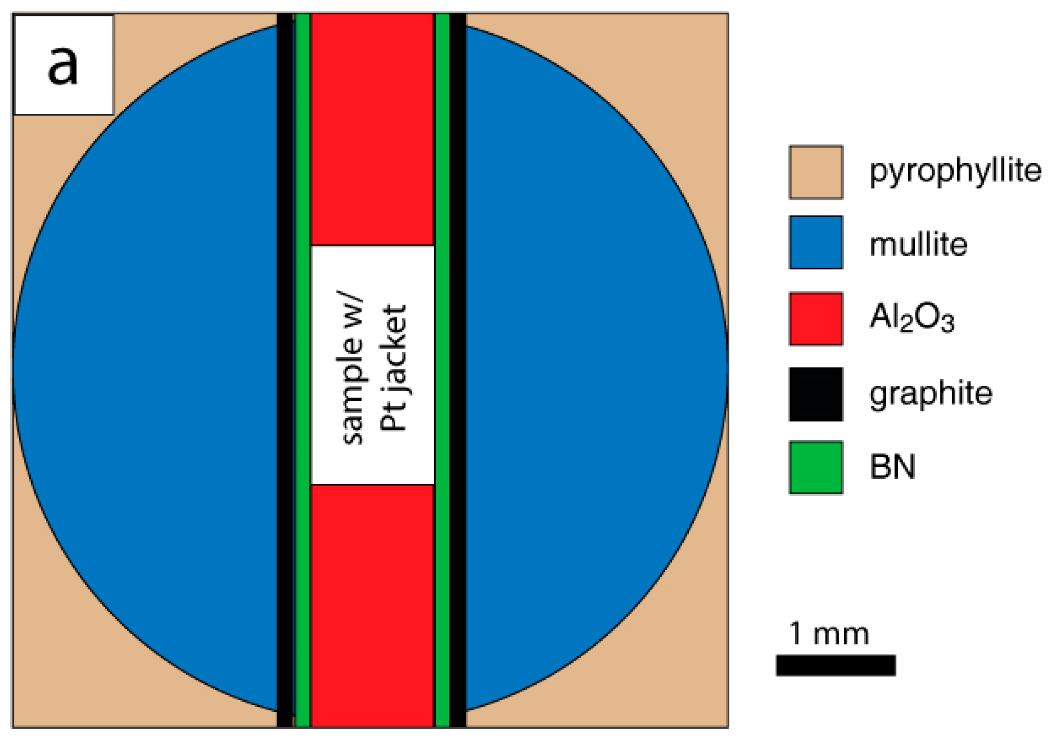
2.2.1. D-DIA Apparatus

Experiments on fine- and coarse-grained magnesite were performed using the D-DIA at beamline 6-BMB at the Advanced Photon Source at Argonne National Laboratory (Lemont, IL, USA). We used a modified Durham-type assembly [40] which consists of hollow cylinders of boron nitrate (BN) and graphite within a sphere of mullite in a soft-fired pyrophyllite cradle (Figure 1a). This assembly can accommodate a cylinder (or stacked cylinders) 1 mm diameter by 2 mm long, with crushable Al2O3 pistons at each end of the cylinders.
In the D-DIA experiments on fine-grained magnesite (Figure 1a; Table 2), a cylinder of magnesite 1 mm in length was stacked in the same column (but separated by a Pt foil) with a cylinder of dolomite and shortened at 500 °C and 750 °C; both specimens were deformed simultaneously. The fine-grained dolomite cylinders in these experiments are not presented here and are analyzed elsewhere [46]. Because stacked cylinders are deformed in series, they are deformed at approximately the same differential stress but different strain rates and we only report fine-grained magnesite strain rates. In D-DIA experiments on coarse-grained magnesite (Figure 1a; Table 3) a cylinder of magnesite of 1 mm diameter and 2 mm in length was shortened at 900 °C. All cylinders were wrapped in a thin Pt jacket and capped on both ends by thin Pt disks and thin Re foils adjacent to an alumina piston. The Pt jacket mechanically seals at experimental pressure and temperature and contains the CO2 generated by reaction, which fixes the CO2 pressure.
Pressure was applied to the assembly by the D-DIA by pressing six anvils in a cubic arrangement towards the assembly [42]. Experimental temperatures were achieved and maintained by applying a controlled wattage to a graphite furnace. The temperature gradient in the assembly is estimated to be ~100 °C/mm near the center of the assembly [47]. The temperature uncertainty with 1-mm long specimen is ±50 °C. Two vertically oriented tungsten carbide (WC) anvils are advanced towards the assembly to deform the column of crushable alumina and magnesite cylinders, while the horizontal anvils retract to maintain a constant cell volume and a constant pressure.

2.2.2. D-DIA Strain, Strain Rate and Stress Calculation

X-ray radiographs and spectra were collected during each experiment in order to determine strain and stress, respectively. All X-ray radiographs and spectra used in this study are archived as Supplementary Materials. X-ray radiographs of the magnesite cylinder and portions of the Al2O3 pistons were collected periodically during each experiment (Figure 3). Strain measurements were determined by measuring changes in relative position of the Re foils placed at the ends of magnesite cylinders, which appear as dark lines in X-ray radiographs. Strain rate was calculated from changes in strain as a function of time and X-ray diffraction spectra were collected from the Al2O3 pistons near the interface between the pistons and the magnesite during deformation to determine pressure and differential stresses. Elastic deformation of the grains in the Al2O3 pistons due to pressurization and axial loading causes changes in the lattice plane spacing (lattice strains) which are determined by measuring shifts of the X-ray diffraction peaks and knowing alumina elastic constants. (104), (110), (113), (024) and (116) peaks were used together with the PLOT85, Python and PolydefixED software [48,49]. The differential stress values calculated for all lattice planes at given time fall within ±− 0.2 GPa of the average differential stress reported here (Figure 4; Table 2 and Table 3).
A gradient was commonly observed in differential stress between top and bottom pistons at low strains, at the onset of each experiment (Figure 4a); at large strain (ε > 10%), however, this gradient usually decreases and both pistons experience similar stress conditions. When the stress gradient continued to be significant at later stages of the experiment, the last recorded stresses were averaged and the value (with large uncertainty) is reported in Table 2 and Table 3. Peak stresses that are observed before steady state deformation (i.e., when strain weakening occurred) are also reported but not used for extracting flow law parameters.

2.2.3. Griggs Apparatus

One experiment was performed on fine-grained magnesite using a solid salt assembly (SSA) at Peff = 0.76 GPa, ε · = 2.1 × 10⁻⁵ s−1 and T = 750 °C in the Griggs apparatus [50,51,52]. The stress resolution of the SSA (±0.03 GPa) [51] is considerably higher than that of the DDIA (see above). The SSA consists of concentric cylinders of NaCl, soft-fired pyrophyllite, and graphite that surround the Al2O3 pistons and magnesite cylinders (Figure 1b). The magnesite cylinder is jacketed by Ag with an Ag disc placed at each end of the jacket. The Ag jacket is crimped over the Ag discs (Figure 1b). The crimped ends of Ag jacket and discs create a mechanical weld at experimental conditions.
The SSA is resistively heated by a graphite furnace and temperature adjacent to the sample is monitored by a pre-manufactured K-type thermocouple with its welded bead positioned just outside the edge of the Ag jacket centered vertically along the axis of the magnesite cylinder. The temperature gradient is ~5–10 °C along the length of the magnesite cylinder [51]. The assembly is pressurized over a period of ~4 h before heating.
Loads are applied to samples in the Griggs apparatus by engaging a motor attached to a gear transmission which can advance a load ram into the pressure vessel at a constant rate. The load cell is located in the load column outside the sample assembly, which means the load measured includes friction at packings of the load piston, viscous flow in the sample assembly, and losses at other components of the load column. Therefore, the following correction was made to the mechanical data:
σcorr = 0.73 × σSSA − 0.048 GPa
where σcorr is the corrected stress, and σSSA is the stress calculated from force measurements [51]. This correction appears to be independent of pressure within the range of calibration experiments (P = 0.3–1.5 GPa, σSSA = 10–750 MPa, T = 600–1300 °C; [51,53,54]) and has been partially duplicated [55].

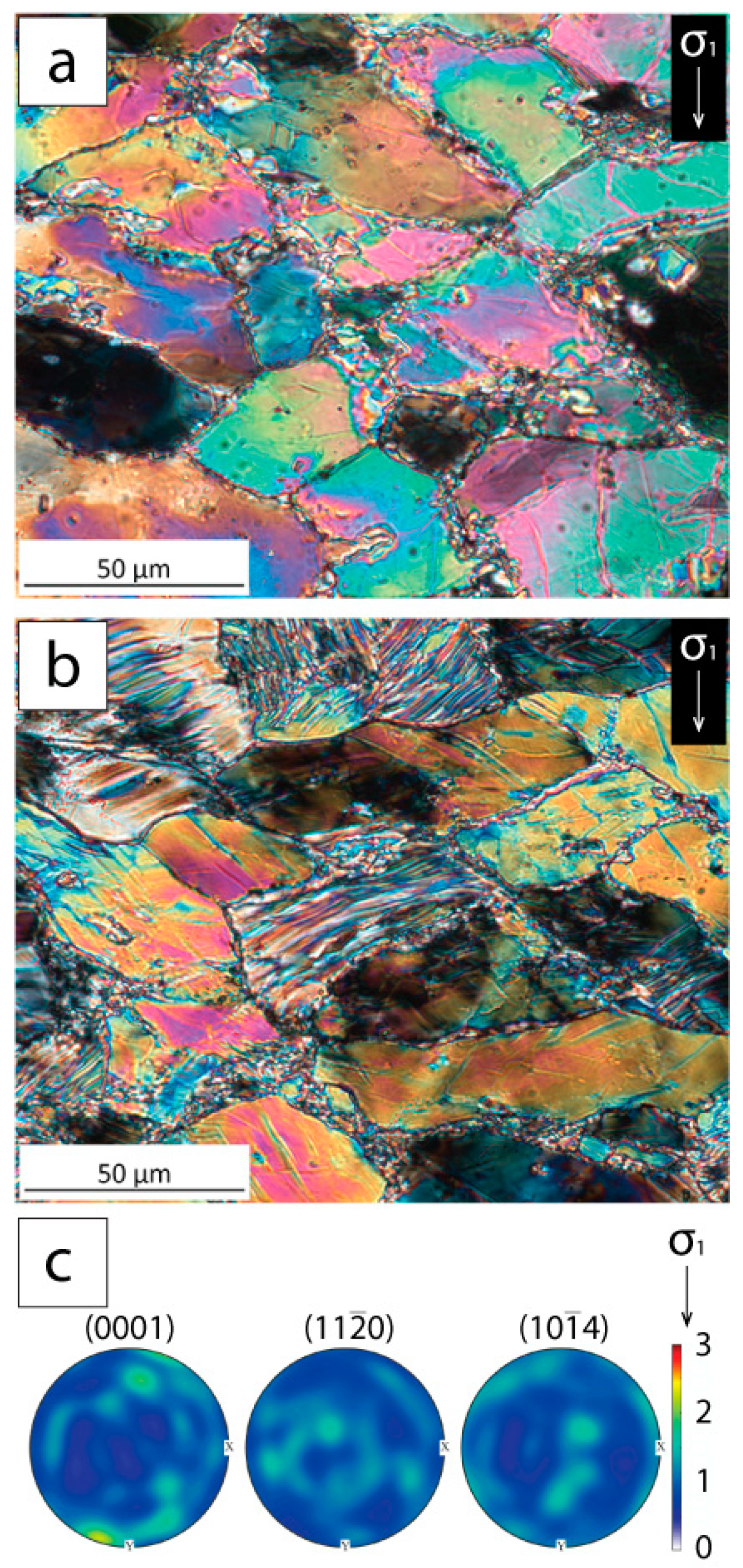
2.3. Microstructure and Texture Analyses

Upon reaching the desired strain for each experiment, samples were quenched and brought to room pressure over a period of 1–4 h. The magnesite cylinders were removed from the surrounding assembly materials and impregnated with epoxy and cut in half, parallel to the direction of compression. The cut faces of fine- and coarse-grained magnesite cylinders were ground using 3 µm alumina grit and polished with 0.3 µm Al2O3 powder. The cut cylinders were then cleaned in an ultrasonic cleaner and dried on a hot- plate overnight. Fine-grained magnesite samples were etched with dilute (0.1%) HCl for 1000 s to enhance grain boundaries and polished with colloidal silica for analysis in the scanning electron microscope using backscattered electron (BSE) imaging (using a FEI Quanta 200 located at the University of Akron). Grain orientations were determined by electron backscatter diffraction (EBSD) using a TESCAN LYRA-3 FESEM at the University of Akron and processed using MTEX. Pole figures were plotted and contoured using one point per grain. The number of grains measured is listed in the figure caption for each pole figure. Polished faces of coarse-grained magnesite samples were mounted to a glass slide, ground and polished with the same grits for the cut sample faces to a thickness of 2–10 µm, etched with colloidal silica and imaged using a Carl ZEISS Axio Scope A1 Microscope. Grain sizes and porosity of deformed samples were measured by tracing grains in Adobe Photoshop and determining equivalent diameters of grain tracings using Image SXM. Percentages of grains with kinks were determined by counting the total number of grains and the population of grains with kinks within that total.

3. Results

The pressure dependencies of magnesite deformation by LTP and diffusion creep were determined over effective pressures of 0.78–6.6 GPa from fine-grained magnesite experiments at T = 500 °C and 750 °C, respectively, and the pressure dependence of dislocation creep was determined over effective pressures of 2.9–7.5 GPa from coarse-grained magnesite experiments at T = 900 °C.

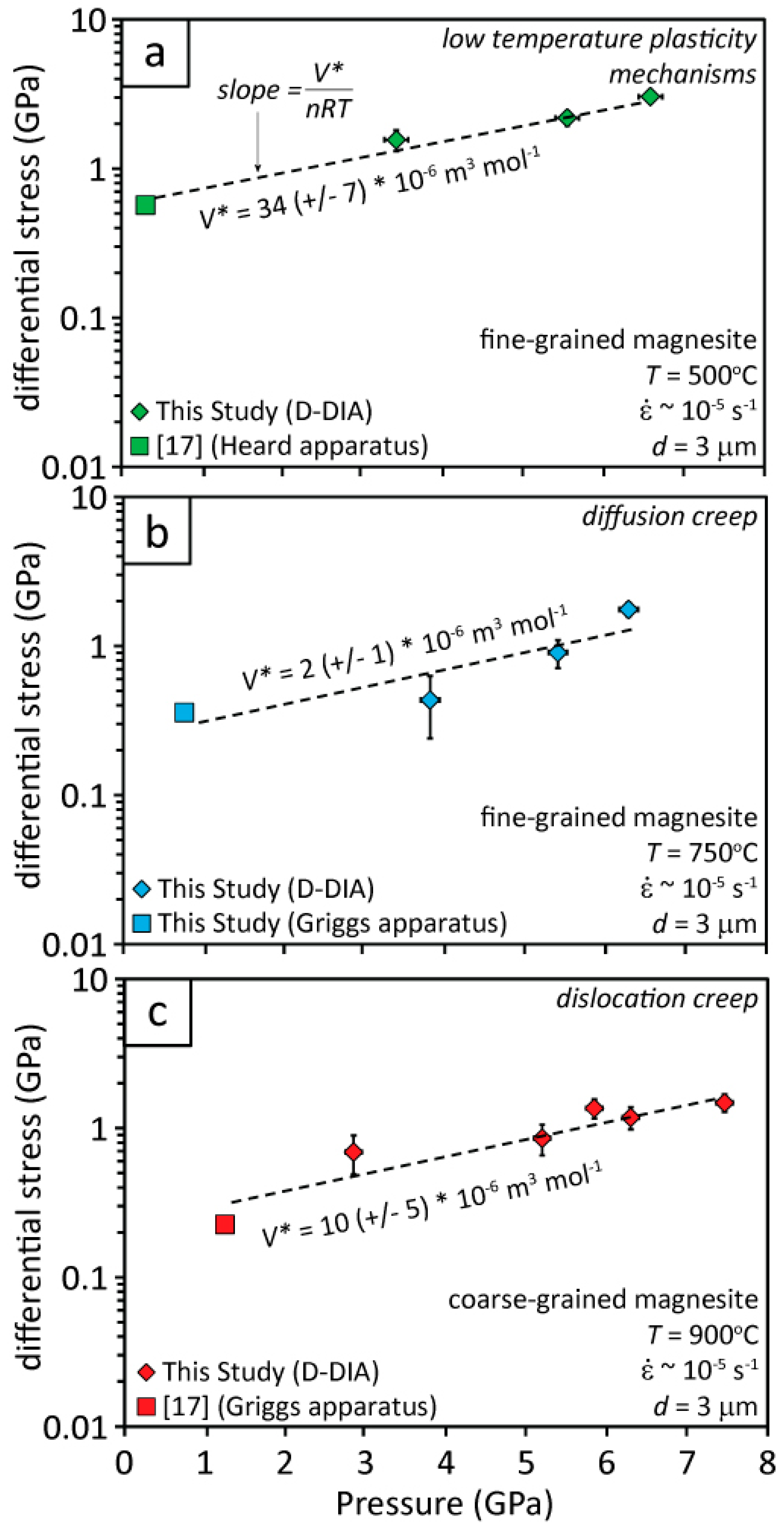
3.1. 500 °C Fine-Grained Magnesite Deformation

Fine-grained (d ~ 2 µm) magnesite cylinders were deformed at T = 500 °C, ε · = 2.5 – 2.8 × 10⁻⁵ s−1, and three pressures (Peff = 3.4, 5.6 and 6.6 GPa) to strains of 27, 28 and 27%, respectively (Table 1). In all experiments, differential stresses increased rapidly as the load rams were advanced and the magnesite cylinders yielded at ε ~ 6% (Figure 5a).
After yielding, differential stresses increased slowly until the end of each experiment. Differential stresses at the same temperature and strain rate increase with increasing pressure. All fine-grained magnesite cylinders deformed at T = 500 °C exhibit flattened grains that define foliation perpendicular to the compression direction. Kink bands are observed in some magnesite grains deformed at Peff = 6.6 GPa (Figure 6), but kink bands are not observed in magnesite grains deformed at lower pressures.
EBSD measurements of the orientations of grains of the magnesite deformed at Peff = 6.6 GPa to ε = 27% (MAG_004) reveal a weak [0001] point maxima parallel to the compression direction (Figure 6).

3.2. 750 °C Fine-Grained Magnesite Deformation

A pressure-stepping experiment was performed on a fine-grained (d ~ 2 µm) magnesite cylinder at three pressures (Peff = 6.3, 5.4, and 3.8 GPa) at T = 750 °C and ε · = 1.3–3.0 × 10⁻⁵·s−1 to strains of 6, 6, and 5%, respectively (Table 2). Results of this pressure-stepping experiment was supplemented by a deformation experiment performed in the Griggs apparatus at the same temperature and strain rate but much lower pressure, Peff = 0.76 GPa (Table 2). In all experiments, the differential stress increased rapidly as the load rams were advanced and the magnesite cylinders yielded at low strain (ε ~ 3%) (Figure 5b). After yielding, differential stress decreases slightly until the end of each experiment. The combined results following yielding reveal an increase in flow strength with pressure.
Microstructures observed in fine-grained magnesite deformed at T = 750 °C include rounded grains, greater porosity (~5%) than the starting material (<1%), and four-grain junctions (Figure 7). EBSD measurements of the orientations of magnesite grains in the magnesite cylinder deformed at T = 750 °C, ε · = 2.1 × 10⁻⁵·s−1 and Peff = 0.76 GPa to ε = 15% (Z-100) indicate little or no preferred orientation developed during deformation (Figure 7).

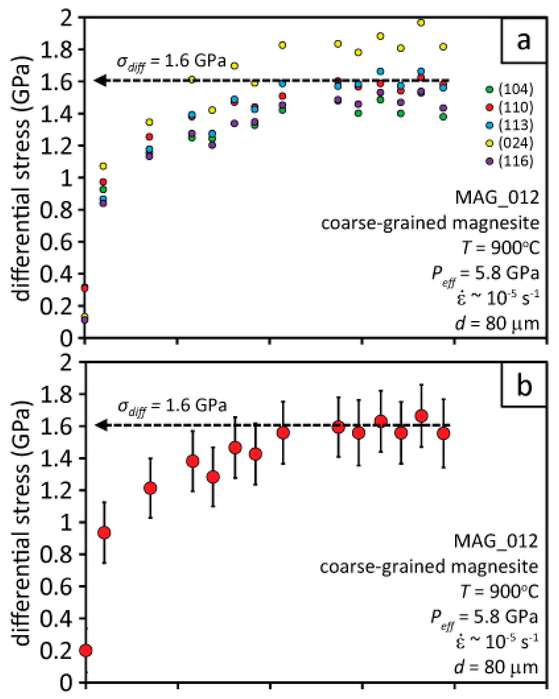
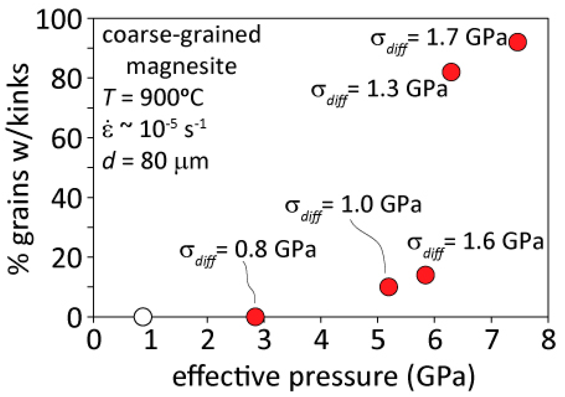
3.3. 900 °C Coarse-Grained Magnesite Deformation

Coarse-grained (d ~ 80 µm) magnesite cylinders were deformed at T = 900 °C, ε · = 2.9–3.5 × 10⁻⁵·s−1, and four pressures (Peff = 2.9, 5.2, 5.8, 6.3, and 7.5 GPa) in the D-DIA apparatus to strains of 36, 30, 30, 27, and 36%, respectively (Table 3). In all experiments, differential stress increased rapidly as the load rams were advanced and the magnesite yielded at low strains (ε ~ 3%) (Figure 5c). After yielding, differential stresses increased slowly until ε ~ 15% and reached a constant value at higher strains until the end of the experiment.
The coarse-grained magnesite cylinders deformed at T = 900 °C exhibit flattened grains that define foliation perpendicular to compression, undulatory extinction, and fine recrystallized grains at the original boundaries of coarse grains (Figure 8a). Kink bands are observed in porphyroclasts (Figure 8b) in all but the lowest pressure sample (MAG_014). The fraction of grains with kinks increases as a function of pressure, with a very sharp increase in the percentage of grains with kink bands at Peff > 6 GPa (Figure 9). EBSD measurements of the orientations of magnesite grain orientations of the sample deformed at Peff = 7.9 GPa to ε = 36% (MAG_010) indicate a weak [0001] axis point maximum parallel to the compression direction (Figure 8c).

4. Discussion

The mechanical and microstructural data of experiments performed on magnesite over a range of effective pressures (2.9–7.5 GPa) are consistent with deformation by low temperature plasticity mechanisms (T = 500 °C), diffusion creep (T = 750 °C for fine grained magnesite) or dislocation creep (T = 900 °C for coarse grained magnesite) as reported in [17].

4.1. Deformation of Fine-Grained Magnesite at 500 °C

Strengths of fine-grained magnesite deformed at T = 500 °C increase with increasing pressure and are greater than those of magnesite deformed at T = 750 °C and 900 °C (Figure 5). The flattened grains, lattice preferred orientations of these samples, along with high densities of tangled dislocations observed by [17] reflect low temperature plasticity (LTP) in the absence of diffusive recovery mechanisms. The evidence for this field of deformation in magnesite is comparable to observations of dislocation glide and crystal plasticity of calcite [56,57] and dolomite [58]. References [57] and [58] observed work hardening and flattening of grains perpendicular to the compression direction in calcite and dolomite aggregates, respectively. However, we have not observed mechanical twins in the deformed magnesite aggregates as observed in dolomite or found in abundance in calcite.

4.2. Deformation of Fine-Grained Magnesite at 750 °C

Strengths of fine-grained magnesite deformed at T = 750 °C are lower than those of fine-grained magnesite deformed at T = 500 °C, but they also increase with increasing pressure (Figure 5). The mechanical behavior and microstructures of these magnesite samples are consistent with those observed for fine-grained magnesite deformed by diffusion creep [17], similar to diffusion creep and grain boundary sliding of other carbonates [58,59,60].

4.3. Deformation of Coarse-grained Magnesite at 900 °C

Strengths of coarse-grained magnesite deformed at T = 900 °C are intermediate to those of fine-grained magnesite deformed by LTP and diffusion creep at T = 500 °C and 750 °C, respectively. Differential stresses similarly increase with increasing pressure (Figure 5). The mechanical behavior, flattened grains, undulatory extinction, and recrystallization at grain boundaries (Figure 8 and Figure 9) are similar to prior observations of dislocation creep [17]. The microstructures observed in these magnesite samples are similar to those of coarse-grained calcite marble [60,61] and dolomite [54,58] deformed by dislocation creep.

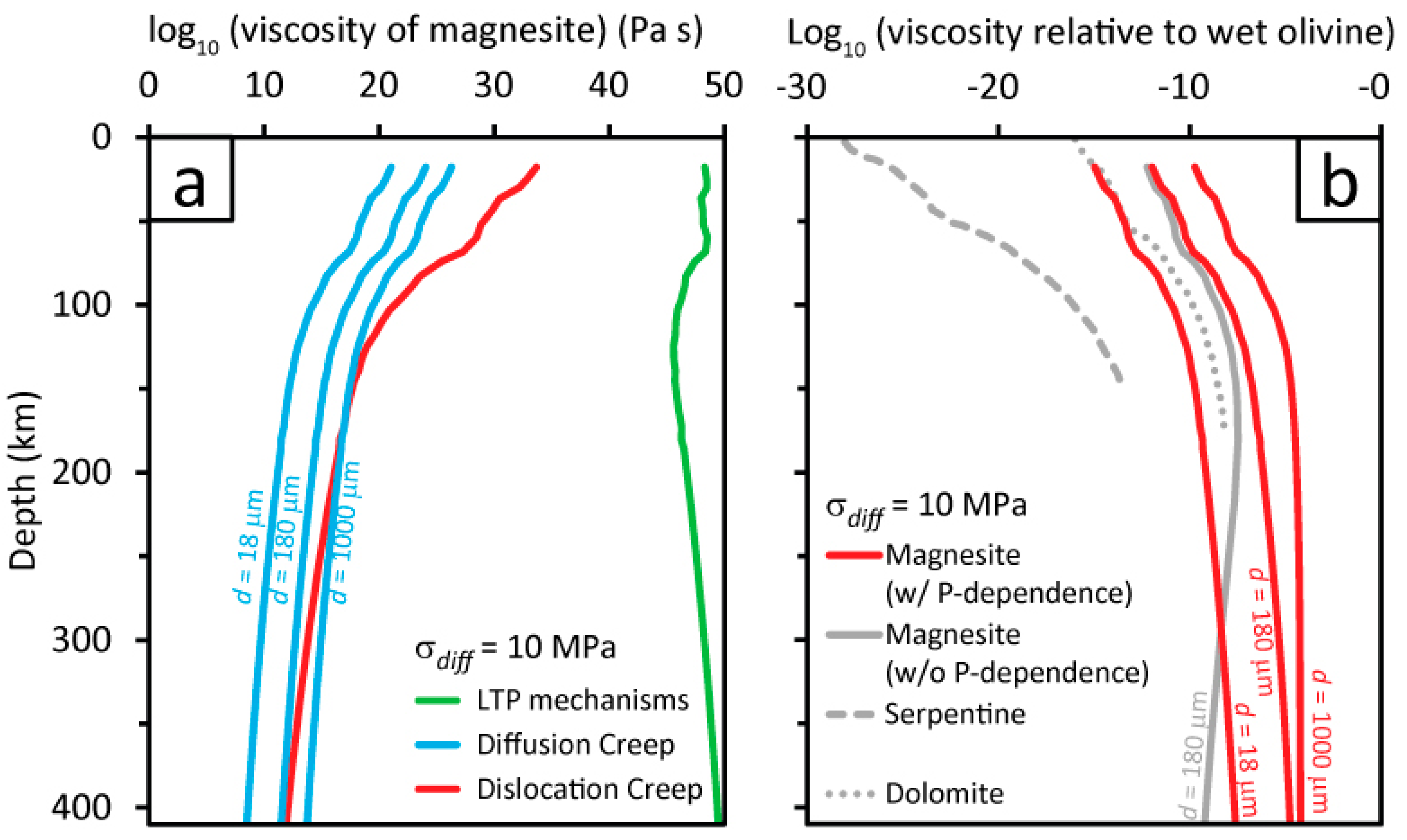
4.4. The effect of Pressure on Magnesite Deformation Mechanisms

In order to determine the pressure dependence of the strength of magnesite as characterized by the activation volume (V*) for the deformation processes LTP and dislocation creep, we combined our experimental data with two experiments from [17] performed on magnesite aggregates at lower pressures than applied in the present data for LTP and dislocation creep. The coarse-grained magnesite starting material of this study is the same as used by [17]. We acknowledge that the fine-grained magnesite used by [17] has a higher Ca concentration (Mg0.974Ca0.025Fe0.001CO3) than the fine-grained magnesite used in this study (Mg0.996Ca0.004CO3) and we do not know whether variations in Ca:Mg ratios of this magnitude affect deformation significantly. Given that grain sizes of the fine-grained magnesite used in this study and in [17] differ, we did not compare our results at high pressures with the lower pressure results of [17] for diffusion creep. Instead, we compared the high pressure results of this study for diffusion creep with new, lower pressure results (Z-100, T = 750 °C, ε · = 2.1 × 10⁻⁵ s−1, Peff = 0.76 GPa and ε = 15%) obtained using the Griggs apparatus, using the same fine-grained starting material (Table 1).
Strengths of all magnesite aggregates deformed at T = 500, 750 or 900 °C (at ε · over ~ 1.3–3.5 × 10⁻⁵ s−1) were normalized to the same strain rate ( ε · ~ 1.0 × 10⁻⁵ s−1) using the flow laws for magnesite aggregates deformed by LTP mechanisms, diffusion creep or dislocation creep reported by [17]. Given that thermally activated creep depends on an activation enthalpy, the creep strength at a given strain rate, temperature and grain size is expected to vary as:
ln(σ) = (V*/nRT)P
where σ is the differential stress (MPa), V* is the activation volume (m3·mol−1), n is the stress exponent, R is the universal gas constant (JK−1mol−1), T is temperature (K) and P is pressure (Pa). Our results, fitted to this relationship for LTP, diffusion creep and dislocation creep gives activation volumes (V*) of 34 (±7), 2 (±1) and 10 (±5) × 10−6 m3 mol−1, respectively (Table 4, Figure 10).
Given the values determined for V* from this study and the values of the stress exponent and activation enthalpies of [17], we recalculate the true activation energies for creep, and the pre-exponential (A) terms for the flow laws of each deformation mechanism by fitting to the flow law equation:
ε · = A σ n d m exp ( E * + P V * R T )
where A is a material constant (MPa−nµmms), n is the stress exponent, d is the grain size (µm), m is the grain size exponent, and E* is the apparent activation energy (J mol−1) (Table 4). In the following, we discuss the physical significance of our V* determinations in terms of deformation processes. We then compare the pressure dependence of magnesite deformation and the revised flow law with those of olivine to evaluate the relative strengths of magnesite and olivine along the P-T path of a subducting slab.

4.5. Physical Interpretations of V*

Of the activation volumes (V*) measured for deformation of magnesite, the largest is for low temperature plasticity, involving dislocation glide, the intermediate value is for dislocation creep, and the lowest value is for diffusion creep. Our value of V* for dislocation creep (10 × 10−6 m3 mol−1) is similar to the value of V* for dislocation creep of calcite (15 and 16.4 × 10⁻⁶ m3 mol−1) determined by [62], though smaller by ~34%, which appears to correlate to the smaller unit cell volume (23%) of magnesite compared with that of calcite. Our activation volume for dislocation creep of magnesite is large by comparison with molar volumes of cation point defects that might diffuse to and from dislocation jogs during dislocation climb and recovery, and compares favorably only with volumes expected for anion or compound defects, such as oxygen point defects (VO2 = 7 × 10⁻⁶ m3 mol−1) or defect pairs.
We might speculate that the pressure dependence of LTP is associated with volume changes during the formation of dislocation kinks, changes in dislocation core geometry, nucleation of double kinks or the molar volume of CO3 groups that must be rearranged along the slip plane. [63] infer that CO3 groups with large electrostatic valencies remain unbroken during slip of dolomite (and other carbonates) and the molar volume of CO3 (~25 × 10−6 m3 mol−1) is comparable to our measured value of V* (34 × 10−6 m3 mol−1) for LTP. By comparison the activation volume we measured for diffusion creep (V* = 2 × 10⁻⁶ m3 mol−1) is very small. This value may represent volume changes at grain boundaries that occur during grain boundary diffusion or sliding, with activated states that change volume little from original ground states of more disordered atomic structures between grains. Our measured V* for diffusion creep is large by comparison with molar volumes of Mg defects (VMg2+ = 0.7 × 10⁻⁶ m3 mol−1), but small by comparison with oxygen defects (VO2 = 7 × 10⁻⁶ m3 mol−1).

4.6. Application to Nature

Magnesite can form interconnected networks of veins [31] when carbonaceous fluids react with peridotite [32] in a subducting oceanic slab and magnesite remains stable into the deep mantle [22,35,36,37,38,39,64]. Reference [17] calculated the effective viscosity of magnesite, serpentine and dolomite relative to wet olivine along the pressure-temperature path of a subducting slab after [65] and found that magnesite was 7–9 orders of magnitude weaker than wet olivine deforming by dislocation creep along the entire subduction path. They speculated that strain could localize in magnesite aggregates at depths greater than ~175 km when all serpentine was no longer stable and that this strain localization may cause deep focus earthquakes. More recent modeling by [18] indicates that magnesite may cause nucleation of deep focus earthquakes along segments of subducting lithosphere where other mechanisms cannot operate.
We have used our revised flow laws for LTP mechanisms, diffusion creep and dislocation creep of magnesite aggregates to calculate the viscosity of each magnesite deformation mechanism in a subducting slab assuming: (1) the temperature-pressure path determined by [65] and (2) a differential stress of 0.01 GPa along the entire length of the subducting slab (Figure 10). Diffusion creep is the dominant deformation mechanism along the entire subduction path if the grain size is equal to or less than the recrystallized grain size predicted by the Twiss [66] recrystallized grain size-stress piezometer (d = 180 µm) for a differential stress of 0.01 GPa (Figure 11a). However, if the grain size is coarser than 180 µm, dislocation creep may become the dominant mechanism (Figure 11a).
The model of [17] using the same P-T path of [65] predicts that magnesite (with d = 180 µm) will be 7–9 orders of magnitude weaker than olivine from 200–400 km depth, respectively, in a subducting slab (Figure 11b). [17] also found that serpentine and dolomite were weaker than magnesite at shallower depths and speculated that strain may localize in zones of these minerals rather than magnesite at these shallower depths (Figure 11b). Recalculating the effective viscosity of magnesite relative to wet olivine [67] incorporating the pressure dependence of the strength of magnesite, the viscosity of magnesite relative to that of wet olivine decreases from 7–9 orders to 6–5 orders of magnitude lower at depths of 200–400 km, respectively. If grain sizes are <1000 µm, the viscosity contrast between olivine and magnesite decreases at a constant rate between 180–400 km depth. However, if magnesite grain size is ≥1000 µm, the viscosity contrast between magnesite and olivine (~5 orders of magnitude) remains constant over the same range of depths because dislocation creep, which is grain size insensitive, becomes the dominant deformation mechanism in magnesite aggregates. While the strength contrast is somewhat smaller when activation volumes are considered, the hypothesis that strain will localize in magnesite of weathered slabs by [17] continues to hold.
Intermediate depth deep focus earthquakes are observed in some subducting plates, such as the Tonga and parts of the Mariana subduction zones, but not in others, such as those in the Mariana, Chile, Izu-Bonin and Banda subduction zones [14]. Likewise, magnesite may form networks in some lithospheric slabs while it may be absent from others. Earthquakes in subducting plates that are seismically active from the surface to the lower mantle transition may be caused by the presence of interconnected magnesite with strain localization leading to creep instabilities, whereas plates without intermediate depth seismicity may contain little magnesite.

5. Conclusions

Triaxial deformation experiments performed on fine- and coarse-grained Nevada magnesite aggregates in D-DIA and Griggs apparatus at Peff = 0.76–7.5 GPa at T = 500, 750, or 900 °C at ~1.6 × 10⁻⁵·s−1 reveal pressure dependencies of flow strengths governed by LTP, diffusion creep and dislocation creep. At T = 500 °C and Peff = 3.4–6.6 GPa, fine-grained magnesite deforms by LTP mechanisms and shows a strong pressure dependence. At T = 750 °C and Peff = 0.76–6.3 GPa, fine-grained magnesite deforms by diffusion creep with very little pressure dependence. At T = 900 °C and Peff = 2.9–7.5 GPa, coarse-grained magnesite deforms by dislocation creep and has a pressure dependence similar to olivine (and to calcite) deforming by dislocation creep. The following conclusions are made:
  • The activation volumes calculated for LTP, diffusion creep, and dislocation creep of magnesite are V* = 34 (±7), 2 (±1), and 10 (±5) × 10−6·m−3·mol−1, respectively.
  • The effective viscosity of magnesite is 5–6 orders of magnitude lower than that of wet olivine in subducting slabs, when the pressure dependence is considered.
  • Strain may localize within magnesite horizons in subducting slabs resulting in intermediate depth deep focus earthquakes.

Supplementary Materials

All X-ray radiographs and spectra used in this study are available online at https://www.mdpi.com/2076-3263/9/10/420/s1, Title: manuscript-supplementary.zip.

Author Contributions

Conceptualization, C.W.H., A.K.K. and P.R.; methodology, C.W.H., A.K.K., P.R. and J.W.M.; software, J.W.M., C.A.M., C.B. (Casey Braccia), N.J., C.B. (Cole Blasko) and R.K.W.; validation, C.W.H., A.K.K., P.R.; formal analysis, J.M, C.B. (Casey Braccia), N.J., C.B. (Cole Blasko), R.K.W., C.W.H., A.K.K., and P.R.; investigation, J.M, C.B. (Casey Braccia), N.J., C.W.H., A.K.K., P.R. and L.T.; resources, C.W.H.; data curation, C.W.H., J.M. and C.B. (Cole Blasko); writing – original draft preparation, J.M. and C.W.H.; writing – review and editing, J.M, C.B. (Casey Braccia), N.J., C.B. (Cole Blasko), R.K.W., C.A.M., C.W.H., A.K.K., P.R. and L.T.; visualization, J.M., C.W.H., C.B. (Cole Blasko), and R.K.W.; supervision, C.W.H., A.K.K. and P.R.; project administration, C.W.H., A.K.K. and P.R.; funding acquisition, C.W.H., A.K.K. and P.R.;

Funding

J.W.M. and C.A.M. were supported by teaching assistantships from the University of Akron and research assistantships from NSF grant EAR-1624242 to C.W.H. This NSF grant also provided salary and research support to R.W., C.B. (Casey Braccia), N.J. and C.W.H. Research activities by A.K.K. and P.R. were supported by NSF grants EAR-1624249 and EAR-1623788, respectively. The APS 6BM-B Beamline is supported by COMPRES, the Consortium for Materials Properties Research in Earth Sciences under NSF Cooperative Agreement EAR-1661511. This research used resources of the Advanced Photon Source, a U.S. Department of Energy (DOE) Office of Science User Facility operated for the DOE Office of Science by Argonne National Laboratory under Contract No. DE-AC02-06CH11357.

Acknowledgments

We would like to thank Haiyan Chen for all her help at the APS 6BM-B Beamline. J.M., C.A.M., C.B. (Casey Braccia) and N.J. would like to thank the University of Akron Department of Geosciences for providing partial funding to present results of these experiments. Part of the work was carried out while P.R. was serving at the National Science Foundation (NSF). Any opinion, findings, and conclusions or recommendations expressed in this material are those of the authors and do not necessarily reflect the views of the NSF.

Conflicts of Interest

The authors declare no conflict of interest.

References

  1. Green, H.W.; Houston, H. The mechanics of deep earthquakes. Annu. Rev. Earth Plant. Sci. 1995, 23, 169–213. [Google Scholar] [CrossRef]
  2. Bilek, S.L.; Lay, T. Subduction Zone Megathrust Earthquakes. Geosphere 2018, 14, 1468–1500. [Google Scholar] [CrossRef]
  3. Wadati, K. Shallow and deep earthquakes. Geophys. Mag. 1928, 1, 162–202. [Google Scholar]
  4. Hacker, B.R.; Peacock, S.M.; Abers, G.A.; Holloway, S.D. Subduction factory-2. Are intermediate-depth earthquakes in subducting slabs linked to metamorphic dehydration reactions? J. Geophys. Res. Sol. Earth 2003, 108. [Google Scholar] [CrossRef]
  5. Hilairet, N.; Reynard, B.; Wang, Y.B.; Daniel, I.; Merkel, S.; Nishiyama, N.; Petitgirard, S. High-pressure creep of serpentine, interseismic deformation, and initiation of subduction. Science 2007, 318, 1910–1913. [Google Scholar] [CrossRef] [PubMed]
  6. Peacock, S.M. Are the lower planes of double seismic zones caused by serpentine dehydration in subducting oceanic mantle? Geology 2001, 29, 299–302. [Google Scholar] [CrossRef]
  7. Raleigh, C.B.; Paterson, M.S. Experimental deformation of serpentinite and its tectonic implications. J. Geophys. Res. 1965, 70, 3965–3985. [Google Scholar] [CrossRef]
  8. Ulmer, P.; Trommsdorff, V. Serpentine stability to mantle depths and subduction-related magmatism. Science 1995, 268, 858–861. [Google Scholar] [CrossRef]
  9. Burnley, P.; Green, D.H.; Prior, D. Faulting associated with the olivine to spinel transformation in Mg2GeO4 and its implications for deep-focus earthquake. J. Geophys. Res. 1991, 96, 425–443. [Google Scholar] [CrossRef]
  10. Kirby, S.H.; Stein, S.; Okal, E.A.; Rubie, D.C. Metastable mantle phase transformations and deep earthquakes in subducting oceanic lithosphere. Rev. Geophys. 1996, 34, 261–306. [Google Scholar] [CrossRef]
  11. Schubnel, A.; Brunet, F.; Hilairet, N.; Gasc, J.; Wang, Y.B.; Green, H.W. Deep-focus earthquake analogs recorded at high pressure and temperature in the laboratory. Science 2013, 341, 1377–1380. [Google Scholar] [CrossRef] [PubMed]
  12. Flinn, E.A.; Engdahl, E.R. A proposed basis for geographical and seismic regionalization. Rev. Geophys. 1965, 3, 123–149. [Google Scholar] [CrossRef]
  13. Frohlich, C. Deep Earthquakes; Cambridge University Press: Cambridge, UK, 2006. [Google Scholar]
  14. Karato, S.; Riedel, M.R.; Yuen, D.A. Rheological structure and deformation of subducted slabs in the mantle transition zone: Implications for mantle circulation and deep earthquakes. Phys. Earth Planet. Inter. 2001, 127, 83–108. [Google Scholar] [CrossRef]
  15. Griggs, D.T.; Baker, D.W. The origin of deep-focus earthquakes. In Properties of Matter under Unusual Conditionss (in Honor of Edward Teller’s 60th Birthday); Mark, H., Fernbach, S., Eds.; Interscience Publishers: New York, NY, USA; London, UK, 1969; pp. 23–42. [Google Scholar]
  16. Kelemen, P.B.; Hirth, G. A periodic shear-heating mechanism for intermediate-depth earthquakes in the mantle. Nature 2007, 446, 787–790. [Google Scholar] [CrossRef] [PubMed]
  17. Holyoke, C.W.I.; Kronenberg, A.K.; Newman, J.; Ulrich, C. Rheology of magnesite. J. Geophys. Res. 2014, 119, 1–24. [Google Scholar] [CrossRef]
  18. Li, J.; Zheng, Y.; Thomsen, T.; Lapen, T.; Fang, X. Deep earthquakes in subducting slabs hosted in highly anisotropic rock fabric. Nat. Geosci. 2018, 11, 696–700. [Google Scholar] [CrossRef]
  19. Dasgupta, R.; Hirschmann, M.M. The deep carbon cycle and melting in Earth’s interior. Earth Planet. Sci. Lett. 2010, 298, 1–13. [Google Scholar] [CrossRef]
  20. Ducea, M.N.; Saleeby, J.; Morrison, J.; Valencia, V.A. Subducted carbonates, metasomatism of mantle wedges, and possible connections to diamond formation: An example from California. Am. Mineral. 2005, 90, 864–870. [Google Scholar] [CrossRef]
  21. Goto, A.; Kunugiza, K.; Omori, S. Evolving fluid composition during prograde metamorphism in subduction zones: A new approach using carbonate-bearing assemblages in the pelitic system. Gondwana Res. 2007, 11, 166–179. [Google Scholar] [CrossRef]
  22. Isshiki, M.; Irifune, T.; Hirose, K.; Ono, S.; Ohishi, Y.; Watanuki, T.; Nishibori, E.; Takata, M.; Sakata, M. Stability of magnesite and its high-pressure form in the lowermost mantle. Nature 2004, 427, 60–63. [Google Scholar] [CrossRef]
  23. Kerrick, D.M.; Connolly, J.A.D. Metamorphic devolatilization of subducted oceanic metabasalts: Implications for seismicity, arc magmatism and volatile recycling. Earth Planet. Sci. Lett. 2001, 189, 19–29. [Google Scholar] [CrossRef]
  24. Kilian, R.; Behrmann, J.H. Geochemical constraints on the sources of Southern Chile Trench sediments and their recycling in arc magmas of the Southern Andes. J. Geol. Soc. Lond. 2003, 160, 57–70. [Google Scholar] [CrossRef] [Green Version]
  25. Plank, T.; Langmuir, C.H. The chemical composition of subducting sediment and its consequences for the crust and mantle. Chem. Geol. 1998, 145, 325–394. [Google Scholar] [CrossRef]
  26. Rea, D.K.; Ruff, L.J. Composition and mass flux of sediment entering the world’s subduction zones: Implications for global sediment budgets, great earthquakes, and volcanism. Earth Planet. Sci. Lett. 1996, 140, 1–12. [Google Scholar] [CrossRef]
  27. Sleep, N.H.; Zahnle, K. Carbon dioxide cycling and implications for climate on ancient Earth. J. Geophys. Res. 2001, 106, 1373–1399. [Google Scholar] [CrossRef]
  28. Snyder, G.; Poreda, R.; Hunt, A.; Fehn, U. Regional variations in volatile composition: Isotopic evidence for carbonate recycling in the Central American volcanic arc. Geochem. Geophys. Geosyst. 2001, 2. [Google Scholar] [CrossRef]
  29. Zhang, L.; Ellis, D.J.; Arculus, R.J.; Jiang, W.; Wei, C. ‘Forbidden zone’ subduction of sediments to 150 km depth—The reaction of dolomite to magnesite plus aragonite in the UHPM metapelites from western Tianshan, China. J. Metamorph. Geol. 2003, 21, 523–529. [Google Scholar] [CrossRef]
  30. Kelemen, P.B.; Matter, J.; Streit, E.E.; Rudge, J.F.; Curry, W.B.; Blusztajn, J. Rates and mechanisms of mineral carbonation in peridotite: Natural processes and recipes for enhanced, in situ CO2 capture and storage. Annu. Rev. Earth Plant. Sci. 2011, 39, 545–576. [Google Scholar] [CrossRef]
  31. Quesnel, B.; Gautier, P.; Boulvais, P.; Cathelineau, M.; Maurizot, P.; Cluzel, D.; Ulrich, M.; Guillot, S.; Lesimple, S.; Couteau, C. Syn-tectonic, meteoric water-derived carbonation of the New Caledonia peridotite nappe. Geology 2013, 41, 1063–1066. [Google Scholar] [CrossRef]
  32. Saldi, G.D.; Jordan, G.; Schott, J.; Oelkers, E.H. Magnesite growth rates as a function of temperature and saturation state. Geochim. Cosmochim. Acta 2009, 73, 5646–5657. [Google Scholar] [CrossRef]
  33. Seto, Y.; Hamane, D.; Nagai, T.; Fujino, K. Fate of carbonates within oceanic plates subducted to the lower mantle, and a possible mechanism of diamond formation. Phys. Chem. Miner. 2008, 35, 223–229. [Google Scholar] [CrossRef]
  34. Kelemen, P.B.; Hirth, G. Reaction-driven cracking during retrograde metamorphism: Olivine hydration and carbonation. Earth Planet. Sci. Lett. 2012, 345, 81–89. [Google Scholar] [CrossRef]
  35. Biellmann, C.; Gillet, P.; Guyot, F.; Peyronneau, J.; Reynard, B. Experimental-evidence for carbonate stability in the Earths lower mantle. Earth Planet. Sci. Lett. 1993, 118, 31–41. [Google Scholar] [CrossRef]
  36. Brey, G.; Brice, W.R.; Ellis, D.J.; Green, D.H.; Harris, K.L.; Ryabchikov, I.D. Pyroxene-carbonate reactions in the upper mantle. Earth Planet. Sci. Lett. 1983, 62, 63–74. [Google Scholar] [CrossRef]
  37. Canil, D.; Scarfe, C.M. Phase-relations in peridotite + CO2 systems to 12 GPa-Implications for the origin of kimberlite and carbonate stability in the Earths upper mantle. J. Geophys. Res. 1990, 95, 15805–15816. [Google Scholar] [CrossRef]
  38. Katsura, T.; Ito, E. Melting and subsolidus phase-relations in the MgSiO3-MgCO3 system at high-pressures - Implications to evolution of the Earths atmosphere. Earth Planet. Sci. Lett. 1990, 99, 110–117. [Google Scholar] [CrossRef]
  39. Newton, R.C.; Sharp, W.E. Stability of forsterite + CO2 and its bearing on role of CO2 in mantle. Earth Planet. Sci. Lett. 1975, 26, 239–244. [Google Scholar] [CrossRef]
  40. Durham, W.B.; Mei, S.; Kohlstedt, D.L.; Wang, L.; Dixon, N.A. New measurements of activation volume in olivine under anhydrous conditions. Phys. Earth Planet. Inter. 2009, 172, 67–73. [Google Scholar] [CrossRef]
  41. Raterron, P.; Amiguet, E.; Chen, J.H.; Li, L.; Cordier, P. Experimental deformation of olivine single crystals at mantle pressures and temperatures. Phys. Earth Planet. Inter. 2009, 172, 74–83. [Google Scholar] [CrossRef] [Green Version]
  42. Wang, Y.; Durham, W.B.; Getting, I.C.; Weidner, D.J. The deformation-DIA: A new apparatus for high-temperature triaxial deformation to pressures up to 15 GPa. Rev. Sci. Instrum. 2003, 74, 3002–3011. [Google Scholar] [CrossRef]
  43. Goldsmith, J.R.; Heard, H.C. Subsolidus phase relations in the system CaCO3-MgCO3. J. Geol. 1961, 69, 45–74. [Google Scholar] [CrossRef]
  44. Harker, R.I.; Tuttle, O.F. Studies in the system CaO-MgO-CO2; Part 2, Limits of solid solution along the binary join CaCO3-MgCO3. Am. J. Sci. 1955, 253, 274–282. [Google Scholar] [CrossRef]
  45. Irving, A.J.; Wyllie, P.J. Subsolidus and Melting Relationships for Calcite, Magnesite and Join Caco3-Mgco3 to 36 Kb. Geochim. Cosmochim. Acta 1975, 39, 35–53. [Google Scholar] [CrossRef]
  46. Blasko, C. Pressure Dependence of Polycrystalline Magnesite and Dolomite; University of Akron: Akron, OH, USA, 2017. [Google Scholar]
  47. Raterron, P.; Holyoke, C.W.; Merkel, S. Temperature gradients and stress measurements in the deformation-DIA cell using alumina pistons. Rev. Sci. Instrum. 2013, 84, 043906. [Google Scholar] [CrossRef] [PubMed]
  48. Girard, J.; Chen, J.H.; Raterron, P.; Holyoke, C. Deformation of single crystal sample using D-DIA apparatus coupled with synchrotron X-rays: In situ stress and strain measurements at high pressure and temperature. J. Phys. Chem. Solids 2010, 71, 1053–1058. [Google Scholar] [CrossRef]
  49. Merkel, S.; Hilairet, N. Multifit/Polydefix: A framework for the analysis of polycrystal deformation using X-rays. J. Appl. Crystallogr. 2015, 48, 1307–1313. [Google Scholar] [CrossRef]
  50. Griggs, D.T. Hydrolytic weakening of quartz and other silicates. Geophys. J. R. Astron. Soc. 1967, 14, 19–31. [Google Scholar] [CrossRef]
  51. Holyoke, C.W.; Kronenberg, A.K. Accurate differential stress measurement using the molten salt cell and solid salt assemblies in the Griggs apparatus with applications to strength, piezometers and rheology. Tectonophysics 2010, 494, 17–31. [Google Scholar] [CrossRef]
  52. Tullis, T.E.; Tullis, J. Experimental rock deformation techniques. In Mineral and Rock Deformation; Laboratory Studies; the Paterson Volume; American Geophysical Union: Washington, DC, USA, 1986; Volume 36, pp. 297–324. [Google Scholar]
  53. Barbery, A. The Effect of Water Content on the Strength of Quartzite. Master’s Thesis, University of Akron, Akron, OH, USA, 2017. [Google Scholar]
  54. Holyoke, C.W.; Newman, J.; Kronenberg, A.K. Dislocation creep of polycrystalline dolomite. Tectonophysics 2013, 590, 72–82. [Google Scholar] [CrossRef]
  55. Kido, M.; Muto, J.; Nagahama, H. Method for correction of differential stress calculations from experiments using the solid salt assembly in a Griggs-type deformation apparatus. Tectonophysics 2016, 672, 170–176. [Google Scholar] [CrossRef]
  56. Liu, J.; Walter, J.; Weber, K. Fluid-enhanced low-temperature plasticity of calcite marble: Microstructures and mechanisms. Geology 2002, 30, 787–790. [Google Scholar] [CrossRef]
  57. Rutter, E.H. Influence of temperature, strain rate and interstitial water in experimental deformation of calcite rocks. Tectonophysics 1974, 22, 311–334. [Google Scholar] [CrossRef]
  58. Davis, N.E.; Kronenberg, A.K.; Newman, J. Plasticity and diffusion creep of dolomite. Tectonophysics 2008, 456, 127–146. [Google Scholar] [CrossRef]
  59. Delle Piane, C.; Burlini, L.; Kunze, K.; Brack, P.; Burg, J.P. Rheology of dolomite: Large strain torsion experiments and natural examples. J. Struct. Geol. 2008, 30, 767–776. [Google Scholar] [CrossRef]
  60. Schmid, S.M.; Boland, J.N.; Paterson, M.S. Superplastic flow in finegrained limestone. Tectonophysics 1977, 43, 257–291. [Google Scholar] [CrossRef]
  61. Schmid, S.M.; Paterson, M.S.; Boland, J.N. High temperature flow and dynamic recrystallization in Carrara marble. Tectonophysics 1980, 65, 245–280. [Google Scholar] [CrossRef]
  62. De Bresser, J.H.P. On the mechanism of dislocation creep of calcite at high temperature: Inferences from experimentally measured pressure sensitivity and strain rate sensitivity of flow stress. J. Geophys. Res. 2002, 107. [Google Scholar] [CrossRef]
  63. Wenk, H.R.; Barber, D.J.; Reeder, R.J. Microstructures in carbonates. In Carbonates; Mineralogy and Chemistry; Mineralogical Society of America: Washington, DC, USA, 1983; Volume 11, pp. 301–367. [Google Scholar]
  64. Panero, W.R.; Kabbes, J.E. Mantle-wide sequestration of carbon in silicates and the structure of magnesite II. Geophys. Res. Lett. 2008, 35. [Google Scholar] [CrossRef]
  65. Peacock, S.M.; van Keken, P.E.; Holloway, S.D.; Hacker, B.R.; Abers, G.A.; Fergason, R.L. Thermal structure of the Costa Rica-Nicaragua subduction zone. Phys. Earth Planet. Inter. 2005, 149, 187–200. [Google Scholar] [CrossRef]
  66. Twiss, R.J. Theory and Applicability of a Recrystallized Grain-Size Paleopiezometer. Pure Appl. Geophys. 1977, 115, 227–244. [Google Scholar] [CrossRef]
  67. Hirth, G.; Kohlstedt, D. Rheology of the upper mantle and mantle wedge; a view from the experimentalists. In Inside the Subduction Factory; American Geophysical Union: Washington, DC, USA, 2003; Volume 138, pp. 83–105. [Google Scholar]
Figure 1. A modified Durham-type assembly [40] was used in all experiments performed using the D-DIA (a). A solid salt assembly was used in all experiments performed in the Griggs apparatus (b).
Geosciences 09 00420 g001aGeosciences 09 00420 g001b
Figure 2. A fine-grained (d ~ 2 µm; a - photomicrograph, b – SEM-BSE image) and coarse-grained (d ~ 80 µm; c – photomicrograph) natural magnesite aggregate from Nevada, USA were used in the experiments performed in this study. All cores were collected parallel to the NS axis of the lower hemisphere equal area nets (d). Both magnesite aggregates have no lattice preferred orientation (d; fine n = 1728; coarse n = 200; poles are contoured to the basal (0001), prism (11–20), and rhomb (10–14) planes).
Geosciences 09 00420 g002
Figure 3. Radiographs of samples collected in-situ were used to determine strain and strain rate during all experiments (MAG_012, T = 900 °C, Peff = 5.8 GPa, ε · = 3.3 × 10⁻⁵ s−1, σdiff = 1.6 GPa, (a) prior to deformation and (b) at ε = 30%). Measurements of sample length were collected from the interface between the magnesite cylinder and Re foils (dark lines, measurement location highlighted by white line). The darker grey area in the Al2O3 pistons is where the Pt jacket overlaps the Al2O3 pistons. The black areas to the sides of the load column are caused by the WC anvils that absorb X-rays and partially block the view of the magnesite cylinder and Al2O3 pistons, which are transparent to X-rays.
Geosciences 09 00420 g003
Figure 4. Peaks due to X-ray diffraction from five lattice planes in Al2O3 are used to calculate differential stresses (a) and pressure (not shown) during the as a function of time during the experiment. (b) The stresses from each lattice plane reflection are averaged to report a differential stress and the range of calculated stresses is listed as the error. (c) Strains determined over the same time interval are determined from X-radiographs (as shown in Figure 3) and used to determine the average strain rate. The data from (b) and (c) can be combined as a stress-strain plot and used to evaluate if the magnesite cylinders deformed at constant stress at the constant strain rate and larger values of strains (d).
Geosciences 09 00420 g004aGeosciences 09 00420 g004b
Figure 5. Strengths of fine-grained magnesite deformed at T = 500 °C (a) are greater than those of fine-grained magnesite deformed at T = 750 °C (b) and coarse-grained magnesite deformed at T = 900 °C (c). Fine-grained magnesite cylinders deformed at T = 500 °C strain harden during deformation (a) while the fine-grained magnesite cylinders deformed at T = 750 °C deform at relatively constant stresses or strain weaken (b). Coarse-grained magnesite cylinders deformed at T = 900 °C deform at relatively constant stresses (c). Strengths of magnesite cylinders in all sets increase as a function of increasing pressure.
Geosciences 09 00420 g005aGeosciences 09 00420 g005b
Figure 6. Microstructures in fine-grained magnesite cylinders deformed at T = 500 °C include flattened angular grains (arrows) and no twins or kinks (a, SEM BSE image; MAG_005, T = 500 °C, Peff = 3.4 GPa, ε · = 2.7 × 10⁻⁵ s−1, σdiff = 1.6 GPa). Kinks (dark bands) are observed only in grains in the fine-grained magnesite cylinder deformed at Peff = 6.6 GPa (b, SEM BSE image; MAG_004, T = 500 °C, Peff = 6.3 GPa, ε · = 2.7 × 10⁻⁵ s−11, σdiff = 3.1 GPa). The c-axes (equivalently poles to basal (0001) planes) form a weak point maxima parallel to the compression direction in the lower hemisphere equal area projection and a-axes (equivalently poles to (1120) planes) and poles to rhomb (10–14) planes do not show a clear pattern (c; n = 780).
Geosciences 09 00420 g006aGeosciences 09 00420 g006b
Figure 7. Microstructures in fine-grained magnesite cylinders deformed at T = 750 °C in the Griggs apparatus (a) and DDIA (b) include rounded grains and increased porosity relative to the starting material. (SEM BSE images; (a), Z-100, T = 750 °C, Peff = 0.76 GPa, = 2.1 × 10⁻⁵·s−1, σdiff = 0.38 GPa; (b), MAG_020, T = 750 °C, Peff = 6.3–3.8 GPa, ε · ~ 10−5·s−1, σdiff = 1.6 GPa). (c) EBSD measurements of poles to basal (0001), prism (11–20), and rhomb (10–14) planes indicate that no discernable LPO has developed in the samples deformed at T = 750 °C (Z-100, Peff = 0.76 GPa, ε · = 2.1 × 10⁻⁵·s−1, σdiff = 0.38 GPa, n = 1366).
Geosciences 09 00420 g007
Figure 8. Microstructures in coarse-grained magnesite cylinders deformed at T = 900 °C in the DDIA (a) include flattened relict grains, recrystallized grains at relict grain boundaries, undulatory extinction and few kinks (Photomicrograph, MAG_014, T = 900 °C, Peff = 2.9 GPa, ε · = 3.5 × 10⁻⁵·s−1, σdiff = 0.8 GPa). (b) At higher pressures (Peff > 6 GPa) most grains of deformed coarse magnesite areheavily kinked (photomicrograph, MAG_010, T = 900 °C, Peff = 7.5 GPa, ε · = 2.9 × 10⁻⁵·s−1, σdiff = 1.6 GPa). (c) c-axes (equivalently poles to (0001) axes) of recrystallized grains form a weak point maxima parallel to the compression direction in the lower hemisphere equal area projection and a-axes (equivalently the poles to (1120) prism planes) and poles to (10–14) rhomb planes show little to no preferred orientation (MAG_014, T = 900 °C, Peff = 7.5 GPa, ε · = 2.9 × 10⁻⁵·s−1, σdiff = 0.8 GPa, n = 1433).
Geosciences 09 00420 g008
Figure 9. Kinking is not observed in coarse-grained magnesite deformed at Peff < 3 GPa, but the percentage of grains with kinks increases slightly with increasing pressure from Peff = 3 to Peff ~ 6 GPa and dramatically increases at Peff > 6 GPa (red points, this study, D-DIA; open circle, [17], Griggs apparatus).
Geosciences 09 00420 g009
Figure 10. The strengths of magnesite aggregates deformed at T = 500 (a), 750 (b) and 900 °C (c) all increase as a function of increasing pressure. Activation volumes (V*) for magnesite deformed by LTP mechanisms, diffusion creep and dislocation creep are 34, 2 and 10 × 10−6 m3 mol−1.
Geosciences 09 00420 g010
Figure 11. The viscosity of magnesite along the P-T path of subducting oceanic lithosphere [after [65] is dominated by diffusion creep when grain sizes are <1000 µm, but dislocation creep becomes dominant at larger grain sizes (a). Recalculation of the magnesite flow laws of [17] to include the pressure dependence of the strengths of each deformation mechanism does not significantly change the implications of their model (b). The strength of magnesite is greater when pressure dependence is included, but magnesite is still at least five orders of magnitude weaker than wet olivine at all conditions along the P-T path of subducting oceanic lithosphere. Serpentine – [5]; Dolomite – [54,58]; Magnesite without pressure dependence – [17]; Magnesite with pressure dependence – this study; wet olivine – [67].
Geosciences 09 00420 g011
Table 1. Compositions of magnesite aggregates.
MagnesiteGrain SizePorosityMg 1CaMnFe
(µm)+\−n%
Nevada Coarse8016324<10.994+/−0.0050.004+/−0.003ND+/−0.0000.002+/−0.002
Nevada Fine20.6216<10.996+/−0.0010.004+/−0.001ND+/−0.000ND+/−0.000
1 - normalized to three oxygens (i.e., MgCO3).
Table 2. List of experiments performed on fine-grained Nevada magnesite.
ExperimentTemperaturePressureEffective PressureInitial Strain RateFinal Strain RateStrainPeak StrengthFinal StrengthGrain SizePorosity
(°C)(GPa)(GPa)(×10−5 s−1)(×10−5 s−1)(%)(GPa)(GPa)(µm)n%
MAG_005 ad5003.4 ± 0.13.4 ± 0.10.72.7271.6 ± 0.31.6 ± 0.32.1 ± 1.5194<1
MAG_006 ad5005.6 ± 0.35.6 ± 0.31.32.8282.2 ± 0.32.2 ± 0.32.2 ± 0.9167<1
MAG_004 ad5006.6 ± 0.26.6 ± 0.20.92.5273.1 ± 0.33.1 ± 0.32.2 ± 1.1196<1
MAG_020 acd7506.4 ± 0.16.3 ± 0.10.61.351.2 ± 0.21.2 ± 0.2- -
5.5 ± 0.15.4 ± 0.10.42.160.9 ± 0.20.9 ± 0.2- -
3.9 ± 0.13.8 ± 0.11.93.060.6 ± 0.20.6 ± 0.21.9 ± 1.51445
Z-100 b7500.85 ± 0.020.76 ± 0.021.52.1150.50 ± 0.020.38 ± 0.023.8 ± 2.42125
a Experiments performed in D-DIA apparatus (Durham-type assembly). b Experiments performed in Griggs apparatus (SSA). c Pressure stepping experiment. d Stacked D-DIA experiments with fine-grained magnesite and dolomite.
Table 3. List of experiments performed on coarse-grained Nevada magnesite.
ExperimentTemperaturePressureEffective PressureInitial Strain RateFinal Strain RateStrainPeak StrengthFinal StrengthPorphyroclast Grain SizeRecrystallized Grain SizeGrains w/ Kinks
(°C)(GPa)(GPa)(×10−5 s−1)(×10−5 s−1)(%)(GPa)(GPa)(µm)n(µm)n(%)
MAG_0089005.6 ± 0.15.2 ± 0.11.52.9301.1 ± 0.21.0 ± 0.263 ± 232452.0 ± 1.343810
MAG_0109007.9 ± 0.17.5 ± 0.11.22.9361.7 ± 0.21.7 ± 0.259 ± 192021.8 ± 1.138892
MAG_0129006.2 ± 0.15.8 ± 0.11.83.3301.6 ± 0.21.6 ± 0.275 ± 241181.9 ± 1.144214
MAG_0149003.2 ± 0.12.9 ± 0.11.53.5360.9 ± 0.20.8 ± 0.265 ± 202112.2 ± 0.95360
MAG_0169006.7 ± 0.16.3 ± 0.11.12.9271.3 ± 0.21.3 ± 0.274 ± 181921.8 ± 1.233482
Table 4. Flow law parameters for deformation mechanisms operating in magnesite aggregates.
Deformation MechanismAn amE* aV*
(±)UnitsKJ mol−1*10−6 m3/mol
LTP7.44 × 10−413.57 × 10−40MPa−n s19.7-233 ± 1634 ± 7
Diffusion Creep9.75 × 1045.87 × 104MPa−n s1.13209 ± 102 ± 1
Dislocation Creep3.81 × 1087.66 × 108MPa−n µmm s3-410 ± 2010 ± 5
a [17], all other values this study.

