Article

Highly Dispersed CeOx Hybrid Nanoparticles for Perfluorinated Sulfonic Acid Ionomer–Poly(tetrafluoethylene) Reinforced Membranes with Improved Service Life

1
Department of Energy Engineering, Dankook University, Cheonan 31116, Korea
2
Department of Advanced Materials Engineering, Kangwon University, Samcheok 25913, Korea
3
3M Advanced Materials Division, 3M Center, St. Paul, MN 55144, USA
*
Authors to whom correspondence should be addressed.
These authors contributed equally to this work.
Membranes 2021, 11(2), 143; https://doi.org/10.3390/membranes11020143
Submission received: 31 January 2021 / Revised: 13 February 2021 / Accepted: 15 February 2021 / Published: 18 February 2021
(This article belongs to the Special Issue Polymer Electrolyte Membranes)

Abstract

:
CeOx hybrid nanoparticles were synthesized and evaluated for use as radical scavengers, in place of commercially available Ce(NO3)3 and CeO2 nanoparticles, to avoid deterioration of the initial electrochemical performance and/or spontaneous aggregation/precipitation issues encountered in polymer electrolyte membranes. When CeOx hybrid nanoparticles were used for membrane formation, the resulting membranes exhibited improved proton conductivity (improvement level = 2–15% at 30–90 °C), and thereby electrochemical single cell performance, because the –OH groups on the hybrid nanoparticles acted as proton conductors. In spite of a small amount (i.e., 1.7 mg/cm3) of introduction, their antioxidant effect was sufficient enough to alleviate the radical-induced decomposition of perfluorinated sulfonic acid ionomer under a Fenton test condition and to extend the chemical durability of the resulting reinforced membranes under fuel cell operating conditions.

1. Introduction

Polymer electrolyte membrane fuel cells (PEMFCs) are energy conversion systems to directly convert the chemical energy of hydrogen into electricity via an electrocatalytic redox reaction [1,2]. A current technical issue in the development of PEMFCs relates to how long their service life can be extended while maintaining the electrochemical performance as high as possible [3,4,5,6]. One of the key components to determine these tough requirements is polymer electrolyte membrane (PEM).
The state-of-the-art PEM materials are perfluorinated sulfonic acid (PFSA) ionomers composed of a hydrophobic poly(tetrafluoroethylene) (PTFE) main chain with excellent chemical resistance and perfluorinated side chains with a hydrophilic sulfonic acid (–SO3) group at each terminal. Their architectural features give rise to developed hydrophobic–hydrophilic microphase-separated morphologies [7,8,9] when the materials are used for PEM formation. The hydrophilic channels formed within their morphologies by the self-assembly of their hydrophilic moieties are used as proton transport pathways. In addition to the well-defined morphologies, electronegative fluorine atoms, particularly those adjacent to –SO3H+ groups, cause protons to be easily released from –SO3 groups and contribute to fast proton conduction [7,8]. It is, however, difficult to apply PFSA materials in the freestanding membrane form for highly durable fuel cell applications owing to their technical limitations, which include low dimensional stability during repeated wet and dry cycles, weak mechanical toughness, and low hydrogen barrier properties [10,11]. These weaknesses are more serious when thinner membranes (e.g., <18 µm) are applied for reducing the stack volume.
One plausible way to overcome the shortcomings of these freestanding membranes is to prepare reinforced membranes. Representative reinforced membranes are PFSA–PTFE reinforced membranes, which are fabricated by filling the pore of PTFE support films with PFSA ionomers dispersed in aqueous alcohol media (e.g., propanol and/or ethanol) before evaporating off these solvent mixtures while preventing the formation of defects or unfilled pores [12,13,14,15]. The PTFE support films prevent PFSA matrices in their pores from being excessively swollen, particularly in the planar direction, and lead to enhanced mechanical durability and proton conductivity in the resulting reinforced membranes [12,15]. The hydrogen permeability in PTFEs is lower than that in PFSA materials, which helps in improving hydrogen barrier properties in the PFSA–PTFE membranes. Furthermore, thin PFSA–PTFE reinforced membranes have other merits, such as low areal resistance to proton transport, easy water absorption even under low humidity conditions, and relatively low material cost [16].
It is, however, necessary to further improve their resistance to chemical degradation of the PFSA matrices in the reinforced membranes, which occurs owing to the oxidative attack of aggressive free radicals, such as hydroxyl radical (·OH), hydrogen radical (·H), and oxygen radical (·O2) [17,18,19]. The C–S bonds and swivel –O– groups in the PFSA materials are vulnerable to the attack of ·OH and ·H radicals, respectively [20]. These radicals have been known to be generated as a result of incomplete oxygen reduction reaction and/or hydrogen crossover through PEM. The chemical decomposition of the PFSA matrices is accompanied by increased hydrogen crossover and irreversible losses in their electrochemical potentials, including open-circuit voltage (OCV) [11]. Here, OCV is defined as the maximum electromotive force at an open circuit (current density = 0 A/cm2) without any ohmic load [21].
The chemical damage can be retarded by incorporating radical scavengers [11,22]. The radical scavengers are classified into ion-type and oxide-type. Representative ion-type radical scavengers are multivalent metallic cations, such as Ce3+ and Mn2+. These radical scavengers are generally provided in the solidified salt forms with a variety of polyanions (e.g., cerium (III) nitrate and Ce(NO3)3). These salts are easily dissolved in water or aqueous alcohol media in most cases and dissociate into the metallic cations and their counter anions. When added into PFSA dispersion for reinforced membrane formation, the metallic cations are exchanged with some H+ ions coordinated with –SO3 groups of the PFSA ionomers and form ionically crosslinked complexes with the PFSA chains (e.g., –SO3−–Mn2+−3OS–) owing to their multivalent characteristics. Consequently, the relative content of free –SO3− groups related to the easy release of protons is inevitably reduced, which results in the loss of proton conduction capability in the corresponding membranes due to the combination of the mobility reduction effect of ionomer chains. Thus, a minimum content (e.g., <2.5 mg/cm3 in a PFSA matrix [23] or <3.8 µg/cm2 on the basis of a reinforced membrane with a thickness of 15 µm) has been introduced that can prevent radical scavengers from being aggregated and/or precipitated in the dispersion state and can minimize the decrease in proton conductivity in the membrane state at the same time. In other words, it means that the radical scavengers in the salt form cannot be incorporated beyond the limit, despite the possibility that the chemical durability may be further improved when more radical scavengers are added.
On the other hand, commonly used oxide-type radical scavengers include CeO2 [5,24], MnO2 [25], boehmite (Al2O3 [22]), and Ag/SiO2 [26]. The inorganic oxides are free from the formation of ionic complexes with –SO3− groups in the PFSA matrices or the rigid crosslinked networks and thus do not induce reduced proton conductivity. Rather, the oxide-type radical scavengers can help in fastening proton conduction through the resulting reinforced membranes below a certain content because of the presence of –OH groups acting as additional acids when exposed to PEM materials as superacids (<pH 1, [27]). On the contrary, when more than a certain amount is added, the inorganic oxides are easily aggregated and heterogeneously dispersed [28,29]. This leads to localized mechanical failures and defects, which are followed by membrane brittleness and lower hydrogen barrier properties in the resulting membranes. This phenomenon is conspicuously observed as the average particle size of inorganic oxides decreases and/or inorganic oxides with high density values are used.
In this study, a new strategy to take the merits of both ion-type and oxide-type radical scavengers is addressed for obtaining effective radical scavengers to extend the lifetime without a loss in electrochemical performance. This strategy is based on the in situ chemical processes to convert cerium ions introduced into an aqueous alcohol mixture containing PFSA ionomers used as dispersants to CeOx hybrid nanoparticles, maintaining high dispersibility for a long period of time. The objective of this study is to suggest a powerful radical scavenger preparation method. Another purpose is to disclose how the prepared hybrid nanoparticles affect PEM properties, including the electrochemical performance. Finally, their contribution to the chemical durability of the resulting reinforced membranes in the membrane–electrode assembly (MEA) state under a continuous OCV test condition is verified.

2. Materials and Methods

2.1. Materials

A commercially available porous PTFE support film (AX17, Donaldson, Bloomington, MN, USA) was used to make PFSA–PTFE reinforced membranes. 3M PFSA ionomer with an equivalent weight (EW) of 725 g/mol of –SO3H+ (3M 725EW) was used as the PFSA material filled into the pores of the PTFE support film. N-propanol (CH3CH2CH2OH, anhydrous, purity = 99.7%), sulfuric acid (H2SO4, purity = 95.0–98.0%), hydrochloric acid (HCl, purity = 37%), and ammonium hydroxide (28% NH3 in water) were purchased from Sigma-Aldrich (St Louis, MO, USA) and used as received without any further purification. Cerium(III) nitrate hexahydrate (Ce(NO3)3.6H2O, 99%) was purchased from Alfa Aesar (Haverhill, MA, USA) and used as a CeOx precursor.

2.2. Synthesis of CeOx Hybrid Nanoparticles

Prior to the formation of CeOx hybrid nanoparticles, PFSA dispersion with an ionomer concentration of 5 wt % was prepared by adding 3M 725EW ionomer in the powder state into an aqueous N-propanol mixture (N-propanol/water = 55:45 by weight ratio) and stirring the resulting solution at ambient temperature for 48 h. Then, 0.75 g of Ce(NO3)3.6H2O was added to 15 g of the PFSA dispersion being stirred. Immediately after complete dissolution of the CeOx precursor, 0.51 g of 37% HCl was slowly added to the mixed solution at 25 °C and heated up to 60 °C. After hydrolysis reaction for 24 h, a transparent dispersion without color was obtained. The resulting dispersion was denoted as CeOx_A dispersion. In addition, 0.156 g of 28% ammonium hydroxide was slowly added to the CeOx_A dispersion to change its pH to a basic level for hydrolysis and condensation. After t base treatment at 60 °C for 24 h, a yellowish reaction product, denoted as CeOx_B dispersion, was obtained.

2.3. Fabrication of PFSA–PTFE Reinforced Membranes

For PFSA–PTFE membrane formation, a 3M 725EW dispersion with an ionomer concentration of 12 wt % was prepared with the same method and solvent composition as the 5 wt % PFSA dispersion used for the synthesis of CeOx hybrid nanoparticles. Each CeOx dispersion was added to the relatively viscous 3M 725EW dispersion and mechanically mixed at room temperature for 2 h. Here, the loading content of cerium element was fixed at 2.5 mg per 3M 725EW ionomer volume (cm3) (in other words, 3.8 µg/cm2 on the basis of the reinforced membranes with thickness of 15 µm), regardless of which Ce type was used. After sonication for 2 h as a degassing step to remove the remaining microbubbles, each 3M 725EW dispersion containing CeOx hybrid nanoparticles was used as a coating solution to prepare PFSA–PTFE reinforced membranes. After the coating step, all the PFSA–PTFE reinforced membranes were solidified at 85 °C for 12 h and thermally treated at 190 °C for 12 min at convectional atmosphere. The resultant PFSA–PTFE reinforced membranes were named as CeOx_A PFM and CeOx_B PFM depending on the type of CeOx dispersion used. For comparison, a PFSA–PTFE reinforced membrane without the use of any CeOx dispersions was also prepared and named as PFM. Finally, CeOx_A PFM and CeOx_B PFM were treated in 0.5 M H2SO4 for 2 h and boiling deionized water for another 2 h (method II [22,30,31,32,33,34]). The acid treatment has been widely used to remove metallic cations existing in the membranes by exchanging the cations that participate in the ionic bonding with –SO3 groups in the PFSA matrices with protons, while the boiling water treatment was conducted to wash off excessive H2SO4 molecules from the membranes. After these treatments, CeOx_A PFM and CeOx_B PFM were converted into H–CeOx_A PFM and H–CeOx_B PFM, respectively. For comparison, Ce(NO3)3 PFM with the same cerium element content was also prepared. All the membranes had the same thickness value of 15 ± 1 µm.

2.4. Characterization

Dynamic light scattering (DLS; Zetasizer ZEM600, Nano ZSP, Malvern Instruments, Malvern, U.K) was used to measure the average size of CeOx hybrid nanoparticles. The concentration of Ce3+ ion was quantitatively determined using an inductively coupled plasma optical emission spectroscopy system (ICP-OES; 5110 VDV, 27 MHz, Agilent Technologies, Santa Clara, CA, USA). Field emission scanning electron microscopy (FE-SEM; JEOL JSM-6701F/X-Max, New England, MA, USA) together with energy-dispersive X-ray (EDX) analysis was used to confirm the formation of CeOx hybrid nanoparticles and to investigate their microstructure.
The ohmic resistance (R) of the PFSA–PTFE reinforced membranes (dimension of each membrane coupon = 1 × 4 cm2) was measured in deionized water from 30 to 90 °C using a four-point probe alternating current (AC) impedance spectroscopy with a home-made test cell connected with a potentiostat (Model VSP, BioLogic, Seyssinet-Pariset, France) [35]. The measurement was carried out with an amplitude of 100 µA in the frequency range of 100 mHz to 100 kHz. The measured ohmic resistance was converted to proton conductivity (σ, S/cm) using Equation (1):
σ = L R S
where L and S mean the distance between the reference electrodes and the cross-sectional area of the membrane coupon in the in-plane direction, respectively.
The hydrogen permeability (P, Barrer or 1010 cm3stp cm/(s cm2 cm Hg)) of the reinforced membranes was obtained as a function of temperature using Equation (2) on the basis of the time-lag method [36]:
P   ( B a r r e r ) = V b l p a A R T   ×   d p b d t
where Vb (cm3) is the volume of the bottom chamber, l (cm) is the membrane thickness, A (cm2) is the surface area of the membrane exposed to hydrogen gas, T (°K) is absolute temperature, pa (cm Hg) is the pressure of the top chamber, R (6236.367 cm Hg cm3/mol °K) is the gas constant, and dpb/dt is the rate of change of the pressure in the bottom chamber as a function of time measured in the linear part of the pressure–time curve (cm Hg/s).
The chemical resistance to oxidative radicals was evaluated by measuring the concentration of fluoride ions released from the reinforced membrane coupon (dimension = 2 × 2 cm2) under a Fenton test condition. For this, the test solution was prepared at 25 °C using 30 wt % H2O2 and 0.1 wt % ferrous ammonium sulfate. After duration in the Fenton solution at 80 °C for 2 h, the resulting solution was mixed with total ionic strength adjustment buffer II (TISAB® II; ThermoFisher Scientific, Waltham, MA, USA) in the volume ratio of 1 to 1. The concentration of the fluoride ions in the mixed solution was measured using a pH/ion-selective electrode meter (Orion Star A214, ThermoFisher Scientific, Waltham, MA, USA) equipped with the ion selective electrode (Model 9609BNWP).
The electrochemical single cell performance was obtained at 65 °C under different humidity conditions (i.e., 100% and 50% relative humidity (RH)) using a test cell (PEM025-01, CNL Energy, Republic of Korea) with electrodes of 25 cm2 active area each. The feed gases were supplied maintaining the stoichiometric ratio of hydrogen to air of 1.5 to 2. All the MEAs were fabricated via a decal coating. The electrode slurry for the decal electrode formation was made by mixing 5 wt % Nafion dispersion (D521, Chemours, Wilmington, DE, USA) and 40 wt % Pt/C catalyst (3006Pt, VINATech, Republic of Korea). Each MEA was obtained after hot-pressing of the decal electrodes located on both sides of the reinforced membrane under a pressure of 10 MPa at 130 °C for 5 min. Here, the loading contents of Pt and Nafion binder in the electrodes were 0.4 and 0.25 mg/cm2, respectively.
The chemical durability evaluation, called the OCV holding test, was accomplished at 90 °C and 30% RH following a USA Department of Energy protocol [37]. The durability test was continuously carried out until the measured OCV value was reduced to a level higher than 80% of the initial OCV value or the hydrogen crossover electrochemically measured via the linear sweep voltammetry (LSV) reached up to a level higher than 15 mA/cm2. Here, the LSV test was conducted at 65 °C and 50% RH under N2 atmosphere.

3. Results and Discussion

Ce(NO3)3.6H2O is converted to CeOx nanoparticles according to the following chemical reactions shown in Equations (3)−(5) [38,39,40]. In the presence of HCl as an acid catalyst, Ce(NO3)3 undergoes hydrolysis via the chemical reaction in Equation (3) and is transformed to Ce(OH)3. When Ce(OH)3 is exposed to aqueous NH4OH, Ce(OH)4 is able to be formed as a result of the condensation reaction in Equation (4). Ce(OH)4 can also be altered to CeO2 through an additional condensation reaction in Equation (5).
Even though both Ce(OH)3 and Ce(OH)4 have been conventionally called ceria (CeO2), their chemical identities, such as oxidation number and molecular weight, are somewhat different from those of CeO2. Because Ce(OH)3 and Ce(OH)4 can be chemically converted to CeO2 under a certain condition (e.g., excess hydrogen peroxide or alkaline condition [41]) and even CeO2 has hydroxyl (–OH) groups obtained as a result of the oxidation of its surface, it is very difficult to chemically or physically isolate these metallic oxides from each other. Ce(OH)3, Ce(OH)4, and CeO2 are known to give rise to antioxidant effect [41,42] to prevent the chemical degradation of PFSA ionomers to radical attacks. For this reason, all the cerium oxide derivatives will be collectively referred to as CeOx in this study. CeOx is present in the form of an insoluble nanoparticle composed of cerium and oxygen in water or the aqueous N-propanol mixture. The nanoparticles are spontaneously aggregated in the media and easily precipitated during hydrolysis–condensation reaction owing to their high density values (e.g., density of CeO2 = 7.215 g/cm3, [43]). Thus, this characteristic makes it difficult to homogeneously distribute CeOx nanoparticles in the aqueous media used for membrane formation.
2Ce(NO3)3·6H2O + conc. HCl → 2Ce(OH)3 + 6HNO3 + H+ + Cl
2Ce(OH)3 + 2NH4OH + 1/2O2 → 2Ce(OH)4 + 2NH3 + H2O
Ce(OH)4 → CeO2 + 2H2O
The difficulty in the homogeneous distribution of CeOx nanoparticles was solved using 3M 725EW ionomer as a polymeric dispersant. In the 3M 725EW dispersion used for hybrid formation, the ionomer was evenly distributed in the form of polymeric nanoparticles, maintaining an average size of 2.2 nm. When Ce(NO3)3.6H2O was dissolved in the aqueous dispersion, positively charged Ce3+ ions formed ionic bonding with negatively charged –SO3 groups on the ionomer particles. In the dispersion obtained immediately after the Ce(NO3)3 dissolution (called fresh Ce(NO3)3 dispersion), the size of the polymeric nanoparticles interacting with multivalent Ce3+ ions increased slightly to 2.8 nm, indicating the formation of their ionic complexes. Within 12 h, the ionic complexes, however, became large enough to be observed with the naked eye (Table 1). This aggregation issue was avoided by adding a small amount of HCl catalyst into the fresh Ce(NO3)3 dispersion. Simultaneously, the HCl addition caused the chemical conversion from Ce(NO3)3 to Ce(OH)3 within the complexes. Consequently, this transformation was accompanied by the formation of Ce(OH)3–3M ionomer hybrid nanoparticles. The yield of this conversion reaction was calculated by measuring the change in Ce3+ ion concentration during the acid-catalyzed reaction based on ICP-OES. The initial concentration of Ce3+ ions in the dispersion gradually decreased with the reaction time. The difference between the initial concentration and the concentration measured after a certain period of time corresponded to the concentration of cerium element converted to CeOx. After 24 h, the conversion yield reached 34.2 mol %. This means that 65.8 mol % of the initial Ce3+ ions still existed in the unreacted state. Interestingly, the resulting CeOx_A hybrid nanoparticles maintained high dispersion stability in the aqueous mixture without big changes in their average particle size even after a long period of more than six months. The formation of stable hybrid nanoparticles in the acidic atmosphere is highly related to the CeOx dispersion characteristics depending on the pH value of the dispersion media. Note that CeOx nanoparticles are stably dispersed in a pH level lower than their isoelectric point (IEP; IEP of CeOx = pH 7–8 [44,45]) because the electrostatic repulsion between the nanoparticles with positive surface charges prevent them from being aggregated [46,47]. Furthermore, the strengthened electrostatic attraction between the Ce3+ ions in insoluble Ce(OH)3 and the –SO3 groups of 3M 725EW ionomer may help in retaining a stable dispersed phase. It is also believed that this high dispersion characteristics of the CeOx hybrid nanoparticles would be kept even when HCl catalyst is removed because the 3M 725 ionomer in contact with the CeOx nanoparticles in the hybrid state provides an acidic atmosphere as superacid [27].
On the other hand, the ammonium hydroxide treatment of CeOx_A dispersion caused changes in both the average size of the hybrid nanoparticles distributed in the aqueous N-propanol mixture and the CeOx conversion yield. The average size of CeOx_B hybrid nanoparticles was larger than that of CeOx_A hybrid nanoparticles. This phenomenon might have come from the aggregation of CeOx nanoparticles formed during the conversion reaction in Equation (5). It might also be due to the relatively high swelling of 3M 735EW ionomer in the hybrid nanoparticles under an aqueous weak base condition rather than under a strong acid condition. Even though unreacted Ce3+ ions still existed in the CeOx_B dispersions obtained after the base treatment, their relative portion was considerably reduced after conversion for 24 h. This means that the basic treatment was effective in improving the conversion yield to CeOx. Meanwhile, the stability of CeOx_B dispersion was reduced to about two months. After that period, a small amount of the particles aggregated and began to be precipitate as CeOx nanoparticles are somewhat unstable in basic aqueous media [46,47].
Figure 1 shows the field-emission scanning electron micrographs of CeOx_A and CeOx_B hybrid nanoparticles containing 3M 725EW ionomer. Here, each sample was prepared with the same fabrication history used to make the PFSA–PTFE reinforced membranes, except for the use of a porous PTFE support film. The relatively high concentration of cerium to 3M 725EW ionomer (i.e., 1 to 1 weight ratio) in each dispersion induced the morphologies where the resulting hybrid nanoparticles were aggregated. The aggregation pattern was dissimilar. The agglomerates in the CeOx_A matrix (Figure 1a) were small but uniformly distributed. In contrast, the CeOx_B agglomerates (Figure 1d) were relatively large and locally distributed. The same pattern was also confirmed in the EDX mapping images of the Ce element (Figure 1b,c). Nevertheless, the average size of all the hybrid nanoparticles (Figure 1a,d) was almost similar at the level of 7–8 nm, irrespective of which dispersion was used. It was fairly different from the tendency in the average size of CeOx_A and CeOx_B nanoparticles dispersed in the aqueous N-propanol mixture. The statistical size analysis on the basis of the SEM images showed that the larger particle size in the dispersion was not due to aggregation of CeOx_B nanoparticles but rather due to the swelling of 3M 725EW ionomer in contact with the nanoparticles.
Figure 2 exhibits the proton conductivity of the PFSA–PTFE reinforced membranes as a function of temperature. The proton conductivity in all the membranes increased at elevated temperatures because of the synergistic effect of the improved movement of 3M 725EW ionomer chains in the membrane matrices and the faster proton mobility. The proton conductivity values of PFM were slightly higher compared to those of the corresponding freestanding membrane (FSM). This was because the porous PTFE support film in PFM suppressed excessive membrane swelling, particularly in the planar direction, and increased the density of –SO3 groups per unit volume. This difference in proton conductivity increased with increasing temperature. After CeOx_A and CeOx_B dispersions were added with the same cerium element content, the resulting CeOx_A PFM and CeOx_B PFM experienced serious losses in their proton conduction capabilities in comparison to the original PFM. This might be due to the presence of remaining Ce3+ ions in the reinforced membranes. Under an assumption that there was no additional CeOx conversion, it was inferred that 65.6 and 30.9 mol % of the initially added Ce3+ ions would remain in CeOx_A PFM and CeOx_B PFM, respectively. The losses in their proton conduction increased proportionally with their remaining Ce3+ content. Thus, CeOx_A PFM showed proton conduction lower than CeOx_B PFM in the temperature range. In the meantime, the membrane acidification was effective enough to remove the remaining Ce3+ ions from CeOx_A PFM and CeOx_B PFM. The resulting H–CeOx_A PFM and H–CeOx_B PFM had proton conductivity values much higher than those of the corresponding reinforced membranes containing residual Ce3+ ions. In addition, their proton conductivity values were superior to those of PFM. The degree of improvement was more pronounced in H–CeOx_B PFM with a relatively high CeOx content. This indicated that the CeOx hybrid nanoparticles containing –OH groups embedded in strongly acidic 3M ionomer matrices played a role in conducting protons.
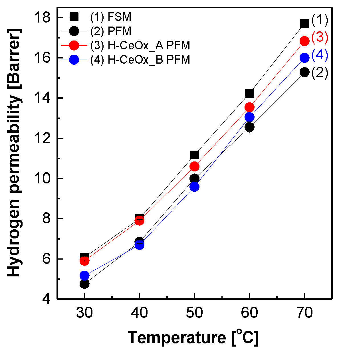
Figure 3 displays the hydrogen permeability of PFSA–PTFE reinforced membranes in addition to FSM. The hydrogen permeation in all the membranes became fast as a function of temperature owing to the increase in hydrogen diffusivity. PFM had hydrogen permeability values lower than those of FSM in the temperature range. Considering that hydrogen permeability values of PTFE were inferior to those of 3M 725EW ionomers, this meant that severe defects or voids that might occur during reinforced membrane preparation were not formed. After the incorporation of CeOx hybrid nanoparticles, the hydrogen permeability values of H–CeOx_A PFM and H–CeOx_B PFM slightly increased, regardless of their identities. It was inferred that the incomplete compatibility between CeOx nanoparticles and 3M 725 ionomer matrices in the resulting reinforced membranes might have induced the formation of interfaces, which weakened the hydrogen barrier properties of the resulting reinforced membranes.
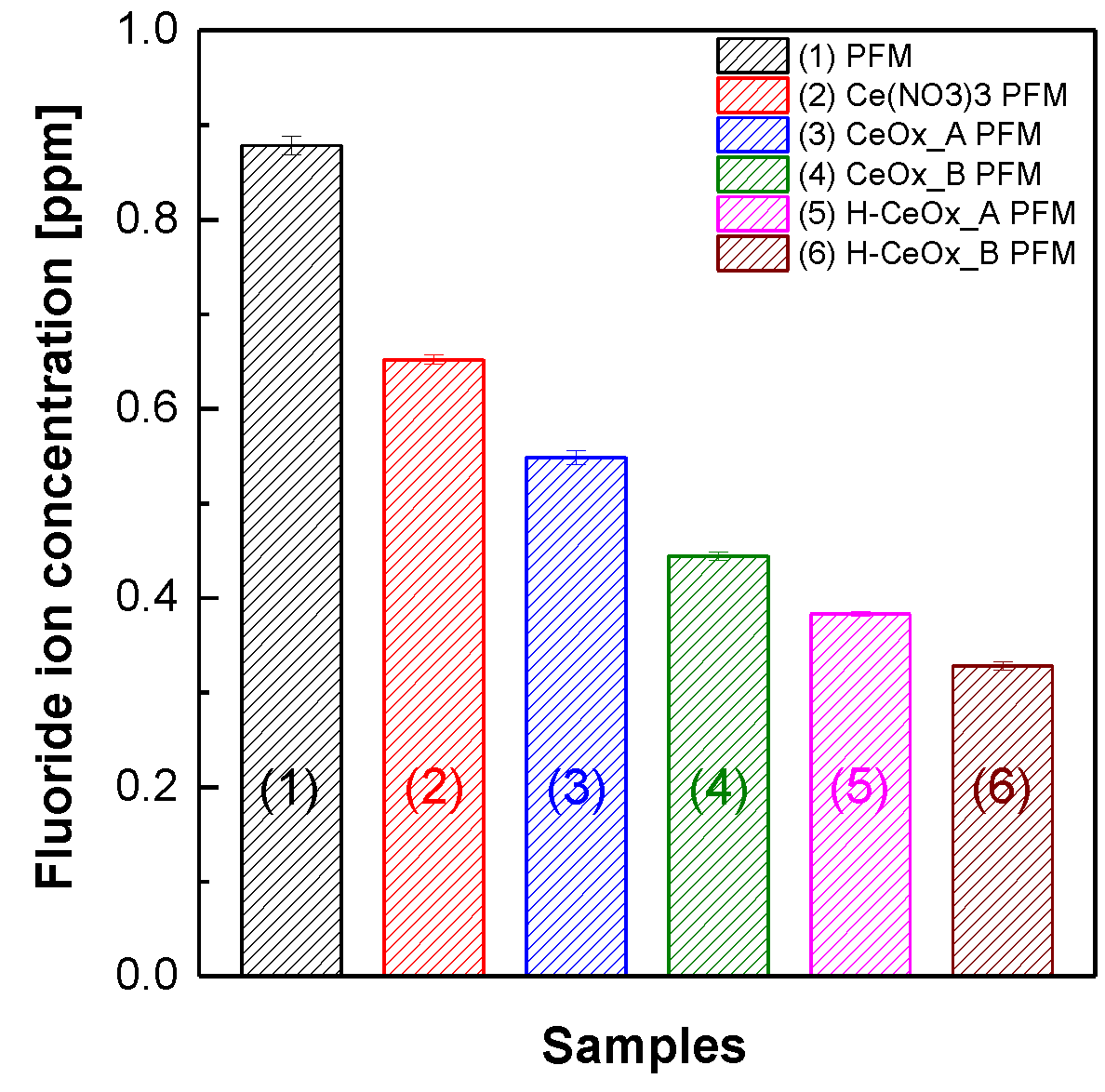
Figure 4 shows the concentration of fluoride ions that were products of the radical-induced chemical decomposition of the side chain and/or the main chain of 3M 725EW ionomer matrices in the reinforced membranes [48,49,50]. Here, the fluoride ions included F and CF3COO [51]. When Ce3+ ions or CeOx hybrid nanoparticles were introduced as radical scavengers, the high fluoride ion concentration of PFM was significantly lowered. Their antioxidant effect, however, seemed to be quite different from each other, in spite of the use of the same cerium element content. The fluoride ion concentration obtained from Ce(NO3)3 PFM was 16–50% higher than those detected from the reinforced membranes containing CeOx hybrid nanoparticles. This implies that CeOx hybrid nanoparticles may be more effective than Ce3+ ions originated from Ce(NO3)3, in eliminating radicals. This trend may be associated with the radical scavenging reaction mechanism depending on the oxidation number of cerium ions. It is known that both Ce3+ and Ce4+ ions can participate in eliminating aggressive radicals (e.g., ·O2) as radical scavenging catalysts following repeated chemical transformation from Ce4+ to Ce3+ and vice versa (see Equation (6) to (7) [52]). More specifically, when Ce4+ ions meet ·O2 chosen as one of the aggressive radicals, Ce4+ ions can be easily converted to Ce3+ ions (Equation (6)). Meanwhile, Ce3+ ions can be altered to Ce4+ ions only with the help of acidic protons. Because Ce3+ ions in Ce(NO3)3 PFM are tightly ionically bound to –SO3 groups of its acidic 3M 725EW ionomer matrices, the reduction reaction of the Ce3+ ions accompanied by the consumption of acidic protons would be certainly slow. It would make the chemical reaction of Equation (7) a rate-determining step in the radical removal mechanism. The slow reaction from Ce3+ to Ce4+ ions seems to be responsible for the weakened antioxidant effect in Ce(NO3)3 PFM.
·O2 + Ce4+ → O2 + Ce3+
·O2 + Ce3+ + 2H+ → H2O2 + Ce4+
This difference in the antioxidant effect between Ce3+ and CeOx hybrid nanoparticles was also observed in CeOx_A PFM and CeOx_B PFM. Under the premise that highly dissociated Ce3+ contents measured via ICP analysis of CeOx_B dispersion (Table 1) were lower than that in CeOx_A dispersion and that the reduced content of the Ce3+ ions was used for the formation of additional CeOx hybrid nanoparticles in CeOx_B dispersion, CeOx_B PFM had CeOx hybrid nanoparticle content higher than CeOx_A PFM. In addition to the influence of CeOx content, it is worth paying attention to the identities of CeOx hybrid nanoparticles. The CeOx hybrid nanoparticles in CeOx_A dispersion are expected to exist mainly in the form of Ce(OH)3 where the oxidation number of cerium ion is +3 (i.e., Ce3+), while the CeOx nanoparticles in CeOx_B dispersion are expected to have a relatively high content of Ce4+ ions, which are derived from Ce(OH)4 and/or CeO2. The high CeOx content and relatively high portion of Ce4+ ions in the CeOx nanoparticles contributed to the improved chemical resistance of CeOx_B PFM compared to CeOx_A PFM when exposed under radical decomposition condition.
Surprisingly, H–CeOx_A PFM and H–CeOx_B PFM obtained after the extraction of Ce3+ via membrane acidification had much improved resistance to the radical decomposition compared to their counterpart membranes CeOx_A PFM and CeOx_B PFM, respectively. This unexpected result might be due to the additional CeOx conversion of the residual Ce3+ ions in CeOx_A PFM and CeOx_B PFM during the membrane acidification and the consequent increase in CeOx content. It is estimated that the boiling H2SO4 treatment used for the membrane acidification was effective enough to transform the residual Ce3+ ions to additional CeOx hybrid nanoparticles.
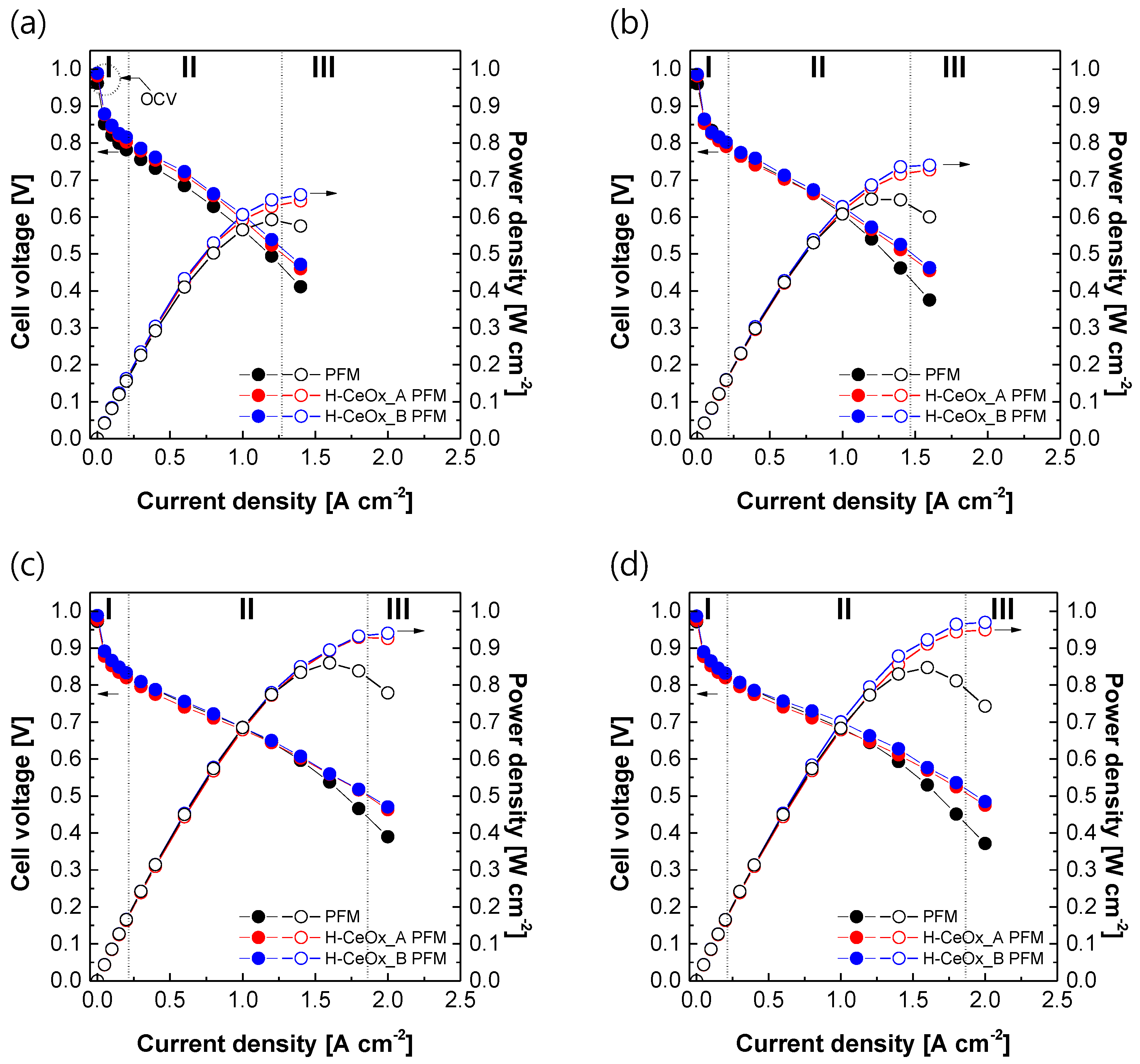
It is important to monitor changes in the electrochemical single cell performance of the reinforced membranes after incorporation of CeOx hybrid nanoparticles. All the cell voltage values in Figure 5a decreased as a function of current density because of overpotentials occurring in activation polarization region (I), ohmic polarization region (II), and concentration polarization region (III), irrespective of which membrane was used. Here, the overpotential means the potential difference between theoretical (i.e., 1.23 V) and actual cell voltages. The cell voltage values in the activation region were affected by the hydrogen barrier properties of the membrane materials. Although there were small differences between the reinforced membranes, their OCV values in the activation polarization region were close to the theoretical cell voltage. This meant that there were no serious defects or voids in the reinforced membranes, which could lead to a rapid reduction in their cell performance during PEMFC operation. Unlike reinforced membranes employing ion-type radical scavengers (e.g., Ce(NO3)3 [53,54,55] and Ce(CH3CO2)3 [56]), critical potential drops in the ohmic polarization region were not observed in either H–CeOx_A PFM or H–CeOx_B PFM. Their electrochemical performance was rather enhanced when compared to radical scavenger-free PFM. The potential drop in the region would depend on proton conduction across the PFSA ionomer located in the whole MEA from anode to cathode through the PEM as well as the contact resistance between the PEM and electrodes. Because all the MEA components were identical and the same MEA fabrication method was applied, this improvement in their electrochemical performance was assumed to be due to proton conductivity being enhanced in H–CeOx_A PFM and H–CeOx_B PFM, with CeOx hybrid nanoparticles acting as additional proton conductors (see Figure 2). H–CeOx_B PFM with a relatively high CeOx content showed current–voltage polarization curve little bit higher than that of H–CeOx_A PFM in the region. The single cell performance was improved further as applied humidity (see Figure 5b) and pressure (Figure 5c) increased. The maximum cell performance was obtained when a pressure of 2 barg and a humidity of 100% RH were applied (see Figure 5d). The electrochemical performance trends between the reinforced membranes were, however, not changed.
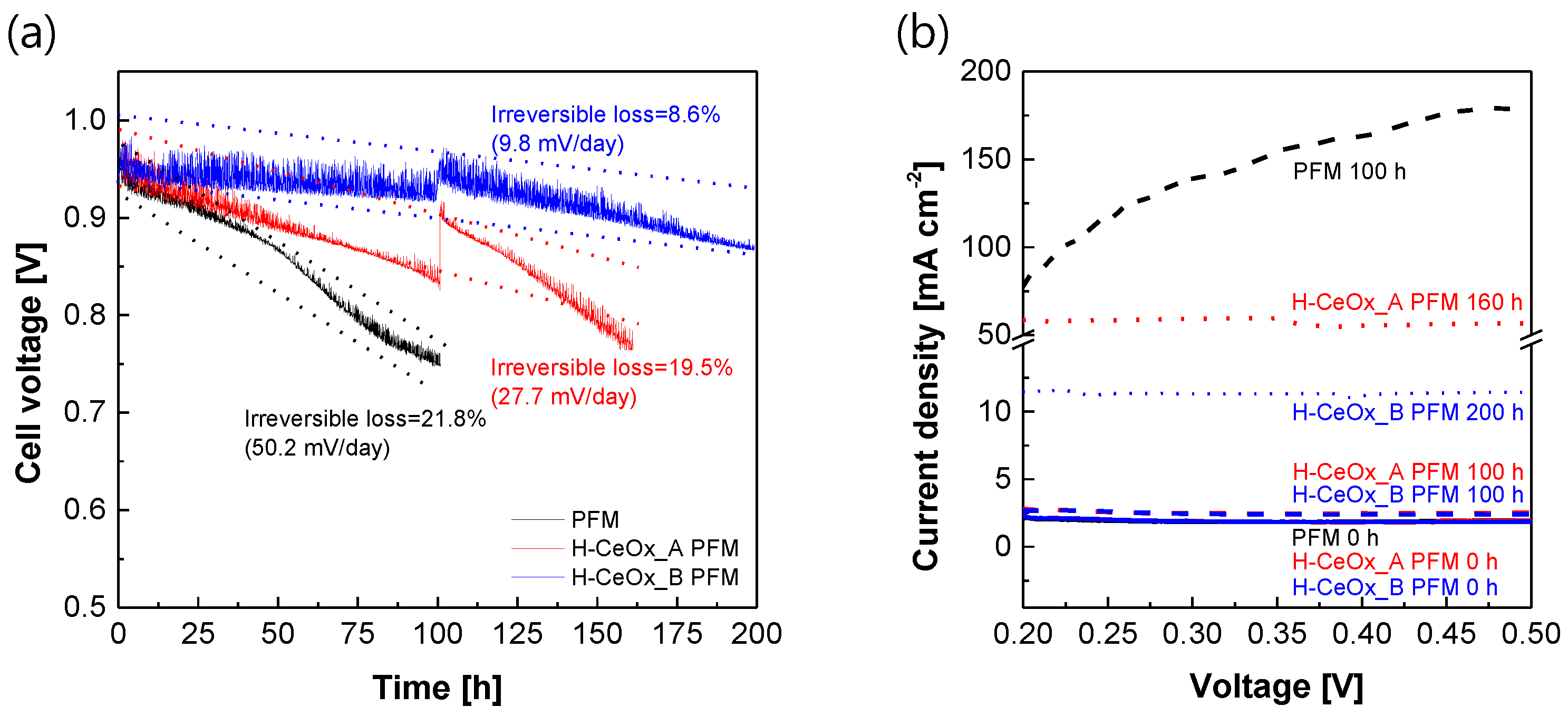
Figure 6 exhibits the electrochemical effectiveness of CeOx hybrid nanoparticles as powerful radical scavengers to extend the service life of the resulting PFSA–PTFE reinforced membranes. As the accelerated test to evaluate chemical stability progressed (Figure 6a), the OCV value of PFM without the CeOx hybrid nanoparticles decreased rapidly up to 20% or more of its initial OCV value within 100 h, showing a very fast irreversible loss rate of 50.2 mV/day. This situation was more severe when its electrochemical hydrogen crossover was observed as a function of time (Figure 6b). The hydrogen crossover in the initial test was stable enough to maintain 1.91 mA/cm2 in the measurement voltage range, but the level after 100 h increased up to 75 to 175 mA/cm2, which far exceeded the hydrogen crossover cutoff of 15 mA/cm2. On the other hand, the service life could be extended by incorporating CeOx hybrid nanoparticles into the resulting reinforced membranes. The content and/or identities of the CeOx hybrid nanoparticles still seemed to play a key role in determining the service life of PFSA–PTFE reinforced membranes. Until 160 h, H–CeOx_A PFM maintained its OCV value within 20% of its initial value, but its hydrogen crossover was beyond the cutoff. In the case of H–CeOx_B PFM, expected to contain a relatively high amount of CeOx nanoparticles based on Ce4+ ions, the improvement in chemical durability was very noticeable. Even after 200 h or more, its irreversible loss did not exceed 9% of the initial value, and the hydrogen crossover was still below the cutoff. The interfacial issue observed in the hydrogen permeability test (Figure 3) did not affect the electrochemical hydrogen crossover. This can be explained as originating from the difference in their measurement environments; the pressure difference on both sides of the sample membrane was 1 and 0 barg in the hydrogen permeability test and LSV test, respectively. Considering that the theoretically calculated cerium element content in H–CeOx_B PFM was at a relatively low level (i.e., 1.7 mg/cm3 in a PFSA matrix or 2.5 µg/cm2 on the basis of a reinforced membrane with a thickness of 15 µm), its electrochemical effect on the chemical durability is meaningful.

4. Conclusions

CeOx hybrid nanoparticles with an average size of 7–8 nm in solid state were successfully synthesized from Ce(NO3)3 through in situ stepwise conversion reactions composed of HCl-catalyzed hydrolysis reaction and NH3OH-catalyzed condensation reaction in an aqueous N-propanol mixture where 3M 725EW ionomer particles were homogeneously distributed. Here, the 3M 725EW ionomer was used as a polymeric dispersant to prevent spontaneous aggregation and subsequent precipitation of CeOx nanoparticles chemically converted in the aqueous medium by making multivalent Ce3+ ions maintain ionic bonding with the –SO3 groups. As the stepwise reactions from acid-catalyzed to base-catalyzed reaction proceeded, the initial Ce3+ ion content decreased and the yield of CeOx conversion increased from 34.4 to 69.1 mol %. The resulting CeOx_A and CeOx_B dispersion maintained stable dispersion phases without any aggregation and precipitation, even in long-term storage for months.
When incorporated as radical scavengers during reinforced membrane formation, CeOx hybrid nanoparticles contributed to improved proton conductivity of H–CeOx_A PFM and H–CeOx_B PFM in comparison to that of CeOx-free reinforced membrane (i.e., PFM). This is attributable to the presence of –OH groups on the CeOx hybrid nanoparticles acting as proton conductors within the acidic 3M 725EW ionomer matrices. The enhancement in their proton conduction capability compensated their potential drops in ohmic polarization region of the current–voltage polarization curves and instead led to improved single cell performance. These aspects were fairly different from those frequently observed in reinforced membranes containing Ce(NO3)3 as a radical scavenger. Moreover, there were no big changes in their hydrogen permeability and initial electrochemical hydrogen crossover levels following the addition of CeOx hybrid nanoparticles. The weak resistance of PFM to free radical attacks was able to be improved to high levels by introducing CeOx hybrid nanoparticles. The increment in radical resistance seemed to depend on both the content of CeOx hybrid nanoparticles and the relative portion of Ce4+ ions in the nanoparticles. H–CeOx_B PFM, with the highest content of CeOx hybrid nanoparticles where the oxidation number of cerium is mainly +4, had the lowest concentration of fluoride ions detected in a Fenton solution, which has been conventionally used to evaluate the radical-induced chemical decomposition of PFSA ionomers. Surprisingly, the fluoride ion concentration was less than half the level detected in Ce(NO3)3 PFM for comparison. The electrochemical effectiveness of CeOx hybrid nanoparticles as radical scavengers was validated using the OCV holding test. The OCV values of H–CeOx_B PFM was continuously kept, showing the lowest irreversible loss and electrochemical hydrogen crossover levels over time.
From the perspective of both electrochemical performance and chemical durability, the strategy of applying CeOx hybrid nanoparticles as radical scavengers, instead of Ce(NO3)3 or conventional CeO2 nanoparticles, appears to be very useful. The CeOx hybrid nanoparticles developed in this study are expected to provide an effective avenue in designing ultimate radical scavengers and applying them. Finally, when highly purified CeOx nanoparticles are applied for PEMs and electrodes, their impact on both electrochemical performance and durability will be addressed in separate publications in membrane- and electrochemistry-oriented journals.

Author Contributions

Conceptualization, J.K. and C.H.L.; methodology, J.A. and M.I.A.; validation, J.K. and C.H.L.; fundamental analysis, J.A., M.I.A. and J.H.L.; electrochemical analysis, Y.P. and I.K.P.; writing—original draft preparation, J.A. and M.I.A.; writing—review and editing, J.K. and C.H.L.; supervision, J.K. and C.H.L.; project administration, C.H.L.; funding and material acquisition, D.D. and L.C. All authors have read and agreed to the published version of the manuscript.

Funding

This work was financially supported by the Technology Development Program to Innovative Hydrogen Energy of the National Research Foundation (NRF) funded by the Ministry of Science, ICT, and Future Planning (2019M3E6A1064093) and by the Technology Innovation Program (20012133) funded by the Ministry of Trade, Industry, and Energy (MOTIE, Korea). This study was supported in part by the 2019 Post Doc. Researcher Supporting Program from Kangwon National University.

Acknowledgments

We thank our colleagues for their contribution to this work.

Conflicts of Interest

The authors declare no conflict of interest.

References

  1. Carrette, L.; Friedrich, K.A.; Stimming, U. Fuel Cells – Fundamentals and Applications. Fuel Cells 2001, 1, 5–39. [Google Scholar] [CrossRef]
  2. Schnurnberger, W. Fuel Cells and Their Applications. KARL KORDESCH. GÜNTER SIMADER VCH Verlagsgesellschaft, Weinheim, 1996, 320 Seiten, geb., DM 248,-, ISBN 3-527-28579-2. Chem. Ing. Tech. 1997, 69, 852. [Google Scholar] [CrossRef]
  3. De Bruijn, F.D.; Dam, V.A.T.; Janssen, G.J.M. Review: Durability and Degradation Issues of PEM Fuel Cell Components. Fuel Cells 2008, 8, 3–22. [Google Scholar] [CrossRef]
  4. Wang, Y.; Chen, K.S.; Mishler, J.; Cho, S.C.; Adroher, X.C. A review of polymer electrolyte membrane fuel cells: Technology, applications, and needs on fundamental research. Appl. Energy 2011, 88, 981–1007. [Google Scholar] [CrossRef] [Green Version]
  5. Wu, J.; Yuan, X.Z.; Martin, J.J.; Wang, H.; Zhang, J.; Shen, J.; Wu, S.; Merida, W. A review of PEM fuel cell durability: Degradation mechanisms and mitigation strategies. J. Power Sources 2008, 184, 104–119. [Google Scholar] [CrossRef]
  6. Zhao, H.; Burke, A.F. Optimization of fuel cell system operating conditions for fuel cell vehicles. J. Power Sources 2009, 186, 408–416. [Google Scholar] [CrossRef] [Green Version]
  7. Kreuer, K. On the development of proton conducting materials for technological applications. Solid State Ionics 1997, 97, 1–15. [Google Scholar] [CrossRef]
  8. Kreuer, K.-D.; Paddison, S.J.; Spohr, E.; Schuster, M. Transport in Proton Conductors for Fuel-Cell Applications: Simulations, Elementary Reactions, and Phenomenology. Chem. Rev. 2004, 104, 4637–4678. [Google Scholar] [CrossRef] [PubMed] [Green Version]
  9. Paddison, S.J. The modelling of molecular structure and ion transport in sulfonic acid based ionomer membranes. J. New. Mat. Electrochem. System 2001, 4, 197–207. [Google Scholar]
  10. Collier, A.; Wang, H.; Yuan, X.Z.; Zhang, J.; Wilkinson, D.P. Degradation of polymer electrolyte membranes. Int. J. Hydrogen Energy 2006, 31, 1838–1854. [Google Scholar] [CrossRef]
  11. Rodgers, M.P.; Bonville, L.J.; Kunz, H.R.; Slattery, D.K.; Fenton, J.M. Fuel Cell Perfluorinated Sulfonic Acid Membrane Degradation Correlating Accelerated Stress Testing and Lifetime. Chem. Rev. 2012, 112, 6075–6103. [Google Scholar] [CrossRef]
  12. Yamaguchi, T.; Ibe, M.; Nair, B.N.; Nakao, S.-I. A Pore-Filling Electrolyte Membrane-Electrode Integrated System for a Direct Methanol Fuel Cell Application. J. Electrochem. Soc. 2002, 149, A1448. [Google Scholar] [CrossRef]
  13. Yamaguchi, T.; Miyata, F.; Nakao, S. Polymer Electrolyte Membranes with a Pore-Filling Structure for a Direct Methanol Fuel Cell. Adv. Mater. 2003, 15, 1198–1201. [Google Scholar] [CrossRef]
  14. Yamaguchi, T.; Miyata, F.; Nakao, S.-I. Pore-filling type polymer electrolyte membranes for a direct methanol fuel cell. J. Membr. Sci. 2003, 214, 283–292. [Google Scholar] [CrossRef]
  15. Yamaguchi, T.; Zhou, H.; Nakazawa, S.; Hara, N. An Extremely Low Methanol Crossover and Highly Durable Aromatic Pore-Filling Electrolyte Membrane for Direct Methanol Fuel Cells. Adv. Mater. 2007, 19, 592–596. [Google Scholar] [CrossRef]
  16. Shim, J.; Ha, H.Y.; Hong, S.-A.; Oh, I.-H. Characteristics of the Nafion ionomer-impregnated composite membrane for polymer electrolyte fuel cells. J. Power Sources 2002, 109, 412–417. [Google Scholar] [CrossRef]
  17. Danilczuk, M.; Coms, F.D.; Schlick, S. Visualizing Chemical Reactions and Crossover Processes in a Fuel Cell Inserted in the ESR Resonator: Detection by Spin Trapping of Oxygen Radicals, Nafion-Derived Fragments, and Hydrogen and Deuterium Atoms. J. Phys. Chem. B 2009, 113, 8031–8042. [Google Scholar] [CrossRef]
  18. Ishimoto, T.; Koyama, M. A Review of Molecular-Level Mechanism of Membrane Degradation in the Polymer Electrolyte Fuel Cell. Membranes 2012, 2, 395–414. [Google Scholar] [CrossRef] [PubMed] [Green Version]
  19. Luo, X.; Ghassemzadeh, L.; Holdcroft, S. Effect of free radical-induced degradation on water permeation through PFSA ionomer membranes. Int. J. Hydrogen Energy 2015, 40, 16714–16723. [Google Scholar] [CrossRef]
  20. Zaton, M.; Rozière, J.; Jones, D. Current understanding of chemical degradation mechanisms of perfluorosulfonic acid membranes and their mitigation strategies: A review. Sustain. Energy Fuels 2017, 1, 409–438. [Google Scholar] [CrossRef]
  21. Chiodelli, G.; Malavasi, L. Electrochemical open circuit voltage (OCV) characterization of SOFC materials. Ionics 2013, 19, 1135–1144. [Google Scholar] [CrossRef]
  22. Park, C.H.; Lee, C.H. Disulfonated copolyimide-boehmite nanocomposite fuel cell membranes with improved chemical resistance. Macromol. Res. 2014, 23, 45–52. [Google Scholar] [CrossRef]
  23. Frey, M.H.; Pierpont, D.M.; Hamrock, S.J. High durability fuel cell components with cerium salt additives. U.S. Patent 9,431,670 B2, 30 August 2016. [Google Scholar]
  24. Wang, L.; Advani, S.G.; Prasad, A.K. Degradation reduction of polymer electrolyte membranes using CeO2 as a free-radical scavenger in catalyst layer. Electrochimica Acta 2013, 109, 775–780. [Google Scholar] [CrossRef]
  25. Lei, M.; Yang, T.; Wang, W.; Huang, K.; Zhang, Y.; Zhang, R.; Jiao, R.; Fu, X.; Yang, H.; Wang, Y.; et al. One-dimensional manganese oxide nanostructures as radical scavenger to improve membrane electrolyte assembly durability of proton exchange membrane fuel cells. J. Power Sources 2013, 230, 96–100. [Google Scholar] [CrossRef]
  26. Xing, D.; Zhang, H.; Wang, L.; Zhai, Y.; Yi, B. Investigation of the Ag-SiO2/sulfonated poly(biphenyl ether sulfone) composite membranes for fuel cell. J. Membr. Sci. 2007, 296, 9–14. [Google Scholar] [CrossRef]
  27. Binks, B.P.; Lumsdon, S.O. Stability of oil-in-water emulsions stabilised by silica particles. Phys. Chem. Chem. Phys. 1999, 1, 3007–3016. [Google Scholar] [CrossRef]
  28. Adjemian, K.T.; Dominey, R.; Krishnan, L.; Ota, H.; Majsztrik, P.; Zhang, T.; Mann, J.; Kirby, B.; Gatto, L.; Velo-Simpson, M.; et al. Function and Characterization of Metal Oxide−Nafion Composite Membranes for Elevated-Temperature H2/O2 PEM Fuel Cells. Chem. Mater. 2006, 18, 2238–2248. [Google Scholar] [CrossRef]
  29. Apichatachutapan, W.; Moore, R.B.; Mauritz, K.A. Asymmetric nafion/(zirconium oxide) hybrid membranes via in situ sol-gel chemistry. J. Appl. Polym. Sci. 1996, 62, 417–426. [Google Scholar] [CrossRef]
  30. Ahn, C.-Y.; Ahn, J.; Kang, S.Y.; Kim, O.-H.; Lee, D.W.; Lee, J.H.; Shim, J.G.; Lee, C.H.; Cho, Y.-H.; Sung, Y.-E. Enhancement of service life of polymer electrolyte fuel cells through application of nanodispersed ionomer. Sci. Adv. 2020, 6, eaaw0870. [Google Scholar] [CrossRef] [Green Version]
  31. Lee, C.H.; Lee, K.-S.; Lane, O.; McGrath, J.E.; Chen, Y.; Wi, S.; Lee, S.Y.; Lee, Y.M. Solvent-assisted thermal annealing of disulfonated poly(arylene ether sulfone) random copolymers for low humidity polymer electrolyte membrane fuel cells. RSC Adv. 2011, 2, 1025–1032. [Google Scholar] [CrossRef]
  32. Li, Y.; Wang, F.; Yang, J.; Liu, D.; Roy, A.; Case, S.; Lesko, J.; McGrath, J.E. Synthesis and characterization of controlled molecular weight disulfonated poly(arylene ether sulfone) copolymers and their applications to proton exchange membranes. Polymer 2006, 47, 4210–4217. [Google Scholar] [CrossRef]
  33. Sumner, M.; Harrison, W.; Weyers, R.; Kim, Y.; McGrath, J.; Riffle, J.; Brink, A.; Brink, M. Novel proton conducting sulfonated poly(arylene ether) copolymers containing aromatic nitriles. J. Membr. Sci. 2004, 239, 199–211. [Google Scholar] [CrossRef]
  34. Wang, F.; Hickner, M.; Kim, Y.S.; Zawodzinski, T.A.; McGrath, J.E. Direct polymerization of sulfonated poly(arylene ether sulfone) random (statistical) copolymers: Candidates for new proton exchange membranes. J. Membr. Sci. 2002, 197, 231–242. [Google Scholar] [CrossRef]
  35. Lee, C.H.; Park, H.B.; Lee, Y.M.; Lee, R.D. Importance of Proton Conductivity Measurement in Polymer Electrolyte Membrane for Fuel Cell Application. Ind. Eng. Chem. Res. 2005, 44, 7617–7626. [Google Scholar] [CrossRef]
  36. Rutherford, S.W.; Do, D.D. Review of time lag permeation technique as a method for characterisation of porous media and membranes. Adsorption 1997, 3, 283–312. [Google Scholar] [CrossRef]
  37. Fuel Cell Technical Team Roadmap, Driving Research and Innovator for Vehicle Efficiency and Energy Sustainability. Available online: https://www.energy.gov/eere/vehicles/downloads/us-drive-fuel-cell-technical-team-roadmap (accessed on 27 November 2017).
  38. Calvache-Muñoz, J.; Prado, F.A.; Rodríguez-Páez, J.E. Cerium oxide nanoparticles: Synthesis, characterization and tentative mechanism of particle formation. Colloids Surfaces A Physicochem. Eng. Asp. 2017, 529, 146–159. [Google Scholar] [CrossRef]
  39. He, H.-W.; Wu, X.-Q.; Ren, W.; Shi, P.; Yao, X.; Song, Z.-T. Synthesis of crystalline cerium dioxide hydrosol by a sol–gel method. Ceram. Int. 2012, 38, S501–S504. [Google Scholar] [CrossRef]
  40. Nabavi, M.; Spalla, O.; Cabane, B. Surface Chemistry of Nanometric Ceria Particles in Aqueous Dispersions. J. Colloid Interface Sci. 1993, 160, 459–471. [Google Scholar] [CrossRef] [Green Version]
  41. Abellan, P.; Moser, T.H.; Lucas, I.T.; Grate, J.W.; Evans, J.E.; Browning, N.D. The formation of cerium(iii) hydroxide nanoparticles by a radiation mediated increase in local pH. RSC Adv. 2017, 7, 3831–3837. [Google Scholar] [CrossRef] [Green Version]
  42. Sayle, T.X.T.; Molinari, M.; Das, S.; Bhatta, U.M.; Möbus, G.; Parker, S.C.; Seal, S.; Sayle, D.C. Environment-mediated structure, surface redox activity and reactivity of ceria nanoparticles. Nanoscale 2013, 5, 6063–6073. [Google Scholar] [CrossRef] [Green Version]
  43. Cerium (IV) Oxide. Available online: https://en.wikipedia.org/wiki/Cerium(IV)_oxide (accessed on 29 January 2021).
  44. Barany, S.; Bohacs, K.; Chepurna, I.; Meszaros, R. Electrokinetic properties and stability of cerium dioxide suspensions. RSC Adv. 2016, 6, 69343–69351. [Google Scholar] [CrossRef]
  45. Gulicovski, J.J.; Bračko, I.; Milonjić, S.K. Morphology and the isoelectric point of nanosized aqueous ceria sols. Mater. Chem. Phys. 2014, 148, 868–873. [Google Scholar] [CrossRef]
  46. Chanteau, B.; Fresnais, J.; Berret, J.-F. Electrosteric Enhanced Stability of Functional Sub-10 nm Cerium and Iron Oxide Particles in Cell Culture Medium. Langmuir 2009, 25, 9064–9070. [Google Scholar] [CrossRef] [Green Version]
  47. Sehgal, A.; Lalatonne, Y.; Berret, J.-F.; Morvan, M. Precipitation−Redispersion of Cerium Oxide Nanoparticles with Poly(acrylic acid): Toward Stable Dispersions. Langmuir 2005, 21, 9359–9364. [Google Scholar] [CrossRef] [PubMed] [Green Version]
  48. Curtin, D.E.; Lousenberg, R.D.; Henry, T.J.; Tangeman, P.C.; Tisack, M.E. Advanced materials for improved PEMFC performance and life. J. Power Sources 2004, 131, 41–48. [Google Scholar] [CrossRef]
  49. Inaba, M.; Sugishita, M.; Wada, J.; Matsuzawa, K.; Yamada, H.; Tasaka, A. Impacts of air bleeding on membrane degradation in polymer electrolyte fuel cells. J. Power Sources 2008, 178, 699–705. [Google Scholar] [CrossRef]
  50. Kinumoto, T.; Inaba, M.; Nakayama, Y.; Ogata, K.; Umebayashi, R.; Tasaka, A.; Iriyama, Y.; Abe, T.; Ogumi, Z. Durability of perfluorinated ionomer membrane against hydrogen peroxide. J. Power Sources 2006, 158, 1222–1228. [Google Scholar] [CrossRef]
  51. Chen, C.; Fuller, T.F. The effect of humidity on the degradation of Nafion® membrane. Polym. Degrad. Stab. 2009, 94, 1436–1447. [Google Scholar] [CrossRef]
  52. Xu, C.; Qu, X. Cerium oxide nanoparticle: A remarkably versatile rare earth nanomaterial for biological applications. NPG Asia Mater. 2014, 6, e90. [Google Scholar] [CrossRef]
  53. Akrout, A.; Delrue, A.; Zatoń, M.; Duquet, F.; Spanu, F.; Taillades-Jacquin, M.; Cavaliere, S.; Jones, D.; Rozière, J. Immobilisation and Release of Radical Scavengers on Nanoclays for Chemical Reinforcement of Proton Exchange Membranes. Membranes 2020, 10, 208. [Google Scholar] [CrossRef] [PubMed]
  54. Baker, A.M.; Dumont, J.H.; Mukundan, R.; Advani, S.G.; Prasad, A.K.; Spernjak, D.; Borup, R.L. The Effects of Cerium Migration on PEM Fuel Cell Performance. ECS Trans. 2017, 80, 643–650. [Google Scholar] [CrossRef]
  55. D’Urso, C.; Oldani, C.; Baglio, V.; Merlo, L.; Aricò, A. Towards fuel cell membranes with improved lifetime: Aquivion® Perfluorosulfonic Acid membranes containing immobilized radical scavengers. J. Power Sources 2014, 272, 753–758. [Google Scholar] [CrossRef]
  56. Baker, A.M.; Williams, S.T.D.; Mukundan, R.; Spernjak, D.; Advani, S.G.; Prasad, A.K.; Borup, R.L. Zr-doped ceria additives for enhanced PEM fuel cell durability and radical scavenger stability. J. Mater. Chem. A 2017, 5, 15073–15079. [Google Scholar] [CrossRef]
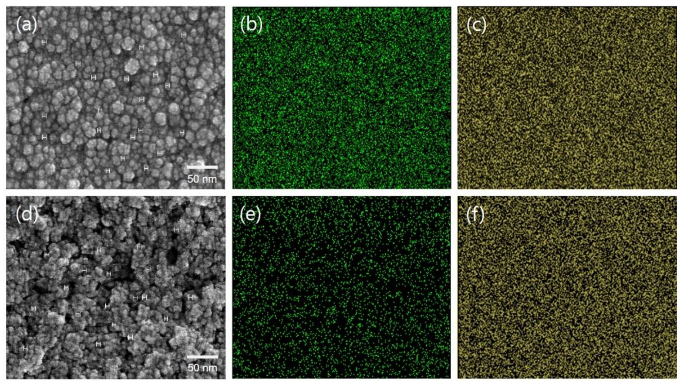
Figure 1. (a,d) FE-SEM and (b,c,e,f) EDX mapping images ((b,e) cerium and (c,f) oxygen element) of (ac) CeOx_A–3M ionomer hybrid nanoparticles and (df) CeOx_B–3M ionomer hybrid nanoparticles in the solid state obtained after drying each dispersion.
Membranes 11 00143 g001
Figure 2. Proton conductivity of perfluorinated sulfonic acid–poly(tetrafluoroethylene) (PFSA–PTFE) reinforced membranes in deionized water. The freestanding membrane (FSM) was made up of 3M 725EW ionomer.
Membranes 11 00143 g002
Figure 3. The hydrogen permeability of PFSA–PTFE reinforced membranes measured via time-lag method.
Membranes 11 00143 g003
Figure 4. The concentration of fluoride ions detected after the chemical degradation of PFSA–PTFE reinforced membranes in a Fenton solution at 80 °C for 2 h.
Membranes 11 00143 g004
Figure 5. The current–voltage polarization curves of PFSA–PTFE reinforced membranes obtained at 65 °C according to changes in applied pressure ((a,b) 1.0 barg and (c,d) 2.0 barg) and humidity ((a,c) 50% relative humidity (RH) and (b,d) 100% RH) values.
Membranes 11 00143 g005
Figure 6. (a) Open-circuit voltage (OCV) values of PFSA–PTFE reinforced membranes as a function of operation time at 90 °C and 30% RH under the pressure of 1.5 barg. (b) Hydrogen crossover obtained with the interval of 100 h via linear sweep voltammetry (LSV) analysis, which was conducted at 65 °C and 50% RH under the pressure of 1.0 barg.
Membranes 11 00143 g006
Table 1. Dispersion characteristics depending on CeOx conversion reaction conditions.
SampleAverage Particle Size
[nm]
Ce3+ Concentration [ppm] dCeOx Conversion f [mol%]
t e = 0t e = 12t e = 24t e = 12t e = 24
Pristine dispersion a2.2 ± 0.200000
Ce(NO3)3 dispersion2.8 ± 0.3 b15,200 b
CeOx_A dispersion61 ± 2 c15,200 b13,70010,0009.8734.2
CeOx_B dispersion152 ± 5 c15,200 b9700470036.269.1
a 5 wt % aqueous dispersion of 3M 725EW ionomer without any CeOx nanoparticles; b measured immediately after the Ce(NO3)3 dissolution; c measured using each dispersion obtained after the chemical reaction for 24 h; d measured via inductively coupled plasma optical emission spectroscopy; e reaction time in hours; f CeOx conversion = [(Ce3+ concentration at t = 0 – Ce3+ concentration at t = 12 or 24)/(Ce3+ concentration at t = 0)] × 100.
Publisher’s Note: MDPI stays neutral with regard to jurisdictional claims in published maps and institutional affiliations.