Article

Improvement of Membrane Distillation Using PVDF Membrane Incorporated with TiO2 Modified by Silane and Optimization of Fabricating Conditions

1
Department of Environmental Engineering, Program in Environmental and Polymer Engineering, Inha University, Inharo 100, Michuholgu, Incheon 22212, Korea
2
Department of Bioresources and Rural System Engineering, Hankyong National University, Anseong 17579, Korea
*
Author to whom correspondence should be addressed.
Membranes 2021, 11(2), 95; https://doi.org/10.3390/membranes11020095
Submission received: 18 December 2020 / Revised: 26 January 2021 / Accepted: 26 January 2021 / Published: 29 January 2021
(This article belongs to the Special Issue Membranes for Environmental Applications 2020)

Abstract

:
The objectives in this study are to improve the performance of PVDF membrane by incorporating TiO2 and silane at various dosages and optimize fabricating conditions by using response surface methodology (RSM) for membrane distillation (MD) application. The PVDF membrane was synthesized by phase inversion method using various TiO2, silane and polymer concentrations. Membranes were characterized by performing contact angle measurements, SEM and FTIR observations. Ammonia rejection and permeate flux were measured by operating a direct contact distillation module treating ammonium chloride solution. A PVDF membrane created by adding TiO2 modified by silane improved membrane hydrophobicity. However, the effect of silane on membrane hydrophobicity was less pronounced at higher TiO2 concentrations. Highest ammonium rejection was associated with the highest membrane hydrophobicity. RSM analysis showed that fabricating conditions to achieve highest flux (10.10 L/m2·h) and ammonium rejection (100.0%) could be obtained at 31.3% silane, 2.50% TiO2, and 15.48% polymer concentrations. With a PVDF-TiO2 composite membrane for MD application, the effect of TiO2 was dependent upon silane concentration. Increasing silane concentration improved membrane hydrophobicity and ammonium rejection. RSM analysis was found to bea useful way to explore optimum fabricating conditions of membranes for the permeate flux and ammonium rejection in MD.

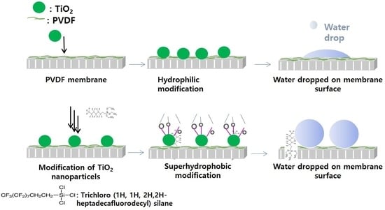
Graphical Abstract

1. Introduction

Membrane distillation (MD) is a separation technology using temperature differences through a hydrophobic membrane. With MD membrane, separation occurs by the transport of water vapor, which is driven by the transmembrane temperature between feed solution and membrane permeate [1,2]. Operated at a very low pressure, the MD separation provides excellent permeate quality, requiring much low-fouling potential as compared to that observed with high pressure-driven membrane separation such as reverse osmosis (RO) membrane filtration [3,4]. With the advantages mentioned, MD membrane has been widely applied to remove salinity as an alternative to RO membrane for seawater desalination. However, not much information is available to understand the performance of an MD membrane for wastewater treatment applications. Inthis regard, membrane materials play a core role in determining the performance of MD membrane in wastewater treatment, but few research studies have been conducted to investigate and optimize the combined effect of fabricating conditions on it. Membrane materials designed for MD processesare often required to have a high porosity and low thermal conduction. Most importantly, intrinsic properties of membrane materials such as hydrophobicity are required to avoid the aqueous solution from its entering into a dry pore matrix. Membrane hydrophobicity can determine the extent to which pore wetting occurs; thus, the loss of membrane hydrophobicity can often lead to high mass transfer resistance against membrane due to the formation of membrane poresthat are filled by the liquid, thus subsequently deteriorating MD performance [5].
In recent years, the use of inorganic nanocomposite materials has expanded significantly with MD membrane to reduce membrane fouling. A range of nanoparticles such as SiO2, ZnO and TiO2 [1] have been added to various polymeric membranes as shown in Table 1. Among them, TiO2 has been paid much attention because of its wide availability and high physicochemical properties, as well as its antifouling capabilities [1,2,3]. Membranes applied in MD process consists mainly of hydrophobic characteristics by using appropriate polymers such as polypropylene (PP), polytetrafluoroethylene (PTFE) and polyvinylidene fluoride (PVDF) [4], as also summarized in Table 1. Among them, PVDF is preferable as aphase separation method to synthesize the MD membrane due to high solubility in various solvents and wide application in the MD process [5].
Nevertheless, polymeric membranes for the MD process are inherently prone to be fouled easily with pore wetting due to hydrophobic–hydrophobic interactions between organic contaminants and membrane materials [6,7,8,9]. Prior to applying inorganic additives to improve the performance of MD membrane, they are modified chemically by coupling the silane not only to improve membrane hydrophobicity but also preventing aggregation of nanoparticles embedded in the membrane matrix. The silane coupling is responsible for reducing the hydrophilic nature of inorganic particles and their surface energy [10,11]. Although the desired compound can be concentrated by the MD membrane effectively, its recovery can be reduced due to the loss of hydrophobicity of the membrane [10,11,12]. Therefore, maintaining membrane hydrophobicity should be core to determiningthe performance of MD membrane in wastewater treatment.
Although the importance of MD technology has been growing rapidly in wastewater treatment, the main obstacle in MD membranes for the treatment of a characteristic environmental pollutant is the rejection of inorganic contaminants, such as ammonium ions. However, few efforts have been made to optimize the fabricating conditions of membrane materials with respect to ammonium rejection in MD applications efficiently.Direct contact membrane distillation (DCMD) was applied as a post-treatment followed by the anaerobic membrane bioreactor (AnMBR), where ammonium removal efficiency is quite limited. As a commercial PVDF membrane was used, a previous study showed that about 76–94% of ammonium rejection efficiency could be obtained by using the permeate produced by an anaerobic membrane bioreactor (AnMBR) system treating low-strength wastewater [13].
Shortfalls of strategies to improve membrane materials have encouraged suggestions for further research in MD application. Shifting the hydrophobicity toward superhydrophobicity helps to introduce an air gap between liquid droplet and membrane surface [14]. This air gap provides an opportunity to increase the allowable pore sizes prior to the occurrence of pore wetting, consequently ensuring higher mass flux [15]. Coating with inorganic nanoparticles such as TiO2 or SiO2 on membrane surfaces has allowed the formation of hierarchical structure for superhydrophobic surfaces. Recently, fluorosilanized TiO2 nanoparticles were embedded in microporous PVDF membranes, displaying a hierarchical structure with multilevel roughness. The derived membrane showed superhydrophobicity with desirable anti-fouling properties [16]. Deposit of salt within membrane pores also decreased because the extent of partial wetting could be reduced by coating the TiO2 on the membrane [7]. On the other hand, MD membrane was studied for the treatment of silane in the presence of organic compound by using a modified TiO2-PVDF membrane. It was found that membrane hydrophobicity significantly contributed organic removal efficiency such as phenol compound [17].
In spite of many efforts to fabricate mixed matrix membranes for MD applications, the efficacy of silanized TiO2-embedded PVDF membranes on the rejection of inorganic pollutants such as ammonium still needs to be studied and optimized. Furthermore, membrane synthesis has been carried out by applying the conventional ways involving variation of one parameter while the others remain constant. This method often requires many experimental runs to find out optimum fabricating conditions, which needs a significant amount of time and chemicals [18,19]. Although the feasibility of TiO2-modified membranes has been studied for MD applications, optimizing fabricating conditions is needed to evaluate new membrane materials for inorganic rejection efficiency.
In this work, PVDF membranes were fabricated by incorporating them with TiO2 nanoparticles coupled with 1H, 1H, 2H, 2H-heptadecafluorodecyl silane for improving membrane hydrophobicity in direct contact membrane distillation (DCMD) application to investigate combined effects of fabricating conditions on ammonium rejection and membrane permeability. To overcome the limitations of conventional methods to determine fabricating condition, response surface methodology (RSM), which is well-known as a statistical approach, was conducted in this study to optimize it by evaluating the Box-Behnken model design and analyzing experimental factors with small experimental runs. Three independent variables, including concentrations of TiO2, silane and polymer concentration, were selected.

2. Materials and Methods

2.1. Chemicals

PVDF powder was purchased from Alfa Aesar (Ward hill, MA, USA) and dried at 100 °C before being used. N-methyl-2-pyrrolidone (NMP) (>99.5%) (Daejung Chemicals and Metals, Gyeonggi-do, Korea) was used as the polymer solvent. TiO2 nanoparticles of 21 nm as primary particle size and higher than 99.5% trace metal basis for doping solution were acquired from Sigma-Aldrich (St. Louis, MO, USA). The other additives of the doping solution, including ortho-phosphoric acid (H3PO4) (>85%) and acetone, were purchased from Merck (Darmstadt, Germany). Ethanol was used as silanation solvent. The trichloro (1H, 1H, 2H, 2H-heptadecafluorodecyl) silane, which is acquired by TCI (Tokyo, Japan) was used in this study. For MD experiment, a 35 mg/L of ammonium chloride (NH4Cl, Duksan Pure Chemicals, Gyungggi-do, Korea) was prepared as a feed solution in deionized (DI) water.

2.2. Synthesis and Modification of PVDF Membrane

Membranes were synthesized by phase inversion method according to the literature [17]. PVDF powder was dried at 100 °C for 24 h to remove its moisture content before preparing the doping solution. The dried PVDF at different concentrations was mixed with N-Methyl-2-Pyrorolidone (NMP) solvent and non-solvent additives including acetone (5 wt%) and H3PO4 (3 wt%) to improve the porous structure. The mixture of the solution was stirred for 24 h at 50 °C before degassing for another 24 h. The solution was cast on a polyester nonwoven fabric placed on a glass plate with a casting knife with 250 µm thickness (Elcometer) at room temperature. The casted film was immersed into a coagulation bath containing pure ethanol for 15 min. After this, the membrane was immersed into a second coagulation bath containing DI water for 24 h. The wet membrane was then dried in the oven at 50 °C for 72 h. For silane modification, silane was mixed with ethanol at various concentrations, and then it was stirred for 30 min. The TiO2 nanoparticles were added into the silane solution for 5 min and separated by 1.2 µm glass-fiber filtration. The TiO2 nanoparticles obtained were rinsed by using ethanol to remove residual silane and then dried in the oven at 50 °C for 24 h before being used in the dope solution. The membranes were characterized and tested by using the MD module for treating ammonium chloride solution. Fabrication conditions applied in this study are summarized in Table 2.

2.3. Membrane Characterization

The contact angle on the membrane surface was measured by using Contact Angle Analyzer (Surfatech, GSA-X, Vendargues, France) to investigate the change of membrane hydrophobicity. DI water was dropped through a syringe onto the membrane surface at room temperature. Replicate measurement was conducted at three different positions on the membrane surface. Liquid entry pressure (LEP) is a measurement of the ability of a hydrophobic membrane against pore wetting, and it can be obtained using a dead-end filtration cell (Sterlitech, Kent, WA, USA, HP4750). The reservoir was first filled with DI water, and then a dry membrane sample was tightly secured in the cell. The pressure was increased stepwise after a 5 min waiting period. The appearance of the first drop output was taken as a liquid entry pressure [10]. Membrane porosity, ε (%), was determined by a gravimetric method. A membrane sample with a weight of W1 (g) was immersed in ethanol for 2 h. After that, the sample was taken out and weighed after both of its sides were wiped off by absorbent cotton. Then, the weight of the wetted sample was measured again, W2 (g). W3 (g) was the weight of ethanol absorbed separately by the non-woven support layer. Equation (1) was used to determine the porosity, where ρ (g/cm3) is the density of ethanol, A (cm2) is the membrane area, δ1 (cm) is the total membrane thickness and δ2 (cm) is the non-woven support layer thickness. Five membrane samples were measured to obtain the average value.
ε = ( w 2 w 1 w 3 ) / ρ ( δ 1 δ 2 ) × A
Fresh and used membranes were observed by Fourier transform infrared spectroscopy (FT-IR) (Bruker VERTEX 80V, Billerica, MA, USA). Surface morphology of membranes was further observed using scanning electron microscopy (SEM) (SEM, FEI Inspect F50, Westborough, MA, USA) coupled with EDX in order to analyze the surface composition of the membrane. The permeate quality produced by the MD membrane was analyzed by employing the persulfate digestion to measure ammonia nitrogen using a reagent kit (Hach, 2672145, Loveland, CO, USA). Topography images of the membrane surfaces were obtained by using atomic force microscopy (AFM, NX-10, Park Systems, Jeju, Korea). The scanning area was XY (150 µm) and Z (5 µm), and the type of probe wasSi-N, working in tapping mode.

2.4. Experimental Set-Up ofDirect Contact Membrane Distillation

The MD filtration was performed by applying a laboratory-scale direct contact membrane distillation (DCMD) experimental set-up consisting of a membrane module and feed and permeate reservoirs as shown in Figure 1. The feed reservoir was placed into a water bath equipped with a temperature controller. The feed solution consisting of 35 mg/L ammonium chloride (NH4Cl) was heated by elevating the temperature to 60 °C through the water bath to allow only vapor across the membrane. The vapor formed from the membrane was then condensed by DI water filled in the permeate reservoir at constant temperature of 25 °C. Gear pumps (WT3000-1FA, Longerpump, China) were used to recirculate feed and permeate stream through water channels of MD membrane module at the same flow rate of 500 mL/min. The permeate flux of the membranes prepared, J, was calculated by the following equation
J = m ρ × A m × t
where J is the permeate flux (L/m2·h), m is the mass of permeate (kg), Am is the effective area of membrane (m2), t is the distillation time (h), and ρ is the density of permeate solution, which is 1 g/cm3. The rejection coefficient, R (%) was calculated according to the following equation:
R = [ 1 C p C F ] × 100
where CF is the concentration of the feed (g/L) and Cp is the concentration of permeate (g/L). In addition, relative flux was determined to understand the flux decline pattern,
Relative   flux   =   J Jw
where J is the permeate flux measured with ammonium chloride in the feed and Jw is permeate flux measured with pure water as the feed.

2.5. RSM for Experimental Design and Optimization

RSM reduces process time and production cost to obtain the optimum condition of the membrane synthesis. Three independent variables (silane, TiO2 and polymer concentration) were considered for optimization, while the response variables were the permeate flux (L/m2·h) and ammonium rejection (%). Design-Expert statistical software (version 7.0.0. STAT-EASE Inc., Minneapolis, MN, USA) was used to compile the 17 sets of experimental conditions and analyze them based on the Box–Behnken model. The variables and levels selected for the study are shown in Table 3. The experimental data obtained based on the above design was fitted to a second-order polynomial equation. A quadratic model used for generated response surfaces is represented as follows:
Y = a 0 + a 1 A + a 2 B + a 3 C + a 12 A B + a 13 A C + a 23 B C + a 11 A 2 + a 22 B 2 + a 33 C 2
where Y: the predicted permeate flux (L/m2·h) or ammonium rejection (%); a0: the constant coefficient; ai, aii and aii: the linear, quadratic, and interaction coefficients respectively; A: silane concentration (wt%); B: TiO2 concentration (wt%); and C: polymer concentration (wt%). The regression analysis, statistical significance and response surfaces were justified through analysis of variance (ANOVA).

3. Results and Discussion

3.1. Membrane Porosity

As shown in Table 2, at the same silane (25.7%) and TiO2 concentrations (1.5%), membrane porosity decreased from 62.1 to 50.4% when polymer concentration increased from 14 to 16 wt%.As silane concentration was reduced to 17.1% while TiO2 concentration increased to 2%, a similar result was observed, namely that increasing the polymer concentration reduced the membrane porosity (67.8% vs. 52.1%). In other aspects, porosity changes can be attributed to the fact that increasing polymer concentration suppresses macro-void structure because the exchange rate between solvent and non-solvent becomes faster. In addition, with a higher ratio of water concentration to polymer concentration, higher porosity of membrane can be formed [25].
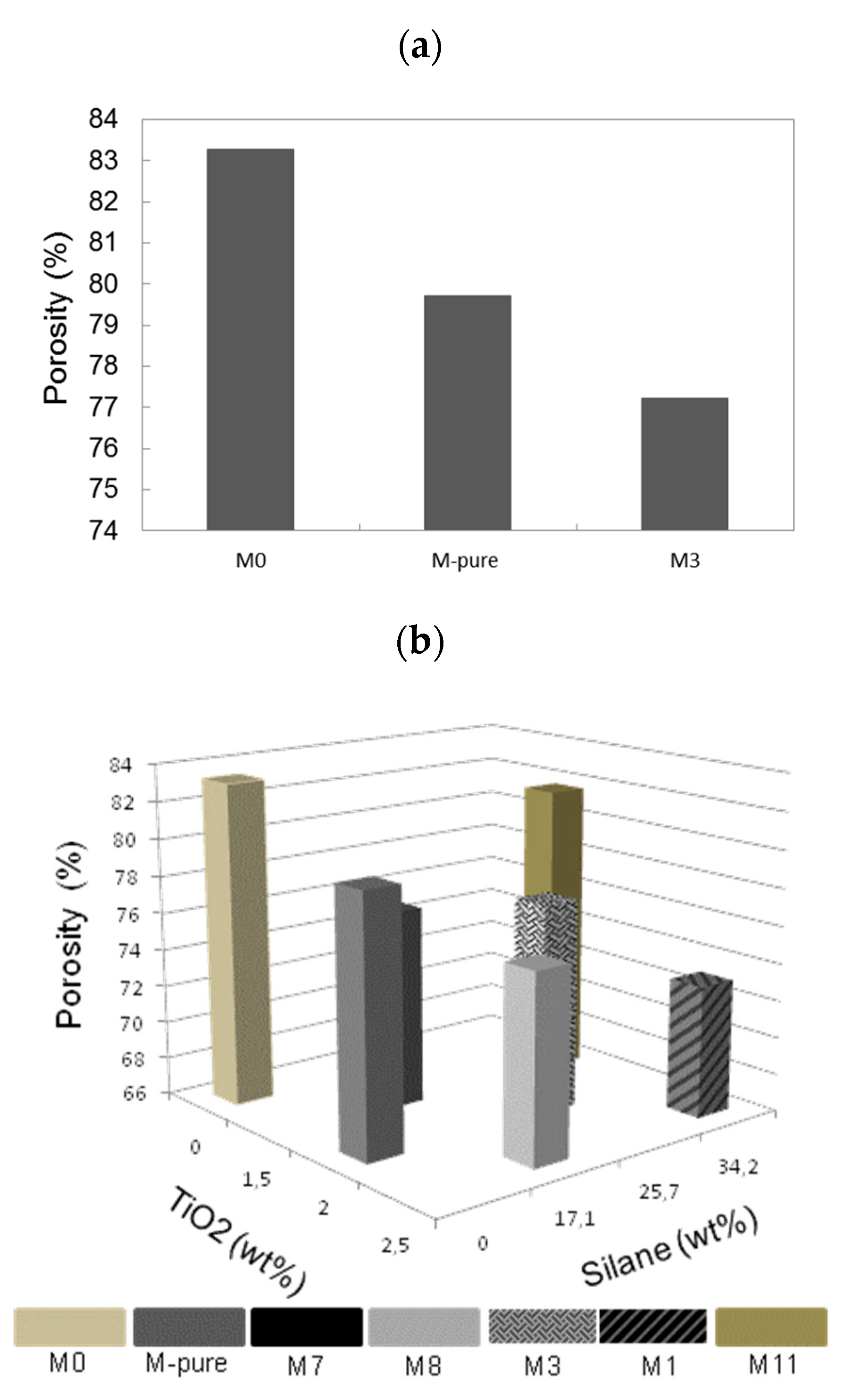
Figure 2a shows the effect of TiO2 and silane concentrations on membrane porosity. At 15 wt% of PVDF, M0 membrane without adding the silane and TiO2 achieved the highest membrane porosity of 83.2%. With ethanol as the first coagulation bath resulting in PVDF membranes with high porosity, demixing rate during the phase inversion can influence the formation of membrane pore size and porosity [26]. Nevertheless, adding the 2 wt% of TiO2 into the PVDF membrane enhanced thermodynamic instability, thus decreasing the effective time required for the growth of membrane pore structure, which later produced a membrane that was less porous at 79.7% porosity [27]. For both unmodified and modified TiO2–PVDF membranes, the porosity of PVDF membrane was reduced, probably due to the aggregation of TiO2 particles within membrane pore matrix to 79.7% and 77.2% for M-pure and M3, respectively (Supplementary Materials Figure S1). On the other hand, the membrane porosity was affected by TiO2 and silane concentration as shown in Figure 2b. At 15 wt% of PVDF and 17.1 wt% of silane concentration, increasing the TiO2 dosage from 1.5 to 2.5 wt% reduced the membrane porosity from 76.6 to 75.9% slightly probably due to a hindrance effect of nanoparticles during phase inversion process. In addition, under the same silane concentration (34.2 wt%) and polymer concentration (15 wt%), membrane porosity decreased from 81.6 to 73.0% as TiO2 concentration increased from 1.5 to 2.5 wt%.
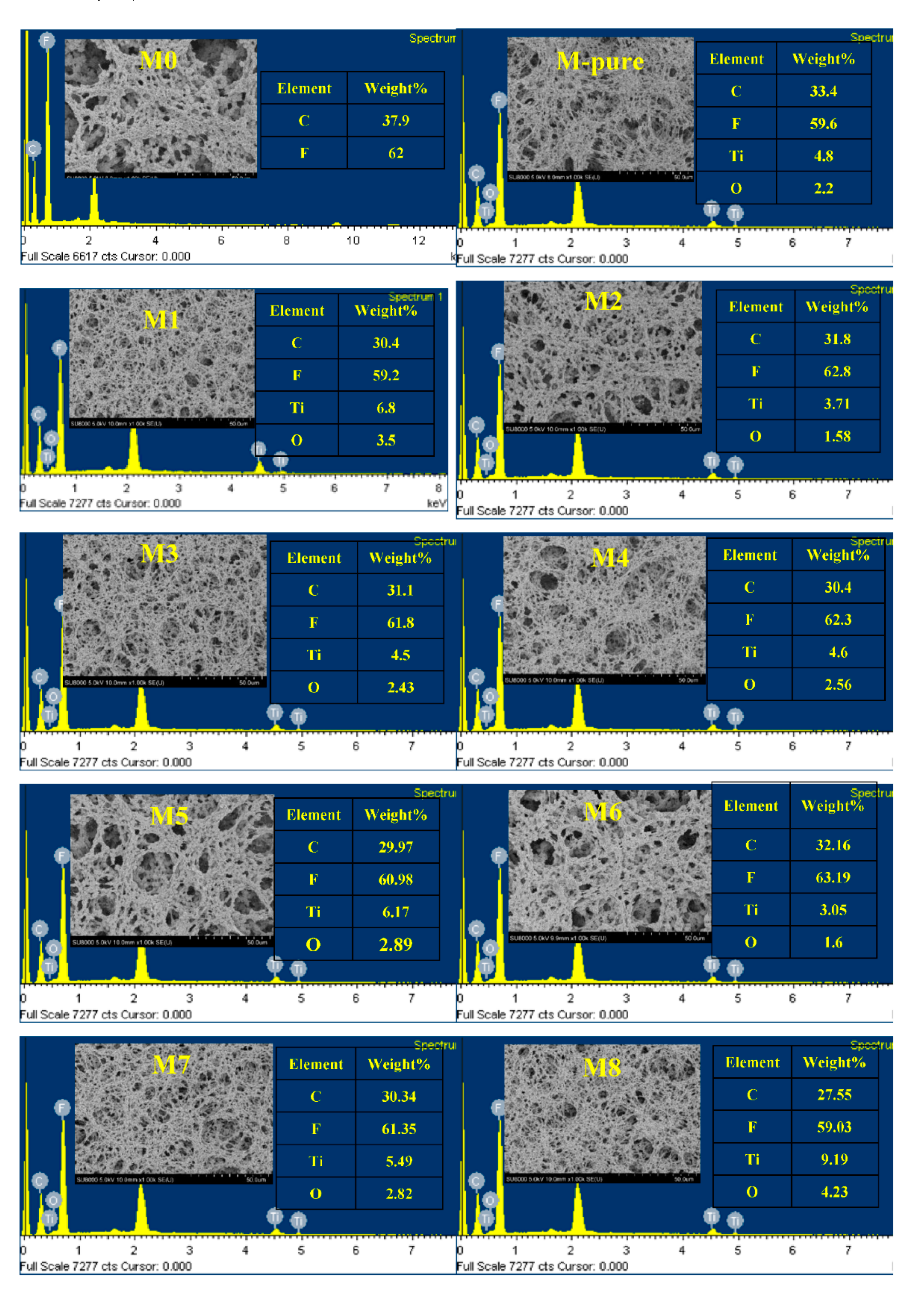
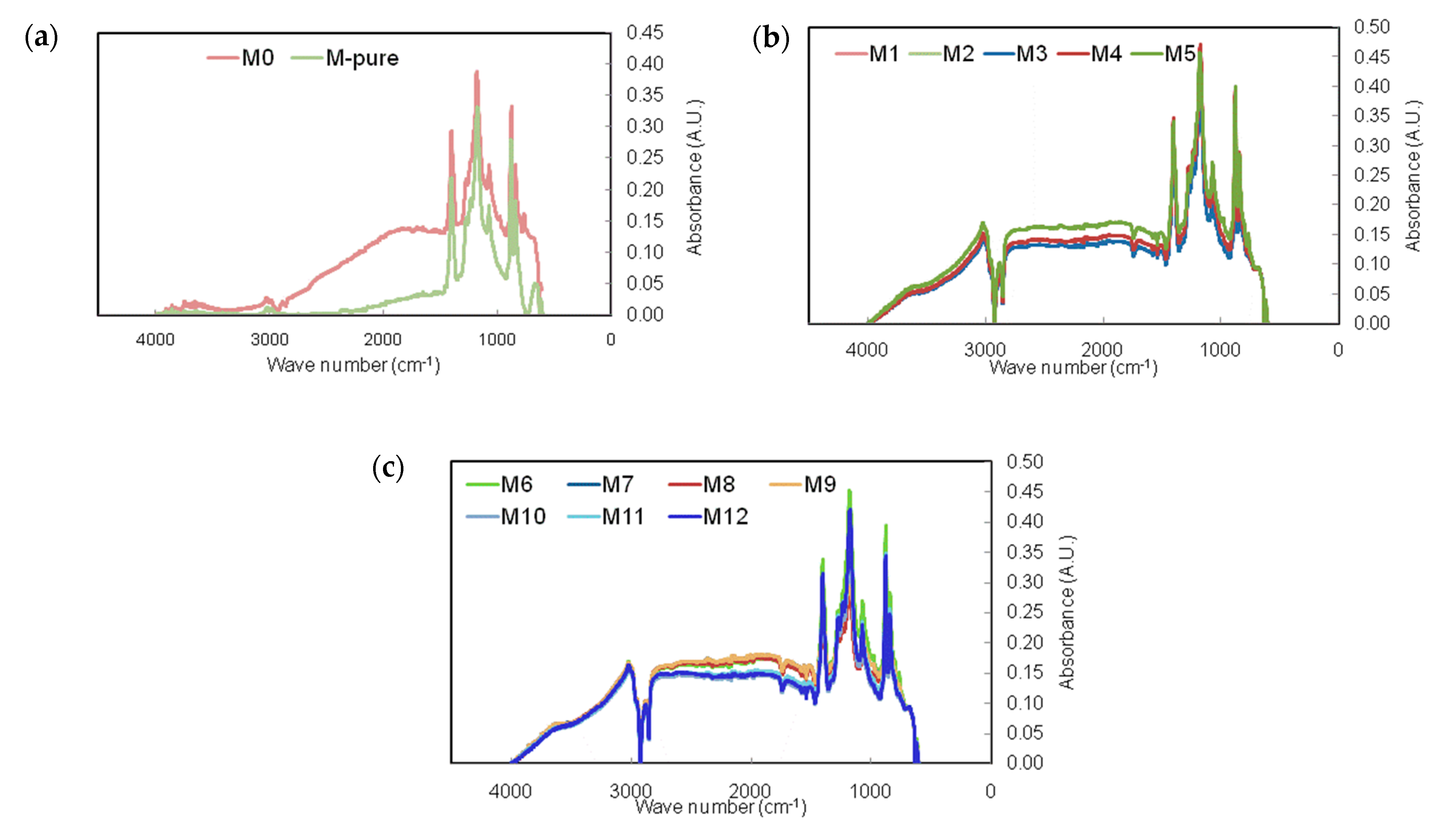
The SEM images of plain views of the membrane in Figure 3 demonstrate that surface morphology of PVDF membrane is similar across the whole membrane. It can be obviously seen that all the prepared membranes showed intrinsically similar features based on plain views by SEM throughout the membrane with an interconnected fibrous structure. We also used NMP wetted support, which is a suitable solvent for PVDF; therefore, the phase inversion can occur in the whole membrane surface, where neat films are cast on a glass plate. It can be seen that the increase in polymer concentration from 14 to 16 wt% exerted a slight effect on membrane surface morphology. Figure 3 also shows the results of SEM–EDX analysis with the elemental composition of the membrane surface. The presence of carbon (C), oxygen (O), fluorine (F) and titanium (Ti) elements detected in these EDX imagesrepresent PVDF polymer and TiO2 nanoparticles in both modified and unmodified membranes.Unlike FT-IR spectra in Figure 4, the existence of silane (Si) in membranes could not be detected by SEM images, so that it might have been embedded in the membrane matrix.
The FTIR spectra showed insignificant changes inPVDF membrane after modification by using different silane and TiO2 concentrations (Figure 4). The amorphous phase of PVDF membrane was represented by the peaks between 840 and 870 cm−1, while the peaks at 1072 cm−1 represent the crystal phase [28]. The bands between 800 and 650 cm−1 proved the existence of TiO2 in the membrane, as also reported by others [26,29].
However, the broad absorbance from 1174 to 1081 cm−1 indicates the formation of Si-O-Ti bonds (and perhaps Si-O-Si bonds). In the spectrum of modified membranes, the bands at 2883 and 3022 cm−1 are assigned to C-H stretching vibration, which corresponds to the presence of silane in modified membranes [28].The band appearing at 1402 cm−1 is due to the C-F stretching vibrations, which confirms that the fluorinated group is successfully grafted on the titania surface.

3.2. Membrane Hydrophobicity

The PVDF membranes were fabricated by introducing TiO2 at different concentrations. Prior to applying TiO2 nanoparticles, they were modified by adding the silane solution to improve membrane hydrophobicity as mentioned above [15]. Contact angle measurements were conducted for each TiO2 concentration. As a result of the high affinity of TiO2 nanoparticles to water, the addition of unmodified TiO2 without silane showed lower membrane hydrophobicity with 84.2° of water contact angle (M-pure) than bare PVDF membrane (97.9°) as shown in Figure 5.
However, hydrophobicity of M-pure could be achieved through the enhancement of surface roughness by adding TiO2 nanoparticles and using ethanol bath for phase inversions [15,16,30]. The surface roughness of this M0, M-pure and M3 was further analyzed using topography images generated by AFM instrument. Three-dimensional images in Figure 6 show that the addition of TiO2 affected surface roughness slightly, but the mean roughness of M3 increased after adding the fluoroalkylsilane.The MD membrane prepared by adding the unmodified TiO2 showed the lowest contact angle in this study. However, when adding the fluoroalkylsilane into TiO2 solution, the hydrophobicity of the membranes prepared was enhanced for all polymer and silane concentrations applied in this study, showing the range of contact angle from 100 to 145.5°(Figure 5). As compared to the contact angle of bare membrane prepared with 15% polymer and 2% TiO2 (M-Pure), adding the 25.7% of silane into TiO2 nanoparticles enhanced the membrane hydrophobicity by 118.3° of contact angle. Furthermore, the effect of TiO2 concentration on the hydrophobicity of the membrane was dependent on the concentration of silane. For two membranes (M11 and M1) prepared at 15 wt% of PVDF concentration and 34.2 wt% of silane concentration, results showed a contact angle of 130.5° and 140.4° for M11 and M1, respectively when increasing TiO2 concentration from 1.5 to 2.5 wt%.
Figure 5 also shows results by contact angle measurements for different polymer concentrations. An increasing polymer concentration increased the contact angle of the membrane surface, supporting the idea that membranes became more hydrophobic at the same silane and TiO2 concentration (M10 and M12). In addition, membrane thickness was increased from 154.6 to 171 µm. This was caused by increased solution viscosity with increasing polymer concentration, which can hinder the penetration of nonsolvent through membrane pore during precipitation step [30,31]. Modified membranes such as M9 and M12 using 2 wt% of TiO2 and 16 wt% of PVDF showed that contact angle increased from 102.8° for M9 to 137.06° for M12, respectively as the silane concentration increased from 17.1 to 34.2 wt%. A similar result was found when comparing the M7 to M11, M8 to M1 and M5 to M10, namely that the contact angle increased with increasing the silane concentration from 17.1 to 34.2 wt% regardless of TiO2 and polymer concentrations. To know the change of contact angle of the membrane after MD experiment, the M1 membrane was selected. It was found that the contact angle was decreased from 140 to 120° after the experiment. More work is still needed to maintain high hydrophobicity of membrane for long-term MD operation.
The silane with fluorinated chains lowers the surface tension of membranes and creates a non-sticking property on membrane surface [32]. In ethanol as used in this study, the silane is hydrolyzed, and hydroxyl groups are formed. Fluorination mainly occurred on the active sites of TiO2 nanoparticles, involving the creation of covalent bonding between hydrolyzed silane and hydroxyl group (OH) of TiO2 nanoparticles within PVDF membrane matrix during the condensation period to allow siloxane networks (Si-O-Si) [16]. The hydroxyl groups in silane can from hydrogen bonding on the active sites of TiO2 nanoparticles where covalent bonding of Si-O-Ti occurs. Finally, TiO-silane complexes are entrapped in the PVDF membrane matrix as shown in Figure 7. This mechanism has been proposed for PVDF-TiO2 composite membrane [16], but more studies are still needed to better understand the formation mechanisms of PVDF membrane entrapped withTiO and silane at various fabricating conditions for MD application. The LEPw values of all modified membranes obtained were retained near to the LEPw of the unmodified membrane. The LEPw of these membranes was not significantly affected by adding TiO2 and silane concentrations but was affected probably by the changes of pore shape besides surface hydrophobicity and pore size as shown in Figure 5 [33].

3.3. Permeate Flux and Ammonium Rejection

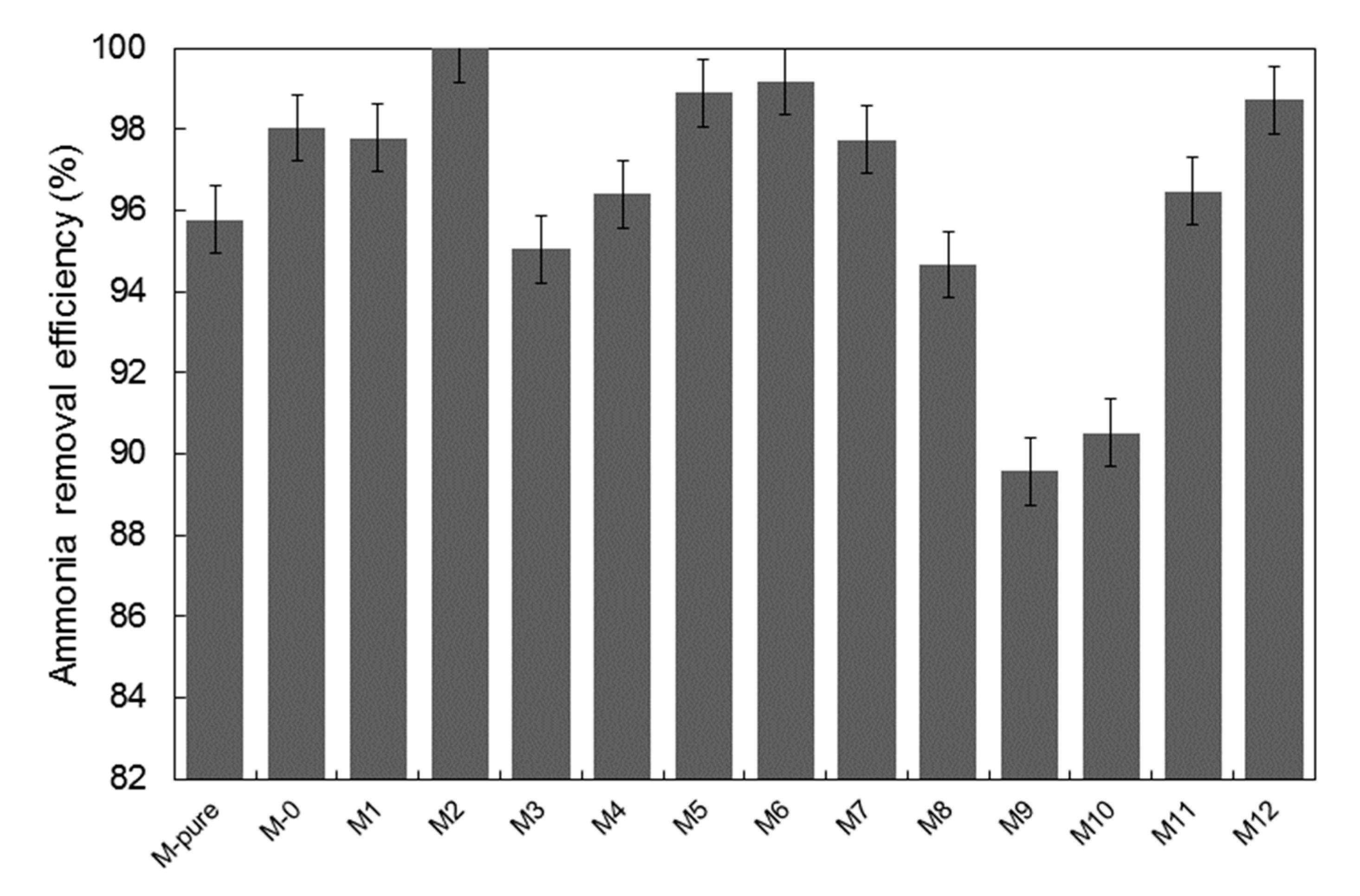
Membrane efficiency in MD operation was evaluated in terms of ammonium rejection and permeate flux. Results are shown in Figure 8 and Figure 9. Despite having a difference in surface membrane characteristics, all the membranes in this study were able to retain 99.9% of ammonium ion. This can be attributed to the fact that the surface hydrophobicity was enhanced, as discussed above, which is crucial to prevent membrane wetting [16]. The variation in membrane porosity seems to affect the ammonium rejection insignificantly, as the surface hydrophobicity may be sufficient enough to prevent ammonia vapor from passing through the membrane to the permeate side. Additionally, higher ammonium rejection could be explained by the cation-exchange capacity of TiO2 to bind the ammonium ion present in feed solution [34,35,36]. It was reported that the titanate-based materials functioned as adsorbent for the removal of ammonium ion due to the interaction between Ti-OH and NH4+, which probably formed the hydrogen bonding [28]. Compared to our previous work, when treating the permeate produced by the staged anaerobic fluidized membrane bioreactor by using a commercial PVDF membrane, the ammonium rejection was around 85%, and this was lower than ammonium rejection achieved by TiO2-PVDF composite membranes fabricated in this study [13].
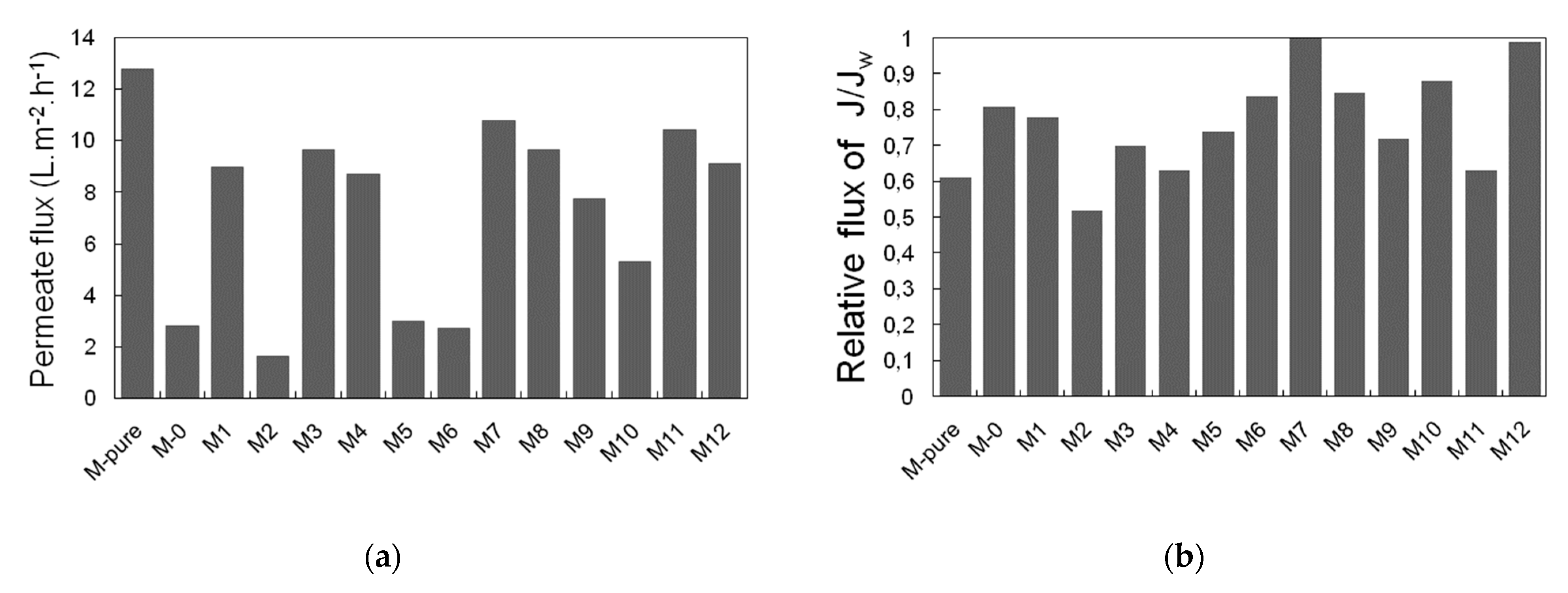
Figure 9 shows permeate flux and relative flux of each membrane synthesized in this study. In Figure 9a, M-pure membrane added with TiO2 only showed higher permeate flux (12.7 L/m2 h) than M0 membrane due to the hydrophilic characteristics of TiO2 [37]. Despite the high porosity of M0 and M5, they provided low permeate flux of 2.83 and 2.99 L/m2 h, probably due to relatively low thickness of these membranes, showing 153 and 156.5 µm, respectively. This is can be explained by the heat loss due to conduction, which tends to decrease the evaporation driving force, thus compromising vapor flux [38]. On the other hand, the membranes prepared at low PVDF concentrations (14 wt%) such as M2, M6 and M10 showed a stable permeate flux ranging 2–5 L/m2 h as compared to the membranes at relatively high PVDF concentration. This can be attributed to the fact that great hydrophobicity induces the formation of less porous structure and prevention of membrane wetting, since the ammonium is not detected in the permeate side [17].
The results of relative flux of each membrane are also shown in Figure 9b. Relative flux represents here the ratio of permeate flux for feed containing pure water to permeate flux for feed containing ammonium chloride after 6 h filtration. Relative flux also represents fouling resistance of the membrane to the feed solution, depending on membrane characteristics and solution composition, which lead to pore wetting and blocking [39]. Most of the membranes showed relative flux within the range of 0.7–1. Nevertheless, the relative flux of M-pure, M2, M4 and M11 was lower than 0.7. This could be related to increment of solute, concentration polarization, temperature polarization and wetting phenomena [23]. Although membrane fouling was observed by using the membranes synthesized in this study, the membrane wetting was not observed significantly after 6 h filtration as very low ammonium concentration was detected in permeate at higher than 90% of rejection efficiency through MD filtration. Therefore, membrane fouling that occurred during the experimental period was thought to contribute to flux decline.

3.4. Application of Response Surface Methodology for Membrane Fabrication

The Box–Behnken model of RSM was employed in these experiments to obtain a quadratic model from 17 sets of experimental runs. The ranges and levels of the three independent variables, i.e., silane, TiO2 and polymer concentrations, are shown in Table 3. F-value tests were performed using an analysis of variance (ANOVA) to calculate the significance of each model employed in the design of expert statistical software. The results for permeate flux (L/m2·h) and ammonium rejection (%) recommended a quadratic model as the highest order polynomial model that satisfies that the model not be aliased. The experimental results obtained for permeate flux (L/m2·h) and ammonium rejection (%) were fitted with the quadratic model, which is represented by Equations (6) and (7), respectively, in terms of coded factors:
YPF (L/m2·h) = 10.25 + 0.20A− 0.08B + 2.92C − 0.33AB − 0.25AC + 0.17BC − 0.07A2 − 0.47B2 − 3.90C2
YAR (%) = 95.91 + 0.33A − 0.04B − 0.65C + 1.10AB + 4.38AC + 0.77BC − 1.69A2 + 2.44B2 + 0.21C2
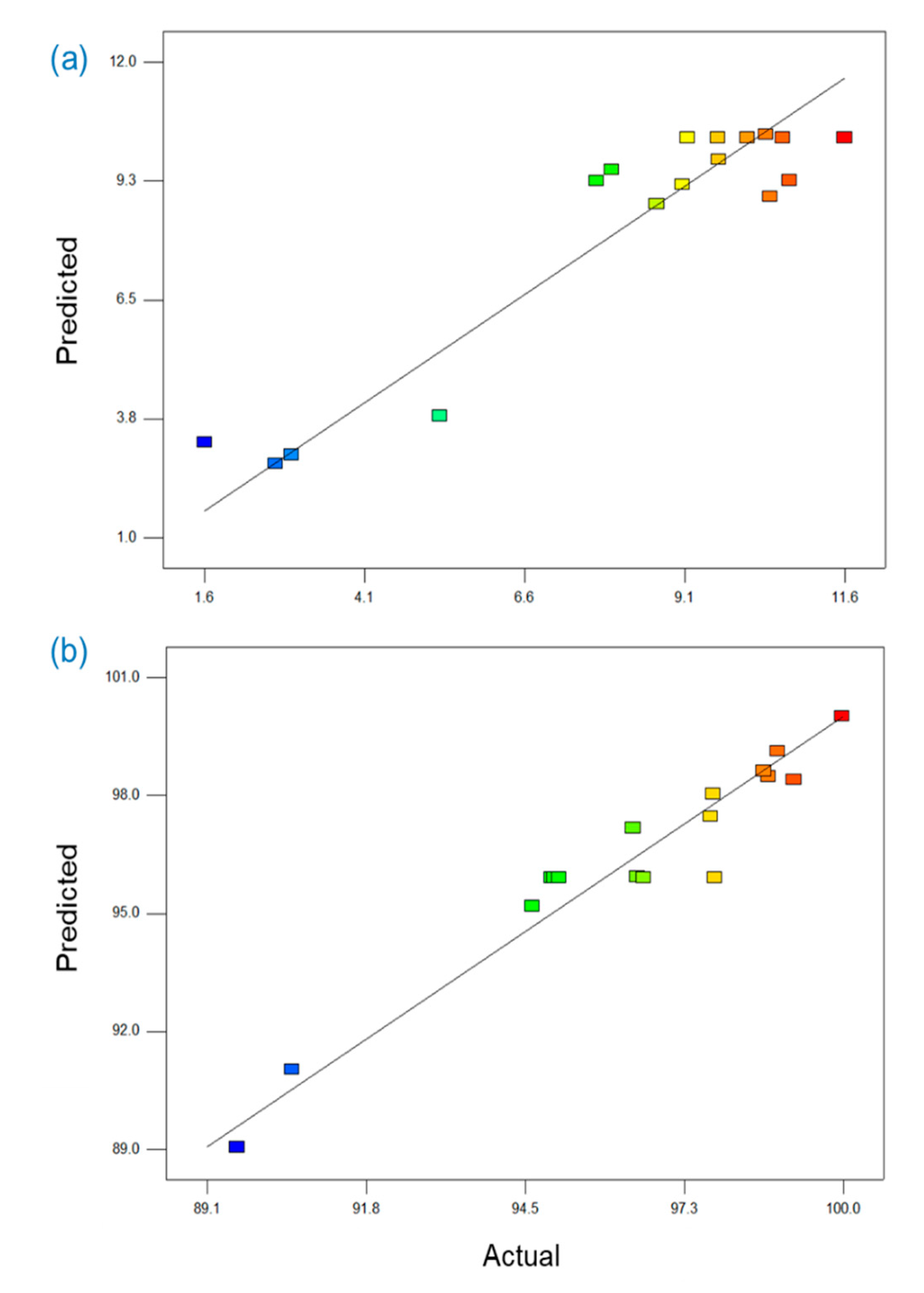
The significance of the values of the model equations for permeate flux and ammonium rejection were checked by F, R2, adjusted R2, lack-of-fitand adequate precision tests. In the case of the permeate flux, as shown in Table 4, the model F-value, which was calculated by dividing the mean squares of each variable effect by the mean square, was 5.972, and the low probability value (0.0140), which was less than p-value at the 95% confidence limit, verified that the model terms were significant. The model probability value (0.0023) for ammonium rejection was also low enough to confirm that the model terms for ammonium rejection were significant. The goodness-of-fit of each model was also tested via the correlation coefficient R2, and the R2 values for the permeate flux and ammonium rejection were 0.885 and 0.934, respectively, indicating that both were reasonably close to 1 and thus acceptable. The adjusted R2 values for permeate flux and ammonium rejection were 0.737 and 0.848, respectively, and both values were statistically reasonable. Lack-of-fit tests were also used to evaluate the model adequacy; an insignificant lack-of-fit is desired [19,40]. The lack-of-fit values for permeate flux and ammonium rejection were 0.731 and 0.680, respectively; these values were statistically insignificant and showed that the constructed models were suitable to describe the observed data. The values of adequate precision, which reflected the signal-to-noise ratio, were 6.24 and 12.74 for permeate flux and ammonium rejection, respectively; because these values were greater than 4, they indicated adequate signals. Figure 10 shows that the points of the predicted versus actual plots for permeate flux and ammonium rejection are clustered along a diagonal line, indicating that the predicted values match well with the observed ones.
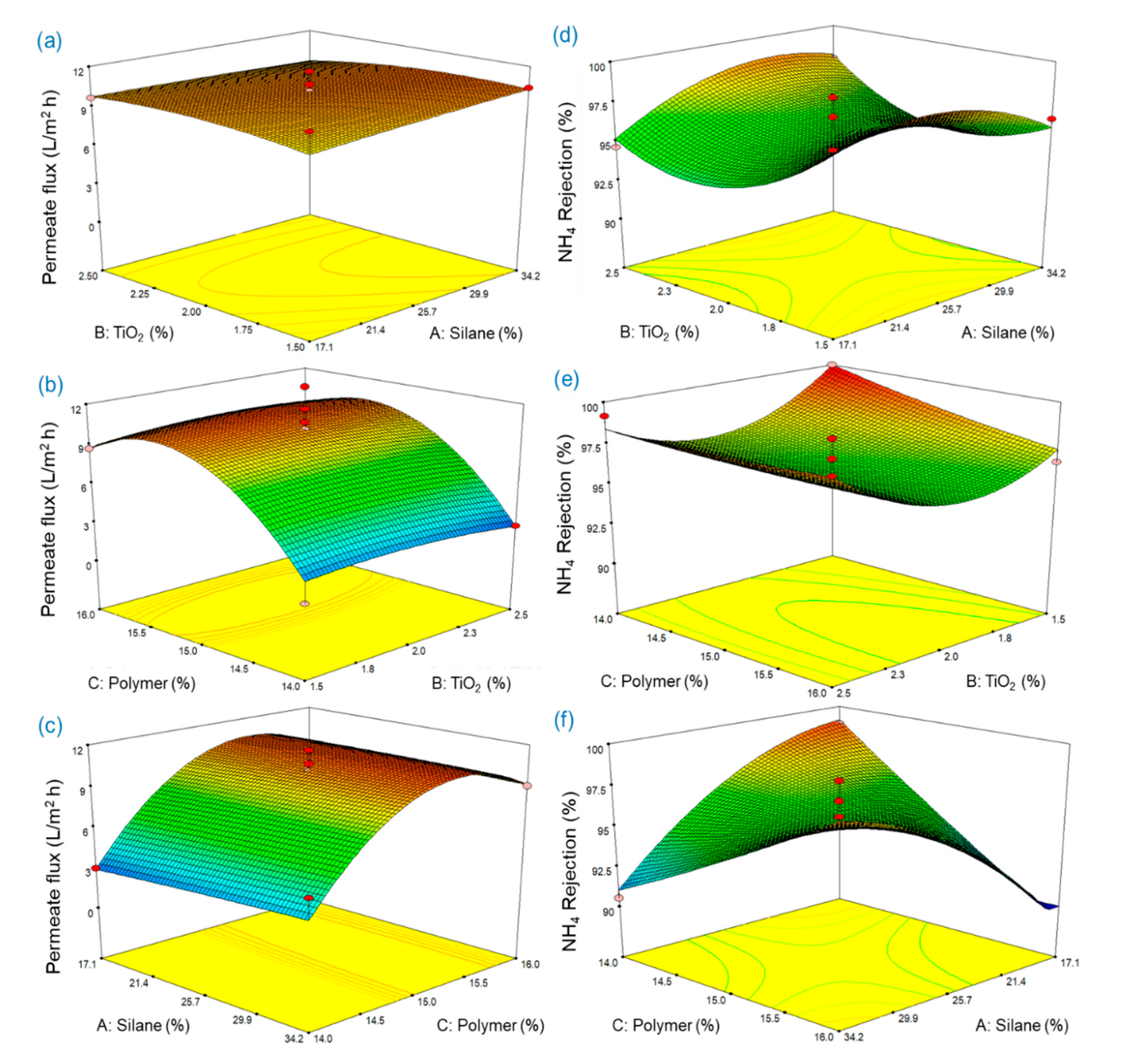
Table 4 shows that the significance of each term was determined by a p-value (Prob > F) less than 0.05 and that the linear and quadratic of polymer concentration significantly influenced the permeate flux. In Equation (6), a positive value for C indicates that the increase of polymer concentration has a positive effect on the permeate flux. However, a negative coefficient of C2 indicates that the permeate flux became lower at a higher polymer concentration. As shown in Figure 11, the permeate flux was increased as the polymer concentration increasedfrom 14.0 to 15.5%, but it was slightly decreased as the polymer concentration increased from 15.5 to 16.0%. In the case of ammonium rejection, AC, A2, and B2 were found to be significant factors influencing on the ammonia rejection of the synthesized membrane in this study. The interactive effects of silane and polymer concentrations on the ammonium rejection weresignificant, and the positive coefficient of AC indicated that the ammonium rejection was proportional to the product of silane and polymer concentration. The p-values of A2 and B2 were significant, but those of A and B were insignificant, indicating that the impact of silane and TiO2 at its highest value should be significant. The p-values more than 0.05 for C and C2 showed that the influence of polymer concentration on ammonium rejection was not statistically significant, which was in contrast to the results for permeate flux.
To obtain optimum conditions, the desired values for each input and response factor can be selected using numerical optimization. The optimum conditions to maximize the responses, i.e., permeate flux and ammonium rejection, were calculated by statistical software. The highest permeate flux of 10.91 L/m2·h was obtained at 34.2% of silane concentration, 1.81% of TiO2 concentration and 15.33% of polymer concentration, and the maximum ammonium rejection of the synthesized membrane obtained from the RSM model was 100.4% at 24.8% of silane concentration, 1.50% of TiO2 concentration, and 14.01% of polymer concentration. Maximized permeate flux and ammonium rejection simultaneously were 10.10 L/m2·h and 100.0%, respectively, which were not significantly different from those obtained by optimizing each value. The conditions for obtaining both highest permeate flux and highest ammonium rejection were 31.3% of silane concentration, 2.50% of TiO2 concentration, and 15.48% of polymer concentration.

4. Conclusions

PVDF membranes were successfully synthesized by embedding TiO2 modified by silane to improve ammonia rejection and permeate flux in MD application. Membrane porosity decreased with increasing polymer concentration. Embedding TiO2 into the PVDF membrane improved hydrophilicity, but this effectiveness was less pronounced as silane concentration was higher. Increasing silane concentration enhanced membrane hydrophobicity but also reduced membrane porosity. The membrane synthesized provided the permeate flux ranging from 5.3 to 10.8 L/m2·h, with more than 90% of ammonia rejection efficiency. Highest ammonium rejection was associated with the highest membrane hydrophobicity since membrane wetting could be prevented by hydrophobic membrane surface by adding the TiO2 and silane. RSM analysis was found to be a useful way to determine optimized conditions to fabricate the PVDF-TiO2 composite membrane for enhancing both ammonia rejection efficiency and permeate flux in MD filtration. Due to the high retention propensity of MD membrane synthesized with inorganic contaminant such as ammonium ion as observed in this study, integrating anaerobic membrane bioreactor where nitrogen removal is very limited with an MD process may be proposed for energy-saving, wastewater reclamation. It can be also proposed that the nutrients produced by the anaerobic process can be concentrated directly by the MD membrane for future resource recovery.

Supplementary Materials

The following are available online at https://www.mdpi.com/2077-0375/11/2/95/s1, Figure S1: SEM images of PVDF membranes prepared at different polymer, TiO2 and silane concentrations.

Author Contributions

F.T.; Methodology, investigation, writing—original draft, S.-J.P.; methodology, investigation, writing—original draft, J.K.; conceptualization, investigation, review and editing, project administration, supervision and funding acquisition. All authors have read and agreed to the published version of the manuscript.

Funding

This research was funded by the National Research Foundation of Korea (NRF) grant funded by the Korea government (MSIT) (NRF-2017R1A2B4007804).

Conflicts of Interest

The authors declare no conflict of interest.

References

  1. Bae, T.-H.; Tak, T.-M. Effect of TiO2 nanoparticles on fouling mitigation of ultrafiltration membranes for activated sludge filtration. J. Membr. Sci. 2005, 249, 1–8. [Google Scholar] [CrossRef]
  2. Cao, X.; Ma, J.; Shi, X.; Ren, Z. Effect of TiO2 nanoparticle size on the performance of PVDF membrane. Appl. Surf. Sci. 2006, 253, 2003–2010. [Google Scholar] [CrossRef]
  3. Diebold, U. The surface science of titanium dioxide. Surf. Sci. Rep. 2003, 48, 53–229. [Google Scholar] [CrossRef]
  4. Huo, R.; Gu, Z.; Zuo, K.; Zhao, G. Preparation and properties of PVDF-fabric composite membrane for membrane distillation. Desalination 2009, 249, 910–913. [Google Scholar] [CrossRef]
  5. Tang, Y.; Li, N.; Liu, A.; Ding, S.; Yi, C.; Liu, H. Effect of spinning conditions on the structure and performance of hydrophobic PVDF hollow fiber membranes for membrane distillation. Desalination 2012, 287, 326–339. [Google Scholar] [CrossRef]
  6. Meyer, E.E.; Rosenberg, K.J.; Israelachvili, J. Recent progress in understanding hydrophobic interactions. Proc. Natl. Acad. Sci. USA 2006, 103, 15739–15746. [Google Scholar] [CrossRef] [Green Version]
  7. Meng, S.; Ye, Y.; Mansouri, J.; Chen, V. Fouling and crystallisation behaviour of superhydrophobic nano-composite PVDF membranes in direct contact membrane distillation. J. Membr. Sci. 2014, 463, 102–112. [Google Scholar] [CrossRef]
  8. Zuo, G.; Wang, R. Novel membrane surface modification to enhance anti-oil fouling property for membrane distillation application. J. Membr. Sci. 2013, 447, 26–35. [Google Scholar] [CrossRef]
  9. Ou, J.; Hu, W.; Xue, M.; Wang, F.; Li, W. One-step solution immersion process to fabricate superhydrophobic surfaces on light alloys. ACS Appl. Mater. Interfaces 2013, 5, 9867–9871. [Google Scholar] [CrossRef]
  10. El-Abbassi, A.; Khayet, M.; Kiai, H.; Hafidi, A.; García-Payo, M.C. Treatment of crude olive mill wastewaters by osmotic distillation and osmotic membrane distillation. Sep. Purif. Technol. 2013, 104, 327–332. [Google Scholar] [CrossRef]
  11. El-Abbassi, A.; Hafidi, A.; Khayet, M.; García-Payo, M.C. Integrated direct contact membrane distillation for olive mill wastewater treatment. Desalination 2013, 323, 31–38. [Google Scholar] [CrossRef]
  12. Kiai, H.; García-Payo, M.; Hafidi, A.; Khayet, M. Application of membrane distillation technology in the treatment of table olive wastewaters for phenolic compounds concentration and high quality water production. Chem. Eng. Process. Process Intensif. 2014, 86, 153–161. [Google Scholar] [CrossRef]
  13. Tibi, F.; Guo, J.; Ahmad, R.; Lim, M.; Kim, M.; Kim, J. Membrane distillation as post-treatment for anaerobic fluidized bed membrane bioreactor for organic and nitrogen removal. Chemosphere 2019, 234, 756–762. [Google Scholar] [CrossRef]
  14. Lafuma, A.; Quéré, D. Superhydrophobic states. Nat. Mater. 2003, 2, 457–460. [Google Scholar] [CrossRef]
  15. Ma, J.; Wang, Z.; Pan, M.; Guo, Y. A study on the multifunction of ferrous chloride in the formation of poly (vinylidene fluoride) ultrafiltration membranes. J. Membr. Sci. 2009, 341, 214–224. [Google Scholar] [CrossRef]
  16. Razmjou, A.; Arifin, E.; Dong, G.; Mansouri, J.; Chen, V. Superhydrophobic modification of TiO2 nanocomposite PVDF membranes for applications in membrane distillation. J. Membr. Sci. 2012, 415, 850–863. [Google Scholar] [CrossRef]
  17. Hamzah, N.; Leo, C.P. Membrane distillation of saline with phenolic compound using superhydrophobic PVDF membrane incorporated with TiO2 nanoparticles: Separation, fouling and self-cleaning evaluation. Desalination 2017, 418, 79–88. [Google Scholar] [CrossRef]
  18. Khayet, M.; Seman, M.A.; Hilal, N. Response surface modeling and optimization of composite nanofiltration modified membranes. J. Membr. Sci. 2010, 349, 113–122. [Google Scholar]
  19. Park, S.-J.; An, H.-K. Optimization of fabrication parameters for nanofibrous composite membrane using response surface methodology. Desalination Water Treat. 2016, 57, 20188–20198. [Google Scholar] [CrossRef]
  20. Efome, J.E.; Rana, D.; Matsuura, T.; Lan, C.Q. Enhanced performance of PVDF nanocomposite membrane by nanofiber coating: A membrane for sustainable desalination through MD. Water Res. 2016, 89, 39–49. [Google Scholar] [CrossRef]
  21. Wu, C.; Tang, W.; Zhang, J.; Liu, S.; Wang, Z.; Wang, X.; Lu, X. Preparation of super-hydrophobic PVDF membrane for MD purpose via hydroxyl induced crystallization-phase inversion. J. Membr. Sci. 2017, 543, 288–300. [Google Scholar] [CrossRef]
  22. Xu, Z.; Liu, Z.; Song, P.; Xiao, C. Fabrication of super-hydrophobic polypropylene hollow fiber membrane and its application in membrane distillation. Desalination 2017, 414, 10–17. [Google Scholar] [CrossRef]
  23. Hamzah, N.; Leo, C.P. Fouling prevention in the membrane distillation of phenolic-rich solution using superhydrophobic PVDF membrane incorporated with TiO2 nanoparticles. Sep. Purif. Technol. 2016, 167, 79–87. [Google Scholar] [CrossRef]
  24. Zuo, J.; Bonyadi, S.; Chung, T.-S. Exploring the potential of commercial polyethylene membranes for desalination by membrane distillation. J. Membr. Sci. 2016, 497, 239–247. [Google Scholar] [CrossRef]
  25. Pu, W.; He, X.; Wang, L.; Jiang, C.; Wan, C. Preparation of PVDF–HFP microporous membrane for Li-ion batteries by phase inversion. J. Membr. Sci. 2006, 272, 11–14. [Google Scholar] [CrossRef]
  26. Freger, V.; Gilron, J.; Belfer, S. TFC polyamide membranes modified by grafting of hydrophilic polymers: An FT-IR/AFM/TEM study. J. Membr. Sci. 2002, 209, 283–292. [Google Scholar] [CrossRef]
  27. Rezaei, M.; Ismail, A.; Bakeri, G.; Hashemifard, S.; Matsuura, T. Effect of general montmorillonite and Cloisite 15A on structural parameters and performance of mixed matrix membranes contactor for CO2 absorption. Chem. Eng. J. 2015, 260, 875–885. [Google Scholar] [CrossRef]
  28. Zhang, J.; Song, Z.; Li, B.; Wang, Q.; Wang, S. Fabrication and characterization of superhydrophobic poly (vinylidene fluoride) membrane for direct contact membrane distillation. Desalination 2013, 324, 1–9. [Google Scholar] [CrossRef]
  29. Cruz, N.K.O.; Semblante, G.U.; Senoro, D.B.; You, S.-J.; Lu, S.-C. Dye degradation and antifouling properties of polyvinylidene fluoride/titanium oxide membrane prepared by sol–gel method. J. Taiwan Inst. Chem. Eng. 2014, 45, 192–201. [Google Scholar] [CrossRef]
  30. Hou, D.; Fan, H.; Jiang, Q.; Wang, J.; Zhang, X. Preparation and characterization of PVDF flat-sheet membranes for direct contact membrane distillation. Sep. Purif. Technol. 2014, 135, 211–222. [Google Scholar] [CrossRef]
  31. Fadhil, S.; Marino, T.; Makki, H.F.; Alsalhy, Q.F.; Blefari, S.; Macedonio, F.; Nicolò, E.D.; Giorno, L.; Drioli, E.; Figoli, A. Novel PVDF-HFP flat sheet membranes prepared by triethyl phosphate (TEP) solvent for direct contact membrane distillation. Chem. Eng. Process. Process Intensif. 2016, 102, 16–26. [Google Scholar] [CrossRef]
  32. Yang, C.; Li, X.-M.; Gilron, J.; Kong, D.-f.; Yin, Y.; Oren, Y.; Linder, C.; He, T. CF4 plasma-modified superhydrophobic PVDF membranes for direct contact membrane distillation. J. Membr. Sci. 2014, 456, 155–161. [Google Scholar] [CrossRef]
  33. García-Payo, M.C.; Izquierdo-Gil, M.A.; Fernández-Pineda, C. Wetting Study of Hydrophobic Membranes via Liquid Entry Pressure Measurements with Aqueous Alcohol Solutions. J. Colloid Interface Sci. 2000, 230, 420–431. [Google Scholar] [CrossRef] [PubMed]
  34. Lin, C.-H.; Wong, D.S.-H.; Lu, S.-Y. Layered Protonated Titanate Nanosheets Synthesized with a Simple One-Step, Low-Temperature, Urea-Modulated Method as an Effective Pollutant Adsorbent. ACS Appl. Mater. Interfaces 2014, 6, 16669–16678. [Google Scholar] [CrossRef]
  35. Liu, W.; Sun, W.; Han, Y.; Ahmad, M.; Ni, J. Adsorption of Cu(II) and Cd(II) on titanate nanomaterials synthesized via hydrothermal method under different NaOH concentrations: Role of sodium content. Colloids Surf. A Physicochem. Eng. Asp. 2014, 452, 138–147. [Google Scholar] [CrossRef]
  36. Ye, M.; Lu, Z.; Hu, Y.; Zhang, Q.; Yin, Y. Mesoporous titanate-based cation exchanger for efficient removal of metal cations. J. Mater. Chem. 2013, 1, 5097–5104. [Google Scholar] [CrossRef]
  37. Wei, Y.; Chu, H.-Q.; Dong, B.-Z.; Li, X.; Xia, S.-J.; Qiang, Z.-M. Effect of TiO2 nanowire addition on PVDF ultrafiltration membrane performance. Desalination 2011, 272, 90–97. [Google Scholar] [CrossRef]
  38. Kim, H.; Noh, K.; Choi, C.; Khamwannah, J.; Villwock, D.; Jin, S. Extreme Superomniphobicity of Multiwalled 8 nm TiO2 Nanotubes. Langmuir 2011, 27, 10191–10196. [Google Scholar] [CrossRef]
  39. Bakeri, G.; Matsuura, T.; Ismail, A.F.; Rana, D. A novel surface modified polyetherimide hollow fiber membrane for gas–liquid contacting processes. Sep. Purif. Technol. 2012, 89, 160–170. [Google Scholar] [CrossRef]
  40. Nemeth, M.A. Response Surface Methodology: Process and Product Optimization Using Designed Experiments. J. Qual. Technol. 2003, 35, 428–429. [Google Scholar] [CrossRef]
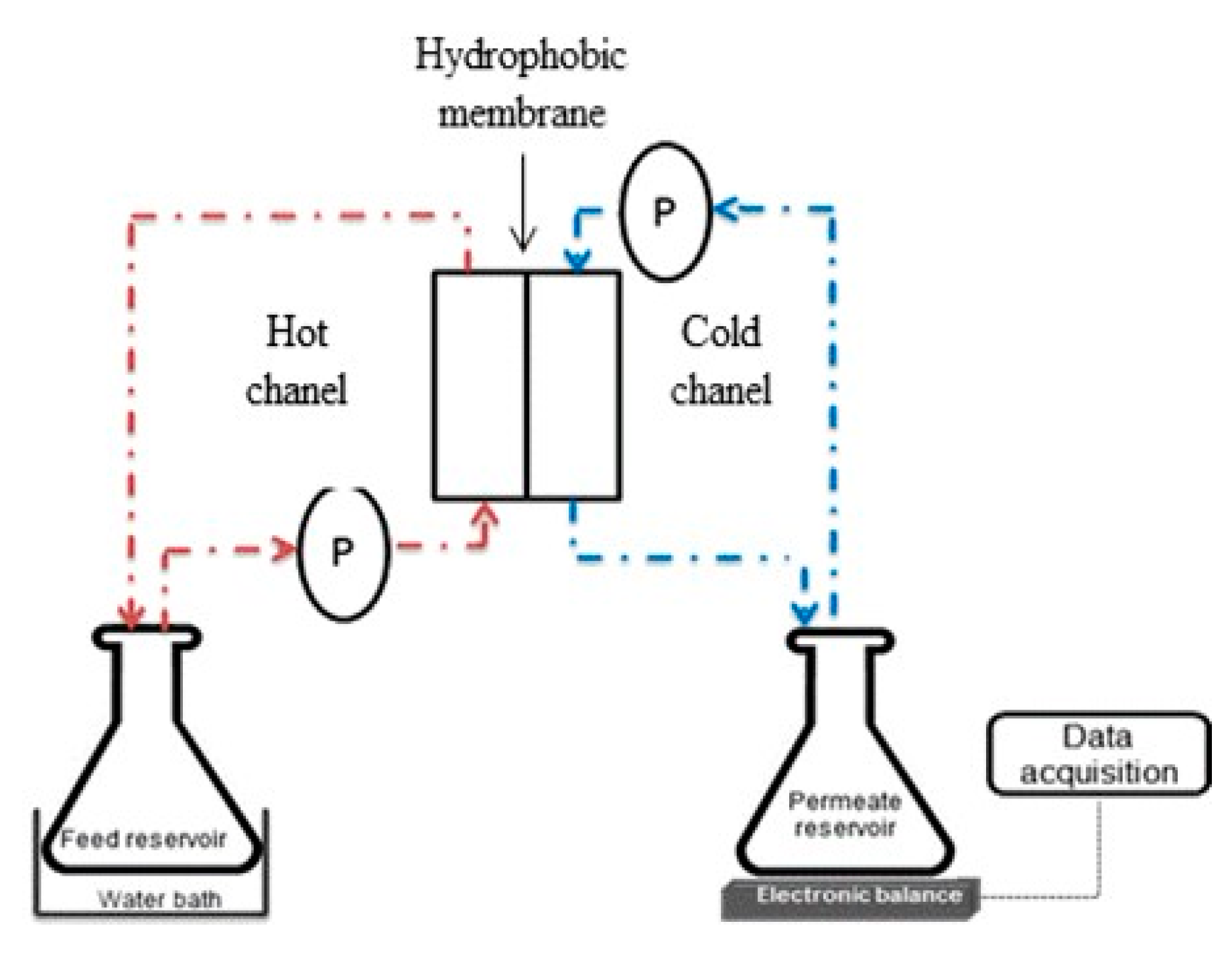
Figure 1. Experimental set-up of direct-contact membranedistillation(DCMD).
Membranes 11 00095 g001
Figure 2. (a) The effect of TiO2 concentrationon membrane porosity and (b) combined effect of TiO2 and silane dosage on membrane porosity.
Membranes 11 00095 g002
Figure 3. SEM-EDX analysis of PVDF membranes prepared at different polymer, TiO2 and silane concentrations.
Membranes 11 00095 g003aMembranes 11 00095 g003b
Figure 4. FT-IR spectra of the PVDF membranes before and after silane modification.
Membranes 11 00095 g004
Figure 5. Contact angle of synthesized membranes.
Membranes 11 00095 g005
Figure 6. AFM images of M0, M-pure and M3 membranes.
Membranes 11 00095 g006
Figure 7. Schematic representation of silanization of the PVDF membranes: (a) hydrolysationof trichloro (1H, 1H, 2H, 2H-heptadecafluorodecyl) silane; (b) condensation and formation of siloxane networks via covalent bonding; (c) interaction with the surface of TiO2; (d) incorporation of modified TiO2 in PVDF dope solution.
Membranes 11 00095 g007
Figure 8. Removal efficiency of ammonium nitrogen of membranes synthesized.
Membranes 11 00095 g008
Figure 9. (a) Permeate flux variation of synthesized membrane treating ammonia chloride as feed solution and (b) relative flux of membrane after filtration.
Membranes 11 00095 g009
Figure 10. Plot of predicted values versus actual values for (a) permeate flux (L/m2·h) and (b) ammonium rejection (%).
Membranes 11 00095 g010
Figure 11. Estimated response surface for permeate flux (L/m2·h) showing the influence of (a) silane and TiO2 concentrations, (b) TiO2 and polymer concentrations and (c) polymer and silane concentrations. Estimated response surface for ammonium rejection (%) showing the influence of (d) silane and TiO2 concentrations, (e) TiO2 and polymer concentrations and (f) polymer and silane.
Membranes 11 00095 g011
Table 1. Membrane properties and processing parameters for MD application in previous studies.
MembranePropertiesProcessing ParametersPreparationRef
PVDF membrane with superhydrophobic TiO2θ:160
ε:38–46;
d:0.34–0.44
Feed: 100 g/LGA + 50 g/L NaCl;
Tf: 40 °C, Tp: 20°C, Q: 300 mL/min
Phase Inversion[17]
PVDF membrane with superhydrophobic SiO2θ:139 ± 5
d:0.45
Feed: 3.5 wt%NaCl
Tf: 27.5°C, Tp:15°C, Q: 2000 mL/min
Electrospinning[20]
PVDF membrane with SiO2θ:153
ε:79.24; d:0.1
Feed: 3.5 wt%NaCl
Tf: 70 °C, Tp: 15 °C; Q: 3000 mL/min
Phase Inversion[21]
PP membrane with SiO2θ:157
ε:47.63
Feed: 3.5 wt%NaCl;
Tf: 80 °C
Phase Inversion[22]
PVDFmembranewith superhydrophobic TiO2θ:151.9 ± 1.5
ε:30.3 ± 3.9;
d:0.37
Feed: 100 g/LGA + 50 g/L NaCl;
Tf: 40 °C, Tp: 20; Q: 300 mL/min
Phase Inversion[23]
PVDF membrane with superhydrophobic TiO2θ:140 ± 2°
ε:73%
Feed: 35 mg/L NH4Cl;
Tf: 60 °C, Tp: 25 °C; Q: 500 mL/min
Phase InversionThis study
Commercial PE membraneθ: 108.3 ± 3
ε: 66.1 ± 7.2;
d: 0.2
Feed: 3.5 wt% NaCl;
Tf: 80 °C, Tp:17 °C;Q: 400 mL/min
Phase Inversion by TIPS[24]
Commercial PVDF membraneθ:111
d:0.22
Feed: AFMBR permeate (35 mg/L TN + 27 mg/L COD)
Tf: 60 °C, Tp: 25 °C; Q: 500 mL/min
[13]
Note: θ: Contact angle (°); ε:Porosity (%); d: pore size (µm); Tf: Feed temperature (°C); Tp: Permeate temperature (°C); Q: Flow rate (mL/min).
Table 2. Combinations of fabricating conditions for PVDF composite membrane.
MembranesSilane (w/w%)TiO2 (wt%)PVDF (wt%)Porosity (%)Contact Angle (°)Thickness
(µm)
M-pure021579.784.2159.0
M0001583.297.9153.0
M134.22.51573.0140.0155.0
M225.651.51462.1144.6159.3
M325.6521577.2118.2173.5
M425.651.51666.8143.8164.0
M517.121467.8111.4156.5
M625.652.51466.3145.4146.3
M717.11.51576.6108.4155.0
M817.12.51575.9138.5149.3
M917.121652.1102.8170.3
M1034.221464.4130.7154.6
M1134.21.51581.7130.5159.3
M1234.221663.8137.0171.0
Table 3. Coded and actual values of variables for the experiment.
VariablesSymbolCoded Factor Level
−101
Silane (wt%)A17.125.6534.2
TiO2 (wt%)B1.52.02.5
Polymer (wt%)C141516
Table 4. Summary of ANOVA for response surface quadratic model of permeate flux and ammonium rejection. Underline indicates that p-value is less than 0.05.
SourcePermeate FluxAmmonium Rejection
Sum of SquaresdfMean SquareF Valuep-Value
Prob > F
Sum of SquaresdfMean SquareF Valuep-Value
Prob > F
Model135.65915.075.9720.0140123.89913.7710.940.0023
A-Silane0.3310.330.1300.72910.8810.880.700.4312
B-TiO20.0510.050.0200.89080.0110.010.010.9177
C-Polymer68.21168.2127.0270.00133.4213.422.720.1433
AB0.4210.420.1670.69474.8014.803.810.0918
AC0.2410.240.0950.766776.83176.8361.060.0001
BC0.1110.110.0430.84142.3712.371.880.2121
A20.0210.020.0070.933512.01112.019.540.0176
B20.9410.940.3720.561425.04125.0419.900.0029
C263.94163.9425.3360.00150.1810.180.140.7171
Residual17.6772.52 8.8171.26
Lack-of-fit14.0534.685.1770.07312.5430.850.540.6799
Pure Error3.6240.90 6.2741.57
Cor Total153.3116 132.6916
Publisher’s Note: MDPI stays neutral with regard to jurisdictional claims in published maps and institutional affiliations.