Article

Layer-by-Layer Heterostructure of MnO2@Reduced Graphene Oxide Composites as High-Performance Electrodes for Supercapacitors

1
Qinhuangdao Key Laboratory of Marine Oil and Gas Resource Exploitation and Pollution Prevention, Northeast Petroleum University at Qinhuangdao, Qinhuangdao 066004, China
2
Provincial Key Laboratory of Polyolefin New Materials, College of Chemistry & Chemical Engineering, Northeast Petroleum University, Daqing 163318, China
3
Hebei Key Laboratory of Applied Chemistry, College of Environmental and Chemical Engineering, Yanshan University, Qinhuangdao 066004, China
*
Authors to whom correspondence should be addressed.
Membranes 2022, 12(11), 1044; https://doi.org/10.3390/membranes12111044
Submission received: 20 September 2022 / Revised: 22 October 2022 / Accepted: 23 October 2022 / Published: 26 October 2022

Abstract

:
In this paper, δ-MnO2 with layered structure was prepared by a facile liquid phase method, and exfoliated MnO2 nanosheet (e-MnO2) was obtained by ultrasonic exfoliation, whose surface was negatively charged. Then, positive charges were grafted on the surface of MnO2 nanosheets with a polycation electrolyte of polydiallyl dimethylammonium chloride (PDDA) in different concentrations. A series of e-MnO2@reduced graphene oxide (rGO) composites were obtained by electrostatic self-assembly combined with hydrothermal chemical reduction. When PDDA was adjusted to 0.75 g/L, the thickness of e-MnO2 was ~1.2 nm, and the nanosheets were uniformly adsorbed on the surface of graphene, which shows layer-by-layer morphology with a specific surface area of ~154 m2/g. On account of the unique heterostructure, the composite exhibits good electrochemical performance as supercapacitor electrodes. The specific capacitance of e-MnO2-0.75@rGO can reach 456 F/g at a current density of 1 A/g in KOH electrolyte, which still remains 201 F/g at 10 A/g. In addition, the capacitance retention is 98.7% after 10000 charge-discharge cycles at 20 A/g. Furthermore, an asymmetric supercapacitor (ASC) device of e-MnO2-0.75@rGO//graphene hydrogel (GH) was assembled, of which the specific capacitance achieves 94 F/g (1 A/g) and the cycle stability is excellent, with a retention rate of 99.3% over 10000 cycles (20 A/g).

1. Introduction

Under the background of rapid global economic development, continuous consumption of fossil energy, and increasingly serious environmental pollution, seeking “green” and renewable energy has become the most urgent challenge in society nowadays. Moreover, the breakthrough and popularization of large-scale energy storage technology is strong support for the development of renewable energy. In many forms of energy storage, electrochemical energy storage (EES) has been highly focused on because of its high theoretical conversion efficiency of chemical energy to electrical energy, as well as the high energy density and power density. Accordingly, further technological innovation requires continuous improvement of performance, which also drives the researchers’ exploration of new materials and mechanisms. Compared to batteries, supercapacitors can offer higher power densities and have longer cycle life, faster charge-discharge capabilities and better safety. Therefore, the application of supercapacitors in the field of energy storage has attracted wide attention [1,2].
According to the mechanism of charge storage, supercapacitors can be divided into electrical double-layer capacitors (EDLC) and pseudocapacitors. The electrode materials of EDLC are mainly based on carbon materials, such as activated carbon (AC) [3], carbon nanotube (CNTs) [4,5,6], and graphene [7,8]. For pseudocapacitors, a variety of different materials, such as metal oxides [9,10,11] or hydroxides [12,13], conductive polymers [14,15] and metal sulfides [16], are all candidates for electrode materials. As the first pseudocapacitance electrode material, RuO2 has excellent electrochemical performance [17]. However, the toxicity and high cost limit its large-scale application [18]. Some transition metal oxides with low cost also exhibit pseudocapacitive behaviors and can be used in supercapacitors instead of RuO2, such as MnO2. However, due to poor electronic conductivity, charge storage is limited to a thin layer on the surface, resulting in much lower actual capacitance than its theoretical value. In addition, low charge transfer kinetics and slow ion diffusion also affect the rate performance [19,20]. The effective strategies to improve the electrochemical performance are to increase the specific surface area of the materials by designing various nanostructures to increase the active sites or to construct hierarchical porous structures to improve mass transfer [18]. When the MnO2 electrode is processed into ultra-thin film, the specific surface area is greatly increased and the specific capacitance can reach more than 1000 F·g−1 [21]. Lang et al. [22] proposed a composite structure of nanoporous gold (NPG) with nanocrystalline MnO2. NPG allows electrons to pass through MnO2 and promotes rapid ion diffusion between MnO2 and electrolyte, thus obtaining a high specific capacitance of ~1145 F·g−1, which is very close to the theoretical value.
Recombination and doping are representative approaches to improving the electrochemical performance of MnO2. The recombination could produce a synergistic effect; thus, the properties of the composite will be much better than that of the single component. The research priority is mainly to load or grow MnO2 on porous carbon materials with large surface areas or metal substrates with good conductivity, such as graphene [23,24,25], carbon nanotubes [26], carbon fiber [27], wood-derived carbon (WC) [28], Ag [29] and Ni [30]. Especially for graphene, it is popular in composites, which could improve the electrical conductivity of the composite and reduce the solution resistance [31]. Composite nanostructure also provides an interconnected pathway for electron transportation and electrolyte diffusion [32,33], as well as inhibits the agglomeration of the individual components [34]. In addition, the heterojunction could be reasonably designed and constructed to adjust the electron structure and improve the rate of ion transport and electron transfer [35]. Metal doping (Au, Ag, Co, Al and Na) can also improve the inherent conductivity of MnO2 and promote the electrochemical reaction, which is mainly based on the adjustment of the electronic structure [36]. Zong et al. [37] produced a positive electrode of Na-doped MnO2 nanosheets@carbon nanotube fibers (CNTFs) with high performance. The thin nanosheets afford a large surface area for the electrode, as well as inserting Na+ into MnO2 improves the conductivity to deliver a large specific capacitance (743.3 mF·cm−2), leading to a broad potential window extended up to 0–1.2 V.
Chen et al. [38] successfully prepared a novel petal-like MnO2 nanosheet@carbon sphere (CS) core-shell structure by in situ growth of MnO2 on the surface of the carbon sphere by adjusting the amount of KMnO4 precursor. Porous carbon spheres have a high specific surface area and suitable pore size distribution, which are suitable for energy storage and electrolyte conversion. In 1 M Na2SO4 electrolyte, it has a specific capacitance of 231 F·g−1 at a current density of 0.5 A·g−1 and good cycle stability. The excellent electrochemical performance is due to the unique core-shell structure and the synergistic effect between MnO2 and carbon spheres. Ma et al. [35] prepared layered α-MnO2 nanowire@ultrathin δ-MnO2 nanosheet core-shell nanostructure by a simple liquid phase technique. The novel hierarchical nanostructure is composed of ultrathin δ-MnO2 nanosheets grown on the surface of the α-MnO2 ultralong nanowire. When the discharge current density is as high as 20 A·g−1, the initial specific capacitance of the composite reaches 153.8 F·g−1, and the stability remains at 98.1% after 10,000 charge-discharge cycles. The good rate performance and stability of the composite are attributed to the structural characteristics of the two MnO2 crystals. A 1D α-MnO2 nanowire as the core provided a stable skeleton structure, and ultra-thin 2D δ-MnO2 nanosheets as the shell formed more active sites. Therefore, the synergistic effect of different dimensions is of great benefit to the improvement of the electrochemical performance. In conclusion, constructing special composite microstructure by compounding materials with different properties is considered to be an effective way to obtain excellent performance as supercapacitor electrodes on account of their good synergistic effects, including material synergistic effect, dimensional synergistic effect and heterostructural synergistic effect. Researchers have carried out extensive exploration of the controllable synthesis, morphology control, structural design and electrochemical performance improvement of the composites of MnO2 with different dimensional carbon materials [39,40].
In general, MnO2 with relatively poor conductivity is coated on the surface of a conductive substrate, such as graphene, which makes the conductive substrate materials unable to contact each other directly, resulting in the increase of the contact resistance between the particles, which seriously affects the electrochemical performance of the composite. At present, the MnO2 layer on the surface of the conductive substrate is often very thin. If the thickness increases, the electrochemical performance of the composite will decrease significantly, but the thin oxide layer will reduce the available active material, which is not beneficial to the full play of its excellent electrochemical properties. Together with the low specific capacitance of carbon materials, it is important to optimize the ratio and the structure of carbon and MnO2 in the composites and design an MnO2/carbon interface. In addition, constructing a layer-by-layer structure is a viable choice. Research on layer-by-layer structure are mostly focused on multilayer films by layer-by-layer self-assembly in the presence of substrates, such as carbon cloth [41], indium-tin-oxide (ITO) [42], Ni foam [43] and gold-coated poly-(ethylene terephthalate) (PET) [44].
In this work, on the basis of the preparation of δ-MnO2 with a layered structure, MnO2 laminas were obtained by ultrasonic exfoliation, which was positively charged after surface charge modification by polydiene dimethyl ammonium chloride (PDDA). As a commonly used cationic polyelectrolyte, PDDA has many advantages, such as safety, non-toxicity, easy solubility in water, strong cohesion, good hydrolysis stability and low cost. There is also another positively charged polyelectrolyte always used for charge regulation, such as polyethyleneimine (PEI). As a strong polyelectrolyte, the electrostatic interaction between PDDA and rGO is stronger than that produced by PEI [45], so PDDA was chosen in our research. Then, the composites with the 2D layer-by-layer structure were acquired with no substrate by the self-assembly of MnO2 laminas with the surface positively charged and graphene oxide (GO) nanosheets with the surface negatively charged through electrostatic attraction. The final product, MnO2/reduced graphene oxide (rGO), was obtained by the reduction of GO to rGO with glucose as the reductant under mild conditions. As expected, rGO in the layer-by-layer structure has acted as a conductive layer and bridge to improve the electrical conductivity of the MnO2/rGO composite and relieved the stacking of MnO2 nanosheets. A series of self-assembled MnO2/rGO composites were prepared by adjusting the concentration of cationic polymer for surface charge modification. As supercapacitor electrodes, the composite designed with layer-by-layer heterostructure shows high performance.

2. Experimental Section

2.1. Reagents and Materials

All the reagents used in this part were of analytical grade. KMnO4 was purchased from Kemiou Chemical Reagent Co., Ltd. (Tianjin, China). Sodium dodecyl sulfate (SDS) was purchased from Aibi Chemical Reagent Co., Ltd. (Shanghai, China). H2SO4 (98 wt.%) and HCl (37 wt.%) were purchased from Xilong Scientific Co., Ltd. (Shantou, China). PDDA (20 wt.%) was purchased from Aladdin Reagent Co., Ltd. (Shanghai, China). Glucose was purchased from Damao Chemical Reagent Factory (Tianjin, China). Natural graphite (3000 mesh) was purchased from Huatai Lubrication Seal Technology Co., Ltd. (Qingdao, China). Nickel foam was purchased from Liyuan New Material Co., Ltd. (Changsha, China).

2.2. Preparation of the Composites

32 mL of SDS (0.4 mol/L) and 1.6 mL H2SO4 (0.4 mol/L) were mixed into 283.2 mL deionized water and heated to 95 °C for 15 min under continuous stirring. Then 3.2 mL of KMnO4 (0.2 mol/L) solution was added and stirred for 60 min at 95 °C [46]. The product was cooled to room temperature and then centrifuged at 5000 rpm. The centrifuged product was freeze-dried after washing, which was MnO2.
400 mg of MnO2 above prepared was dispersed in 250 mL deionized water to be exfoliated under ultrasonication (40 KHz, 240 W) for 3.5 h. Every 0.5 h, a stirring of 5 min was needed, and the ice bath environment was always maintained during the ultrasonication process. After ultrasonication, the solution was centrifuged at 5800 rpm, and the upper liquid was freeze-dried to obtain the exfoliated MnO2 nanosheets, denoted as e-MnO2. The exfoliated MnO2 dispersion presents Tyndall effect through testing.
The tested Zeta potential of e-MnO2 was −20.2 mV. Positive charge was grafted onto the surface of e-MnO2 by PDDA. 80 mg of e-MnO2 was dispersed, respectively, in 40 mL of PDDA solution with different concentrations (0.5, 0.75 and 1 g/L) to obtain corresponding e-MnO2 assembly solution, wherein the concentration of e-MnO2 is all 2 mg/mL. The above e-MnO2 positively charged by different concentrations of PDDA were named e-MnO2-0.5, e-MnO2-0.75 and e-MnO2-1, respectively. The Zeta potential of these e-MnO2 samples after charge regulation is shown in Table S1 (Supplementary Information). It can be seen that when the concentration of PDDA is 0.5 g/L, the Zeta potential of e-MnO2-0.5 reaches 27 mV. When the concentration increases to 0.75 g/L, the Zeta potential of e-MnO2-0.75 increases to 35.7 mV, whereas the concentration of PDDA increases to 1 g/L, the Zeta potential of e-MnO2-1 decreases to 30.2 mV. It is mainly because when the amount of PDDA is low, it cannot effectively prevent the coagulation effect of electrolytes on the sol system, but when the amount of PDDA is too high, it will affect the amount of charge in the diffusion layer of the micelle and also cause the decrease of the Zeta potential of the colloid system, which is not beneficial to the stable existence of the sol [47].
GO was prepared using the modified Hummers method [48]. 40 mg of GO was dispersed in 40 mL of deionized water to obtain GO assembly solution (1 mg/mL). The tested Zeta potential of GO is −50 mV. As known, when the absolute value of the potential exceeds 30 mV, stable dispersion can be formed [49]. Under continuous stirring, GO assembly solution was added into e-MnO2-0.75 assembly solution slowly, also into e-MnO2-0.5 and e-MnO2-1 dispersion for comparison, and then stirred for 40 min. During the process, it could be observed that with the addition of GO, coagulation occurred. Positively charged e-MnO2-0.75 and negatively charged GO completed electrostatic self-assembly. After static settlement, the supernatant was removed, and then the product was filtrated and freeze-dried, denoted as e-MnO2-0.5@GO, e-MnO2-0.75@GO and e-MnO2-1@GO, respectively. The prepared e-MnO2-0.75@GO was dispersed in 40 mL of deionized water. Under magnetic stirring, 100 µL NH3·H2O solution (25% w/w) was added to adjust pH to ~9–10, then 640 mg glucose was added. After stirring for 15 min, the mixture was transferred into a Teflon-lined stainless steel autoclave of 50 mL and reacted at 95 °C for 1.5 h in order to reduce GO to rGO. The precipitate was repeatedly washed and freeze-dried to acquire e-MnO2-0.75@rGO composite. In the same way, e-MnO2-0.5@rGO and e-MnO2-1@rGO were synthesized. The schematic synthesis procedure for the e-MnO2@rGO composites is illustrated in Figure 1.

2.3. Characterization

The phase structures of the as-prepared materials were performed using the powder X-ray diffraction (XRD, Rigaku D-max-2500/PC) with Cu Kα radiation (λ = 0.15406 nm) over a range 2θ = 5–70°. The elemental analysis was detected by X-ray photoelectron spectroscopy (XPS, Thermo Fischer, ESCALAB Xi+) with Al Kα radiation (hγ = 1486.6 eV). The analysis of chemical bond was completed via Fourier transform infrared spectroscopy (FTIR, Thermo Nicolet iS10), and the preparation process of samples for FTIR is detailed in supplementary information. The morphologies were characterized by scanning electron microscopy (SEM, Zeiss Supra55 and Hitachi Regulus SU8230), transmission electron microscopy (TEM, Hitachi HT-7700) and atomic force microscopy (AFM, Bruker Multimode 8). The X-ray energy disperse spectra (EDS) of the samples were recorded on Oxford Instruments (Ultim Max170). The specific surface area was measured by Brunauer-Emmett-Teller (BET) method (Micromeritics Tristar Ⅱ 3020).

2.4. Electrochemical Measurements

The as-prepared material was evenly mixed with acetylene black and polytetrafluoroethylene (PTFE, 60 wt.%) at a mass ratio of 80:15:5, and then a modicum of anhydrous ethanol was added to make a paste, which was smeared on the surface of nickel foam, and dried at 60 °C. The nickel foam loaded with active material was pressed under a pressure of 10 MPa, and then soaked in 6 M KOH solution for 24 h for activation. The electrochemical performance was tested in a three-electrode system with 6M KOH aqueous as electrolyte. The as-prepared active material was used as the working electrode, platinum plate electrode as the counter electrode, and Hg/HgO electrode as the reference electrode. Galvanostatic charge-discharge (GCD) tests were recorded on a charge-discharge instrument (Neware CT-4008T, Shenzhen, China) with a potential range of approximately −0.2–0.5 V. Cyclic voltammetry (CV) and electrochemical impedance spectroscopy (EIS) were carried out on a CHI660E electrochemical workstation (Chenhua, Shanghai, China). The potential window of CV tests was from −0.2 V to 0.5 V, and the frequency range of EIS was from 10−2 Hz to 105 Hz with the amplitude of 5 mV.
The asymmetric supercapacitor (ASC) device was assembled by using the as-prepared e-MnO2-0.75@rGO as the positive electrode, graphene hydrogel (GH) as the negative electrode and 6 M KOH as electrolyte. The preparation of GH is described in supplementary information. Wherein the mass ratio of positive and negative electrodes was obtained by the equation below [50]:
m + m   = C s     Δ V   C s +   Δ V +
where m is the mass of active materials (g), Cs is the specific capacitance of electrodes (F·g−1) and ∆V is the potential window (V), and the sign of “+” and “−” represents the positive and negative electrodes, respectively.

3. Results and Discussion

3.1. Structure and Morphology

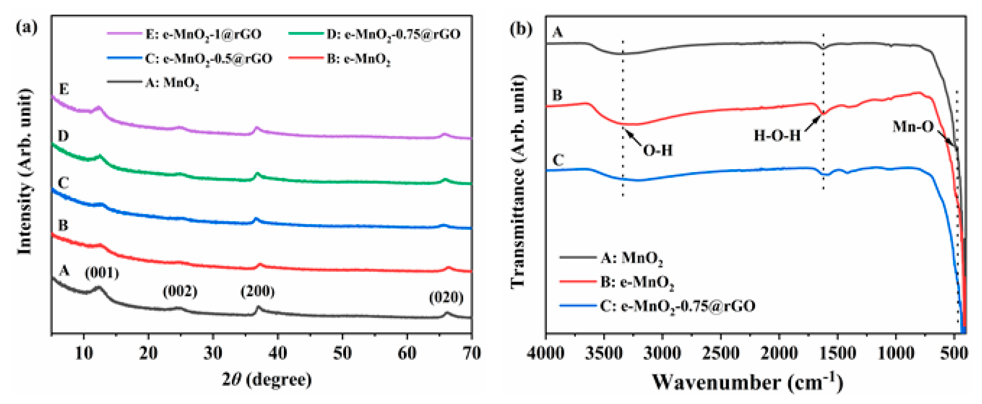
XRD patterns of MnO2, e-MnO2, e-MnO2-0.5@rGO, e-MnO2-0.75@rGO and e-MnO2-1@rGO are shown in Figure 2a. For MnO2, the diffraction peaks of 2θ at 12.3°, 24.9°, 37° and 65.5° can be indexed to birnessite-type MnO2 (δ-MnO2) (PDF# 43-1456), corresponding to (001), (002), (200) and (020) crystal planes, respectively [51]. Simultaneously, rGO was prepared using the same reduction process of the composite. Moreover, XRD patterns of rGO and GO are displayed in Figure S1 (Supplementary Information). The XRD curve of GO has a strong diffraction peak at 2θ = 11.8°, corresponding to (001) crystal plane. After reduced by hydrothermal reduction with glucose, a broad diffraction peak (002) appears at 2θ = 24.5°, indicating the reduction of GO to rGO. The position of which is close to the (002) plane of δ-MnO2, so there may be an overlap of (002) peaks for MnO2 and rGO [52]. Moreover, the existence of rGO in the composite will be further proved by subsequent SEM, TEM and XPS characterization. According to the Bragg equation, the basal plane spacing calculated from the (001) plane is about 0.72 nm. Compared with MnO2, there is no obvious change for the position of the diffraction peaks of e-MnO2, indicating that the phase structure of MnO2 has no change after ultrasonic exfoliation, but the intensity of the diffraction peaks weakened, especially the peaks corresponding to (001) and (002) planes. For the e-MnO2@rGO composites with different concentrations of PDDA (0.5, 0.75 and 1 g/L), they all present the diffraction peaks of δ-MnO2 only, which is probably because MnO2 laminas covered on the surface of rGO [53]. Moreover, with the change of the concentration, the XRD patterns of e-MnO2-0.5@rGO, e-MnO2-0.75@rGO and e-MnO2-1@rGO have little change, suggesting no effect on the phase structure of the composites for the charge regulation on the surface of e-MnO2. FTIR spectra were used to further represent the structure of MnO2, e-MnO2 and e-MnO2-0.75@rGO, as shown in Figure 2b. The position of the characteristic bands of MnO2, e-MnO2 and e-MnO2-0.75@rGO is basically similar. The band at 3345 cm−1 corresponds to the stretching vibration of the O-H bond of interlayer H2O, and the band at 1632 cm−1 is assigned to the stretching vibration of the H-O-H bond of bound water. The band at 482 cm−1 is attributed to the stretching vibration of the Mn-O bond [54]. The intensity of the band of e-MnO2 is a little stronger than MnO2, mainly because more functional groups are exposed on the surface of the nanosheets.
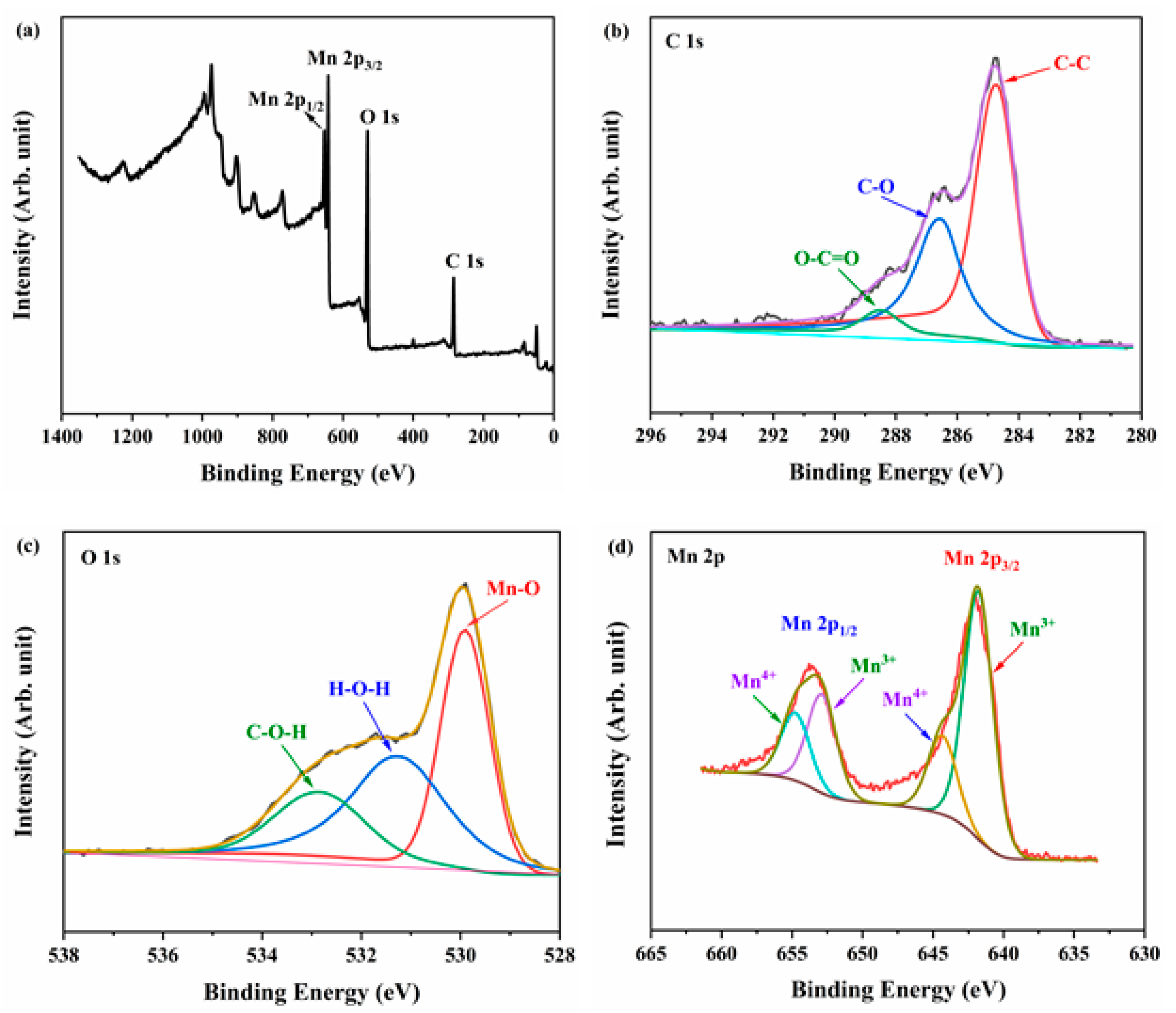
The chemical composition and oxidation state of e-MnO2-0.75@rGO were conducted by XPS, as shown in Figure 3. The existence of C, O and Mn elements is proved in the e-MnO2-0.75@rGO composite (Figure 3a). Figure 3b shows C 1s core-level XPS spectrum, where the peaks located at 284.8, 286.8 and 288.6 eV are assigned to C-C, C-O and O-C=O bonds, respectively [55,56]. The spectrum of O 1s region (Figure 3c) could be deconvolved into three peaks centered at 533.2, 531.7 and 529.4 eV, corresponding to C-O-H, H-O-H and Mn-O bonds, respectively [57,58]. Wherein H-O-H and C-O-H bonds are attributed to the adsorbed water molecules and surface functional groups of rGO in the composite, respectively, and the Mn-O bond belongs to MnO2. For Mn 2p core-level, it could be fitted into four peaks at 654.8 eV, 652.9 eV, 644.4 eV and 641.8 eV (Figure 3d), which are assigned to Mn4+(2p1/2), Mn3+(2p1/2), Mn4+(2p3/2) and Mn3+(2p1/2), respectively [59,60]. The existence of Mn3+ is probably to maintain charge neutrality and oxygen vacancies in the MnO2 lattice [60]. The XPS results further confirm that it has been synthesized successfully of the e-MnO2-0.75@rGO composite.
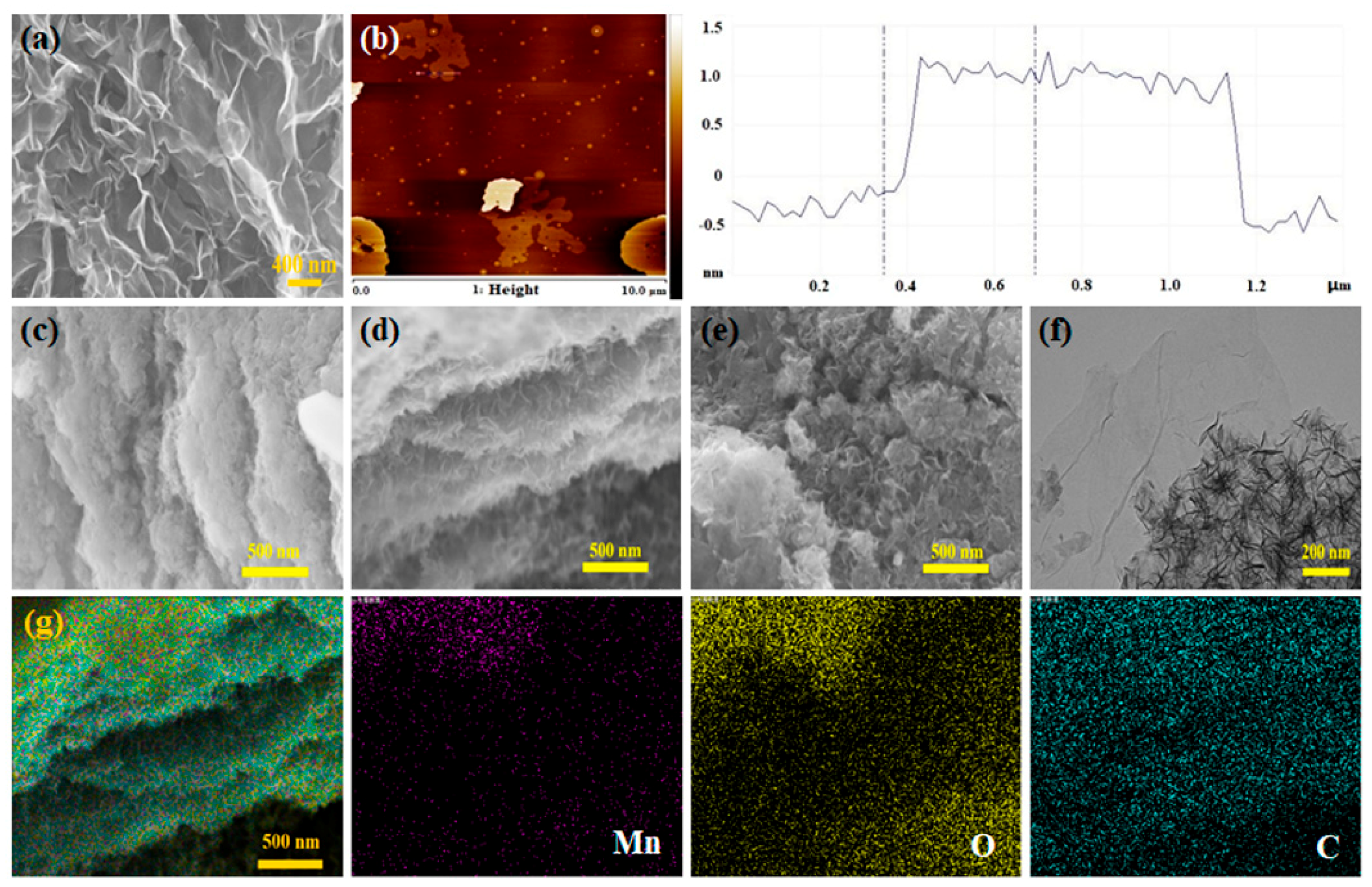
The SEM image of the as-prepared MnO2 is shown in Figure 4a. It exhibits a large area and continuous lamellar morphology with the size of several hundred nanometers, and the nanosheets cross with each other. AFM was used to represent the morphology of e-MnO2. As shown in Figure 4b, smooth nanosheets are observed, which have a large surface with a dimension of ~800 nm from the AFM image (Figure 4b, on the left), and a thickness of ~1.2 nm from the height profile (Figure 4b, on the right). The theoretical thickness of the single-layer MnO2 nanosheet is 0.52 nm [42], but it should be considered the existence of hydration on both sides of the single-layer nanosheet [61]. So the thickness of the obtained e-MnO2 nanosheet is approximately two layers. The morphologies of e-MnO2@rGO composites under different concentrations of PDDA were characterized by SEM. When the concentration of PDDA is 0.5 g/L, the nanosheets of e-MnO2-0.5@rGO are stacked, and the structure is relatively compact (Figure 4c), indicating that the dispersed lamellas failed to attract effectively and aggregated again. Although rGO could increase the conductivity of the composite, the compact structure makes it difficult for the electrolyte to enter the material. When the concentration of PDDA is 0.75 g/L, it can be observed from Figure 4d that e-MnO2-0.75@rGO composite displays a layer-by-layer structure with relatively uniform compounding, demonstrating that rGO and e-MnO2 were assembled well. As can be seen from the TEM image of e-MnO2-0.75@rGO (Figure 4f), e-MnO2 lamellas are distributed on the surface of rGO nanosheets. These e-MnO2 lamellas interlace with each other, and the material shows a relatively transparent state, indicating a less-layer structure. For the novel layer-by-layer heterostructure, it has many advantages: Firstly, the compact combination of e-MnO2 and rGO not only improves the conductivity of the composite but also mitigates the powder dropping caused by the expansion of MnO2 during the charge-discharge process. Furthermore, the cross-linking between e-MnO2 nanosheets results in a large number of pores, which make ions in electrolytes easily accessible to the layers of the nanosheets, thus greatly increasing active sites. When the concentration of PDDA increased to 1 g/L, e-MnO2-1@rGO presented a lamellar accumulation structure (Figure 4e), indicating that e-MnO2 and rGO have not formed a good assembly. As shown in Figure 4g of SEM mapping images, Mn, O and C elements distribute homogeneously over the e-MnO2-0.75@rGO architecture, which further proves the existence and interlacing distribution of MnO2 and rGO in the composite.
The specific surface area and pore structure of the e-MnO2-0.75@rGO composite were investigated by analyzing N2 adsorption-desorption isotherms and the pore size distribution curve, as shown in Figure 5. It shows a type IV isotherm with a hysteresis loop at the relative pressure of ~0.6-1.0, indicating the existence of mesoporous structure in e-MnO2-0.75@rGO (Figure 5a) [62]. The specific surface area of e-MnO2-0.75@rGO is 154.3 m2/g, which is higher or comparable compared with that reported in the literature, such as MnO2 nanowires/rGO (139.9 m2/g) [62], reduced graphene/MnO2 (120.2 m2/g) [63] and high-reduced graphene (HRGO)/MnO2 (159.1 m2/g) [63]. For a comparison, adsorption-desorption isotherms of MnO2 and rGO are displayed in Figure S2a,c (Supplementary Information). The specific surface area of MnO2 and rGO is 78.7 and 207.8 m2/g, respectively. It can be seen that the higher specific surface area of rGO plays a positive role in the composite, and the specific surface area of e-MnO2-0.75@rGO composite is significantly improved compared with that of pristine MnO2. Additionally, the pore size distribution curve reveals that the average pore size calculated by Barrett-Joyner-Halenda (BJH) model is concentrated from 20 to 40 nm (Figure 5b), demonstrating the mesoporous structure of the as-prepared composite. While the pore size distribution of MnO2 and rGO is both concentrated at ~3-4 nm (Supplementary Information, Figure S2b,d), so the porosity is owing to the composite layer-by-layer architecture formed by MnO2 and rGO, which is ascribed to the cross-linked structure constructed by self-assembly of the folded nanosheets. High specific surface area and suitable pore size are favorable for ions transport during the charge-discharge process.

3.2. Electrochemical Performance

For the evaluation of electrochemical performance, CV curves at various scan rates and GCD curves at various current densities were tested, as shown in Figure 6. Figure 6a–c show CV curves of e-MnO2-0.5@rGO, e-MnO2-0.75@rGO and e-MnO2-1@rGO, respectively. CV curves of e-MnO2@rGO obtained at different PDDA concentrations are similar in shape and approximate in rectangle, indicating that the materials present good pseudocapacitance characteristics. At the same scan rate, the CV curve of e-MnO2-0.75@rGO has the maximum current response, demonstrating the maximum specific capacitance. Moreover, GCD curves of e-MnO2-0.5@rGO, e-MnO2-0.75@rGO and e-MnO2-1@rGO are shown in Figure 6d–f), respectively. These GCD curves at different current densities are close to symmetric triangles, indicating good reversibility. At the same current density, the GCD curve of e-MnO2-0.75@rGO has the longest discharge time, also manifesting the highest specific capacitance, which is consistent with the CV results. At a current density of 1 A/g, the specific capacitance of e-MnO2-0.5@rGO, e-MnO2-0.75@rGO and e-MnO2-1@rGO calculated by the GCD curves is 236 F/g, 456 F/g and 298 F/g, respectively. Combined with the above Zeta potential results after surface charge regulation, the higher the absolute value of Zeta potential is, the more stable the system is, so the self-assembly effect is better. When the concentration of PDDA was 0.5 g/L, due to the low concentration of the charge regulating solution, the self-assembly via electrostatic gravity was not ideal, and the nanosheets were aggregated and stacked, which reduced the number of the active sites of MnO2 and affected its specific capacitance. However, Zeta potential at 1 g/L of PDDA decreased compared with that at 0.75 g/L of PDDA, which did not achieve complete assembly. Furthermore, the higher concentration of PDDA made the long molecular chain at the outer end cause micelle expansion and sedimentation. While excess PDDA polymers mixed in the composite slowed down the agglomeration, it was bound to reduce the electrical conductivity of the material, thus affecting the electrochemical performance, resulting in the decline of the specific capacitance. The results correspond with SEM analysis.
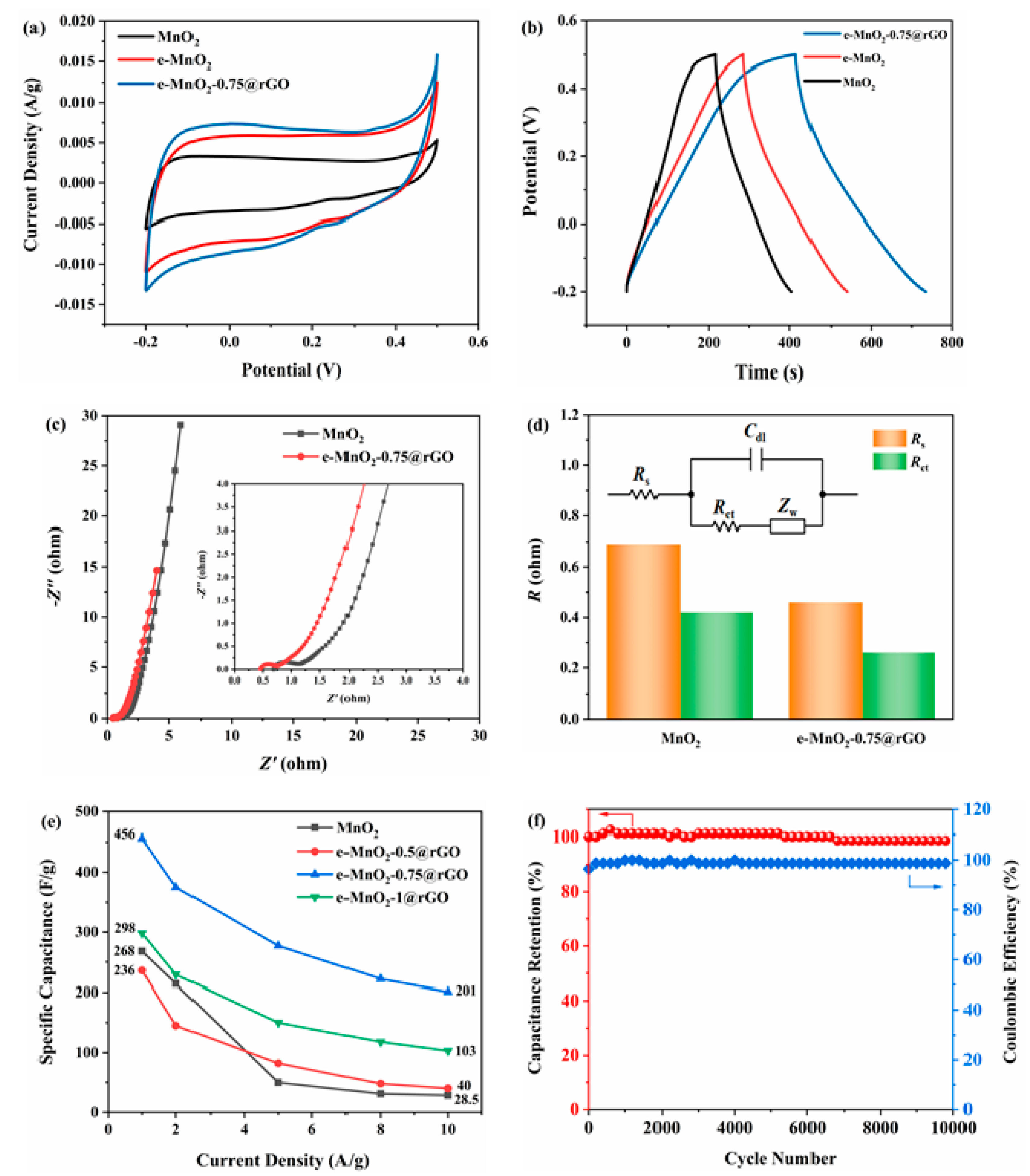
For a comparison, CV curves at 5 mV/s and GCD curves at 1 A/g of MnO2, e-MnO2 and e-MnO2-0.75@rGO are displayed in Figure 7a,b). The CV curve area of e-MnO2 is larger than that of pristine MnO2. The composite of e-MnO2-0.75@rGO shows the largest closed area, indicating the highest specific capacitance among the three. The specific capacitance of MnO2, e-MnO2 and e-MnO2-0.75@rGO is 268, 360 and 456 F/g, respectively, at a current density of 1 A/g, calculated from the charge-discharge curve in Figure 7b. (The average values and standard deviations were given in Figure S3 of supplementary information.) Compared with pristine MnO2, e-MnO2 has a larger specific surface, and more active sites are exposed to the electrolyte, so it has higher specific capacitance than pristine MnO2. Furthermore, e-MnO2-0.75@rGO composite has the highest specific capacitance, 70% higher than that of pristine MnO2, mainly because rGO and e-MnO2 were laminated in a layer-by-layer structure, which improves the conductivity of the material and inhibits the stacking of the nanosheets. According to Figure 7c, for the Nyquist plots of EIS, the intercept at the real axis represents the equivalent series resistance (Rs), including electrolyte resistance, contact resistance between the electrode material and the current collector, or the internal resistance of the material [64]. The diameter of the semi-arc intersecting at the real axis represents the charge transfer resistance (Rct), the value of which is proportional to the Rct. As can be seen in Figure 7c, the diameter of the semi-arc for e-MnO2-0.75@rGO is very small, indicating lower Rct. The plots were fitted according to the equivalent circuit given in Figure 7d, and the fitting results are also shown in Figure 7d. The Rs of MnO2 and e-MnO2-0.75@rGO is 0.69 Ω and 0.46 Ω, respectively. Moreover, the corresponding Rct is 0.42 Ω and 0.26 Ω, manifesting that the Rs and Rct of e-MnO2-0.75@rGO are both lower than pristine MnO2. It is further demonstrated that e-MnO2-0.75@rGO composite with lamellar structure has good conductivity, and the lamellar structure could contribute to the transfer of electrolyte ions, while rGO is also conducive to reducing the internal resistance of the material. Figure 7e shows the rate performance of MnO2, e-MnO2-0.5@rGO, e-MnO2-0.75@rGO and e-MnO2-1@rGO at the current densities increasing from 1 to 10 A/g. Obviously, the capacitance retention of e-MnO2-0.5@rGO, e-MnO2-0.75@rGO and e-MnO2-1@rGO are 16.9%, 44% and 34.6%, respectively, which is more superior than that of pristine MnO2 (10.6%), owing to the role of rGO in stabilizing the architecture. In particular, the rate performance of e-MnO2-0.75@rGO is significantly the best in the e-MnO2@rGO composites with different concentrations of PDDA, and it has the highest specific capacitance at different current densities of 1, 2, 5, 8 and 10 A/g. Figure 7f shows the cycle performance and coulombic efficiency of the e-MnO2-0.75@rGO composite. It can be seen that the specific capacitance retention remains at 98.7% of the initial value after 10,000 charge-discharge cycles at a current density of 20 A/g, and coulombic efficiency is about 98.7%.
The specific capacitance of e-MnO2-0.75@rGO composite synthesized by electrostatic self-assembly combined with hydrothermal reduction after exfoliating MnO2 nanosheets in this work was compared with the composites of MnO2 with graphene prepared via a variety of methods reported in the literature [47,63,64,65,66,67,68,69]. As shown in Table 1, in terms of the specific capacitance, the result of our work is comparable.
Compared with pristine MnO2, the improved electrochemical performance of e-MnO2-0.75@rGO composite is mainly due to the following reasons. Briefly, a layer-by-layer heterostructure of e-MnO2-0.75@rGO facilitates the diffusion of electrolyte ions. Meanwhile, the architecture was developed by the self-assembly of graphene nanosheets and e-MnO2 nanoflakes, which could effectively inhibit the restacking of e-MnO2 and graphene. In addition, the intersecting e-MnO2 nanosheets formed a large number of pores, promoting rapid faradaic reactions. Furthermore, the synergistic effect of components must be mentioned. As a conductive layer in the heterostructure, rGO improves the electrical conductivity of the e-MnO2-0.75@rGO composite, which is beneficial to the improvement of the overall electrochemical performance [70,71].
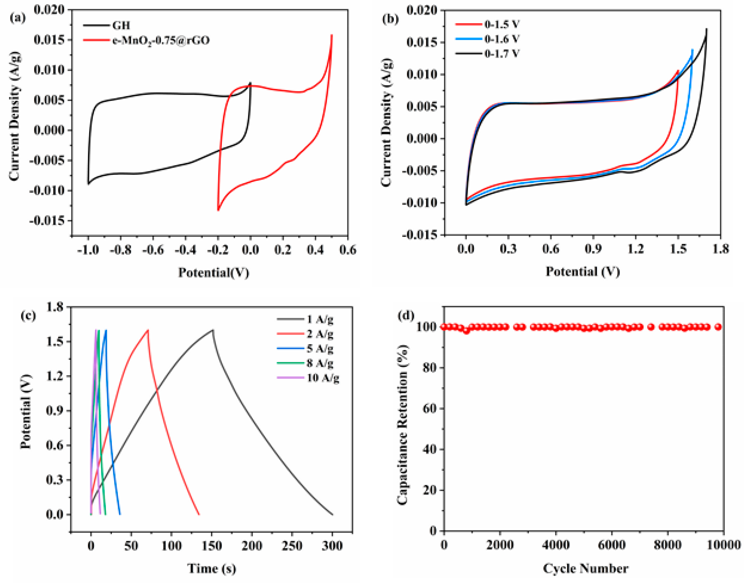
Additionally, an asymmetric supercapacitor (ASC) device was assembled, and its electrochemical performance was evaluated. The as-prepared e-MnO2-0.75@rGO was used as the positive electrode, graphene hydrogel (GH) was used as the negative electrode and 6 M KOH was used as the electrolyte. Figure 8a shows CV curves of the GH negative electrode and e-MnO2-0.75@rGO positive electrode at the scan rate of 5 mV/s. The potential window of the negative electrode is approximately −1–0 V, and that of the positive electrode is approximately −0.2–0.5 V. Figure 8b displays CV curves under various potential windows. It can be observed that CV curves remain a good rectangle when the voltage windows are ~0–1.5 V and ~0–1.6 V; while the voltage rises to 1.7 V, slight polarization occurs. Therefore, ~0–1.6 V was selected as the potential window of the ASC device. GCD curves of e-MnO2-0.75@rGO//GH ASC at current densities of 1, 2, 5, 8 and 10 A/g with the potential window of ~0–1.6 V are shown in Figure 8c. All the GCD curves display approximately symmetrical triangles, indicating good reversibility of the device. The calculated specific capacitance could reach 94 F/g at 1 A/g and still keep 35 F/g at 10 A/g. The cycle performance of the device is revealed in Figure 8d. The specific capacitance retention of e-MnO2-0.75@rGO//GH ASC can reach 99.3% after 10,000 cycles at 20 A/g, demonstrating good stability.

4. Conclusions

In summary, MnO2 nanoflakes with a thickness of ~1.2 nm and size of ~800 nm were obtained by ultrasonic exfoliation and charge regulated by the appropriate concentration of PDDA (0.75 g/L). Then MnO2 and GO nanosheets were self-assembled by electrostatic force. The composite of e-MnO2-0.75@rGO with layer-by-layer heterostructure was acquired after hydrothermal reduction by glucose. The composite exhibits excellent electrochemical performance. In 6 M KOH electrolyte, the specific capacitance of e-MnO2-0.75@rGO is 456 F/g at a current density of 1 A/g, which is much higher than that of pristine MnO2 (268 F/g). Even at 10 A/g, the specific capacitance still retains 201 F/g, and the specific capacitance retention is 98.7% after 10,000 charge-discharge cycles at 20 A/g. It shows that rGO improves the conductivity of the material, and the layer structure formed by rGO is conducive to the migration of ions in the electrolyte, so the specific capacitance of the composite is greatly enhanced. The improved electrochemical performance is attributed to the synergistic effect of architecture coupled with components, including the rate of ion transport and faradaic reaction, plenty of active sites, less restacking as well as improved electrical conductivity. Moreover, the assembled e-MnO2-0.75@rGO//GH ASC device shows a specific capacitance of 94 F/g at 1 A/g with a potential window of ~0–1.6 V and better cycle stability with capacitance retention of 99.3% over 10,000 cycles at 20 A/g. We believe that this work may provide a reference for the synthesis of the composites with layer-by-layer structure by self-assembly method and the basis for the design and comparison of electrode materials for high-performance supercapacitors. Reasonable design and construction of heterostructure have positive effects on the electrochemical performance. In future studies, we need to further optimize the structure and improve the electrochemical performance, as well as carry out researches on the interface mechanism of the heterostructure so as to better exploit the potential of MnO2/rGO composites in the application of supercapacitors.

Supplementary Materials

The following supporting information can be downloaded at: https://www.mdpi.com/article/10.3390/membranes12111044/s1, preparation of GH anode materials, preparation of samples for FTIR, Table S1: Zeta potential of e-MnO2 regulated by different concentrations of PDDA, Figure S1: XRD patterns of GO and rGO, Figure S2. Adsorption-desorption isotherms of (a) MnO2 and (c) rGO and the pore-size distribution of (b) MnO2 and (d) rGO and Figure S3: The average specific capaitance of MnO2, e-MnO2-0.5@rGO, e-MnO2-0.75@rGO and e-MnO2-1@rGO (1 A/g).

Author Contributions

Methodology, L.C. (Lei Chen); validation, G.T., M.J., and S.Z.; investigation, L.C. (Lei Chen); resources, L.C. (Ling Chen); data curation, L.C. (Lei Chen); writing—original draft preparation, T.L.; writing—review and editing, T.L.; supervision, L.C. (Ling Chen); project administration, T.L. and L.C. (Ling Chen); funding acquisition, T.L. All authors have read and agreed to the published version of the manuscript.

Funding

This research was funded by the National Natural Science Foundation of China (51904077) and the Youth Science Fund of Northeast Petroleum University (2019QNQ-03).

Institutional Review Board Statement

Not applicable for studies not involving humans or animals.

Data Availability Statement

Not applicable.

Conflicts of Interest

The authors declare no conflict of interest.

References

  1. Miller, J.R.; Simon, P. Materials science: Electrochemical capacitors for energy management. Science 2008, 321, 651–652. [Google Scholar] [CrossRef] [PubMed] [Green Version]
  2. Yu, L.; Chen, G.Z. Redox electrode materials for supercapatteries. J. Power Sources 2016, 326, 604–612. [Google Scholar] [CrossRef]
  3. Wei, L.; Sevilla, M.; Fuertes, A.B.; Mokaya, R.; Yushin, G. Hydrothermal carbonization of abundant renewable natural organic chemicals for high-performance supercapacitor electrodes. Adv. Energy Mater. 2011, 1, 356–361. [Google Scholar] [CrossRef] [Green Version]
  4. Bai, X.; Hu, X.; Zhou, S.; Yan, J.; Sun, C.; Chen, P.; Li, L. In situ polymerization and characterization of grafted poly (3,4-ethylenedioxythiophene)/multiwalled carbon nanotubes composite with high electrochemical performances. Electrochim. Acta 2013, 87, 394–400. [Google Scholar] [CrossRef]
  5. Chen, T.; Dai, L. Carbon nanomaterials for high-performance supercapacitors. Mater. Today 2013, 16, 272–280. [Google Scholar] [CrossRef]
  6. Wang, G.; Liang, R.; Liu, L.; Zhong, B. Improving the specific capacitance of carbon nanotubes-based supercapacitors by combining introducing functional groups on carbon nanotubes with using redox-active electrolyte. Electrochim. Acta 2014, 115, 183–188. [Google Scholar] [CrossRef]
  7. Xu, Y.; Lin, Z.; Zhong, X.; Huang, X.; Weiss, N.O.; Huang, Y.; Duan, X. Holey graphene frameworks for highly efficient capacitive energy storage. Nat. Commun. 2014, 5, 4554. [Google Scholar] [CrossRef] [Green Version]
  8. Yang, W.; Ni, M.; Ren, X.; Tian, Y.; Li, N.; Su, Y.; Zhang, X. Graphene in supercapacitor applications. Curr. Opin. Colloid Interface Sci. 2015, 20, 416–428. [Google Scholar] [CrossRef]
  9. Zhang, Y.; Li, L.; Su, H.; Huang, W.; Dong, X. Binary metal oxide: Advanced energy storage materials in supercapacitors. J. Mater. Chem. A 2015, 3, 43–59. [Google Scholar] [CrossRef]
  10. An, C.; Zhang, Y.; Guo, H.; Wang, Y. Metal oxide-based supercapacitors: Progress and prospective. Nanoscale Adv. 2019, 1, 4644–4658. [Google Scholar] [CrossRef] [PubMed]
  11. Guo, W.; Guo, X.; Yang, L.; Wang, T.; Zhang, M.; Duan, G.; Liu, X.; Li, Y. Synthetic melanin facilitates MnO supercapacitors with high specific capacitance and wide operation potential window. Polymer 2021, 235, 124276. [Google Scholar] [CrossRef]
  12. Gao, S.; Sun, Y.; Lei, F.; Liang, L.; Liu, J.; Bi, W.; Pan, B.; Xie, Y. Ultrahigh energy density realized by a single-layer β-Co(OH)2 all-solid-state asymmetric supercapacitor. Angew. Chem. Int. Ed. 2014, 53, 12789–12793. [Google Scholar] [CrossRef]
  13. Nguyen, T.; Montemor, M. Metal oxide and hydroxide-based aqueous supercapacitors: From charge storage mechanisms and functional electrode engineering to need-tailored devices. Adv. Sci. 2019, 6, 1801797. [Google Scholar] [CrossRef]
  14. Snook, G.A.; Kao, P.; Best, A.S. Conducting-polymer-based supercapacitor devices and electrodes. J. Power Sources 2011, 196, 1–12. [Google Scholar] [CrossRef]
  15. Liu, T.; Finn, L.; Yu, M.; Wang, H.; Zhai, T.; Lu, X.; Tong, Y.; Li, Y. Polyaniline and polypyrrole pseudocapacitor electrodes with excellent cycling stability. Nano Lett. 2014, 14, 2522–2527. [Google Scholar] [CrossRef] [PubMed]
  16. Zhu, T.; Wang, Z.; Ding, S.; Chen, J.S.; Lou, X.W. Hierarchical nickel sulfide hollow spheres for high performance supercapacitors. RSC Adv. 2011, 1, 397–400. [Google Scholar] [CrossRef]
  17. Sugimoto, W.; Iwata, H.; Yokoshima, K.; Murakami, Y.; Takasu, Y. Proton and electron conductivity in hydrous ruthenium oxides evaluated by electrochemical impedance spectroscopy: The origin of large capacitance. J. Phys. Chem. B 2005, 109, 7330–7338. [Google Scholar] [CrossRef]
  18. Wang, J.; Dong, S.; Ding, B.; Wang, Y.; Hao, X.; Dou, H.; Xia, Y.; Zhang, X. Pseudocapacitive materials for electrochemical capacitors: From rational synthesis to capacitance optimization. Natl. Sci. Rev. 2017, 4, 71–90. [Google Scholar] [CrossRef] [Green Version]
  19. Jian, T.; Zhu, J.; Ma, W.; Yan, X.; Li, G.; Zhou, J. Interconnected two-dimensional MnO2 nanosheets anchored on threedimensional porous Cu skeleton as a high-performance cathode for energy storage. Appl. Surf. Sci. 2020, 529, 147152. [Google Scholar] [CrossRef]
  20. Swain, N.; Mitra, A.; Saravanakumar, B.; Balasingam, S.K.; Mohanty, S.; Nayak, S.K.; Ramadoss, A. Construction of three-dimensional MnO2/Ni network as an efficient electrode material for high performance supercapacitors. Electrochim. Acta 2020, 342, 136041. [Google Scholar] [CrossRef]
  21. Toupin, M.; Brousse, T.; B’elanger, D. Charge storage mechanism of MnO2 electrode used in aqueous electrochemical capacitor. Chem. Mater. 2004, 16, 3184–3190. [Google Scholar] [CrossRef]
  22. Lang, X.; Hirata, A.; Fujita, T.; Chen, M. Nanoporous metal/oxide hybrid electrodes for electrochemical supercapacitors. Nat. Nanotechol. 2011, 6, 232–236. [Google Scholar] [CrossRef] [PubMed]
  23. Yao, J.; Pan, Q.; Yao, S.; Duan, L.; Liu, J. Mesoporous MnO2 nanosphere/graphene sheets as electrodes for supercapacitor synthesized by a simple and inexpensive reflux reaction. Electrochem. Acta 2017, 238, 30–35. [Google Scholar] [CrossRef]
  24. Jadhav, S.; Kalubarme, R.S.; Terashima, C.; Kale, B.B.; Godbole, V.; Fujishima, A.; Gosavi, S.W. Manganese dioxide/reduced graphene oxide composite an electrode material for high-performance solid state supercapacitor. Electrochim. Acta 2019, 299, 34–44. [Google Scholar] [CrossRef]
  25. Liu, A.; Zhang, H.; Wang, G.; Zhang, J.; Zhang, S. Sandwich-like NiO/rGO nanoarchitectures for 4 V solid-state asymmetric-supercapacitors with high energy density. Electrochim. Acta 2018, 283, 1401–1410. [Google Scholar] [CrossRef]
  26. Kumar, A.; Sarkar, D.; Mukherjee, S.; Patil, S.; Sarma, D.D.; Shukla, A. Realizing an asymmetric supercapacitor employing carbon nanotubes anchored to Mn3O4 cathode and Fe3O4 anode. ACS Appl. Mater. Interfaces 2018, 10, 42484–42493. [Google Scholar] [CrossRef] [Green Version]
  27. Shi, Z.; Xing, L.; Liu, Y.; Gao, Y.; Liu, J. A porous biomass-based sandwich-structured Co3O4@carbon fiber@Co3O4 composite for high-performance supercapacitors. Carbon 2018, 129, 819–825. [Google Scholar] [CrossRef]
  28. Chen, L.; Wang, F.; Tian, Z.; Guo, H.; Cai, C.; Wu, Q.; Du, H.; Liu, K.; Hao, Z.; He, S.; et al. Wood-derived high-mass-loading MnO2 composite carbon electrode enabling high energy density and high-rate supercapacitor. Small 2022, 18, 2201307. [Google Scholar] [CrossRef]
  29. Xu, C.; Li, Z.; Yang, C.; Zou, P.; Xie, B.; Lin, Z.; Zhang, Z.; Li, B.; Kang, F.; Wong, C.P. An ultralong, highly oriented nickel-nanowire-array electrode scaffold for high-performance compressible pseudocapacitors. Adv. Mater. 2016, 28, 4105–4110. [Google Scholar] [CrossRef]
  30. Guo, W.; Yu, C.; Li, S.; Wang, Z.; Yu, J.; Huang, H.; Qiu, J. Strategies and insights towards the intrinsic capacitive properties of MnO2 for supercapacitors: Challenges and perspectives. Nano Energy 2019, 57, 459–472. [Google Scholar] [CrossRef]
  31. Jana, M.; Saha, S.; Samanta, P.; Murmu, N.C.; Kim, N.H.; Kuila, T.; Lee, J.H. Growth of Ni-Co binary hydroxide on reduced graphene oxide surface by a successive ionic layer adsorption and reaction (SILAR) method for high performance asymmetric supercapacitor electrode. J. Mater. Chem. A 2016, 4, 2188–2197. [Google Scholar] [CrossRef]
  32. Govindasamy, M.; Shanthi, S.; Elaiyappillai, E.; Wang, S.F.; Johnson, P.M.; Ikeda, H.; Hayakawa, Y.; Ponnusamy, S.; Muthamizhchelvan, C. Fabrication of hierarchical NiCo2S4@CoS2 nanostructures on highly conductive flexible carbon cloth substrate as a hybrid electrode material for supercapacitors with enhanced electrochemical performance. Electrochim. Acta 2019, 293, 328–337. [Google Scholar] [CrossRef]
  33. Chinnapaiyan, S.; Das, H.T.; Chen, S.M.; Govindasamy, M.; Alshgari, R.A.; Fan, C.H.; Huang, C.H. CoAl2O4 nanoparticles modified carbon nanofibers as high-efficiency bifunctional electrocatalyst: An efficient electrochemical aqueous asymmetric supercapacitors and non-enzymatic electrochemical sensors. J. Alloy. Compd. 2023, 931, 167553. [Google Scholar] [CrossRef]
  34. Yang, W.; Gao, Z.; Wang, J.; Ma, J.; Zhang, M.; Liu, L. Solvothermal one-step synthesis of Ni-Al layered double hydroxide/carbon nanotube/reduced graphene oxide sheet ternary nanocomposite with ultrahigh capacitance for supercapacitors. ACS Appl. Mater. Interfaces 2013, 5, 5443–5454. [Google Scholar] [CrossRef] [PubMed]
  35. Ma, Z.; Shao, G.; Fan, Y.; Wang, G.; Song, J.; Shen, D. Construction of hierarchical α-MnO2 nanowires@ultrathin δ-MnO2 nanosheets core-shell nanostructure with excellent cycling stability for high-power asymmetric supercapacitor electrodes. ACS Appl. Mater. Interfaces 2016, 8, 9050–9058. [Google Scholar] [CrossRef]
  36. Allen, M.J.; Tung, V.C.; Kaner, R.B. Honeycomb carbon: A review of graphene. Chem. Rev. 2010, 110, 132–145. [Google Scholar] [CrossRef]
  37. Zong, Q.; Zhang, Q.; Mei, X.; Li, Q.; Zhou, Z.; Li, D.; Chen, M.; Shi, F.; Sun, J.; Yao, Y.; et al. Facile synthesis of Na-doped MnO2 nanosheets on carbon nanotube fibers for ultrahigh-energy-density all-solid-state wearable asymmetric supercapacitors. ACS Appl. Mater. Interfaces 2018, 10, 37233–37241. [Google Scholar] [CrossRef]
  38. Chen, X.P.; Wen, J.; Zhao, C.X.; Li, Y.T.; Wang, N. Synthesis of core-shell structured MnO2 petal nanosheet@carbon sphere composites and their application as supercapacitor electrodes. Chem. Sel. 2018, 3, 9301–9307. [Google Scholar] [CrossRef]
  39. Ren, K.; Liu, Z.; Wei, T.; Fan, Z. Recent developments of transition metal compounds-carbon hybrid electrodesfor high energy/power supercapacitor. Nano-Micro Lett. 2021, 13, 129. [Google Scholar] [CrossRef]
  40. Kumar, S.; Saeed, G.; Zhu, L.; Hui, K.N.; Kim, N.H.; Lee, J.H. 0D to 3D carbon-based networks combined with pseudocapacitive electrode material for high energy density supercapacitor: A review. Chem. Eng. J. 2021, 403, 126352. [Google Scholar] [CrossRef]
  41. Jana, M.; Saha, S.; Samanta, P.; Murmu, N.C.; Kim, N.H.; Kuila, T.; Lee, J.H. A successive ionic layer adsorption and reaction (SILAR) method to fabricate a layer-by-layer (LbL) MnO2-reduced graphene oxide assembly for supercapacitor application. J. Power Sources 2017, 340, 380–392. [Google Scholar] [CrossRef]
  42. Oliveira, D.A.; Lutkenhaus, J.L.; Siqueira, J.R., Jr. Building up nanostructured layer-by-layer films combining reduced graphene oxide-manganese dioxide nanocomposite in supercapacitor electrodes. Thin Solid Film. 2021, 718, 138483. [Google Scholar] [CrossRef]
  43. Ding, Y.; Zhang, N.; Zhang, J.; Wang, X.; Jin, J.; Zheng, X.; Fang, Y. The additive-free electrode based on the layered MnO2 nanoflowers/reduced, graphene oxide film for high performance supercapacitor. Ceram. Int. 2017, 43, 5374–5381. [Google Scholar] [CrossRef]
  44. Amir, F.Z.; Pham, V.H.; Schultheis, E.M.; Dickerson, J.H. Flexible, all-solid-state, high-cell potential supercapacitors based on holey reduced graphene oxide/manganese dioxide nanosheets. Electrochim. Acta 2018, 260, 944–951. [Google Scholar] [CrossRef]
  45. Yuan, T.; Cui, X.; Liu, X.; Qu, X.; Sun, J. Highly tough, stretchable, self-healing, and recyclable hydrogels reinforced by in situ-formed polyelectrolyte complex nanoparticles. Macromolecules 2019, 52, 3141–3149. [Google Scholar] [CrossRef]
  46. Liu, Z.; Xu, K.; Sun, H.; Yin, S. One-step synthesis of single-layer MnO2 nanosheets with multi-role sodium dodecyl sulfate for high-performance pseudocapacitors. Small 2015, 11, 2182–2191. [Google Scholar] [CrossRef] [PubMed]
  47. Zheng, M. PE-Based Lithium Ion Battery Separator Was Prepared Based on Layer-by-layer Self-Assembly Technology. Master’s Thesis, Tianjin University of Science & Technology, Tianjin, China, 2019. [Google Scholar]
  48. Kovtyukhova, N.I.; Ollivier, P.J.; Martin, B.R.; Mallouk, T.E.; Chizhik, S.A.; Buzaneva, E.V.; Gorchinskiy, A.D. Layer-by-layer assembly of ultrathin composite films from micron-sized graphite oxide sheets and polycations. Chem. Mater. 1999, 11, 771–778. [Google Scholar] [CrossRef]
  49. Hao, Q. Preparation and supercapacitive performances of layer by layer assembled graphene/polyaniline composite electrode. Master’s Thesis, Xi’an University of Science and Technology, Xi’an, China, 2017. [Google Scholar]
  50. Huang, M.; Wang, Y.; Chen, J.; He, D.; He, J.; Wang, Y. Biomimetic design of Ni Co LDH composites linked by carbon nanotubes with plant conduction tissues characteristic for hybrid supercapacitors. Electrochim. Acta 2021, 381, 138289. [Google Scholar] [CrossRef]
  51. Zhang, X.; Miao, W.; Li, C.; Sun, X.; Wang, K.; Ma, Y. Microwave-assisted rapid synthesis of birnessite-type MnO2 nanoparticles for high performance supercapacitor applications. Mater. Res. Bull. 2015, 71, 111–115. [Google Scholar] [CrossRef]
  52. Chen, Q.; Meng, Y.; Hu, C.; Zhao, Y.; Shao, H.; Chen, N.; Qu, L. MnO2-modified hierarchical graphene fiber electrochemical supercapacitor. J. Power Sources 2014, 247, 32–39. [Google Scholar] [CrossRef]
  53. Yan, J.; Fan, Z.; Wei, T.; Qian, W.; Zhang, M.; Wei, F. Fast and reversible surface redox reaction of graphene-MnO2 composites as supercapacitor electrodes. Carbon 2010, 48, 3825–3833. [Google Scholar] [CrossRef]
  54. Yang, X.; Makita, Y.; Liu, Z.H.; Sakane, K.; Ooi, K. Structural characterization of self-assembled MnO2 nanosheets from birnessite manganese oxide single crystals. Chem. Mater. 2004, 16, 5581–5588. [Google Scholar] [CrossRef]
  55. Huang, S.Y.; Le, P.A.; Yen, P.J.; Lu, Y.C.; Sahoo, S.K.; Cheng, H.W.; Chiu, P.W.; Tseng, T.Y.; Wei, K.H. Cathodic plasma-induced syntheses of graphene nanosheet/MnO2/WO3 architectures and their use in supercapacitors. Electrochim. Acta 2020, 342, 136043. [Google Scholar] [CrossRef]
  56. Niu, Z.; Yue, T.; Hu, W.; Sun, W.; Hu, Y.; Xu, Z. Covalent bonding of MnO2 onto graphene aerogel forwards: Efficiently catalytic degradation of organic wastewater. Appl. Surf. Sci. 2019, 496, 143585. [Google Scholar] [CrossRef]
  57. Liu, B.; Cao, Z.; Yang, Z.; Qi, W.; He, J.; Pan, P.; Li, H.; Zhang, P. Flexible micro-supercapacitors fabricated from MnO2 nanosheet/graphene composites with black phosphorus additive. Prog. Nat. Sci. Mater. Int. 2022, 32, 10–19. [Google Scholar] [CrossRef]
  58. Zhao, Z.; Shen, T.; Liu, Z.; Qi, W.; He, J.; Pan, P.; Li, H.; Zhang, P. Facile fabrication of binder-free reduced graphene oxide/MnO2/Ni foam hybrid electrode for high-performance supercapacitors. J. Alloy. Compd. 2019, 812, 152124. [Google Scholar] [CrossRef]
  59. Wang, M.; Chen, K.; Liu, J.; He, Q.; Li, G.; Li, F. Efficiently enhancing electrocatalytic activity of α-MnO2 nanorods/N-doped ketjenblack carbon for oxygen reduction reaction and oxygen evolution reaction using facile regulated hydrothermal treatment. Catalysts 2018, 8, 138. [Google Scholar] [CrossRef] [Green Version]
  60. Hastuti, E.; Subhan, A.; Amonpattaratkit, P.; Zainuri, M.; Suasmoro, S. The effects of Fe-doping on MnO2: Phase transitions, defect structures and its influence on electrical properties. RSC Adv. 2021, 11, 7808–7823. [Google Scholar] [CrossRef]
  61. Kai, K.; Yoshida, Y.; Kageyama, H.; Saito, G.; Ishigaki, T.; Furukawa, Y.; Kawamata, J. Room-temperature synthesis of manganese oxide monosheets. J. Am. Chem. Soc. 2008, 130, 15938–15943. [Google Scholar] [CrossRef] [PubMed]
  62. Ma, W.; Chen, S.; Yang, S.; Chen, W.; Cheng, Y.; Guo, Y.; Peng, S.; Ramakrishna, S.; Zhu, M. Hierarchical MnO2 nanowire/graphene hybrid fibers with excellent electrochemical performance for flexible solid-state supercapacitors. J. Power Sources 2016, 306, 481–488. [Google Scholar] [CrossRef]
  63. Wang, X.; Chen, L.; Zhang, S.; Chen, X.; Li, Y.; Liu, J.; Lu, F.; Tang, Y. Compounding δ-MnO2 with modified graphene nanosheets for highly stable asymmetric supercapacitors. Colloids Surf. A 2019, 573, 57–66. [Google Scholar] [CrossRef]
  64. Vedpathak, A.S.; Desai, M.A.; Bhagwat, S.; Sartale, S.D. Green strategy for the synthesis of K+ pre-inserted MnO2/rGO and its electrochemical conversion to Na-MnO2/rGO for high-performance supercapacitors. Energy Fuels 2022, 36, 4596–4608. [Google Scholar] [CrossRef]
  65. Zhang, H.; Lin, L.; Wu, B.; Hu, N. Vertical carbon skeleton introduced three-dimensional MnO2 nanostructured composite electrodes for high-performance asymmetric supercapacitors. J. Power Sources 2020, 476, 228527. [Google Scholar] [CrossRef]
  66. Shi, Y.; Zhang, M.; Zhang, L.; Cui, X.; Zhu, X.; Zhao, J.; Jin, D.; Yang, D.; Li, J. Reduced graphene oxide coated manganese dioxide electrode prepared by polyvinylpyrrolidone assisted electrodeposition. Vacuum 2022, 199, 110925. [Google Scholar] [CrossRef]
  67. Ghasemi, S.; Hosseini, S.R.; Boore-Talari, O. Sonochemical assisted synthesis MnO2/RGO nanohybrid as effective electrode material for supercapacitor. Ultrason. Sonochemistry 2017, 40, 675–685. [Google Scholar] [CrossRef]
  68. Liu, Y.; Miao, X.; Fang, J.; Zhang, X.; Chen, S.; Li, W.; Feng, W.; Chen, Y.; Wang, W.; Zhang, Y. Layered-MnO2 nanosheet grown on nitrogen-doped graphene template as a composite cathode for flexible solid-state asymmetric supercapacitor. ACS Appl. Mater. Interfaces 2016, 8, 5251–5260. [Google Scholar] [CrossRef]
  69. Zhang, Q.; Wu, X.; Zhang, Q.; Yang, F.; Dong, H.; Sui, J.; Dong, L. One-step hydrothermal synthesis of MnO2/graphene composite for electrochemical energy storage. J. Electroanal. Chem. 2019, 837, 108–115. [Google Scholar] [CrossRef]
  70. Cao, L.; Li, H.; Liu, X.; Liu, S.; Zhang, L.; Xu, W.; Yang, H.; Hou, H.; He, S.; Zhao, Y.; et al. Nitrogen, sulfur co-doped hierarchical carbon encapsulated in graphenewith ‘‘sphere-in-layer” interconnection for high-performance supercapacitor. J. Colloid Interface Sci. 2021, 599, 443–452. [Google Scholar] [CrossRef] [PubMed]
  71. Liu, S.; Yang, H.; Sui, L.; Jiang, S.; Hou, H. Self-adhesive polyimide (PI)@reduced graphene oxide (RGO)/PI@carbon nanotube (CNT) hierarchically porous electrodes: Maximizing the utilization of electroactive materials for organic Li-ion batteries. Energy Technol. 2020, 8, 2000397. [Google Scholar] [CrossRef]
Figure 1. Schematic synthesis procedure of e-MnO2@rGO composites.
Membranes 12 01044 g001
Figure 2. (a) XRD patterns of MnO2, e-MnO2, e-MnO2-0.5@rGO, e-MnO2-0.75@rGO and e-MnO2-1@rGO and (b) FTIR spectra of MnO2, e-MnO2 and e-MnO2-0.75@rGO.
Membranes 12 01044 g002
Figure 3. XPS spectra of (a) survey spectrum, (b) C 1s, (c) O 1s and (d) Mn 2p core level for e-MnO2-0.75@rGO.
Membranes 12 01044 g003
Figure 4. (a) SEM image of MnO2, (b) AFM image and the height profile of e-MnO2, (c) SEM image of e-MnO2-0.5@rGO (d) SEM image of e-MnO2-0.75@rGO, (e) SEM image of e-MnO2-1@rGO, (f) TEM image of e-MnO2-0.75@rGO and (g) SEM element mapping of e-MnO2-0.75@rGO.
Membranes 12 01044 g004
Figure 5. (a) Adsorption-desorption isotherms and (b) the pore-size distribution of e-MnO2-0.75@rGO.
Membranes 12 01044 g005
Figure 6. CV curves at various scan rates: (a) e-MnO2-0.5@rGO, (b) e-MnO2-0.75@rGO and (c) e-MnO2-1@rGO. GCD curves at various current densities: (d) e-MnO2-0.5@rGO, (e) e-MnO2-0.75@rGO and (f) e-MnO2-1@rGO.
Membranes 12 01044 g006
Figure 7. (a) CV curves (5 mV/s) of MnO2, e-MnO2 and e-MnO2-0.75@rGO, (b) GCD curves (1 A/g) of MnO2, e-MnO2 and e-MnO2-0.75@rGO, (c) Nyquist plots of EIS for MnO2 and e-MnO2-0.75@rGO, (d) Equivalent circuit and the values of fitting resistance, (e) Rate performance of MnO2, e-MnO2-0.5@rGO, e-MnO2-0.75@rGO and e-MnO2-1@rGO and (f) Cycle stability (20 A/g) and coulombic efficiency of e-MnO2-0.75@rGO.
Membranes 12 01044 g007
Figure 8. (a) CV curves of GH negative electrode and e-MnO2-0.75@rGO positive electrode (5 mV/s), (b) CV curves at different voltage windows (5 mV/s), (c) GCD curves at various current densities and (d) Cycle stability (20 A/g) of e-MnO2-0.75@rGO//GH ASC.
Membranes 12 01044 g008
Table 1. A comparison of specific capacitance of e-MnO2-0.75@rGO in this work with other MnO2 composites in the previous literature.
MaterialsPreparation MethodsSpecific CapacitanceReferences
MnO2 NF/RGO@Ni foamlayer-by-layer (LBL) self-assembly246 F/g (0.5 A/g)[47]
δ-MnO2/modified grapheneHydrothermal method270 F/g (0.5 A/g)[63]
Na-MnO2/rGOHydrothermal method451 F/g (0.5 A/g)[64]
rGO/C/MnO2Carbonization + Hydrothermal treatment215.2 F/g (0.15 A/g)[65]
MnO2 and polyvinylpyrrolidone (PVP)@rGOElectrodeposition358 F/g (1 A/g)[66]
MnO2/rGOSonochemical assisted synthesis375 F/g (1 A/g)[67]
MnO2/nitrogen-doped graphene (NG)Hydrothermal method305 F/g (5 mV/s)[68]
MnO2/grapheneHydrothermal method255 F/g (0.5 A/g)[69]
MnO2/rGOElectrostatic self-assembly + Hydrothermal method456 F/g (1 A/g)This work
Publisher’s Note: MDPI stays neutral with regard to jurisdictional claims in published maps and institutional affiliations.