Article

Effects of Membrane Structure on Oil–Water Separation by Smoothed Particle Hydrodynamics

1
Computational Transport Phenomena Laboratory, Physical Science and Engineering Division (PSE), King Abdullah University of Science and Technology (KAUST), Thuwal 23955-6900, Saudi Arabia
2
School of Mathematics, Sichuan University, Chengdu 610064, China
3
Institute of Geophysics and Geomatics, China University of Geosciences, Wuhan 430074, China
*
Author to whom correspondence should be addressed.
Membranes 2022, 12(4), 387; https://doi.org/10.3390/membranes12040387
Submission received: 8 March 2022 / Revised: 28 March 2022 / Accepted: 29 March 2022 / Published: 31 March 2022
(This article belongs to the Special Issue Membrane Applications in Energy Industry)

Abstract

:
Membrane has been considered an effective tool for oil–water separation. By using the smoothed particle hydrodynamics (SPH) method, the effects of membrane structure on fluid separation were studied thoroughly in this paper. The oil–water two-phase fluid was generated as particles, while the membrane was built with solid particles, which was able to select the fluid particles. In general, the developed SPH method in this paper can evaluate separation performance with different membrane shapes, pore size distributions, membrane thickness and fluid properties. We suggest to the industry a potential approach to promote separation based on our simulation results, including adding the external force in the selected direction and demulsification for the bulk phase liquid particles. The triangular membrane performs well with the conditions for various parameters, as a result of its insensitivity to inhibiting factors. The effectiveness and robustness of the proposed SPH scheme was validated by a number of numerical experiments, and we assessed the optimized membrane structure and operation manners in order to improve separation efficiency and long-term safety.

1. Introduction

In the past decades, increasing attention has been paid to the treatment of oil–water separation in the energy industry as water injection has been the main enhanced oil recovery (EOR) approach in many oil fields in the middle and late stages of development [1,2,3]. Numerical simulation of multiphase fluid flow problems is a popular and effective approach in the study of oil–water separation [4], and research has studied the flow behavior of discretized meshes [5,6,7,8,9,10,11,12]. Conventional mesh methods can handle the multiphase flow simulation by meshing the computational domain [13,14,15], but for fluid flow with a free surface, which emerges as the initial state of membrane separation, the Lagrange method can prove a good option in the case of large deformation [16].
Membrane has been considered an effective tool in oil–water separation in comparison with conventional methods, including physical and chemical separation approaches [17,18,19]. The membrane separation has three main mechanisms: adsorption, sieving and electrostatic phenomenon [20]. The physical methods can be carried out using the processes of filtering, evaporation, and adsorption, which involves the consumption of active carbon, sand filter, resins and zeolites [21]. Chemical methods include the processes of electrochemical adsorption and oxidation [20], although pollution always emerges in the processes of chemical treatments. The membrane separation method has a relatively lower cost and environmental friendliness with regard to the treatment of waste water, compared with the previously mentioned conventional methods, but the separation efficiency can be further improved with optimization of the membrane structure and operation manners.
The traditional grid-based methods were developed by transferring parameters between neighboring meshes, such as the finite element method, finite volume method and lattice Boltzmann method [22], which had not been applied on fluid–membrane interaction dynamics. The SPH method was developed by discretizing the computational domain into particles, which are then applied to simulate the oil–water separation and evaluate the separation performance under various circumstances to optimize the membrane structure and operation manners.
SPH was proposed by Lucy and Monaghan [23,24] as a meshless Lagrange method, and it was proved to be good at handling problems with large deformation and free surfaces. Thus, the SPH method has been successful in many engineering applications, including astrophysics, ship movement, debris flow and fluid–solid interaction [25,26,27,28], such as wave–structure interaction [29,30,31]. The SPH method is generally developed based on two approximations: kernel function approximation and particle approximation. There are two types of SPH method, mainly developed by fluid simulation: incompressible SPH (ISPH) and weakly compressible SPH (WSPH) [32,33]. In this work, we used WSPH, which solved the equation of state for pressure calculation.
In this work, the oil–water membrane separation was carried out using the SPH method. The flow abilities of various membrane structures were tested, involving the width and length of channels as well as membrane shapes. The properties of the oil phases were also examined to investigate the effects on the separation, realized by different droplet sizes and viscosities. The external force and the oil–water circumstances were studied for the dynamic phase behaviors.

2. Governing Equation and SPH Model

2.1. Governing Equation

In this work, the oil and water phases were discretized in the SPH forms [34,35]. all the symbols were listed and explained in Table 1. The mass and momentum conservation equations in Lagrange form were employed to describe the fluid flow [36,37], and the equation of state was adopted to close the governing equations [38],
d ρ d t = ρ · u
ρ d u d t = p + · ( μ ( u + u T ) ) + g + F S
p = p e q n n e q
where ρ denotes the density of oil and water phases; u denotes fluid velocity; g denotes the gravity acceleration; FS denotes the surface tension force; peq denotes the equilibrium pressure; neq denotes the equilibrium number density; and p and n denote the system pressure and number density. The two-phase boundary condition was controlled by the Young–Laplace equation [39,40,41],
( p o p w ) n = ( τ o τ w ) · n + k σ n
σ w o cos θ e + σ s o = σ s w
where p o and p w denote the pressures of oil and water phases, respectively; τ o and τ w denote the viscous stress tensors of oil and water phases, respectively; n is the normal unit vector perpendicular to the interface between oil and water phases; σ w o denotes the surface tension coefficient between water and oil phases; σ s o and σ s w are oil–water surface coefficients, respectively; and θ e denotes the equilibrium contact angle.
Table 1. Table of notation.
SymbolDescription
ρ The density of oil and water phases
t Time
u The fluid velocity
FSThe surface tension force
gThe gravity acceleration
peqThe equilibrium pressure
neqThe equilibrium number density
pThe system pressure
nThe number density
p o The pressures of oil phase
p w The pressures of water phase
τ o The viscous stress tensor of oil phase
τ w The viscous stress tensor of water phase
σ s o The oil surface coefficient
σ s o The water surface coefficient
θ e The equilibrium contact angle
A ( r ) The field function
m b The mass function of particle b
ρ b The density function of particle b
A b The field function of particle b
hThe smooth length
r The distance between two particles
WThe kernel function
σ d The kernel normalization factor in different dimensions
s α β The strength coefficient of the interaction force between particle a in α phase and particle b in β phase
n ^ j The unit normal vector on the solid particle j
b j The prescribed acceleration for solid particle
N f The number of fluid particles
N b o u n d The number of solid particles

2.2. SPH Model

As a meshless method, the SPH method is applied on the equilibrium and dynamic fluid behaviors by discretizing the domain into particles [42,43],
A ( r ) =   A ( r ) W ( r r , h ) d r
A ( r ) = b m b A b ρ b A ( r ) W ( r r b , h )
where A ( r ) denotes the field function; m b , ρ b and A b are the mass, density and field function of particle b; h denotes the smooth length; r denotes the distance between two particles within the range of the smooth length; and W is the kernel function to judge the weight of particles. In this work, to reduce the cost of computational resources and ensure high accuracy, we adopted the cubic spline function as the kernel function [42],
W ( r , h ) = σ d { 6 ( q 3 q 2 ) + 1 ,         0 q 0.5           2 ( 1 q ) 3 ,               0.5 < q 1       0 ,                         q > 1    
where q = r h and σ d denotes the kernel normalization factor in different dimensions, σ 1 = 4 3 h , σ 2 = 40 7 π h 2 and σ 3 = 8 π h 3 . Based on the Lagrange form of the SPH method, the continuity equation can be written as follows [44]:
d ρ a d t = b m b u a b · a W a b
where u a b = u a u b , W a b = W a W b , and a W a b = b W a b . For the momentum conservation equation, the gradient of pressure needs to be calculated first. In order to obtain the symmetric form of the pressure gradient acceleration term, it is commonly written as follows:
( 1 ρ p ) = ( p ρ ) + p ρ 2 p
Change the pressure into SPH form and we can obtain [45]:
( 1 ρ p ) a = b m b ( p a ρ a 2 + p b ρ b 2 ) a W a b
According to the research of Monaghan [46], it can be written as:
( 1 ρ p ) a = b m b ( p a + p b ρ a ρ b ) a W a b
The second term of the momentum conservation equation is the viscosity term; in this work, the artificial viscosity was adopted, developed by the first derivative of SPH and finite difference approximation [44], commonly in the following form [47,48]:
( μ ρ 2 u ) a = b m b ( μ a + μ b ) r a b · a W a b ρ a ρ b ( r a b 2 + 0.01 h 2 ) u a b
The third term is the surface tension, which is caused by the interaction forces of two different phases. In SPH, it is considered as the pairwise force between two particles which are in two phases [49]. Similar to the molecular dynamics theory, it shows a strong repulsive force if two particles are too close; otherwise, it performs as an attractive force, and the interaction force reaches zero if the distance exceeds the smooth length [50,51,52]:
F a b s = { s α β r a b [ A Ψ ε 0 ( r a b ) + Ψ ε ( r a b ) ] 0         r a b h r a b > h    
where s α β denotes the strength coefficient of the interaction force between particle a in α phase and particle b in β phase. ε = h 3.5 , ε 0 = ε 2 , Ψ ε ( r a b ) = e r a b 2 2 ε 2 and A = ( ε ε 0 ) 3 in two spatial dimensions. In order to achieve the immiscible phase behavior between two phases, Alexandre et al. [39,49] set the s α α > s α β and s β β > s α β , and derived the form of s α β as follows:
{ s α α = s β β = 0.5 n 2 ( h 3 ) 5 σ λ   s s α = 0.5 n 2 ( h 3 ) 5 σ λ ( 1 + 0.5 cos θ ) s s β = 0.5 n 2 ( h 3 ) 5 σ λ ( 1 0.5 cos θ )    
where n denotes the average number density of particles; σ denotes the surface tension coefficient; θ is the contact angle; λ is a constant; and λ = 3 4 π 2 ( 2 7 3 2 × 2 4 π 2 + 3 3 π 4 ) . Therefore, we can obtain the momentum conservation equation:
d u d t = b m b ( p a + p b ρ a ρ b ) a W a b + b m b ( μ a + μ b ) r a b · a W a b ρ a ρ b ( r a b 2 + 0.01 h 2 ) u a b + g + F s
For the oil and water two-phase flow via membrane, the flow channel is so small that it induces instability in the SPH calculation, while it is more stable when considering the pairwise interaction force [33,49]. For the interaction forced by a solid wall, according to previous studies [32,33], we can obtain the boundary condition as follows:
F i b o u n d = j = 1 N b o u n d f i j b o u n d
f i j b o u n d = { [ U m a x 2 min ( ( u i u j ) · n ^ j , 1 ) W i j H i j n ^ j | r i j · n j | ] ,     ( u i u j ) · n ^ j < 0 0 ,     ( u i u j ) · n ^ j > 0
where the i and j denote the fluid and solid particles, and the u i and u j denote the fluid velocity and solid velocity. The n ^ j denotes the unit normal vector on the solid particle j. The velocity and pressure of solid particles can be calculated as follows:
u j = i N f u i W i j i N f W i j
p j = i N f p i W i j + ( g b j ) · i N f ρ i r i j W i j i N f W i j
where the N f and N b o u n d denote the number of fluid and solid particles, and the b j denotes the prescribed acceleration for solid particles.

3. Results and Discussion

In this paper, the oil–water separation was carried out using the SPH method. The simulation schemes are validated in Section 3.1. The effects of membrane structure, such as the shape, pore size and thickness of membrane, are examined in Section 3.2. In Section 3.3, we report the tests on the properties of the oil phase, such as oil viscosity and the size of the oil droplet, on the separation behaviors. Finally, we analyze the external conditions in Section 3.4.

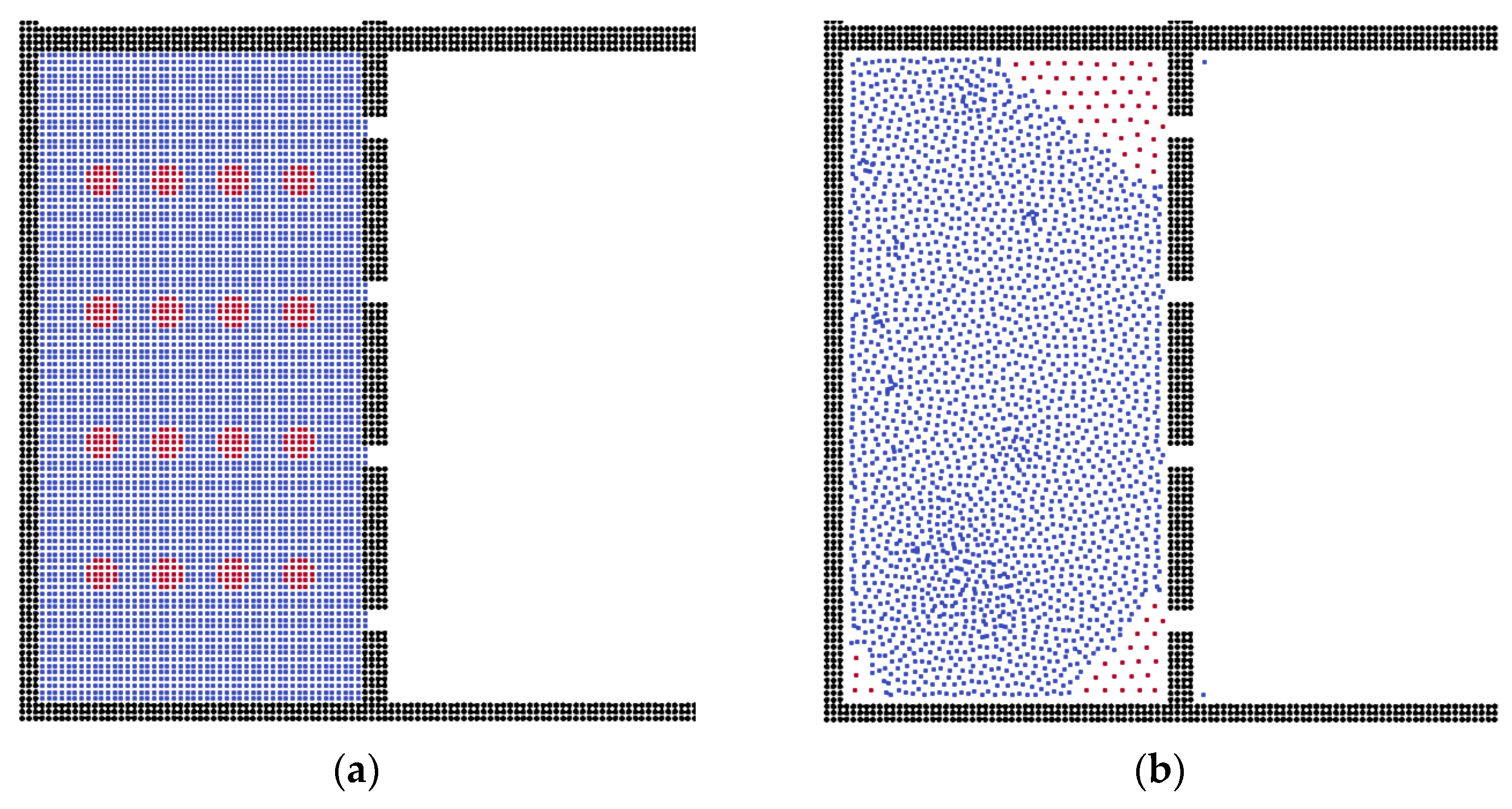
3.1. Scheme Validation

By utilizing the SPH method, we calculated the oil–water separation via flat membrane. The fluid model was constructed with sixteen oil droplets and an aquifer environment, which was driven by a constant acceleration force. The two-phase validation model and separation model are shown in Figure 1, where the red and blue particles are built as the oil and water phases, respectively, and the black particles represent the solid wall.
Because of the effect of surface tension, the oil-in-water state commonly performs as the sphere droplet, and the shape of the oil droplets in water is adopted. In the first fifteen steps, the oil droplets move to the membrane pores gradually, as shown in Figure 2, during which process the oil droplets combine together to form bigger oil clusters, making it harder to flow through the membrane channels.
As can be seen in Figure 2, after 30 steps, the oil clusters accumulate on the surface of the membrane due to the surface tension. In the flat membrane system, the oil droplets can pass through the membrane easily, and the oil particles, which cannot be further excluded, adsorb on the corner of the box. Therefore, the flat membrane can separate small-size oil droplets, which agrees well with previous work [53]. When the droplets gather into bigger oil clusters, the membrane becomes blocked, but this shows a good separation boundary within the waste water domain [54]; afterwards, the oil clusters move and adsorb on the corner of the system due to the lower surface energy.

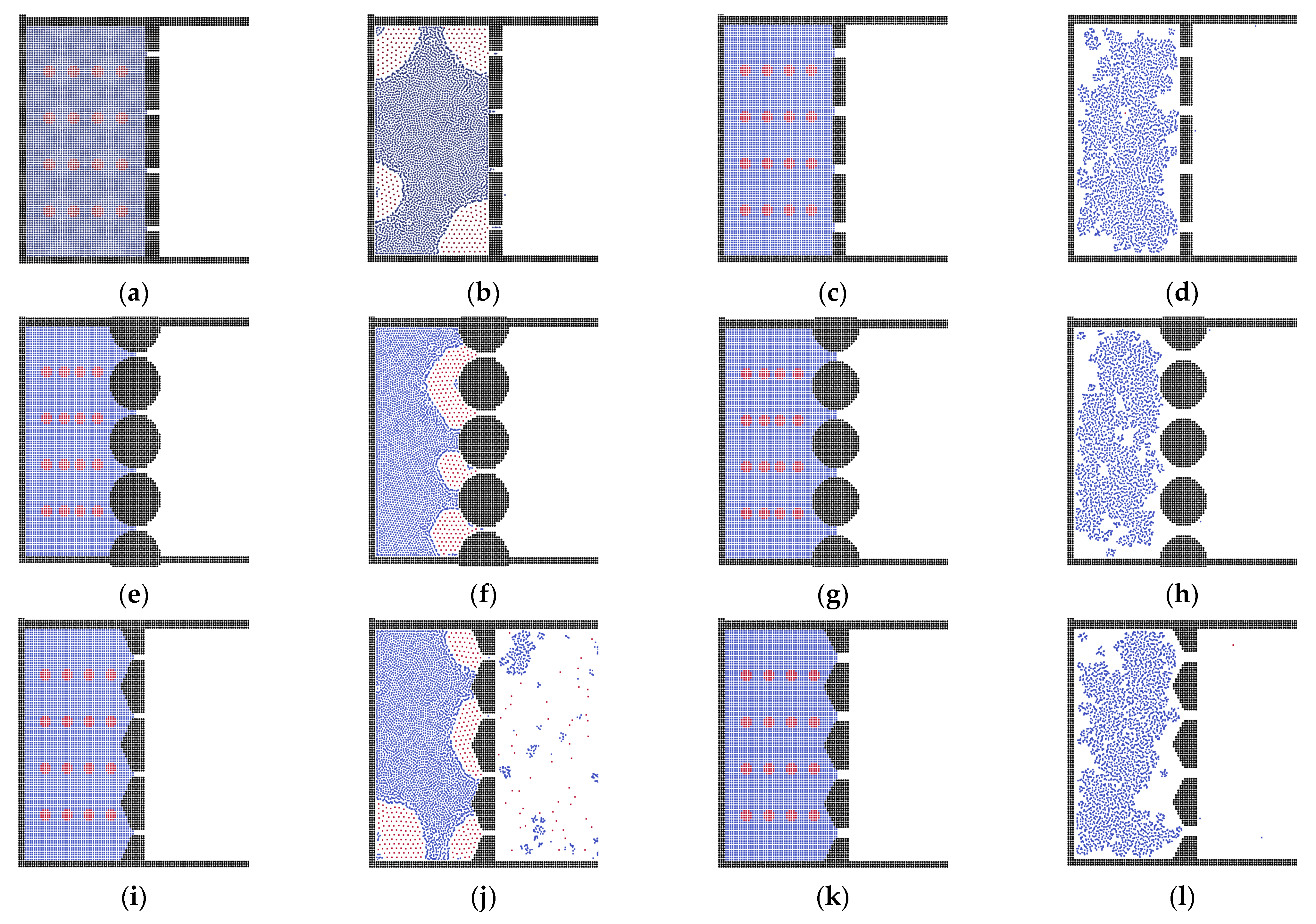
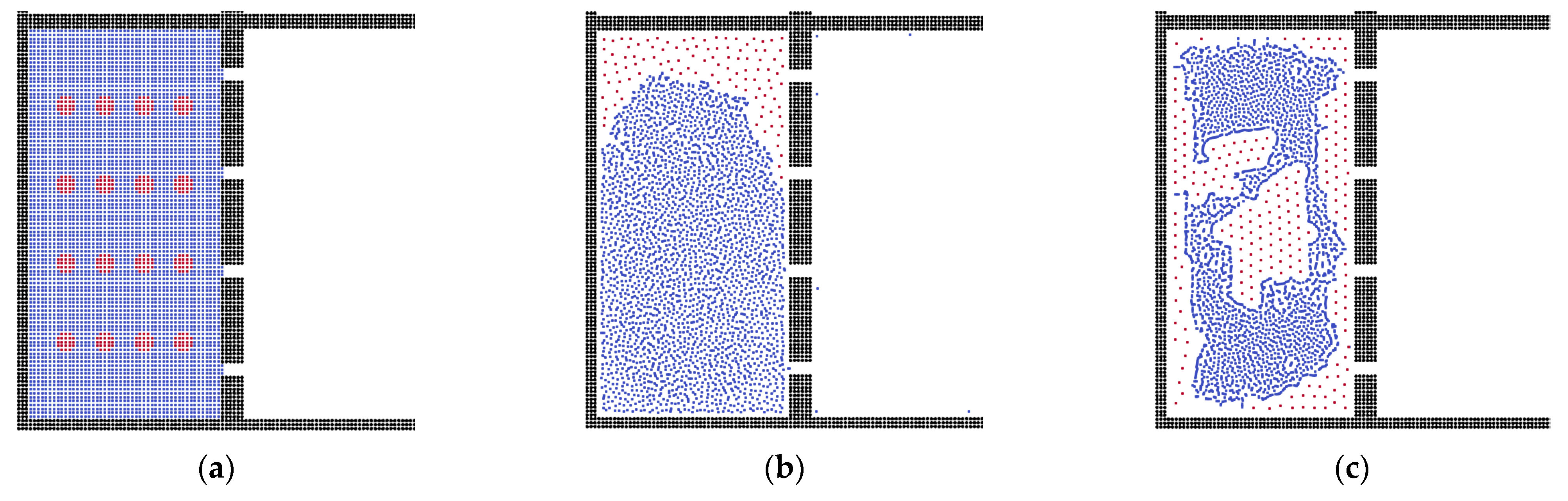
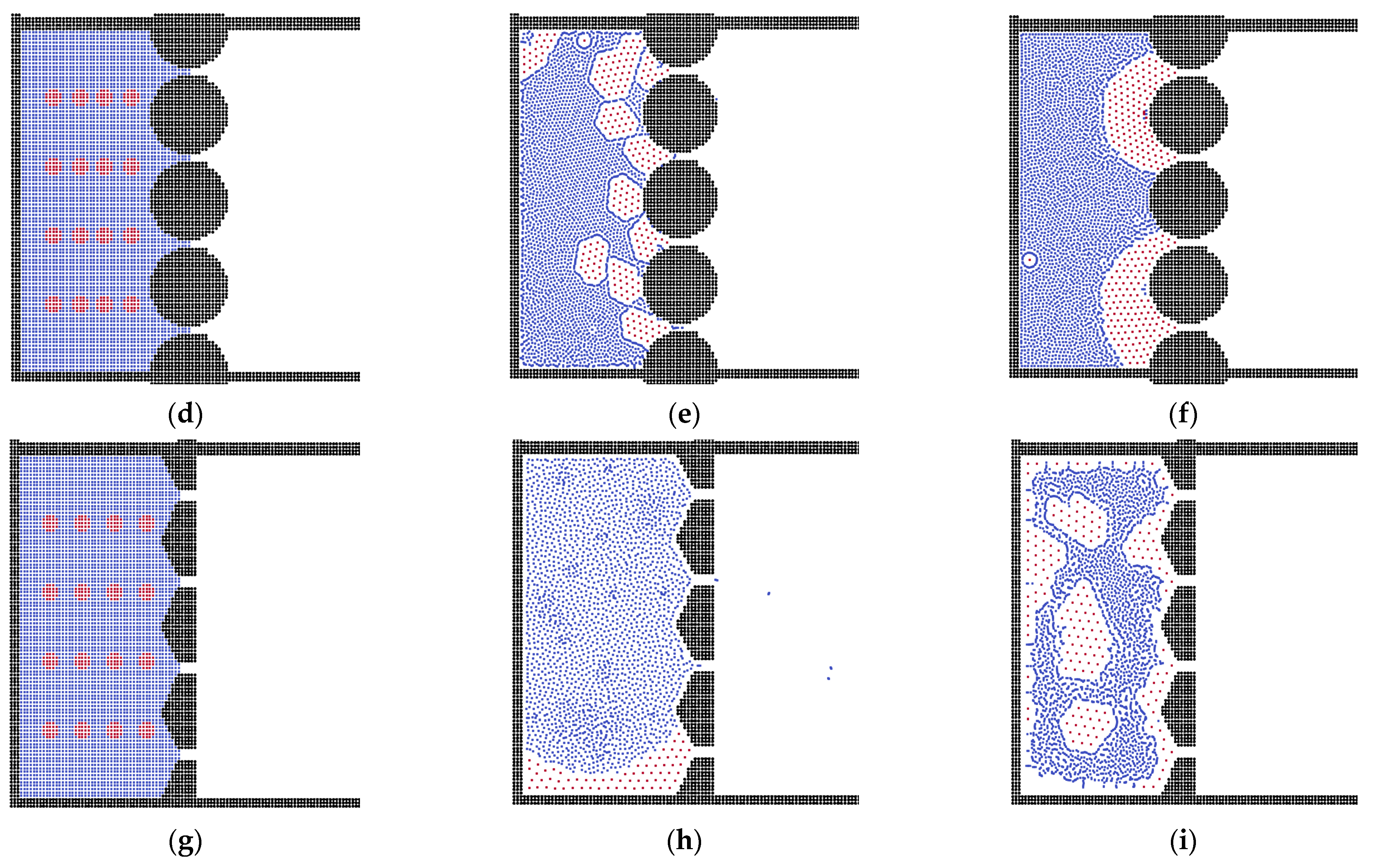
3.2. The Effects of Membrane Structures

Different polymeric membranes have been used for oil–water separation [55], but in this part of the study, in order to examine the effects of membrane structure, membranes in spherical and triangular shape were constructed. Figure 3 demonstrates the processes of separation in different time steps. Initially, the small oil droplets move to the membrane channels, as in previous results, and some small oil droplets pass the channels before changing into bigger clusters. However, the channel size is so small that the small oil droplets combine together quickly before flowing out. Finally, the oil clusters are formed and block the channels [56]. This is because the sphere shape has a larger contact area with the oil clusters, suggesting that it induces less surface energy for the oil phase. Thus, the channels are blocked totally by oil clusters.
For the triangular membrane structure, the separation result is similar to that of the sphere membrane system. The difference emerges in the final stage: the oil phase forms the oil layer on the membrane surface, stopping further fluid flow, as shown in Figure 4. The reason is that the contact area is controlled by the shape of the membrane. If the shape of the membrane facilitates the connectivity of oil clusters, the oil phase will form an oil layer to block the membrane; otherwise, they will block the channels independently.
To investigate the effect of channel width, as shown in Figure 5, we set models with different channel sizes. In the flat membrane system, the smaller channels hold more oil particles in the box, while in the membrane with a wider channel, the entire oil phase is pushed out. This is the same in the sphere and triangular membrane systems. However, in the small-size channel system, the sphere and triangular membranes block the oil phase, because the small pore size results in a stronger interaction between fluid particles and pores.
The fluid flow was affected by the channel surface, and we calculated different models in order to explain the effects of membrane thickness. For the thin membrane structure, as shown in Figure 6, oil particles adsorb on the corner, which is similar to that previously discussed. However, using a thicker membrane structure, Figure 6d shows more residual oil particles, and the structure of the oil phase tends to form a layer. This is because the thicker membrane induces the stronger interaction force between fluid and solid wall particles.

3.3. Oil Properties on the Separation Behavior

To investigate the effect of oil droplet size, we studied the oil droplets with different radii in three shapes of membrane model, as can be seen in Figure 7. Apart from the oil size and the membrane structure, other parameters were kept constant, such as the width of channel, thickness of membrane, viscosity of oil phase and acceleration force. In the flat membrane system, obviously, the size of oil droplets only affected the quantity of residual oil particles. In the sphere membrane system, the small oil droplets can pass the channel easily, meaning they have to accumulate into bigger oil clusters to block the system, as shown in Figure 7f. But for the bigger oil droplets, they do not need to be accumulated into clusters, because the channels only need one droplet to be blocked, as can be seen in Figure 7h. For the triangular membrane system, the channel cannot be blocked by small oil droplets, even if they are merged. But for the bigger oil droplets, they can totally block the membrane channels, performing as the oil layer around the box, and the liquid state is changed to water in oil.
To examine the effect of oil viscosity, as shown in Figure 8, oil droplets with different viscosities were examined. As we discussed, the oil particles would remain in the corner of the system because there was less surface energy. Thus, the residual oil particles always stayed in the same place. In the membrane system with higher oil viscosity, the oil particles tended to adsorb on the membrane surface.

3.4. Analysis of External Force and State of Liquid

As shown in Figure 9, in the flat membrane system, there are more residual oil particles in the box under the condition of a smaller driving force. If we used a stronger external force on the fluid particles, the oil particles accumulated on the membrane surface quickly, blocking the channels. In the sphere membrane system, the oil droplets in both models blocked the channels. The difference is that the stronger driving force led to bigger oil clusters on the membrane surface. In the model of triangular membrane, the results are similar to those of the flat model, but there are fewer oil particles due to its conductivity.
As shown in Figure 10, we also studied the influence of oil–water state behaviors. If we replace the oil droplets in the water phase into water droplets in the oil phase, the water particles cannot go through the channel easily, because the surface tension stops them from getting out of the box. Here, the oil phase particles can pass freely through the channels compared with the oil-in-water system. Finally, the effects of different parameters on the oil–water separation are summarized in Table 2, and we demonstrated that the triangular membrane was the better choice.

4. Conclusions

In this work, we studied oil–water separation in membrane systems, using the SPH method. Compared with bulk phase particles, due to the effect of surface tension, the oil droplets showed stronger resistance in the processes of passing the membrane channels. With regard to the shape of membranes, the flat membrane structure showed less selectivity for water and oil. The sphere membrane facilitated accumulation of the oil phase, due to its larger contact area with oil phase. Different from the low selectivity in the flat membrane and excessive selectivity in the sphere membrane, the triangular membrane structure proved good for accumulation with a better conductivity. The flow ability demonstrated a positive relationship with the width of channel, while it was negative for the thickness of the membrane. By increasing the external force on the fluid particles, the flow ability of liquid was able to be improved, but it also induced the quick accumulation of oil particles and blocked the channels accordingly. Higher oil viscosity led to the oil layer on the membrane surface, preventing the oil–water separation, though it promoted the accumulation of the oil phase. The smaller oil droplets always showed a good passing ability, while bigger oil droplets tended to form clusters and adsorb on the membrane surface, especially for the sphere and triangular membranes. Considering the different effects, the triangular membrane is the better choice because it is insensitive to the inhibiting factors. This work provides a comprehensive study of the effects of various membrane structures on oil–water separation, although we do not consider the effect of electrostatic behavior, which may be studied in our future research.

Author Contributions

Conceptualization, J.L. and S.S.; methodology, J.L. and S.S.; software, J.L. and Q.M.; validation, J.L. and X.X.; formal analysis, J.L. and Q.M.; investigation, J.L. and S.S.; resources, J.L. and S.S.; data curation, J.L.; writing—original draft preparation, J.L.; writing—review and editing, J.L. and X.X.; visualization, J.L.; supervision, S.S.; project administration, S.S.; funding acquisition, S.S. All authors have read and agreed to the published version of the manuscript.

Funding

This work was funded by the National Natural Scientific Foundation of China (Grants No. 51874262, 51936001 and 12171340) and King Abdullah University of Science and Technology (KAUST) through the grants BAS/1/1351-01, URF/1/4074-01, and URF/1/3769-01.

Institutional Review Board Statement

Not applicable.

Informed Consent Statement

Not applicable.

Data Availability Statement

Not applicable.

Acknowledgments

We would like to express appreciation for all authors.

Conflicts of Interest

The authors declare no conflict of interest.

References

  1. Yang, Y.; Yao, J.; Wang, C.; Gao, Y.; Zhang, Q.; An, S.; Song, W. New pore space characterization method of shale matrix formation by considering organic and inorganic pores. J. Nat. Gas Sci. Eng. 2015, 27, 496–503. [Google Scholar] [CrossRef]
  2. Yang, Y.; Li, Y.; Yao, J.; Iglauer, S.; Luquot, L.; Zhang, K.; Sun, H.; Zhang, L.; Song, W.; Wang, Z. Dynamic pore-scale dissolution by CO2-saturated brine in carbonates: Impact of homogeneous versus fractured versus vuggy pore structure. Water Resour. Res. 2020, 56, e2019WR026112. [Google Scholar] [CrossRef]
  3. Zhang, T.; Li, Y.; Sun, S. Phase equilibrium calculations in shale gas reservoirs. Capillarity 2019, 2, 8–16. [Google Scholar] [CrossRef] [Green Version]
  4. Cai, J.; Hajibeygi, H.; Yao, J.; Hassanizadeh, M. Advances in porous media science and engineering from InterPore2020 perspective. Adv. Geo-Energy Res. 2020, 4, 352–355. [Google Scholar] [CrossRef]
  5. Zhang, T.; Sun, S. A coupled Lattice Boltzmann approach to simulate gas flow and transport in shale reservoirs with dynamic sorption. Fuel 2019, 246, 196–203. [Google Scholar] [CrossRef]
  6. Zhang, T.; Sun, S.; Song, H. Flow mechanism and simulation approaches for shale gas reservoirs: A review. Transp. Porous Media 2019, 126, 655–681. [Google Scholar] [CrossRef] [Green Version]
  7. Chen, H.; Kou, J.; Sun, S.; Zhang, T. Fully mass-conservative IMPES schemes for incompressible two-phase flow in porous media. Comput. Methods Appl. Mech. Eng. 2019, 350, 641–663. [Google Scholar] [CrossRef]
  8. Dawson, C.; Sun, S.; Wheeler, M.F. Compatible algorithms for coupled flow and transport. Comput. Methods Appl. Mech. Eng. 2004, 193, 2565–2580. [Google Scholar] [CrossRef]
  9. Moortgat, J.; Sun, S.; Firoozabadi, A. Compositional modeling of three-phase flow with gravity using higher-order finite element methods. Water Resour. Res. 2011, 47, W0551. [Google Scholar] [CrossRef] [Green Version]
  10. Zhang, T.; Li, Y.; Li, Y.; Sun, S.; Gao, X. A self-adaptive deep learning algorithm for accelerating multi-component flash calculation. Comput. Methods Appl. Mech. Eng. 2020, 369, 113207. [Google Scholar] [CrossRef]
  11. Zhang, T.; Sun, S. Thermodynamics-Informed Neural Network (TINN) for Phase Equilibrium Calculations Considering Capillary Pressure. Energies 2021, 14, 7724. [Google Scholar] [CrossRef]
  12. Yang, Y.; Zhou, Y.; Blunt, M.J.; Yao, J.; Cai, J. Advances in multiscale numerical and experimental approaches for multiphysics problems in porous media. Adv. Geo-Energy Res. 2021, 5, 233–238. [Google Scholar] [CrossRef]
  13. Hua, J.; Stene, J.F.; Lin, P. Numerical simulation of 3D bubbles rising in viscous liquids using a front tracking method. J. Comput. Phys. 2008, 227, 3358–3382. [Google Scholar] [CrossRef] [Green Version]
  14. Zhao, Y.; Tan, H.H.; Zhang, B. A high-resolution characteristics-based implicit dual time-stepping VOF method for free surface flow simulation on unstructured grids. J. Comput. Phys. 2002, 183, 233–273. [Google Scholar] [CrossRef]
  15. Li, H.; Yap, Y.; Lou, J.; Shang, Z. Numerical modelling of three-fluid flow using the level-set method. Chem. Eng. Sci. 2015, 126, 224–236. [Google Scholar] [CrossRef]
  16. Bui, H.H.; Fukagawa, R.; Sako, K.; Ohno, S. Lagrangian meshfree particles method (SPH) for large deformation and failure flows of geomaterial using elastic–plastic soil constitutive model. Int. J. Numer. Anal. Methods Geomech. 2008, 32, 1537–1570. [Google Scholar] [CrossRef]
  17. Kong, J.; Li, K. Oil removal from oil-in-water emulsions using PVDF membranes. Sep. Purif. Technol. 1999, 16, 83–93. [Google Scholar] [CrossRef]
  18. Abadi, S.R.H.; Sebzari, M.R.; Hemati, M.; Rekabdar, F.; Mohammadi, T. Ceramic membrane performance in microfiltration of oily wastewater. Desalination 2011, 265, 222–228. [Google Scholar] [CrossRef]
  19. Cheryan, M.; Rajagopalan, N. Membrane processing of oily streams. Wastewater treatment and waste reduction. J. Membr. Sci. 1998, 151, 13–28. [Google Scholar] [CrossRef]
  20. Padaki, M.; Murali, R.S.; Abdullah, M.S.; Misdan, N.; Moslehyani, A.; Kassim, M.; Hilal, N.; Ismail, A. Membrane technology enhancement in oil–water separation. A review. Desalination 2015, 357, 197–207. [Google Scholar] [CrossRef]
  21. Singh, V.; Purkait, M.; Das, C. Cross-flow microfiltration of industrial oily wastewater: Experimental and theoretical consideration. Sep. Sci. Technol. 2011, 46, 1213–1223. [Google Scholar] [CrossRef]
  22. Wang, H.; Yuan, X.; Liang, H.; Chai, Z.; Shi, B. A brief review of the phase-field-based lattice Boltzmann method for multiphase flows. Capillarity 2019, 2, 33–52. [Google Scholar] [CrossRef] [Green Version]
  23. Lucy, L.B. A numerical approach to the testing of the fission hypothesis. Astron. J. 1977, 82, 1013–1024. [Google Scholar] [CrossRef]
  24. Gingold, R.A.; Monaghan, J.J. Smoothed particle hydrodynamics: Theory and application to non-spherical stars. Mon. Not. R. Astron. Soc. 1977, 181, 375–389. [Google Scholar] [CrossRef]
  25. Amicarelli, A.; Albano, R.; Mirauda, D.; Agate, G.; Sole, A.; Guandalini, R. A Smoothed Particle Hydrodynamics model for 3D solid body transport in free surface flows. Comput. Fluids 2015, 116, 205–228. [Google Scholar] [CrossRef]
  26. Liu, M.; Liu, G.; Lam, K.; Zong, Z. Smoothed particle hydrodynamics for numerical simulation of underwater explosion. Comput. Mech. 2003, 30, 106–118. [Google Scholar] [CrossRef]
  27. Mayrhofer, A.; Laurence, D.; Rogers, B.; Violeau, D. DNS and LES of 3-D wall-bounded turbulence using smoothed particle hydrodynamics. Comput. Fluids 2015, 115, 86–97. [Google Scholar] [CrossRef]
  28. Shadloo, M.S.; Oger, G.; Le Touzé, D. Smoothed particle hydrodynamics method for fluid flows, towards industrial applications: Motivations, current state, and challenges. Comput. Fluids 2016, 136, 11–34. [Google Scholar] [CrossRef]
  29. He, M.; Khayyer, A.; Gao, X.; Xu, W.; Liu, B. Theoretical method for generating solitary waves using plunger-type wavemakers and its Smoothed Particle Hydrodynamics validation. Appl. Ocean Res. 2021, 106, 102414. [Google Scholar] [CrossRef]
  30. Crespo, A.; Altomare, C.; Domínguez, J.; González-Cao, J.; Gómez-Gesteira, M. Towards simulating floating offshore oscillating water column converters with smoothed particle hydrodynamics. Coast. Eng. 2017, 126, 11–26. [Google Scholar] [CrossRef]
  31. Chen, Y.-k.; Meringolo, D.D.; Liu, Y. SPH study of wave force on simplified superstructure of open-type sea access road. Ocean Eng. 2022, 249, 110869. [Google Scholar] [CrossRef]
  32. Yang, Q.; Yao, J.; Huang, Z.; Asif, M. A comprehensive SPH model for three-dimensional multiphase interface simulation. Comput. Fluids 2019, 187, 98–106. [Google Scholar] [CrossRef]
  33. Yang, Q.; Yao, J.; Huang, Z.; Zhu, G.; Liu, L.; Song, W. Pore-scale investigation of petro-physical fluid behaviours based on multiphase SPH method. J. Pet. Sci. Eng. 2020, 192, 107238. [Google Scholar] [CrossRef]
  34. Fatehi, R.; Manzari, M. A consistent and fast weakly compressible Smoothed Particle Hydrodynamics with a new wall boundary condition. Int. J. Numer. Methods Fluids 2012, 68, 905–921. [Google Scholar] [CrossRef]
  35. Fatehi, R.; Manzari, M. A remedy for numerical oscillations in weakly compressible smoothed particle hydrodynamics. Int. J. Numer. Methods Fluids 2011, 67, 1100–1114. [Google Scholar] [CrossRef]
  36. He, X.; Luo, L.-S. Lattice Boltzmann model for the incompressible Navier–Stokes equation. J. Stat. Phys. 1997, 88, 927–944. [Google Scholar] [CrossRef]
  37. Mohd-Yusof, J. Combined immersed-boundary/B-spline methods for simulations of flow in complex geometries. Cent. Turbul. Res. Annu. Res. Briefs 1997, 161, 317–327. [Google Scholar]
  38. Tartakovsky, A.M.; Meakin, P. Pore scale modeling of immiscible and miscible fluid flows using smoothed particle hydrodynamics. Adv. Water Resour. 2006, 29, 1464–1478. [Google Scholar] [CrossRef]
  39. Tartakovsky, A.M.; Panchenko, A. Pairwise force smoothed particle hydrodynamics model for multiphase flow: Surface tension and contact line dynamics. J. Comput. Phys. 2016, 305, 1119–1146. [Google Scholar] [CrossRef] [Green Version]
  40. Chen, T.; Chiu, M.-S.; Weng, C.-N. Derivation of the generalized Young-Laplace equation of curved interfaces in nanoscaled solids. J. Appl. Phys. 2006, 100, 074308. [Google Scholar] [CrossRef] [Green Version]
  41. Liu, H.; Cao, G. Effectiveness of the Young-Laplace equation at nanoscale. Sci. Rep. 2016, 6, 1–10. [Google Scholar] [CrossRef]
  42. Liu, M.; Liu, G. Smoothed particle hydrodynamics (SPH): An overview and recent developments. Arch. Comput. Methods Eng. 2010, 17, 25–76. [Google Scholar] [CrossRef] [Green Version]
  43. Violeau, D.; Rogers, B.D. Smoothed particle hydrodynamics (SPH) for free-surface flows: Past, present and future. J. Hydraul. Res. 2016, 54, 1–26. [Google Scholar] [CrossRef]
  44. Zhu, Y.; Fox, P.J. Simulation of pore-scale dispersion in periodic porous media using smoothed particle hydrodynamics. J. Comput. Phys. 2002, 182, 622–645. [Google Scholar] [CrossRef]
  45. Price, D.J. Smoothed particle hydrodynamics and magnetohydrodynamics. J. Comput. Phys. 2012, 231, 759–794. [Google Scholar] [CrossRef] [Green Version]
  46. Monaghan, J.J. Smoothed particle hydrodynamics. Annu. Rev. Astron. Astrophys. 1992, 30, 543–574. [Google Scholar] [CrossRef]
  47. Morris, J.P.; Fox, P.J.; Zhu, Y. Modeling low Reynolds number incompressible flows using SPH. J. Comput. Phys. 1997, 136, 214–226. [Google Scholar] [CrossRef]
  48. Zhu, Y.; Fox, P.J.; Morris, J.P. A pore-scale numerical model for flow through porous media. Int. J. Numer. Anal. Methods Geomech. 1999, 23, 881–904. [Google Scholar] [CrossRef]
  49. Tartakovsky, A.M.; Trask, N.; Pan, K.; Jones, B.; Pan, W.; Williams, J.R. Smoothed particle hydrodynamics and its applications for multiphase flow and reactive transport in porous media. Comput. Geosci. 2016, 20, 807–834. [Google Scholar] [CrossRef] [Green Version]
  50. Liu, J.; Yang, Y.; Sun, S.; Yao, J.; Kou, J. Flow Behaviors of Shale Oil in Kerogen Slit by Molecular Dynamics Simulation. Chem. Eng. J. 2022, 434, 134682. [Google Scholar] [CrossRef]
  51. Yang, Y.; Liu, J.; Yao, J.; Kou, J.; Li, Z.; Wu, T.; Zhang, K.; Zhang, L.; Sun, H. Adsorption behaviors of shale oil in kerogen slit by molecular simulation. Chem. Eng. J. 2020, 387, 124054. [Google Scholar] [CrossRef]
  52. Liu, J.; Zhao, Y.; Yang, Y.; Mei, Q.; Yang, S.; Wang, C. Multicomponent Shale Oil Flow in Real Kerogen Structures via Molecular Dynamic Simulation. Energies 2020, 13, 3815. [Google Scholar] [CrossRef]
  53. Ko, S.; Prigiobbe, V.; Huh, C.; Bryant, S.; Bennetzen, M.V.; Mogensen, K. Accelerated Oil Droplet Separation from Produced Water Using Magnetic Nanoparticles. In Proceedings of the SPE Annual Technical Conference and Exhibition, Amsterdam, The Netherlands, 27–29 October 2014; OnePetro: Richardson, TX, USA, 2014. [Google Scholar]
  54. Finborud, A.; Faucher, M.; Sellman, E. New Method for Improving Oil Droplet Growth for Separation Enhancement. In Proceedings of the SPE Annual Technical Conference and Exhibition, Houston, TX, USA, 3–6 October 1999; OnePetro: Richardson, TX, USA, 1999. [Google Scholar]
  55. Dmitrieva, E.S.; Anokhina, T.S.; Novitsky, E.G.; Volkov, V.V.; Borisov, I.L.; Volkov, A.V. Polymeric Membranes for Oil-Water Separation: A Review. Polymers 2022, 14, 980. [Google Scholar] [CrossRef]
  56. Wang, Y.; Kang, Y.; Wang, D.; You, L.; Chen, M.; Yan, X. Liquid phase blockage in micro-nano capillary pores of tight condensate reservoirs. Capillarity 2022, 5, 12–22. [Google Scholar] [CrossRef]
Figure 1. (a) The two-phase validation model and (b) the physical model of oil–water separation. Black particles represent the solid wall and membrane, blue particles represent the water phase, and red particles represent the oil phase.
Membranes 12 00387 g001
Figure 2. The separation processes during different time steps. (a) Step = 5, (b) Step = 20, (c) Step = 100, (d) Step = 200.
Membranes 12 00387 g002
Figure 3. The separation processes in the sphere membrane during different time steps. (a) Step = 0, (b) Step = 20, (c) Step = 100, (d) Step = 200.
Membranes 12 00387 g003
Figure 4. The separation processes in the triangular membrane during different time steps. (a) Step = 0, (b) Step = 20, (c) Step = 100, (d) Step = 200.
Membranes 12 00387 g004
Figure 5. The results with different channel sizes; (a,b,e,f,i,j) with channel width of 12 μm; (c,d,g,h,k,l) and with channel width of 20 μm.
Membranes 12 00387 g005
Figure 6. Results of separation with different thicknesses of membrane, (a,c) are the initial conditions, thickness = 10 and 30 μm, respectively; (b,d) are the results.
Membranes 12 00387 g006aMembranes 12 00387 g006b
Figure 7. The different oil droplet size systems in membrane for the oil–water separation, (a,b,e,f,i,j) forming oil droplets with radii of 4 μm; (c,d,g,h,k,l) forming oil droplets with radii of 8 μm.
Membranes 12 00387 g007aMembranes 12 00387 g007b
Figure 8. Results of separation with different oil viscosities: (a) 0.2 mPa·s; (b) 0.4 mPa·s; (c) 0.8 mPa·s.
Membranes 12 00387 g008
Figure 9. Results with different driving forces: (a,d,g) initial conditions of three different shape membrane systems; (b,e,h) controlled with 0.0005 m·s−2; and (c,f,i) controlled with 0.0015 m·s−2.
Membranes 12 00387 g009aMembranes 12 00387 g009b
Figure 10. (a) The initial condition of water in oil. (b) The separation result for water in oil system. The red particles represent the oil phase and the blue particles represent the water phase.
Membranes 12 00387 g010
Table 2. Evaluation of oil–water separation with different parameters.
Pore SizeThicknessDroplet SizeViscosityExternal Force
Flat
Triangular
Sphere
↑: Facilitation, ↓: Inhibition, ↔: Insensitive.
Publisher’s Note: MDPI stays neutral with regard to jurisdictional claims in published maps and institutional affiliations.

