
Membrane Water Treatment for Drinking Water Production from an Industrial Effluent Used in the Manufacturing of Food Additives

 ,
,
Abstract
:
1. Introduction
2. Materials and Methods
2.1. Materials
2.2. Physicochemical Characterization of the Industrial Effluent
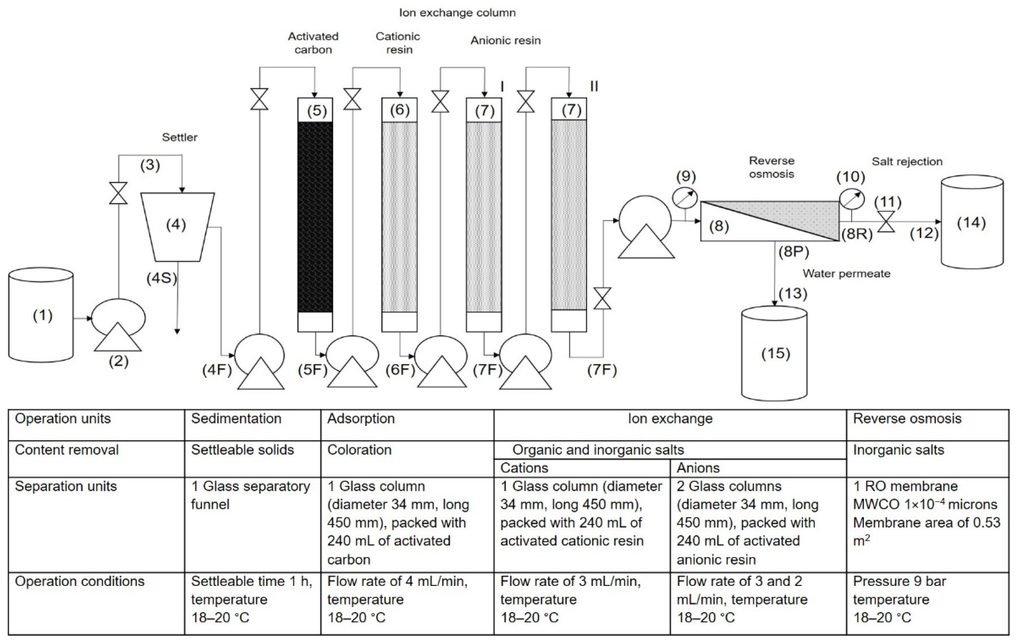
2.3. Membrane Treatment Process Applied to Industrial Effluent for Water Recovery
2.4. Experimental Determination of Rupture Curves in Adsorption and Ion Exchange Columns
2.5. Determination of Effectiveness of RO Membrane for Water Recovery from the Industrial Effluent
3. Results
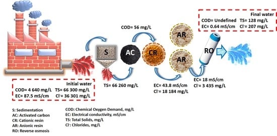
3.1. Water Recovery by Industrial Effluent Treatment
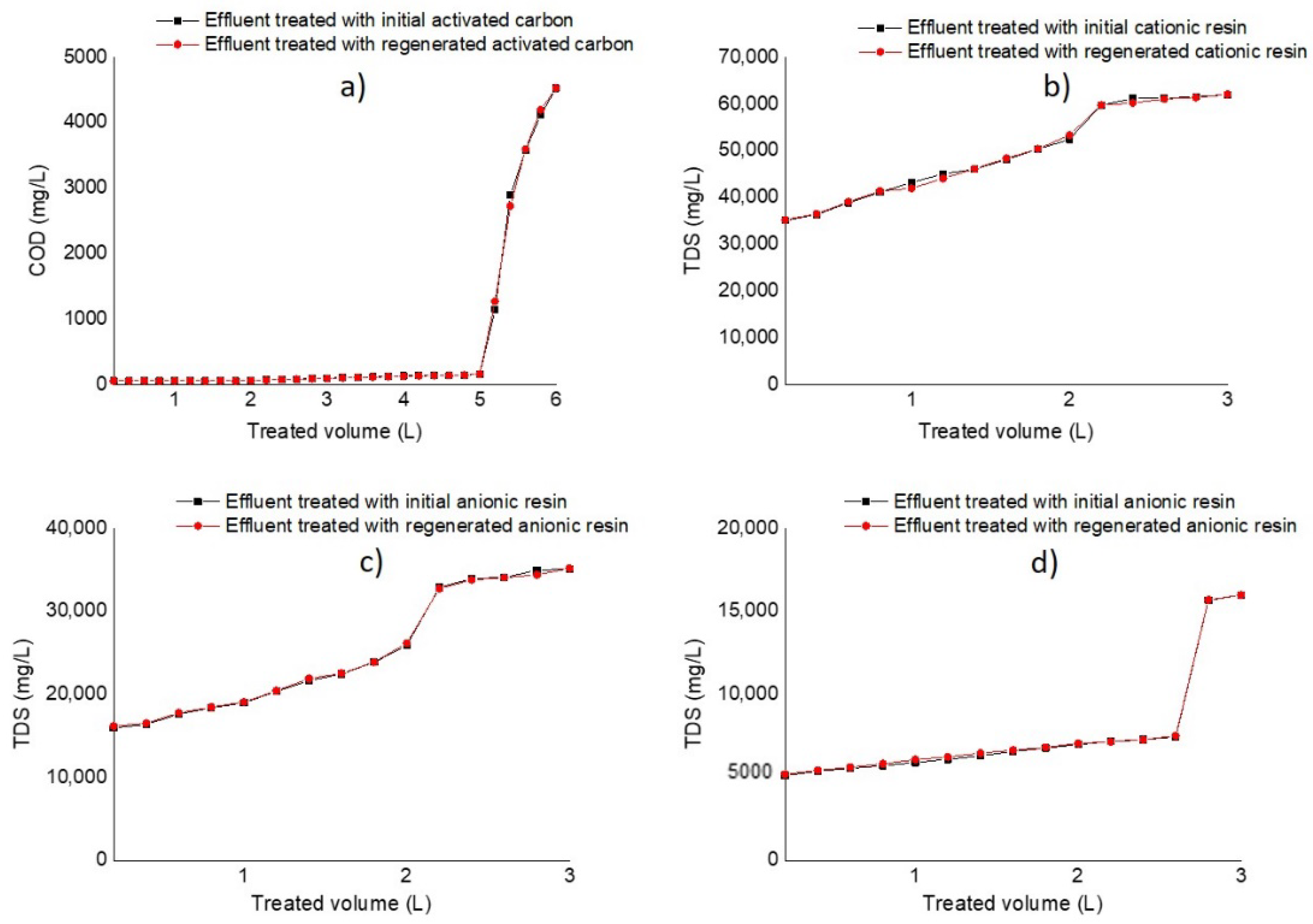
3.2. Rupture Curves in Adsorption and Ion Exchange Columns
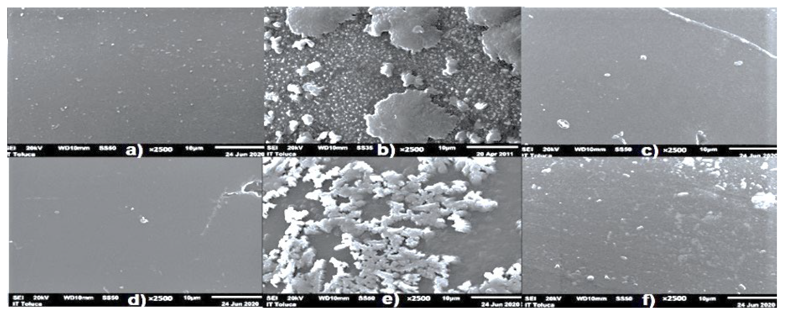
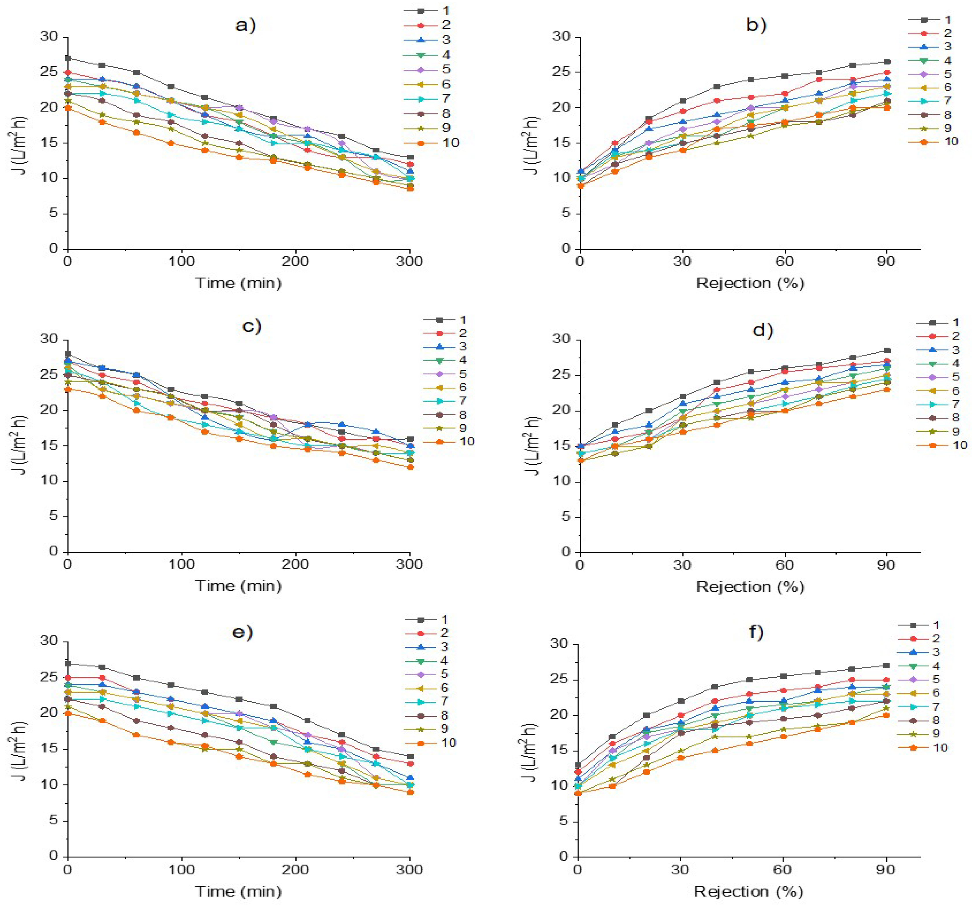
3.3. Membrane Efficiency in the Desalination Process of an Industrial Effluent
4. Conclusions
Author Contributions
Funding
Institutional Review Board Statement
Informed Consent Statement
Data Availability Statement
Acknowledgments
Conflicts of Interest
Acronyms
| AC | Activated carbon |
| C | Coagulation |
| C/F | Coagulation/flocculation |
| Cb | Concentration at the breakthrough time, mg/L |
| Cl− | Chlorides, mg/L |
| Co | Initial concentration of effluent, mg/L |
| COD | Chemical Oxygen Demand, mg/L |
| CP | Concentration polarization |
| Cp | Total Dissolved Solids concentration in permeate water, mg/L |
| E | Electrochemical |
| EC | Electrocoagulation |
| EC | Electrical conductivity, mS/cm |
| EPA | Environmental Protection Agency |
| FO | Forward osmosis |
| GAC | Granular activated carbon adsorption |
| IEXR | Ion exchange resins |
| IMBR | Integrated membrane system with a bioreactor |
| J | Water permeate fluxes, L/h/m2 |
| Jp | Water flux, L/m2/h |
| Jw | Clean water flux prior to wastewater treatment, L/m2/h |
| Jwi | Water flux after the removal of fouling by washing the membrane, L/m2/h |
| MBR | Membrane bioreactors |
| MD | Membrane distillation |
| MF | Microfiltration |
| NF | Nanofiltration |
| WHO | World Health Organization |
| OO | Ozone oxidation |
| Q | Volumetric flow in the column, mL/min |
| qb1 | Mass of component removal per volume of packaging at rupture point, mg/mL |
| qb2 | Mass of component removal per packaging material mass at rupture point, mg/g |
| Rir | Hydraulic resistance after the removal of fouling by washing the membrane |
| Rm | Hydraulic resistance prior to wastewater treatment |
| RO | Reverse osmosis |
| Rr | Hydraulic resistance due to reversible fouling |
| Rs | Rejection percentage |
| Rt | Resistance following wastewater treatment |
| S | Sedimentation |
| SDI | Silt Density Index |
| SEM | Scanning Electron Microscopy |
| SF | Sand filtration |
| SS | Settleable Solids, mL/L |
| TDS | Total Dissolved Solids, mg/L |
| TMP | Transmembrane pressure, bar |
| TS | Total Solids, mg/L |
| UF | Ultrafiltration |
| Vb | Volumes of the treated effluent at rupture points, L |
| Vm | Bed volume of the packaging material in the column, mL |
| WWTP | Wastewater treatment plant |
| WWTPs | Wastewater treatment plants |
| θb | Breakthrough time, h |
| µe | Viscosity of the effluent, cp |
| µw | Viscosity of the effluent, cp |
References
- UNU-INWEH. Water Security & the Global Water Agenda, The UN-Water Analytical Brief. 2013. Available online: https://sdg.iisd.org/news/un-water-brief-defines-water-security/ (accessed on 10 March 2022).
- Lin, S.; Zhao, H.; Zhu, L.; He, T.; Chen, S.; Gao, C.; Lin, Z. Seawater desalination technology and engineering in China: A review. Desalination 2021, 498, 114728. [Google Scholar] [CrossRef]
- Udayakumar, S.; Praveen, K. Chapter 16—Advancements in industrial wastewater treatment by integrated membrane technologies. In Integrated Environmental Technologies for Wastewater Treatment and Sustainable Development; Vineet, K., Manish, K., Eds.; Elsevier: Amsterdam, The Netherlands, 2022; pp. 369–382. [Google Scholar] [CrossRef]
- Adam, M.R.; Othman, M.H.D.; Kurniawan, T.A.; Puteh, M.H.; Ismail, A.F.; Khongnakorn, W.; Rahman, M.A.; Jaafar, J. Advances in Adsorptive Membrane Technology for Water Treatment and Resource Recovery Applications: A Critical Review. J. Environ. Chem. Eng. 2022, 10, 107633. [Google Scholar] [CrossRef]
- Hernández, K.; Muro, C.; Ortega, R.E.; Velazquez, S.; Riera, F. Water recovery by treatment of food industry-wastewater using membrane processes. Environ. Technol. 2021, 42, 775–788. [Google Scholar] [CrossRef] [PubMed]
- Ang, W.L.; Mohammad, A.W.; Johnson, D.; Hilal, N. Forward osmosis research trends in desalination and wastewater treatment: A review of research trends over the past decade. J. Water Process. Eng. 2019, 31, 100886. [Google Scholar] [CrossRef]
- Singh, S.K.; Sharma, C.; Abhijit, M. A comprehensive review of standalone and hybrid forward osmosis for water treatment: Membranes and recovery strategies of draw solutions. J. Environ. Chem. Eng. 2021, 9, 105473. [Google Scholar] [CrossRef]
- Hildebrand, C.; Kuglin, V.B.; Brandão, H.L.; Vilar, V.J.P.; Guelli, S.M.A.; Ulson De Souza, A.A. Insights into nanofiltration of textile wastewaters for water reuse. Clean Technol. Environ. Policy 2014, 16, 591–600. [Google Scholar] [CrossRef]
- Ahmad, T.; Guria, C. Progress in the modification of polyvinyl chloride (PVC) membranes: A performance review for wastewater treatment. J. Water Process. Eng. 2022, 45, 102466. [Google Scholar] [CrossRef]
- Rosyadah, N.N.; Ang, W.L.; Teow, Y.H.; Mohammad, A.W.; Hilal, N. Nanofiltration membrane processes for water recycling, reuse and product recovery within various industries: A review. J. Water Process. Eng. 2022, 45, 102478. [Google Scholar] [CrossRef]
- Warsinger, D.M.; Chakraborty, S.; Tow, E.W.; Plumlee, M.H.; Bellona, C.; Loutatidou, S.; Karimi, L.; Mikelonis, A.M.; Achilli, A.; Ghassemi, A.; et al. A review of polymeric membranes and processes for potable water reuse. Prog. Polym. Sci. 2018, 81, 209–237. [Google Scholar] [CrossRef]
- Zhang, X.; Huang, J.; Cheng, X.; Chen, H.; Liu, Q.; Yao, P.; Ngo, H.H.; Nghiem, L.D. Mitigation of reverse osmosis membrane fouling by electrochemical-microfiltration-activated carbon pretreatment. J. Membr. Sci. 2022, 656, 120615. [Google Scholar] [CrossRef]
- Ćurić, I.; Dolar, D. Investigation of Pretreatment of Textile Wastewater for Membrane Processes and Reuse for Washing Dyeing Machines. Membranes 2022, 12, 449. [Google Scholar] [CrossRef]
- Partal, R.; Basturk, I.; Hocaoglu, S.M.; Baban, A.; Yilmaz, E. Recovery of water and reusable salt solution from reverse osmosis brine in textile industry: A case study. Water Resour. Ind. 2022, 27, 100174. [Google Scholar] [CrossRef]
- Chen, G.Q.; Wu, Y.H.; Tan, Y.J.; Chen, Z.; Tong, X.; Bai, Y.; Luo, L.W.; Wang, H.B.; Xu, Y.Q.; Zhang, Z.W.; et al. Pretreatment for alleviation of RO membrane fouling in dyeing wastewater reclamation. Chemosphere 2022, 292, 133471. [Google Scholar] [CrossRef]
- Güneş, E.; Gönder, Z.B. Evaluation of the hybrid system combining electrocoagulation, nanofiltration and reverse osmosis for biologically treated textile effluent: Treatment efficiency and membrane fouling. J. Environ. Manag. 2021, 294, 113042. [Google Scholar] [CrossRef]
- Chandrasekhar, S.S.; Vaishnavi, D.; Sahu, N.; Sridhar, S. Design of an integrated membrane bioreactor process for effective and environmentally safe treatment of highly complex coffee industrial effluent. J. Water Process Eng. 2020, 37, 101436. [Google Scholar] [CrossRef]
- Lebron, Y.A.; Moreira, V.R.; Furtado, T.P.; da Silva, S.C.; Lange, L.C.; Amaral, M.C. Vinasse treatment using hybrid tannin-based Coagulation-Microfiltration-Nanofiltration processes: Potential energy recovery, technical and economic feasibility assessment. Sep. Purif. Technol. 2020, 248, 117152. [Google Scholar] [CrossRef]
- Dos Santos, J.D.; Veit, M.T.; Palácio, S.M.; da Cunha Gonçalves, G.; Fagundes-Klen, M.R. Evaluation of the combined process of coagulation/flocculation and microfiltration of Cassava Starch wastewater: Removal efficiency and membrane fouling. Wat. Air Soil Poll. 2017, 228, 238. [Google Scholar] [CrossRef]
- Czuba, K.; Bastrzyk, A.; Rogowska, A.; Janiak, K.; Pacyna, K.; Kossińska, N.; Kita, M.; Chrobot, P.; Podstawczyk, D. Towards the circular economy—A pilot-scale membrane technology for the recovery of water and nutrients from secondary effluent. Sci. Total Environ. 2021, 791, 148266. [Google Scholar] [CrossRef]
- American Public Health Association (APHA). Standard Methods for the Examination of Water and Wastewater, a Joint Publication of the American Public Health Association (APHA), 20th ed.The American Water Works Association (AWWA): Denver, CO, USA; The Water Environment Federation (WEF): Alexandria, VA, USA, 2005. [Google Scholar]
- Panagopoulos, A.; Haralambous, K.J.; Loizidou, M. Desalination brine disposal methods and treatment technologies—A review. Sci. Total Environ. 2019, 693, 133545. [Google Scholar] [CrossRef]
- World Health Organization. Guidelines for Drinking-Water Quality: Fourth Edition Incorporating the First and Second Addenda. Available online: https://www.who.int/publications/i/item/9789240045064 (accessed on 4 April 2022).
- Environmental Protection Agency (EPA). Safe Drinking Water Act (SDWA). Drinking Water Regulations and Contaminants. Available online: https://www.epa.gov/sdwa/drinking-water-regulations-and-contaminants (accessed on 4 April 2022).
- NOM-127-SSA1-1994. Environmental Health. Water for Human Use and Consumption. Permissible Limits of Quality and Treatments to Which the Water Must Be Submitted for Its Purification. Available online: https://www.dof.gob.mx/nota_detalle.php?codigo=2063863&fecha=22/11/2000#gsc.tab=0 (accessed on 5 April 2022).
- Valipour, A.; Hamnabard, N.; Woo, K.S.; Ahn, Y.H. Performance of high-rate constructed phytoremediation process with attached growth for domestic wastewater treatment: Effect of high TDS and Cu. J. Environ. Manag. 2014, 145, 1–8. [Google Scholar] [CrossRef]
- Hassaan, M.A.; Nemr, A.E. Advanced Oxidation Processes for Textile Wastewater Treatment. Int. J. Photochem. Photobiol. 2017, 2, 85–93. [Google Scholar] [CrossRef]
- Yadav, G.; Mishra, A.; Ghosh, P.; Sindhu, R.; Vinayak, V.; Pugazhendhi, A. Technical, economic and environmental feasibility of resource recovery technologies from wastewater. Sci. Total Environ. 2021, 796, 149022. [Google Scholar] [CrossRef]
- Varjani, S.; Rakholiya, P.; Ng, H.Y.; You, S.; Teixeira, J.A. Microbial degradation of dyes: An overview. Bioresour. Technol. 2020, 314, 123728. [Google Scholar] [CrossRef]
- Shabir, M.; Muhammad, Y.; Hussain, M.; Shafiq, I.; Parveen, A.; Nizami, A.S.; Jeon, B.H.; Park, Y.K. A review on recent advances in the treatment of dye-polluted wastewater. J. Ind. Eng. Chem. 2022, in press. [Google Scholar] [CrossRef]
- Zhang, X. Selective separation membranes for fractionating organics and salts for industrial wastewater treatment: Design strategies and process assessment. J. Membr. Sci. 2022, 643, 120052. [Google Scholar] [CrossRef]
- Wei, Z.; Jin, Y.; Li, J.; Jia, L.; Ma, Y.; Ming, C. Preparation of superhydrophobic PVDF composite membrane via catechol/polyamine co-deposition and Ag nanoparticles in-situ growth for membrane distillation. Desalination 2022, 529, 115649. [Google Scholar] [CrossRef]
- Biesheuvel, P.M.; Dykstra, J.E.; Porada, S.; Elimelech, M. New parametrization method for salt permeability of reverse osmosis desalination membranes. JMS Lett. 2022, 2, 100010. [Google Scholar] [CrossRef]
- Hube, S.; Eskafi, M.; Hrafnkelsdóttir, K.F.; Bjarnadóttir, B.; Bjarnadóttir, M.Á.; Axelsdóttir, S.; Wu, B. Direct membrane filtration for wastewater treatment and resource recovery: A review. Sci. Total Environ. 2020, 710, 136375. [Google Scholar] [CrossRef]
- Shi, W.; Li, T.; Tian, Y.; Li, H.; Fan, M.; Zhang, H.; Qin, X. An innovative hollow fiber vacuum membrane distillation-crystallization (VMDC) coupling process for dye house effluent separation to reclaim fresh water and salts. J. Clean. Prod. 2022, 337, 130586. [Google Scholar] [CrossRef]
- Riera, F.A.; Suárez, A.; Muro, C. Nanofiltration of UHT flash cooler condensates from a dairy factory: Characterization and water reuse potential. Desalination 2013, 309, 52–63. [Google Scholar] [CrossRef]
- Buabeng-Baidoo, E.; Mafukidze, N.; Pal, J.; Tiwari, S.; Srinivasan, B.; Majozi, T.; Srinivasan, R. Study of water reuse opportunities in a large-scale milk processing plant through process integration. Chem. Eng. Res. Des. 2017, 121, 81–91. [Google Scholar] [CrossRef]
- Gündogdu, M.; Jarma, Y.A.; Kabay, N.; Pek, T.; Yüksel, M. Integration of MBR with NF/RO processes for industrial wastewater reclamation and water reuse-effect of membrane type on product water quality. J. Water Process Eng. 2019, 29, 100574. [Google Scholar] [CrossRef]
- Cinperi, N.C.; Ozturk, E.; Yigit, N.O.; Kitis, M. Treatment of woolen textile wastewater using membrane bioreactor, nanofiltration and reverse osmosis for reuse in production processes. J. Clean. Prod. 2019, 223, 837–848. [Google Scholar] [CrossRef]
- Brião, V.B.; Vieira, A.C.; Miorando, T.; Hemkemeier, M.; Cadore, D.P. Water recovery from dairy rinse water by reverse osmosis: Giving value to water and milk solids. Resour. Conserv. Recycl. 2019, 140, 313–323. [Google Scholar] [CrossRef]
- Ferraz, F.M.; Yuan, Q. Performance of oat hulls activated carbon for COD and color removal from landfill leachate. J. Water Process. Eng. 2020, 33, 101040. [Google Scholar] [CrossRef]
- Grossman, A.D.; Belete, Y.Z.; Boussiba, S.; Yogev, U.; Posten, C.; Ortiz, F.; Thomsen, L.; Wang, S.; Gross, A.; Leu, S.; et al. Advanced near-zero waste treatment of food processing wastewater with water, carbon, and nutrient recovery. Sci. Total Environ. 2021, 779, 146373. [Google Scholar] [CrossRef]
- Yagub, M.T.; Sen, T.K.; Afroze, S.; Ang, H.M. Fixed-bed dynamic column adsorption study of methylene blue (MB) onto pine cone. Desalination Water Treat. 2015, 55, 1026–1039. [Google Scholar] [CrossRef]
- Víctor-Ortega, M.D.; Ochando-Pulido, J.M.; Martínez-Ferez, A. Ion exchange system for the final purification of olive mill wastewater: Performance of model vs. real effluent treatment. Process Saf. Environ. Prot. 2016, 103, 308–314. [Google Scholar] [CrossRef]
- Selambakkannu, S.; Othman, N.A.F.; Bakar, K.A. Adsorption studies of packed bed column for the removal of dyes using amine functionalized radiation induced grafted fiber. SN Appl. Sci. 2019, 1, 175. [Google Scholar] [CrossRef] [Green Version]
- Azoulay, K.; Bencheikh, I.; Moufti, A.; Dahchour, A.; Mabrouki, J.; Hajjaji, S.E. Comparative study between static and dynamic adsorption efficiency of dyes by the mixture of palm waste using the central composite design. Chem. Data Collect. 2020, 27, 100385. [Google Scholar] [CrossRef]
- Millar, G.J.; Couperthwaite, S.J.; De Bruyn, M.; Leung, C.W. Ion Exchange Treatment of Saline Solutions using Lanxess S108H Strong Acid Cation Resin. Chem. Eng. J. 2015, 280, 525–535. [Google Scholar] [CrossRef] [Green Version]
- Chandrasekara, N.P.G.N.; Pashley, R.M. Regeneration of strong acid/strong base mixed-bed resins using ammonium bicarbonate (AB) for a sustainable desalination process. Desalination 2017, 409, 1–6. [Google Scholar] [CrossRef]
- Li, H.; Chen, Y.; Long, J.; Jiang, D.; Liu, J.; Li, S.; Qi, J.; Zhang, P.; Wang, J.; Gong, J.; et al. Simultaneous removal of thallium and chloride from a highly saline industrial wastewater using modified anion exchange resins. J. Hazard. Mater. 2017, 333, 179–185. [Google Scholar] [CrossRef]
- Ozbey-Unal, B.; Omwene, P.I.; Yagcioglu, M.; Balcik-Canbolat, Ç.; Ahmet, K.; Keskinler, B.; Dizge, N. Treatment of organized industrial zone wastewater by microfiltration/reverse osmosis membrane process for water recovery: From lab to pilot scale. J. Water Process. Eng. 2020, 38, 101646. [Google Scholar] [CrossRef]
- Antony, A.; Subhi, N.; Henderson, R.K.; Khan, S.J.; Stuetz, R.M.; Le-Clech, P.; Chen, V.; Leslie, G. Comparison of reverse osmosis membrane fouling profiles from Australian water recycling plants. J. Membr. Sci. 2012, 407, 8–16. [Google Scholar] [CrossRef]
- Khan, M.T.; Busch, M.; Molina, V.; Emwas, A.H.; Aubry, C.; Croue, J.P. How different is the composition of the fouling layer of wastewater reuse and seawater desalination RO membranes? Water Res. 2014, 59, 271–282. [Google Scholar] [CrossRef]
- Zhonglong, Y.; Yang, C.; Long, C.A.; Li, A. Effect of integrated pretreatment technologies on RO membrane fouling for treating textile secondary effluent: Laboratory and pilot-scale experiments. Chem. Eng. J. 2018, 332, 109–117. [Google Scholar] [CrossRef]
- Shinde, P.A.; Ukarde, T.M.; Gogate, P.R.; Pawar, H.S. An integrated approach of adsorption and membrane separation for treatment of sewage water and resource recovery. J. Water Process. Eng. 2020, 40, 101795. [Google Scholar] [CrossRef]
- Wu, X.; Lau, C.H.; Pramanik, B.K.; Zhang, J.; Xie, Z. State-of-the-Art and Opportunities for Forward Osmosis in Sewage Concentration and Wastewater Treatment. Membranes 2021, 11, 305. [Google Scholar] [CrossRef]
- Obotey Ezugbe, E.; Rathilal, S. Membrane Technologies in Wastewater Treatment: A Review. Membranes 2020, 10, 89. [Google Scholar] [CrossRef]

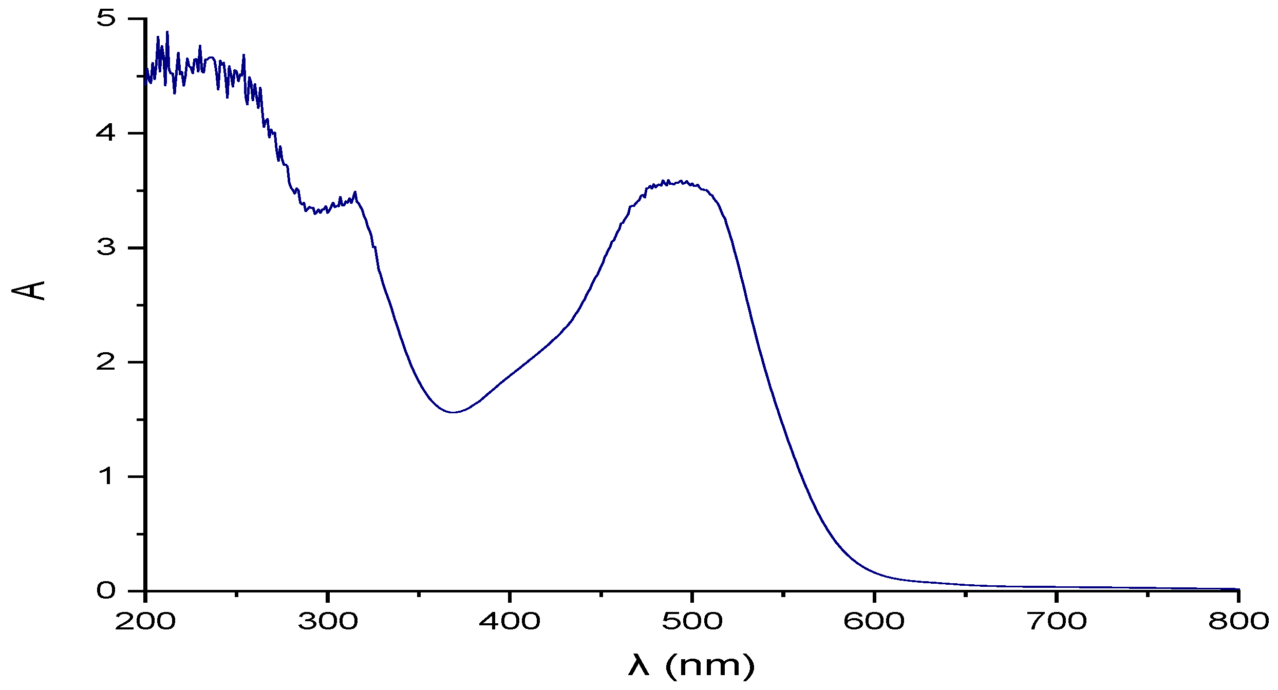
| Parameter | pH | COD (mg/L) | EC (mS/cm) | Cl− (mg/L) | SS (mL/L) | TDS (mg/L) | TS (mg/L) | Red Coloring Absorbance at 490 nm |
|---|---|---|---|---|---|---|---|---|
| Parameter value | 9 ± 0.1 | 4640 ± 100 | 87.5 ± 15 | 36,301 ± 125 | 190 ± 0.5 | 66,100 ± 150 | 66,300 ± 550 | 3.5 |
| Parameters | Industrial Effluent | Treated Industrial Effluent | Requirements of Industry and Potable Water Standard Regulations | |||||
|---|---|---|---|---|---|---|---|---|
| Operation 1 Sedimentation (S) | Operation 2 Adsorption by AC | Operation 3 IEXR | Operation 4 RO Membrane(Permeate) | |||||
| Cationic | Anionic I | Anionic II | ||||||
| pH | 9 ± 0.1 | 8.06 ± 0.05 | 8.5 ± 0.1 | 7.8 ± 0.1 | 8.2 ± 0.2 | 8.5 ± 0.1 | 7.6 ± 0.2 | 6–9 |
| EC (mS/cm) | 87.5 ± 15 | 86.5 ± 0.01 | 82.1 ± 0.02 | 43.8 ± 0.01 | 35.9 ± 0.01 | 18 ± 0.2 | 0.64 ± 0.1 | <1.8 |
| Cl− (mg/L) | 36,301 ± 125 | 36,301 ± 140 | 30,558 ± 140 | 18,184 ± 70 | 8345.5 ± 20 | 3435 ± 15 | 207 ± 70 | <250 |
| COD (mg/L) | 4640 ± 100 | 4530 ± 100 | 56 ± 20 | 98 ± 20 | 71 ± 2 | 24.6 ± 2 | N. D | Undefined |
| TS (mg/L) | 66,300 ± 550 | 66,260 ± 200 | 63,162 ± 200 | 35,685 ± 100 | 16,240 ± 150 | 5100 ± 15 | 128 ± 2 | <1000 |
| TDS (mg/L) | 66,100 ± 150 | 66,000 ± 100 | 62,050 ± 200 | 35,105 ± 100 | 15,985 ± 150 | 5120 ± 15 | 125 ± 2 | <300 |
| SS (mL/L) | 190 ± 0.5 | *ND | ND | ND | ND | ND | ND | <10 |
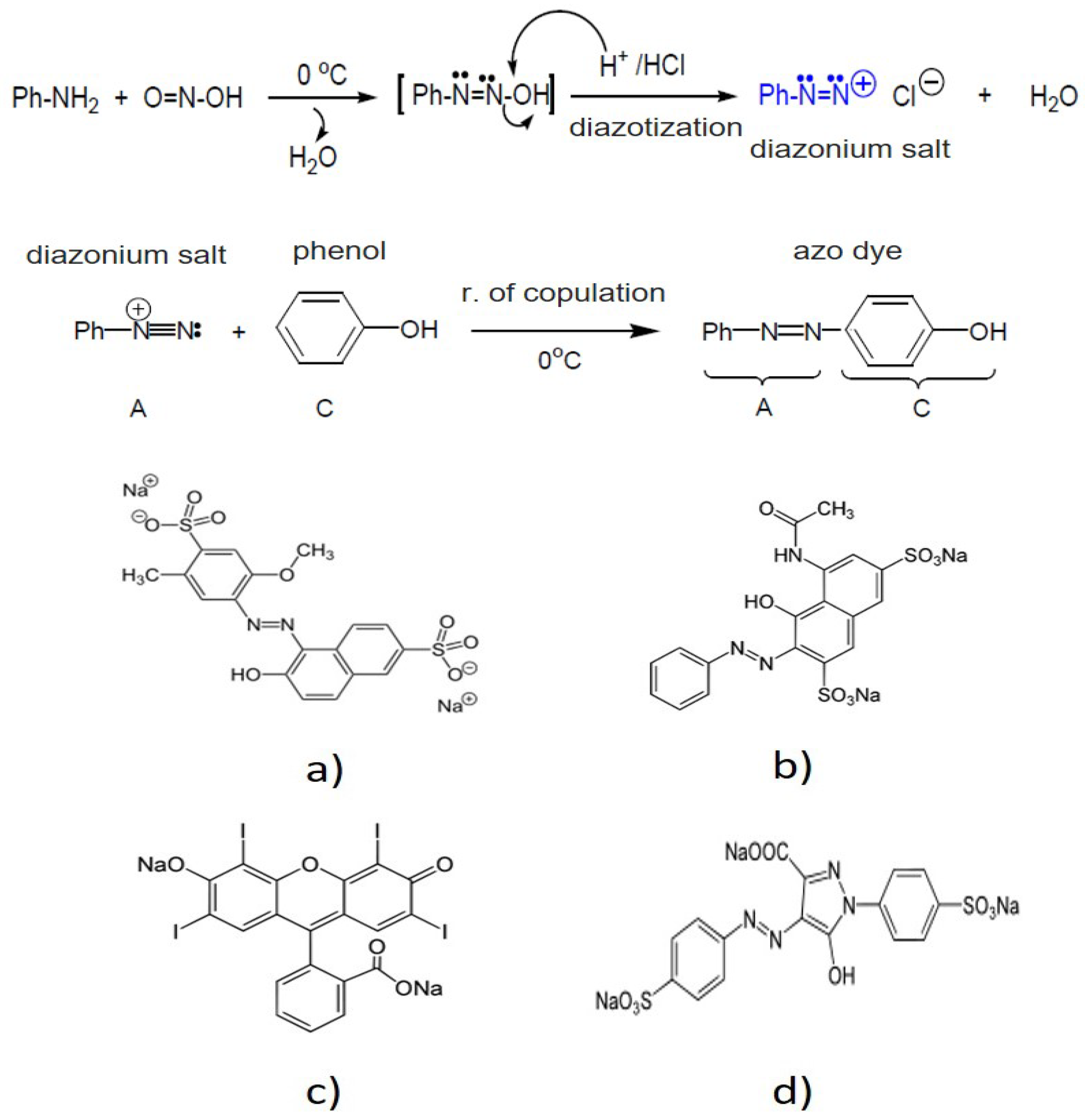
| Red coloring Absorbance | 3.5 10% dilution | 3.5 10% dilution | ND | ND | ND | ND | ND | Uncolored |
| Packaging Materials | AC (COD) | Cationic IEXR (TDS) | Anionic IEXR-I (TDS) | Anionic IEXR-II (TDS) |
|---|---|---|---|---|
| Runs of effluent treatment | 30 | 15 | 15 | 15 |
| Co (mg/L) | 4530 ± 100 | 62,050 ± 200 | 35,105 ± 100 | 15,985 ± 150 |
| Cb (mg/L) | 150 ± 50 | 52,500 ± 100 | 25,907 ± 150 | 7456 ± 120 |
| Vb (L) | 5 ± 0.2 | 2 ± 0.5 | 2 ± 0.5 | 2.5 ± 0.5 |
| θb (h) | 20 ± 3 | 11 ± 2 | 11 ± 2 | 15 ± 2 |
| Q (mL/min) | 4 ± 0.3 | 3 ± 0.3 | 3 ± 02 | 2 ± 0.2 |
| qb1 (mg/mL) | 91 ± 1 | 80 ± 1 | 77 ± 1 | 88 ± 1 |
| qb2 (mg/g) | 3425 ± 100 | 8531 ± 100 | 5408 ± 100 | 2985 ± 100 |
| Parameters | Feed Flow (L/min) | ||
|---|---|---|---|
| 0.5 | 0.7 | 1.0 | |
| SDI | 0.98 ± 0.1 | 0.97 ± 0.1 | 1.1 ± 0.1 |
| Rt | 43 ± 1 | 45 ± 1 | 55 ± 1 |
| Rm | 5 ± 0.1 | 5 ± 0.1 | 5 ± 0.1 |
| Rir | 14 ± 1 | 14 ± 1 | 35 ± 1 |
| Rr | 24 ± 1 | 25 ± 1 | 15 ± 1 |
Publisher’s Note: MDPI stays neutral with regard to jurisdictional claims in published maps and institutional affiliations. |
© 2022 by the authors. Licensee MDPI, Basel, Switzerland. This article is an open access article distributed under the terms and conditions of the Creative Commons Attribution (CC BY) license (https://creativecommons.org/licenses/by/4.0/).
Share and Cite
Hernández, K.; Muro, C.; Monroy, O.; Diaz-Blancas, V.; Alvarado, Y.; Diaz, M.d.C. Membrane Water Treatment for Drinking Water Production from an Industrial Effluent Used in the Manufacturing of Food Additives. Membranes 2022, 12, 742. https://doi.org/10.3390/membranes12080742
Hernández K, Muro C, Monroy O, Diaz-Blancas V, Alvarado Y, Diaz MdC. Membrane Water Treatment for Drinking Water Production from an Industrial Effluent Used in the Manufacturing of Food Additives. Membranes. 2022; 12(8):742. https://doi.org/10.3390/membranes12080742
Chicago/Turabian StyleHernández, Karina, Claudia Muro, Oscar Monroy, Vianney Diaz-Blancas, Yolanda Alvarado, and María del Carmen Diaz. 2022. "Membrane Water Treatment for Drinking Water Production from an Industrial Effluent Used in the Manufacturing of Food Additives" Membranes 12, no. 8: 742. https://doi.org/10.3390/membranes12080742