Abstract
Membrane-based gas separation is a promising unit operation in a low-carbon economy due to its simplicity, ease of operation, reduced energy consumption and portability. A methodology is proposed to immobilise enzymes in stable water-in-oil (W/O) emulsions produced by direct membrane emulsification systems and thereafter impregnated them in the pores of a membrane producing emulsion-based supported liquid membranes. The selected case-study was for biogas (CO2 and CH4) purification. Upon initial CO2 sorption studies, corn oil was chosen as a low-cost and non-toxic bulk phase (oil phase). The emulsions were prepared with Nadir® UP150 P flat-sheet polymeric membranes. The optimised emulsions consisted of 2% Tween 80 (w/w) in corn oil as the continuous phase and 0.5 g.L−1 carbonic anhydrase enzyme with 5% PEG 300 (w/w) in aqueous solution as the dispersed phase. These emulsions were impregnated onto a porous hydrophobic PVDF membrane to prepare a supported liquid membrane for gas separation. Lastly, gas permeability studies indicated that the permeability of CO2 increased by ~15% and that of CH4 decreased by ~60% when compared to the membrane without carbonic anhydrase. Thus, a proof-of-concept for enhancement of CO2 capture using emulsion-based supported liquid membrane was established.
1. Introduction
Global warming, the direst threat to the planet, has been a highly debated topic all over the world. Carbon dioxide (CO2) is considered to be the major contributor to global warming mainly due to its increased production during the combustion of fuels for the generation of power [1]. To avoid the catastrophic climatic changes brought about by the emission of CO2 into the atmosphere, research in the field of carbon capture and storage has been progressing rapidly. Another application of CO2 capture is encountered in the purification of biogas, a carbon neutral alternative renewable energy resource [2]. Biogas is mainly constituted by CH4 and CO2 along with several contaminants such as ammonia (NH3), carbon monoxide (CO), water vapour, methyl siloxanes, hydrogen sulfide (H2S), nitrogen (N2), oxygen (O2), halogenated volatile organic compounds (VOCs) and hydrocarbons. It is crucial to purify biogas by removing the contaminants (mainly CO2 and H2S) in order to increase the calorific value and upgrade it to be used as a cleaner fuel [3].
Pre-combustion, oxyfuel combustion and post-combustion are the three major technologies adapted for CO2 capture and storage and CO2 conversion and utilisation. Post-combustion carbon capture technologies are the most common techniques used for CO2 capture. These include absorption, adsorption, membrane-based separation and enzyme-based methods [4,5]. Amine-based carbon capture (e.g., with functional amines such as monoethanolamine-MEA, N-methyldiethanolamine-MDEA) [6] is the most widely used technique of absorption [4,7]. Membrane-based separation includes the utilisation of membrane contactors, high temperature and permselective polymers and blend membrane materials, whereas enzyme-based methods involve enzyme catalytic hydrolysis and carbonic anhydrase [4,8,9,10].
When using enzymatic systems, the success of CO2 capture and storage and CO2 conversion are highly dependent on the ability to convert (transfer) CO2 to an aqueous phase from the gas stream. Carbonic anhydrase, which has a hydroxide-bound Zn2+ in its active site, catalyses the inter-conversion between carbon dioxide and bicarbonate promoting the above mentioned requirement [11]. Carbonic anhydrase has been known to promote CO2 absorption and desorption, leading to an improvement in the reaction kinetics and further reduction in the cost of energy required to release the absorbed CO2 in solvent-based CO2 capture [12]. Though the utilisation of carbonic anhydrase has its benefits, factors such as the presence of impurities, high salt concentration during absorption and the poor stability of the enzyme at alkaline pH and high temperature, restricts its use at an industrial level for CO2 capture. Hence, the study of processes using carbonic anhydrase for CO2 capture is still a highly researched topic [11].
Membranes are permselective barriers between two phases [13,14]. Liquid membranes (LMs), as the name suggests, are membranes usually comprising at least one liquid component in it [15]. The advancement in liquid membrane technology is credited to Li et al., who patented emulsion liquid membranes (ELMs) for applications in hydrocarbon separation and desalination at an industrial scale in the year 1968 [16,17]. Bulk liquid membranes (BLMs), supported liquid membranes (SLMs) and emulsion liquid membranes are the three main categories of liquid membranes [15]. Among these, ELMs are currently used extensively in extraction and separation-based applications [15]. Basically, ELMs are systems in the form of double emulsions (water-in-oil emulsion dispersed in an external aqueous phase or oil-in-water emulsion dispersed in an outer organic phase) [18]. However, the physical instability of the ELMs and the de-emulsification processes required is still a major disadvantage from practical industrial perspective [18]. Additionally, formation of double emulsions in comparison to simple emulsions involves 2 cycles of emulsification, which makes it an energy-intensive process. The combination of the principles of SLMs with tailor-made emulsions as a functional solvent sets the premise of the present study.
Emulsions have been formed by both high-energy methods and low-energy methods. While high-energy methods include those methods which use mechanical devices that are highly energy intensive, such as ultrasonicators, microfluidisers and high-pressure homogenisers, low-energy methods are those which form emulsions as a result of structural changes and processing conditions at the interfaces, such as by spontaneous emulsification, bubble bursting and phase inversion temperature methods [19]. Among the high-energy methods, ultrasound-assisted emulsification is preferred, as it comparatively consumes lower energy with a reduced risk of contamination by the experimental unit [20]. However, a technique that has garnered interest in recent years in the field of emulsification is membrane emulsification, a low-energy method performed at low shear stress and mild operating conditions [19]. This technique seems to be more effective in terms of productivity and energy consumption for producing emulsions with smaller sizes and controlled dispersity. Detailed comparison of membrane emulsification with traditional methods such as mechanical stirrers, homogenisers and ultrasonicators has been recently reported [19,21,22,23,24].
Liquid membranes have been used in the past for applications such as acid recovery and dye removal from aqueous solutions and extraction of metals [25,26,27,28,29]. Furthermore, the emulsions in these studies were produced by techniques involving homogenisers, high-speed mixers and ultrasonicators. The present study is an attempt to produce emulsions using the more effective membrane emulsification technique and using them to prepare emulsion-based supported liquid membranes. Additionally, this research work also explores these membranes for gas-based applications by evaluating their gas transport properties. In the present study, various commercial oils with potential CO2 capture ability were initially screened to be used as the continuous phase for the formation of water-in-oil emulsions by membrane emulsification. Prior to these emulsification experiments, the continuous phase, the chosen dispersed phase and the polymeric membrane to be used were characterised in terms of interfacial tension between two phases and the static contact angle of the continuous phase on the membrane surface. To evaluate the effect of carbonic anhydrase on the CO2 capture ability of the system, emulsions were produced both without and with the functional enzyme. Furthermore, supported liquid membranes (SLMs) were prepared by impregnation of oil onto a porous membrane support, and emulsion-based supported liquid membranes were formed by impregnation of the produced emulsion onto a porous membrane support. Finally, gas permeability measurements of CO2 and CH4 across the synthesised SLMs were performed.
2. Materials and Methods
2.1. Materials
The commercial oils screened were olive oil (Gallo, Alges, Portugal), sunflower oil (Fula, Alges, Portugal) and corn oil (Fula, Alges, Portugal). Surfactants used for emulsification were PEG 300 (Clariant, Muttenz, Switzerland), Span® 80, Tween® 80, Triton™ X-100 Detergent and SDS (≥99% (GC), dust-free pellets), which were procured from Sigma Aldrich, Portugal (made in Lyon, France). Potassium carbonate (>99.5% pure, Scharlab S.L., Sentmenat, Spain) was used to prepare a solution to adjust the pH to 11. Carbonic anhydrase from bovine erythrocytes (≥95% (SDS-PAGE), specific activity ≥3500 W-A units/mg protein, lyophilised powder) was acquired from Sigma Aldrich, Portugal (made in St. Louis, MI, USA). The gases used, carbon dioxide (98% purity) and methane (99% purity) were purchased from Praxair (Huelva, Spain). The commercial membranes used in this study are detailed in Table 1.

Table 1.
Details of commercial membranes used in this study.
2.2. Schematic Representation of Experimental Workplan
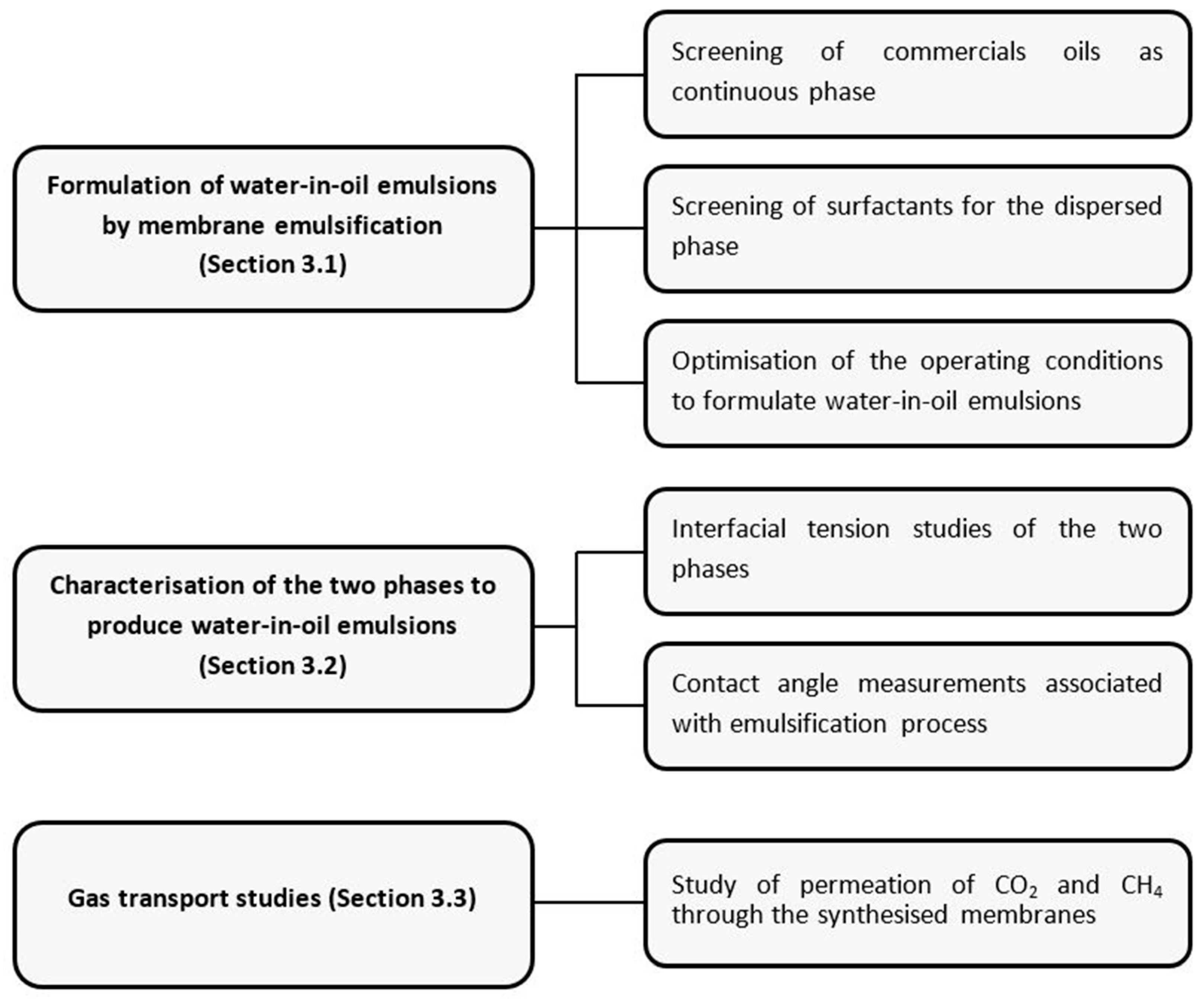
A scheme representing the series of experiments performed in order to obtain a functionalised membrane with favourable gas transport properties is detailed in Figure 1.

Figure 1.
Schematic representation of experimental study.
2.3. Optimisation of the Two Phases to Produce Water-in-Oil Emulsions
2.3.1. Screening of Commercials Oils as Continuous Phase
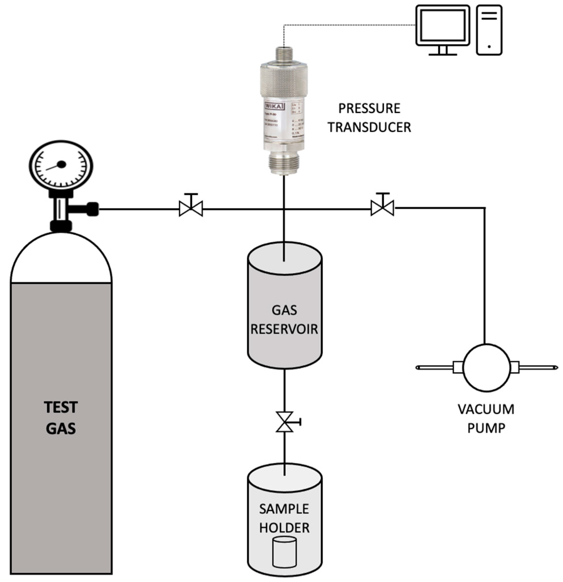
Commercial oils such as olive oil, sunflower oil and corn oil were initially screened to be used as the continuous phase of the emulsion. These oils were preferred since they meet the requirement for a cheap, sustainable and functional bulk carrier. Additionally, since the aim of this study was to obtain a supported liquid membrane with high permeability and selectivity for CO2 capture, it was essential to choose a continuous phase containing a bulk carrier having a high affinity towards CO2. Thus, to check the CO2 uptake capacity, sorption studies with the above-mentioned commercial oils were carried out using a dual-volume sorption unit as illustrated in Figure 2. The set-up consisted of a sample holder and a storage vessel (gas reservoir). A pressure transducer connected to the gas reservoir measured the pressure in the storage vessel in real-time.
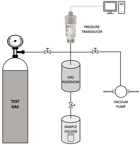
Figure 2.
Schematic representation of the sorption unit used in the study.
For the evaluation of sorption capacity, the sample holder (containing the sample) was initially set under vacuum conditions for about 24 h to release any gases trapped within. Subsequently, the valve to the sample holder was closed and carbon dioxide gas was supplied into the storage reservoir up to a pressure of 160.1 kPa. Once the pressure was stabilised, the valve to the sample holder was opened and the subsequent pressure decay was recorded. The amount of gas sorbed and the resulting sorption coefficient was evaluated by the Equations (1) and (2), respectively.
In the Equation (1), ‘ni,sample’ [mol] is the number of moles of gas ‘i’ sorbed onto a given sample. ‘Po’ [atm] and ‘Pt’ [atm] are the initial pressure of gas in the storage vessel and the pressure at time ‘t’ [s] after the gas is introduced into the sample holder, respectively. ‘VR’ [m3] and ‘VS’ [m3] are the volumes of the storage vessel and the sample holder, respectively. ‘R’ [cm3atm·K−1mol−1] refers to the universal gas constant and ‘T’ [K] the absolute temperature at which the experiment was performed.
The sorption coefficient ‘Si’ [m3 (STP)m3sampleatm−1] was evaluated as follows:
where, ‘Vi,sample‘ [m3] is the volume of gas ‘i’ corresponding to ‘ni,sample’ at STP conditions (1 atm, 273.15 K). ‘Pstabilised’ [atm] is the pressure stabilised within the dual-volume sorption unit at equilibrium conditions.
Furthermore, for the formation of emulsions, surfactants of different hydrophilic and lipophilic balance (HLB) were tested as a component with the selected commercial oil to constitute the continuous phase. Specifically, Tween 80, Span 80 and an equimolar mixture of them were tested for emulsification. 2% (w/w) was optimised as the concentration of Tween 80 in the continuous phase (data not shown).
2.3.2. Selection of Dispersed Phase
The dispersed phase consisted of ultrapure MilliQ® IQ water along with the carbonic anhydrase enzyme as the functional compound. Carbonic anhydrase has been reported to have high enzymatic activity at ~pH 10–11 [30]. Therefore, the pH of the dispersed phase was accordingly adjusted using potassium carbonate salt. The concentration of carbonic anhydrase used was previously optimised as 0.5 gL−1. Moreover, several surfactants, namely SDS, Tween 80, Triton X-100 and PEG 300, were tested to stabilise the carbonic anhydrase and facilitate the emulsion formation. The influence of the surfactants on the carbonic anhydrase was studied using fluorescence-anisotropy technique as described by Castro et al. [30] Fluorescence emission measurements were recorded using a Spex Fluorolog 3 spectrofluorometer (Horiba, Kyoto, Japan) with an excitation wavelength (λex) of 295 nm and emission wavelength (λem) from 300–550 nm with excitation and emission slits of 5 nm. Datamax software was used to acquire the data.
2.3.3. Characterisation of the Optimised Phases and the Membrane Used for Emulsification Studies
Interfacial Tension Studies
A reduced interfacial tension between the dispersed phase and the continuous phase used in a membrane emulsification study promotes the formation of emulsions [24]. Hence, the interfacial tension between the two phases was determined using a Drop Shape Analyzer (DSA 25B, Kruss GmbH, Hamburg, Germany). The fit of the pendant drop profile obtained from the software and the Laplace–Young equation was used to calculate the interfacial tension values. The measurements were carried out in triplicate at room temperature (21 ± 1 °C) and the resulting average values were considered.
Contact Angle Studies
During membrane emulsification studies, the dispersed phase should not wet the active layer of the membrane (where the droplet detachment occurs) to avoid coalescence on the membrane surface. Furthermore, it is imperative that the continuous phase wets the membrane surface to facilitate the detachment of the emulsions from the surface [23]. The measurement of the static contact angle of the membrane under study with the liquid phases employed further ensures the suitability of the membrane for the emulsification process. Therefore, the abovementioned Drop Shape Analyzer was used to perform the required static contact angle measurements by sessile drop method.
2.4. Formulation of Water-in-Oil Emulsions by Membrane Emulsification
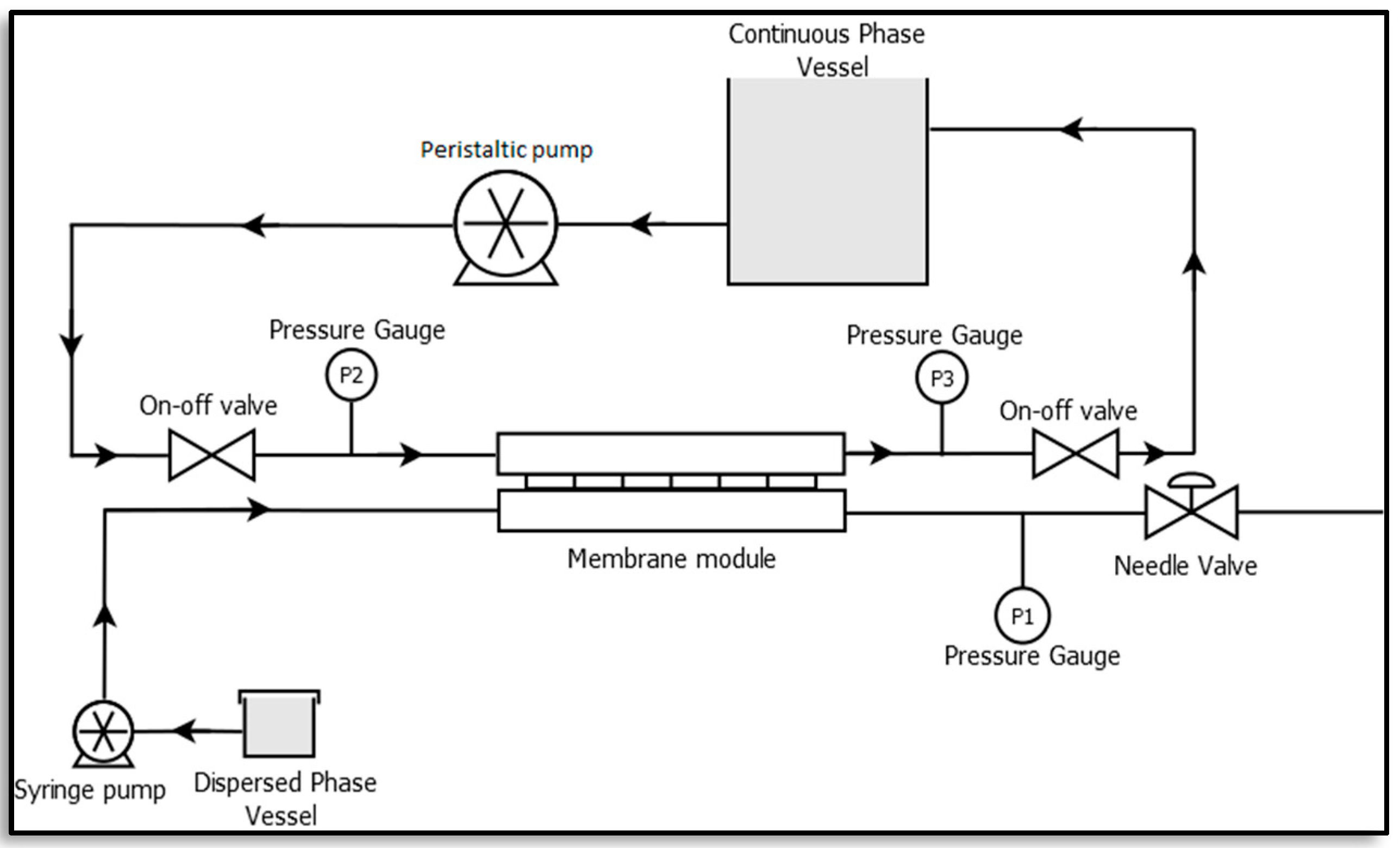
A membrane emulsification unit was set-up at the lab scale as illustrated in Figure 3 [23,24]. It consists of a rectangular membrane module made of stainless steel which lodges a membrane of active area 2.9 × 10⁻⁴ m2, a syringe pump (Harvard Apparatus, PHD ULTRA 4400 I/W PROG, Cambridge, MA, USA) and a peristaltic pump (Velp Scientific, SP311, Usmate Velate, Italy). A constant volume of dispersed phase, resulting in a defined flux, was injected through the membrane into the continuous phase by the syringe pump, while the peristaltic pump was used to recirculate the continuous phase.
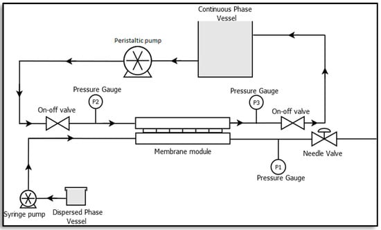
Figure 3.
Membrane emulsification set-up [23].
The automated syringe pump was used to set the dispersed phase flow rate, ‘QDP’ [m3.s−1] while the continuous phase cross flow velocity, ‘νc’ [m.s−1] was calculated as follows [23,24]:
where ‘QCP’ [m3.s−1] is the flow rate of the continuous phase and ‘Dh’ [m] is the hydraulic diameter of the flow channel.
Next, 1%, 2% and 5% of dispersed phase to continuous phase volume ratios were tested for the formation of emulsions. For the emulsification process, the dispersed phase was forced through the membrane using the syringe pump while the continuous phase was recirculated using a peristaltic pump in the system. The dispersed phase passes through the membrane pores because of the applied transmembrane pressure and disperses into the continuous phase to form water-in-oil emulsions. For the optimised emulsification process, the transmembrane pressure went up to ~149.9 kPa. The emulsions formed were further characterised using an optical microscope (H550S, Nikon, Japan).
2.5. Preparation of Supported Liquid Membranes
The liquid membranes were prepared by filling the pores of a hydrophobic PVDF Durapore® membrane filter (MilliporeSigma, Burlington, MA, USA) of nominal pore size 0.22 µm with the emulsion solutions previously formed. This procedure was accomplished in a dead-end stainless steel METCell set-up as depicted in Figure 4 (Membrane Extraction Technology, London, UK). The experiments were performed at a constant controlled pressure of 395.2 kPa with a porous, stainless steel disc supporting the membrane filter. At first, the feed solution was poured over the membrane into the METcell unit. Then it was pressurised through the membrane pores by an inert gas (Argon) until 90% of the feed solution was collected in the permeate chamber. The excess solution was gently removed with a tissue paper and the membranes were subsequently air-dried in a desiccator. The membrane was weighed before and after this procedure to determine the amount of feed emulsion solution that has been incorporated into the membrane pores.
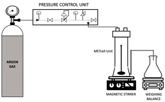
Figure 4.
Schematic representation of the set-up for preparation of supported liquid membranes.
2.6. Gas Transport Studies
The single gas permeability of CO2 and CH4 through the prepared membranes was measured using a gas permeation unit as described elsewhere [31]. The membrane permeation cell consists of two identical compartments, made of stainless steel, separated by the membrane to be tested as illustrated in Figure 5. The permeation cell was kept in a thermostatic water bath to maintain a constant temperature during the experiment. Initially, the gas under study (CO2 or CH4) was introduced into both the compartments until the pressure was stabilised. Subsequently, the required transmembrane pressure was established. Pressure transducers were used to measure the variation in pressure with time in both the compartments. An in-house developed software was used to monitor the pressure and acquire the data.
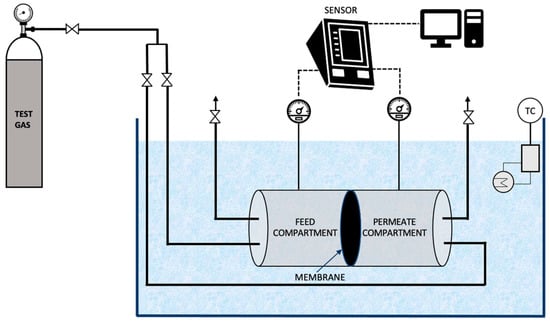
Figure 5.
Schematic representation of the gas permeation unit used in the study.
The permeability of a gas through the membrane was calculated [31] by Equation (4)
where the pressures in the feed compartment and permeate compartment are ‘Pfeed’ [bar] and ‘Pperm’ [bar], respectively. ‘Lp’ [m2s−1] is the permeability of a membrane of thickness ‘l’ [m] and ‘t’ [s] is the time. ‘β’ [m−1] is the characteristic of the geometry of the cell calculated by the Equation (5) where, ‘A’ [m2] is the membrane area and ‘Vfeed’ and ‘Vperm’ are the volumes of the feed compartment and permeate compartment, respectively.
The permeability of the gas was calculated from the slope obtained by plotting versus . Subsequently, the ideal selectivity, ‘α’, was calculated by dividing the permeability of the more permeable gas with the permeability of the less permeable gas.
3. Results and Discussion
3.1. Formulation of Water-in-Oil Emulsions by Membrane Emulsification
3.1.1. Sorption Studies for Screening of Commercials Oils as Continuous Phase
Regular food-grade oils were chosen as the oil phase for the bulk of the emulsions. The sorption results obtained at 30 °C are reported in Table 2. The various oils presented similar sorption coefficients for CO2. Considering the cost, either sunflower oil or corn oil could have been chosen as the continuous phase. However, since the CO2 sorption of corn oil was slightly higher, it was chosen as the continuous phase.
Table 2.
Sorption coefficients of oils at 30 °C.
3.1.2. Screening of Surfactants for Dispersed Phase
A fluorescence analysis of the enzyme in the presence of different surfactants was performed (as shown in the Figure 6). The results suggest that PEG 300 was the surfactant that best preserved the conformation of the enzyme, since only slight band shifts were observed (curve almost overlapped with the control sample). On the other hand, Tween and SDS caused drastic changes in the conformation of the enzyme, from the point of view of exposure of the aromatic residues of tryptophan to the solvent. Additionally, the concentration of PEG 300 to be used was optimised as 5% (v/v). Therefore, this condition was selected for the next phase of the study.
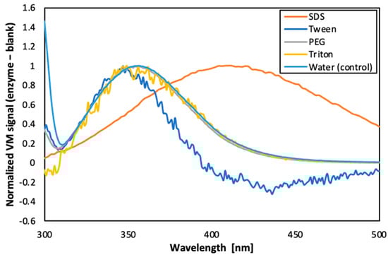
Figure 6.
Fluorescence emission spectra of carbonic anhydrase in presence of different surfactants.
Furthermore, as reported in literature, PEG is known to stabilise enzymes by forming hydrogen bonds, which could displace water and prevent protein aggregation [32]. Furthermore, PEG has also been reported to reduce the viscosity ratio between the dispersed and the continuous phase (by enhancing the dispersed phase viscosity) which contributes to shrinkage of the emulsion droplets [33,34].
3.1.3. Optimisation of the Operating Conditions to Formulate Water-in-Oil Emulsions
Membrane emulsification was performed to formulate water-in-oil emulsions both without and with the functional agent (the carbonic anhydrase enzyme) using the methodology detailed in Section 2.4. Various emulsions were prepared (both without and with carbonic anhydrase) with volumetric ratio of dispersed phase to continuous phase ranging from 1%, to 2% and 5%. The dispersed phase flux was also varied (10.80 L.h−1.m−2 and 1.01 L.h−1.m−2) in order to understand its impact. The continuous phase cross flow velocity was kept constant at 0.15 m.s−1, which corresponds to wall shear stress of 11.9 Pa. Moreover, 2% (w/w) of Tween 80 was optimised as the best surfactant concentration in the continuous phase as the other surfactants and concentrations tested were either not able to emulsify completely, or the resultant emulsions had excess of surfactant. The different emulsions obtained were further characterised by optical microscopy (refer Figure 7).

Figure 7.
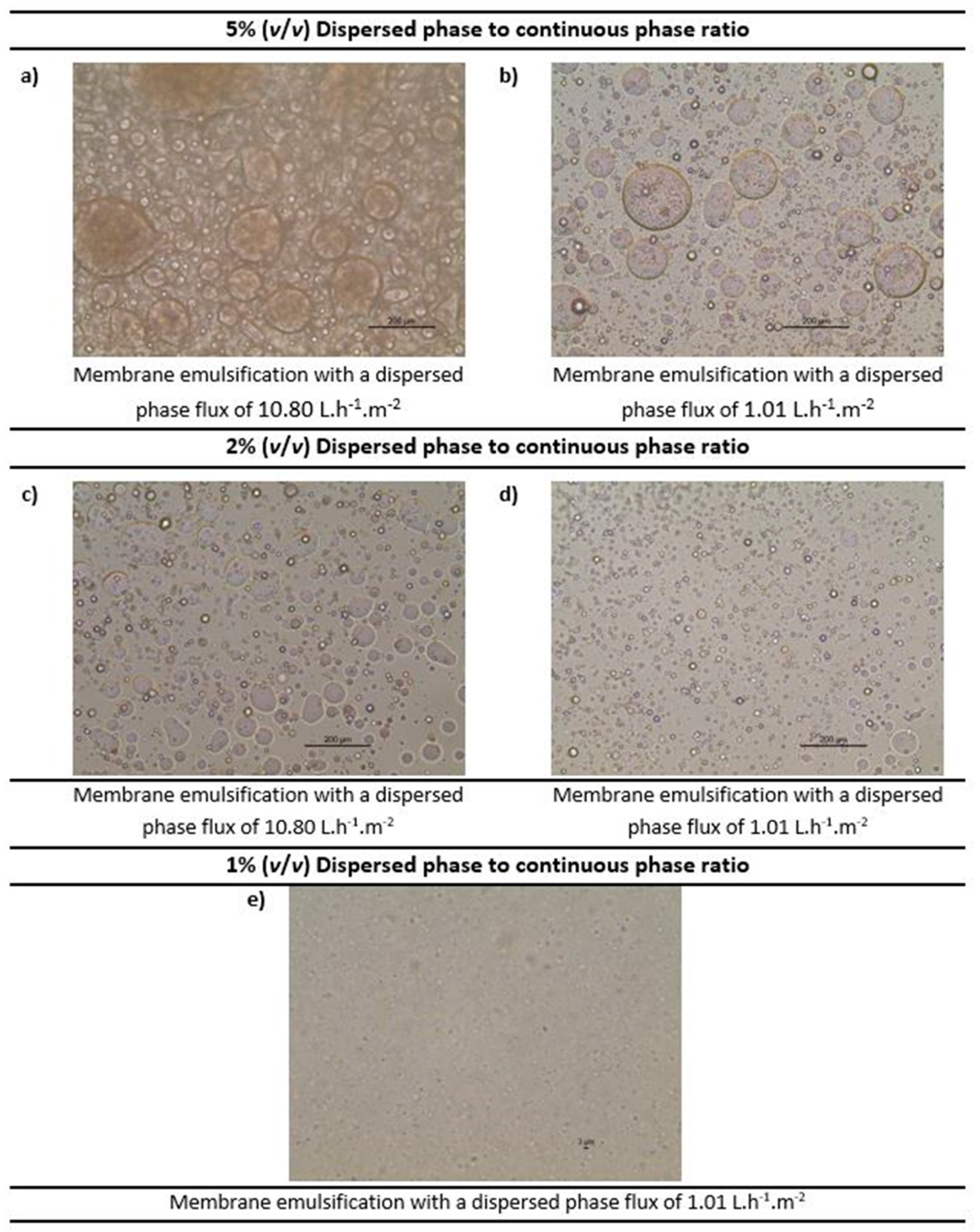
Optimisation of the water-in-oil emulsions (at constant crossflow velocity of the continuous phase) by optical microscopy. Note: The scale shown in the images 6 (a–d) is 200 µm and in 6 (e) is 3 µm.
As observed in Figure 7, as we reduce the volume ratio, the emulsion droplets become smaller. For 5% concentration (Figure 7a,b) and 2% concentration (Figure 7c,d), the droplets are in the micro-meter range, while for the 1% concentration (Figure 7e) the droplets are so small that they are barely visible. Moreover, it was observed that the lower dispersed phase flux (based on the dispersed phase flowrate) promotes the production of more uniform emulsions (see Figure 7d). These results were consistent with the literature [23,35]. Hence, emulsions formed by a 1% volume ratio of dispersed phase to continuous phase and dispersed phase flux of 1.01 L.h−1.m−2 were selected for further investigation.
Based on visual observation, a stable emulsion was formed. However, as the bulk of the emulsions formulated in this study were made using corn oil (an oil with yellowish colour), inconclusive results were obtained when characterised by DLS.
3.2. Synthesis and Characterisation of Water-in-Oil Emulsions by Membrane Emulsification
3.2.1. Interfacial Tension Studies of the Two Phases
The interfacial tension of the dispersed phase and of the continuous phase, measured by the pendant drop method, are shown in Figure 8. According to the literature, the interfacial tension of conventional hydrophobic oils with water are in the range of 22–26 mN.m−1 [36]. In the present study, the interfacial tension of corn oil with water was determined to be 23.69 ± 0.04 mN.m−1, which is on par with literature. On the addition of surfactant (2% (w/w) Tween 80) to the corn oil (the continuous phase), the interfacial tension reduced significantly, showing an interfacial tension value of 0.58 ± 0.01 mN.m−1. The reduction of the interfacial tension by emulsifiers can be attributed to the quick adsorption of the emulsifier onto the interface of immiscible liquids to promote their interaction [19,20]. There was a further reduction in the interfacial tension value to 0.11 ± 0.01 mN.m−1 between the dispersed phase and the continuous phase where the dispersed phase consisted of water and 5% PEG 300. This drastic reduction in the interfacial tension in presence of Tween 80 surfactant to values close to zero facilitates the formation of droplets of the dispersed phase in the continuous phase.
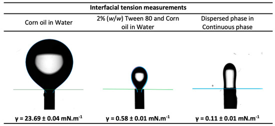
Figure 8.
Interfacial tension measurements of the continuous phase and dispersed phase.
3.2.2. Contact Angle Measurements Associated with the Emulsification Process
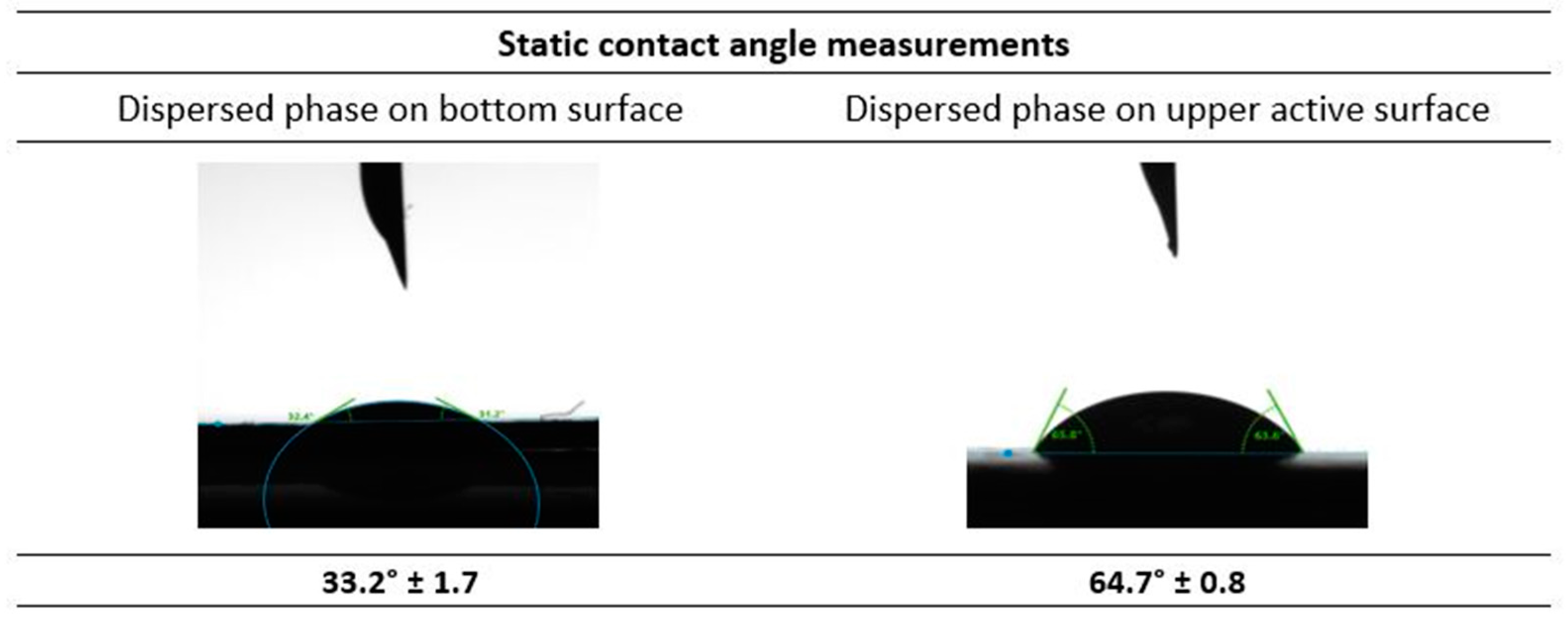
The contact angle of the top (active) and bottom surfaces of the UP150, Polyethersulfone (PES) membrane were measured with respect to the dispersed phase (Water + 5% PEG 300 + Carbonic anhydrase). The results depicted in Figure 9 show that the contact angle of the dispersed phase with the bottom surface of the membrane is 33.2° ± 1.7. This implies that the dispersed phase easily wets the surface, contributing to lower the pressure required for the membrane emulsification process. Furthermore, the contact angle for the dispersed phase with the opposite active upper side of the membrane was found to be 64.7° ± 0.8. This value shows that the upper side of the membrane is relatively more hydrophobic than the bottom side, which facilitates the detachment of the emulsion droplets formed, to the continuous phase. So, in the presence of a cross-flow shear from the continuous phase, the formation of emulsion droplets is favoured. This is in favour of the formation of emulsions, as reported previously in [35]. As the dispersed phase passes through the membrane pores, the continuous phase is able to detach from the membrane surface to form emulsions.
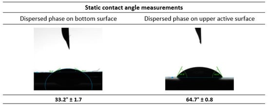
Figure 9.
Static contact angle measurements of the dispersed phase with the membrane selected for the membrane emulsification studies.
3.3. Gas Transport Studies of CO2 and CH4 through the Synthesised Membranes
The effect of the inclusion of carbonic anhydrase in the emulsion was studied by measuring the pure gas permeability of CO2 and CH4. The single gas permeabilities were measured with a 69.9 kPa transmembrane pressure at 30 °C. The ideal gas permeability was calculated as a ratio of the two permeabilities. Firstly, the permeabilities of the SLM, formed by the hydrophobic PVDF support and corn oil, were tested and then compared with the permeabilities of the SLMs formed by introduction of the emulsions within the porous structure of a similar membrane support. It was observed that for the SLM and the emulsion based SLM without carbonic anhydrase, the permeabilities were almost similar (see Table 3). This was expected as the emulsion-based SLM without carbonic anhydrase has no components to facilitate the transport of CO2. On the contrary, upon inclusion of carbonic anhydrase in the emulsions, there was a drastic improvement in the CO2/CH4 selectivity. This can be attributed to the facilitated transport of CO2 by the carbonic anhydrase. It was noted that along with the facilitated CO2 transport, CH4 transport was further reduced, which led to a higher selectivity of emulsion-based SLMs in comparison to SLMs. We know that CH4 is a non-polar molecule. Hence, upon the introduction of water (polar solvent) as dispersed phase, the permeability of CH4 slightly decreased. Moreover, London dispersion forces (dominant in nonpolar molecules) are much weaker than dipole–dipole interactions (dominant in polar solvents). Therefore, the propensity of non-polar molecules to interact with polar solvents is minimum. This is because of the energy released due to formation of dispersion forces between such molecules is not enough to break strong dipole–dipole interactions between polar molecules. Hence, CH4 transport is further inhibited in presence of water in the emulsion droplet. For the emulsions with carbonic anhydrase, the dispersed phase is set at a pH of 11 (for better enzymatic activity). This basic pH further reduces the CH4 solubility and hence its transport, as reported in the literature [37].
Table 3.
Permeabilities of CO2 and CH4 and the selectivity of different membranes.
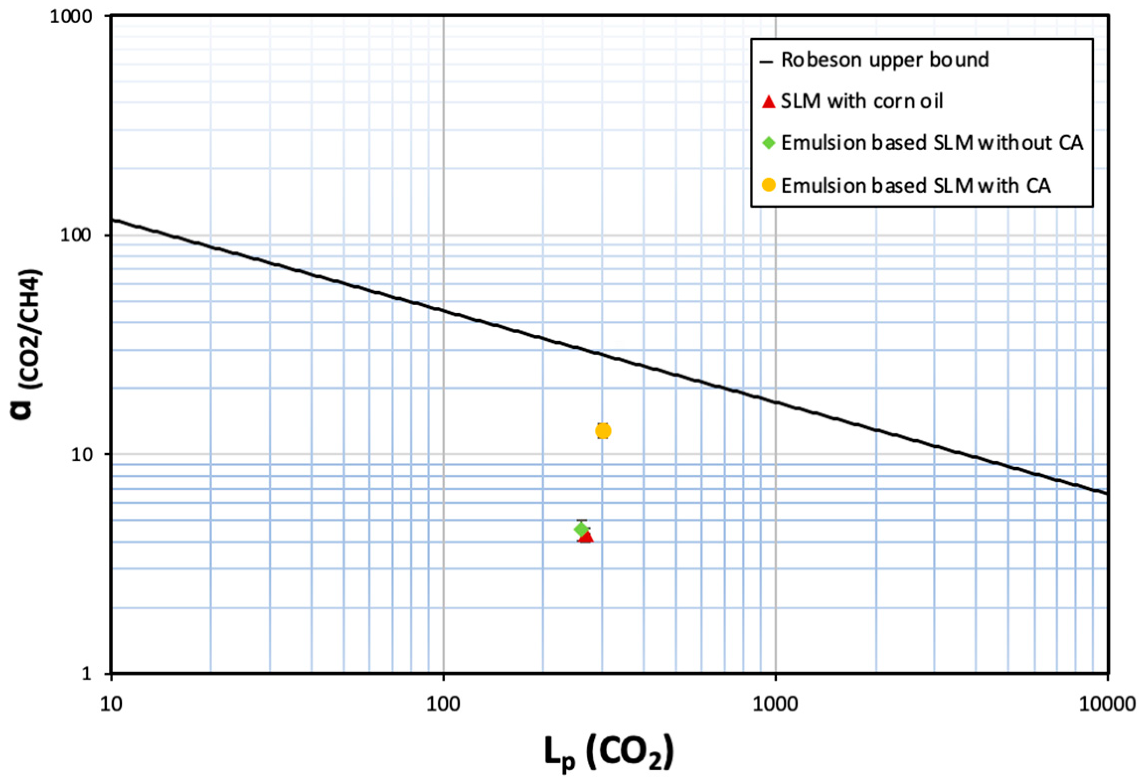
It is interesting to note that even such a small amount of carbonic anhydrase (<4 ppm in the emulsion retained by the supported liquid membrane) can enhance the selectivity by ~3×. The novelty and relevance of this work lies in establishing a proof of concept that demonstrates how the incorporation of carbonic anhydrase in an emulsion immobilised in a porous membrane substrate enhances the selective recovery of CO2 from CH4. When the CO2/CH4 selectivity of these membranes is plotted as a function of CO2 permeability, the membranes are not above the Robeson upper bound plot [38]. Still, there is a clear indication that incorporation of carbonic anhydrase in nano/micro droplets clearly improves the performance of the membrane for biogas separation (see Figure 10).
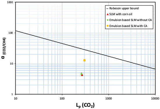
Figure 10.
Comparative analysis of SLMs with conventional Robeson upper-bound plot.
4. Conclusions
A detailed experimental methodology was developed in this study to explore the CO2/CH4 separation capabilities of a bio-based emulsion system impregnated onto a support (porous membrane). Carbonic anhydrase was chosen as the active functional agent to enhance the CO2 transport property of the membrane. An energy efficient and mild direct membrane emulsification technique was effective in formulating the enzyme-based emulsions. Corn oil with 2% (w/w) Tween 80 was used as the continuous phase of the emulsion. The dispersed phase was 0.5 g.L−1 carbonic anhydrase enzyme with 5% PEG 300 (w/w) in aqueous potassium carbonate solution. Nadir® UP150 P flat-sheet polymeric membranes (Microdyn-Nadir GmbH, Wiesbaden, Germany) were used to produce emulsions.
The resulting emulsions were subsequently impregnated onto a microporous hydrophobic PVDF membrane (nominal pore size 0.22 µm) to prepare emulsion-based supported liquid membranes. For comparative studies, the supported liquid membrane (SLM) was prepared by impregnating corn oil onto the membrane and emulsion-based supported liquid membranes were also prepared both without and with the carbonic anhydrase enzyme. It was observed that the permeability of CO2 increased by ~15% and that of CH4 decreased by ~60% through the emulsion-based SLM containing carbonic anhydrase when compared to the SLM and emulsion-based SLM without carbonic anhydrase. Subsequently, the selectivity of CO2 increased in the presence of carbonic anhydrase. It must be stressed that the current study aims to establish a new proof-of-concept through the development of a supported liquid membrane with immobilised emulsions, loaded with a low concentration of functional agent (carbonic anhydrase, in this case). Moreover, it can be safely presumed that loading higher concentration of carbonic anhydrase in the emulsion droplets might contribute in further facilitated transport of CO2, thereby taking the performance of the membranes further close or beyond the Robeson upper bound plot. Furthermore, only the ideal selectivity of gases was evaluated in this work. However, it will be relevant to test the mixed gas selectivity. This sets the premise for further investigation on exploiting such emulsion-based supported liquid membranes.
Author Contributions
Conceptualization, A.M.d.C., U.T.S. and C.B.; methodology, S.M., A.M.d.C. and U.T.S.; software, P.O.-A.; validation, S.M. and B.A.; formal analysis, A.M.d.C. and U.T.S.; investigation, S.M. and A.M.d.C.; resources, J.G.C. and C.B.; data curation, S.M., B.A. and P.O.-A.; writing—original draft preparation, S.M. and B.A.; writing—review and editing, A.M.d.C., U.T.S., J.G.C. and C.B.; visualization, S.M.; supervision, J.G.C. and C.B.; project administration, J.G.C. and C.B.; funding acquisition, C.B. All authors have read and agreed to the published version of the manuscript.
Funding
This research was funded by Fundação para a Ciência e Tecnologia, grant numbers SFRH/BD/146967/2019, SFRH/BD/139389/2018 and PTDC/EQU-EQU/30763/2017-Lisboa-01-0145-FEDER-030763.
Institutional Review Board Statement
Not applicable.
Informed Consent Statement
Not applicable.
Data Availability Statement
The data presented in this study are available on request from the corresponding author.
Acknowledgments
The Associate Laboratory for Green Chemistry—LAQV which is financed by national funds from FCT/MCTES (UIDB/50006/2020).
Conflicts of Interest
The authors declare no conflict of interest. The funders had no role in the design of the study; in the collection, analyses, or interpretation of data; in the writing of the manuscript; or in the decision to publish the results.
References
- Garba, M.D.; Usman, M.; Khan, S.; Shehzad, F.; Galadima, A.; Ehsan, M.F.; Ghanem, A.S.; Humayun, M. CO2 towards fuels: A review of catalytic conversion of carbon dioxide to hydrocarbons. J. Environ. Chem. Eng. 2021, 9, 104756. [Google Scholar] [CrossRef]
- Awe, O.W.; Zhao, Y.; Nzihou, A.; Minh, D.P.; Lyczko, N. A review of biogas utilisation, purification and upgrading technologies. Waste Biomass Valoriz. 2017, 8, 267–283. [Google Scholar] [CrossRef]
- Sun, Q.; Li, H.; Yan, J.; Liu, L.; Yu, Z.; Yu, X. Selection of appropriate biogas upgrading technology-a review of biogas cleaning, upgrading and utilisation. Renew. Sustain. Energy Rev. 2015, 51, 521–532. [Google Scholar] [CrossRef]
- Osman, A.I.; Hefny, M.; Abdel Maksoud, M.I.A.; Elgarahy, A.M.; Rooney, D.W. Recent advances in carbon capture storage and utilisation technologies: A review. Environ. Chem. Lett. 2021, 19, 797–849. [Google Scholar] [CrossRef]
- Embaye, A.S.; Martínez-Izquierdo, L.; Malankowska, M.; Téllez, C.; Coronas, J. Poly (ether-block-amide) copolymer membranes in CO2 separation applications. Energy Fuels 2021, 35, 17085–17102. [Google Scholar] [CrossRef]
- Gladis, A.; Lomholdt, N.F.; Fosbol, P.L.; Woodley, J.M.; von Solms, N. Pilot scale absorption experiments with carbonic anhydrase-enhanced MDEA—Benchmarking with 30 wt% MEA. Int. J. Greenh. Gas Control 2019, 82, 69–85. [Google Scholar] [CrossRef]
- Yamada, H. Amine-based capture of CO2 for utilization and storage. Polym. J. 2021, 53, 93–102. [Google Scholar] [CrossRef]
- Santoro, S.; Avci, A.H.; Politano, A.; Curcio, E. The advent of thermoplasmonic membrane distillation. Chem. Soc. Rev. 2022, 51, 6087–6125. [Google Scholar] [CrossRef]
- Quist-Jensen, C.A.; Ali, A.; Mondal, S.; Macedonio, F.; Drioli, E. A study of membrane distillation and crystallization for lithium recovery from high-concentrated aqueous solutions. J. Membr. Sci. 2016, 505, 167–173. [Google Scholar] [CrossRef]
- Russo, M.E.; Olivieri, G.; Marzocchella, A.; Salatino, P.; Caramuscio, P.; Cavaleiro, C. Post-combustion carbon capture mediated by carbonic anhydrase. Sep. Purif. Technol. 2013, 107, 331–339. [Google Scholar] [CrossRef]
- Talekar, S.; Jo, B.H.; Dordick, J.S.; Kim, J. Carbonic anhydrase for CO2 capture, conversion and utilization. Curr. Opin. Biotechnol. 2022, 74, 230–240. [Google Scholar] [CrossRef] [PubMed]
- Alvizo, O.; Nguyen, L.J.; Savile, C.K.; Bresson, J.A.; Lakhapatri, S.L.; Solis, E.O.; Fox, R.J.; Broering, J.M.; Benoit, M.R.; Zimmerman, S.A.; et al. Directed evolution of an ultrastable carbonic anhydrase for highly efficient carbon capture from flue gas. Proc. Natl. Acad. Sci. USA 2014, 111, 16436–16441. [Google Scholar] [CrossRef]
- Gebreyohannes, A.Y.; Upadhyaya, L.; Silva, L.P.; Falca, G.; Carvalho, P.J.; Nunes, S.P. Hollow fibers with encapsulated green amino acid-based ionic liquids for dehydration. ACS Sustain. Chem. Eng. 2020, 8, 17763–17771. [Google Scholar] [CrossRef]
- Ali, A.; Nymann, M.C.; Christensen, M.L.; Quist-Jensen, C.A. Industrial Wastewater Treatment by Nanofiltration—A Case Study on the Anodizing Industry. Membranes 2020, 10, 85. [Google Scholar] [CrossRef]
- Kumar, A.; Thakur, A.; Panesar, P.S. A review on emulsion liquid membrane (ELM) for the treatment of various industrial effluent streams. Rev. Environ. Sci. Biotechnol. 2019, 18, 153–182. [Google Scholar] [CrossRef]
- Li, N.N. Separating Hydrocarbons with Liquid Membranes. U.S. Patent 3,410,794, 12 November 1968. [Google Scholar]
- Li, N.N. Permeation through liquid surfactant membranes. AIChE J. 1971, 17, 459–463. [Google Scholar] [CrossRef]
- Chakraborty, M.; Bhattacharya, C.; Datta, S. Emulsion liquid membranes: Definitions and classification, theories, module design, applications, new directions, and perspectives. In Liquid Membranes; Kislik, V.S., Ed.; Elsevier: Amsterdam, The Netherlands, 2010; pp. 141–199. [Google Scholar]
- Syed, U.T.; Dias, A.M.; de Sousa, H.C.; Crespo, J.; Brazinha, C. Greening perfluorocarbon based nanoemulsions by direct membrane emulsification: Comparative studies with ultrasound emulsification on their formation and energy expenditure. J. Clean. Prod. 2022, 357, 131966. [Google Scholar] [CrossRef]
- Syed, U.T.; Dias, A.M.; Crespo, J.; Brazinha, C.; de Sousa, H.C. Studies on the formation and stability of perfluorodecalin nanoemulsions by ultrasound emulsification using novel surfactant systems. Colloids Surf. A Physicochem. Eng. Asp. 2021, 616, 126315. [Google Scholar] [CrossRef]
- Piacentini, E.; Mazzei, R.; Giorno, L. Comparison between Lipase Performance Distributed at the O/W Interface by Membrane Emulsification and by Mechanical Stirring. Membranes 2021, 11, 137. [Google Scholar] [CrossRef]
- Bazzarelli, F.; Piacentini, E.; Giorno, L. Biophenols-loaded solid lipid particles (SLPs) development by membrane emulsification. J. Membr. Sci. 2017, 541, 587–594. [Google Scholar] [CrossRef]
- Syed, U.T.; Leonardo, I.; Lahoz, R.; Gaspar, F.B.; Huertas, R.; Crespo, M.T.; Arruebo, M.; Crespo, J.G.; Sebastian, V.; Brazinha, C. Microengineered Membranes for Sustainable Production of Hydrophobic Deep Eutectic Solvent-Based Nanoemulsions by Membrane Emulsification for Enhanced Antimicrobial Activity. ACS Sustain. Chem. Eng. 2020, 8, 16526–16536. [Google Scholar] [CrossRef]
- Syed, U.T.; Leonardo, I.C.; Mendoza, G.; Gaspar, F.B.; Gámez, E.; Huertas, R.M.; Crespo, M.T.; Arruebo, M.; Crespo, J.G.; Sebastian, V.; et al. On the role of components of therapeutic hydrophobic deep eutectic solvent-based nanoemulsions sustainably produced by membrane-assisted nanoemulsification for enhanced antimicrobial activity. Sep. Purif. Technol. 2021, 285, 120319. [Google Scholar] [CrossRef]
- Inyang, V.; Lokhat, D. Parametric Study of the Extraction of Malic Acid Using Emulsion Liquid Membrane (ELM). Arab. J. Sci. Eng. 2022, 47, 6385–6394. [Google Scholar] [CrossRef]
- Inyang, V.; Lokhat, D. Propionic acid recovery from dilute aqueous solution by emulsion liquid membrane (ELM) technique: Optimization using response surface methodology (RSM) and artificial neural network (ANN) experimental design. Sep. Sci. Technol. 2022, 57, 284–300. [Google Scholar] [CrossRef]
- Fetimi, A.; Attef, D.Â.A.S.; Benguerba, Y.; Merouani, S.; Hamachi, M.; Kebiche-Senhadji, O.; Hamdaoui, O. Optimization and prediction of safranin-O cationic dye removal from aqueous solution by emulsion liquid membrane (ELM) using artificial neural network-particle swarm optimization (ANN-PSO) hybrid model and response surface methodology (RSM). J. Environ. Chem. Eng. 2021, 9, 105837. [Google Scholar] [CrossRef]
- Ahmad, A.L.; Buddin, M.S.; Ooi, B.S.; Kusumastuti, A. Utilization of environmentally benign emulsion liquid membrane (ELM) for cadmium extraction from aqueous solution. J. Water Process Eng. 2017, 15, 26–30. [Google Scholar] [CrossRef]
- Ma, H.; Kökkılıç, O.; Waters, K.E. The use of the emulsion liquid membrane technique to remove copper ions from aqueous systems using statistical experimental design. Miner. Eng. 2017, 107, 88–99. [Google Scholar] [CrossRef]
- Castro, A.M.D.; Ferreira, E.; Portugal, C.; Neves, L.A.; Crespo, J.G. Biocatalytic CO2 absorption and structural studies of carbonic anhydrase under industrially-relevant conditions. Int. J. Mol. Sci. 2020, 21, 2918. [Google Scholar] [CrossRef]
- Nabais, A.R.; Martins, A.P.; Alves, V.D.; Crespo, J.G.; Marrucho, I.M.; Tomé, L.C.; Neves, L.A. Poly (ionic liquid)-based engineered mixed matrix membranes for CO2/H2 separation. Sep. Purif. Technol. 2019, 222, 168–176. [Google Scholar] [CrossRef]
- Pérez, B.; Coletta, A.; Pedersen, J.N.; Petersen, S.V.; Periole, X.; Pedersen, J.S.; Sessions, R.B.; Guo, Z.; Perriman, A.; Schiøtt, B. Insight into the molecular mechanism behind PEG-mediated stabilization of biofluid lipases. Sci. Rep. 2018, 8, 12293. [Google Scholar] [CrossRef]
- Méndez Arias, J.; de Oliveira Moraes, A.; Modesto, L.F.A.; Castro, A.M.D.; Pereira, N., Jr. Addition of surfactants and non-hydrolytic proteins and their influence on enzymatic hydrolysis of pretreated sugarcane bagasse. Appl. Biochem. Biotechnol. 2017, 181, 593–603. [Google Scholar] [CrossRef] [PubMed]
- Tabibiazar, M.; Davaran, S.; Hashemi, M.; Homayonirad, A.; Rasoulzadeh, F.; Hamishehkar, H.; Mohammadifar, M.A. Design and fabrication of a food-grade albumin-stabilized nanoemulsion. Food Hydrocoll. 2015, 44, 220–228. [Google Scholar] [CrossRef]
- Piacentini, E.; Imbrogno, A.; Drioli, E.; Giorno, L. Membranes with tailored wettability properties for the generation of uniform emulsion droplets with high efficiency. J. Membr. Sci. 2014, 459, 96–103. [Google Scholar] [CrossRef]
- Fisher, L.R.; Mitchell, E.E.; Parker, N.S. Interfacial tensions of commercial vegetable oils with water. J. Food Sci. 1985, 50, 1201–1202. [Google Scholar] [CrossRef]
- Reddy, K.R.; Rai, R.K.; Green, S.J.; Chetri, J.K. Effect of pH on methane oxidation and community composition in landfill cover soil. J. Environ. Eng. 2020, 146, 4020037. [Google Scholar] [CrossRef]
- Robeson, L.M. The upper bound revisited. J. Membr. Sci. 2008, 320, 390–400. [Google Scholar] [CrossRef]


Publisher’s Note: MDPI stays neutral with regard to jurisdictional claims in published maps and institutional affiliations. |
© 2022 by the authors. Licensee MDPI, Basel, Switzerland. This article is an open access article distributed under the terms and conditions of the Creative Commons Attribution (CC BY) license (https://creativecommons.org/licenses/by/4.0/).