2.3. Experimental Procedure
- (1)
Preparation of polyurethane composite fiber membrane filled with BaTiO3
As shown in
Figure 2, the PUDE is prepared by mixing at 70 °C in the proportions of MDI-PUP, PA, and BDO of 100, 30, and 12.8, respectively. Then, the metered PUDE and BaTiO
3 are dissolved or mixed with DMF to prepare the PUDE solution and BaTiO
3 suspension (the mass ratio of PUDE:DMF of 1:5, the mass ratio of BaTiO
3:DMF of 1:1000/2:1000/3:1000). Next, the above two solutions are loaded into the shaft sleeve and shaft channel of the coaxial spinning device, respectively. Four kinds of polyurethane composite fiber membranes with the mass ratio of PUDE:BaTiO
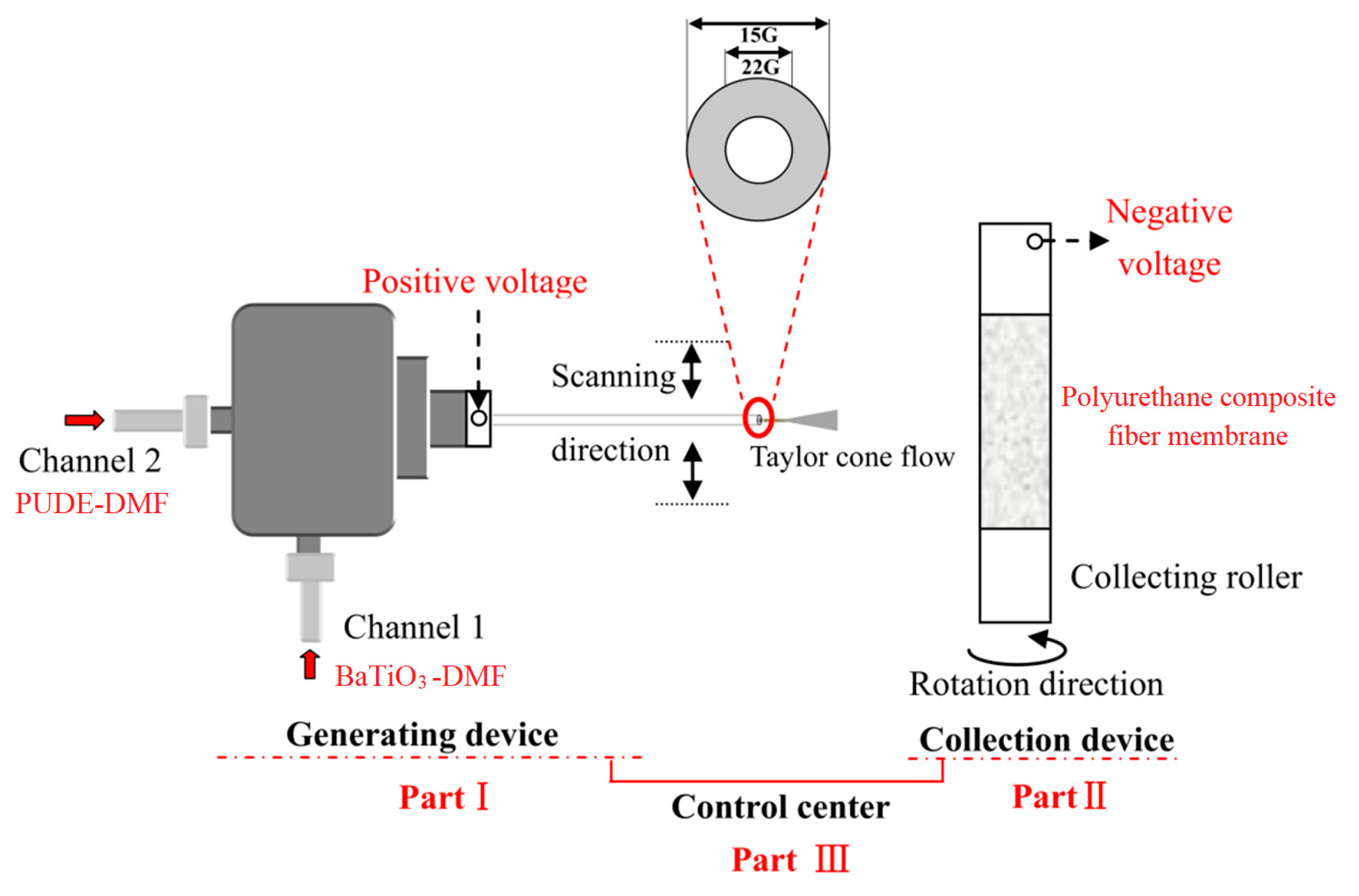
3 of 100:0, 100:0.5, 100:1.0, and 100:1.5 were obtained by adjusting the coaxial spinning parameters. The principles of the coaxial spinning technology are shown in
Figure 3.
As shown in
Figure 3, the coaxial spinning device is composed of three parts: fiber generation, fiber membrane collection, and control. Specifically, the liquid ejected from the spinning head will form a Taylor cone flow under the action of high voltage that will be collected on the collection roller. During that time, the morphology of the composite fiber membrane and the filling state of BaTiO
3 can be controlled by adjusting the voltage, the scanning speed, the ejection speed, the speed of the collection roller, and the environmental factors (temperature and humidity) of the device. In this way, the polyurethane composite fiber membrane with the target morphology can be obtained. After adjustment, the main coaxial spinning parameters are as follows: spinning solution concentration 20%, pushing speed 0.7 mL/h, voltage 12.5 kV, spinning head size 22 G, humidity no more than 25%, temperature no more than 55 °C.
- (2)
Packaging of polyurethane composite fiber membrane actuating unit
The packaging of polyurethane composite fiber membrane actuating units mainly involves the selection of a flexible electrode, coating method, and fiber membrane pre stretching rate. This study focuses on the selection of the flexible electrode and the coating method only. The pre stretching ratio is set to 2, and the circular insulating epoxy resin (2 mm) is selected as the constraint frame.
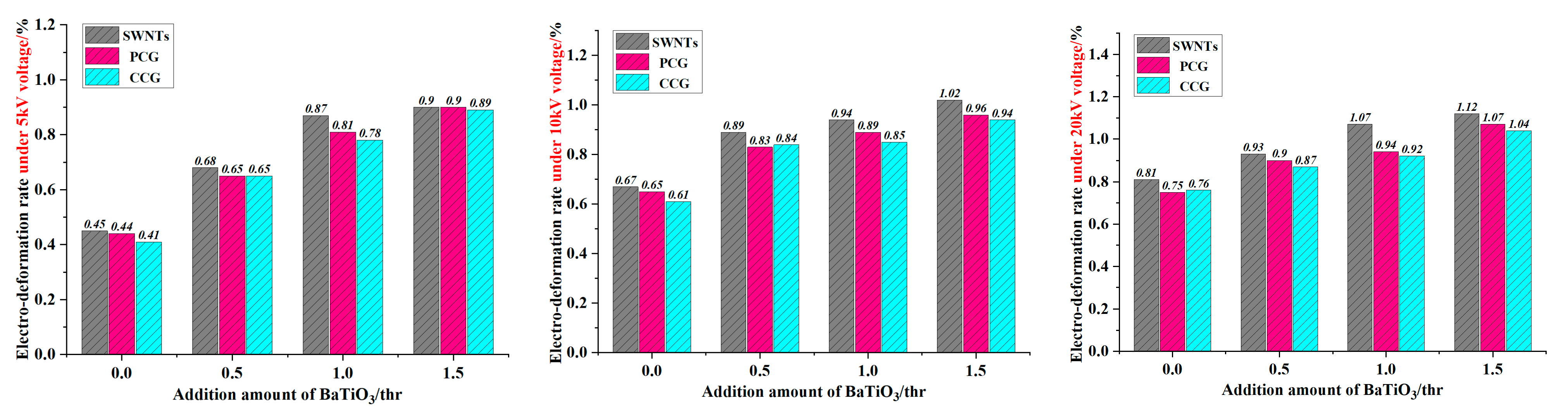
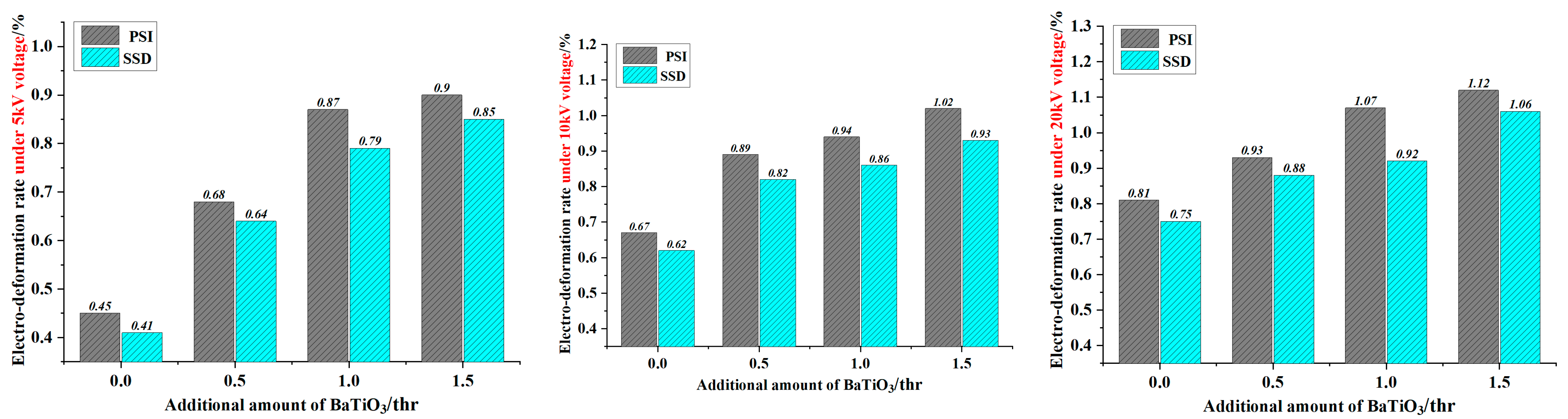
Specifically, three kinds of flexible electrode are selected: single-walled carbon nanotubes (SWNTs), perfluoropolyether conductive grease (PCG), and conductive carbon grease (CCG). Among them, the SWNTs are coated using physical surface implantation (PSI) and solvent suspension dispersion (SSD). The former method involves arranging and stacking the single-walled carbon nanotubes on the surface of the dielectric fiber membrane to form a flexible electrode. The latter involves dispersing the carbon nanotubes in the ether solution through ultrasonic oscillation and then coating the suspension on the surface of the fiber membrane to form an electrode under the volatilization of the solvent. Additionally, the other two electrodes can be coated directly with cotton swabs.
Specifically, the fiber film is pre stretched and constrained by epoxy frame; then, flexible electrodes are coated on the upper and lower surfaces of the film, and finally, copper foil is drawn out. The electrode mass used on the upper and lower surfaces of the film is 20 mg, and the diameter of the coating surface is 10 mm.
2.4. Testing Methods
- (1)
Micro morphology characterization
The surface morphology of the fiber membrane and the arrangement of BaTiO
3 in the fiber bundle are observed by the electron microscope. The equipment information is shown in
Table 3.
- (2)
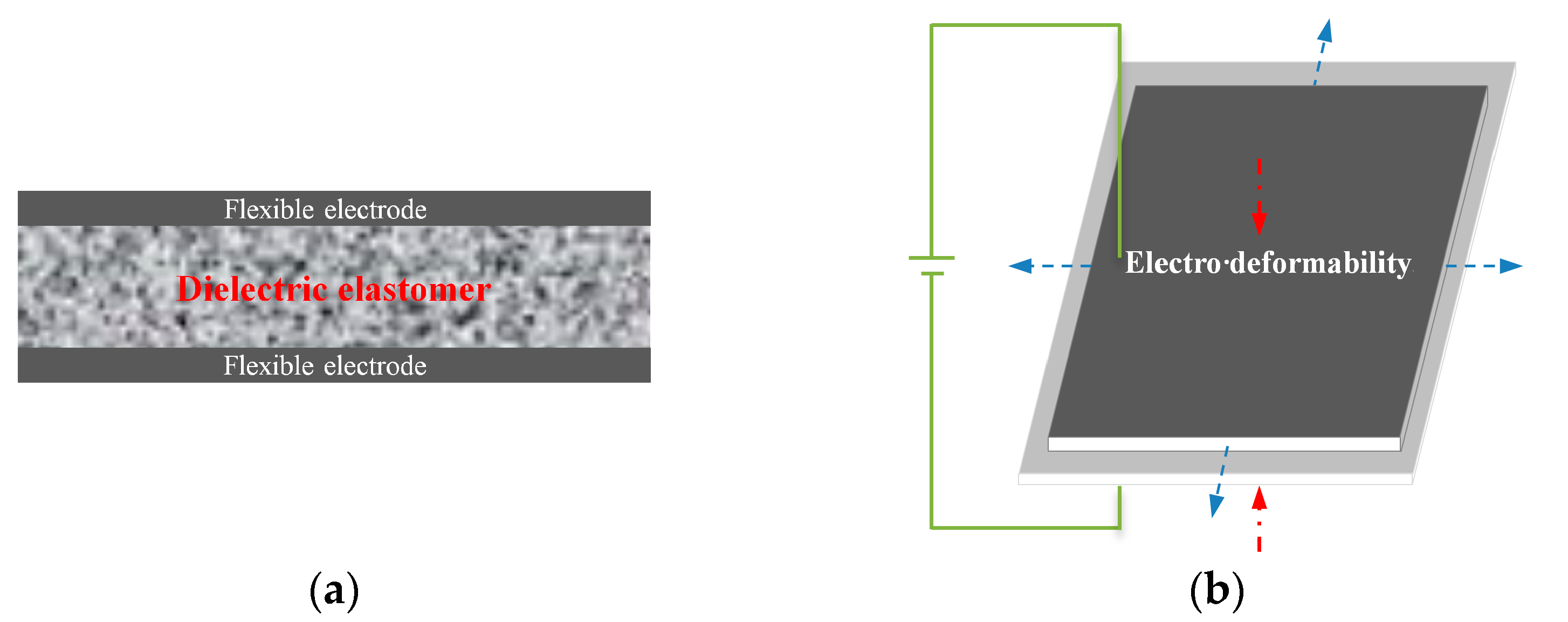
Electro deformability test
The first step before the electrical deformation test is to test the dielectric sensitivity factor. Considering that the dielectric sensitivity factor β is expressed in Equation (1), the dielectric constant and elastic modulus are tested as follows.
It can be seen from this equation that for the dielectric material, the greater the dielectric constant and the lower the elastic modulus, the higher the dielectric sensitivity. Therefore, it is essential to balance the elastic modulus of materials while improving the dielectric properties of materials.
The dielectric properties of the samples are measured using the dielectric constant tester of model 6632-1s from the Teng Skye company. The test frequency ranges from 10 Hz to 500 Hz, the test temperature is room temperature, and the sample size is 10 mm.
Following the national standard GB/T 528-1998, the sample is cut into multiple 2 mm × 5 mm × 2 mm dumbbell-shaped splines at a tensile rate of 200 mm/min. The elastic modulus is calculated based on the slope of the initial part (deformation less than 5%) on the stress–strain curve. It is necessary to take the median value of five parallel test values [
16].
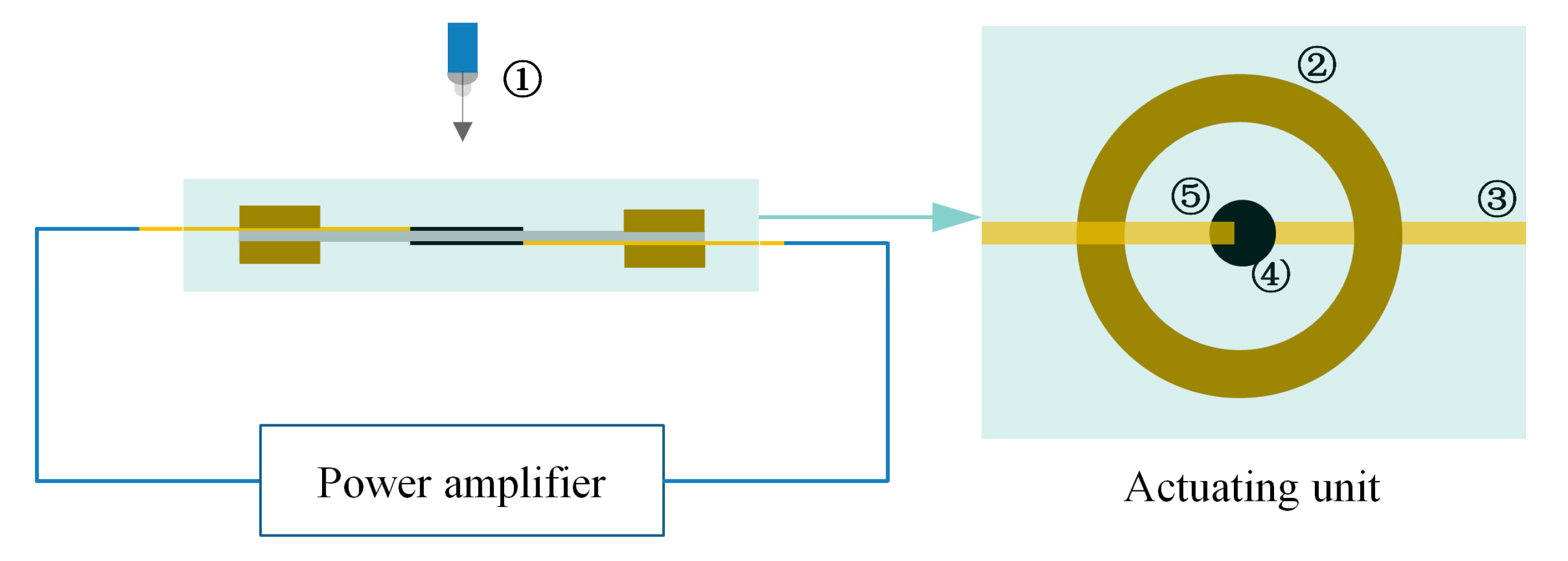
The next step is to verify the dielectric sensitivity factor, i.e., the test of electro deformation. The upper and lower surfaces of the flexible electrodes are led out with copper foil, and then the outgoing line is connected to the power amplifier; the machine information is as follows: RK2674A/DC 10 mA, the maximum output voltage is 20 kV, Shenzhen meirike Electronic Technology Co., Ltd. (Shenzhen, China). In addition, the focus of the high-speed camera is aligned with the flexible electrode covering part. Finally, the output voltage is adjusted through the power amplifier, and the camera can collect the electro deformability of the flexible electrode under the voltage. The electro deformability rate (
SA) of the polyurethane fiber membrane actuating unit can be obtained through data processing, as shown in Equation (2). The test platform is shown in
Figure 4.
where
S1 and
S2 represent the area of the coated electrode area before and after deformation of the actuating unit, respectively.


