
Enhancing the Permeate Flux Improvement of Direct Contact Membrane Distillation Modules with Inserted S-Ribs Carbon-Fiber Filaments

 ,
,  , ,
, ,
Abstract
1. Introduction
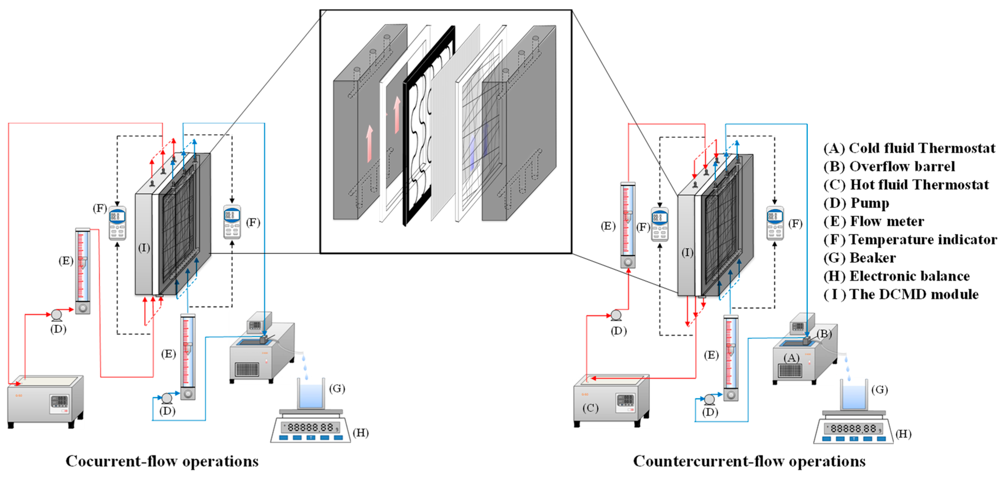
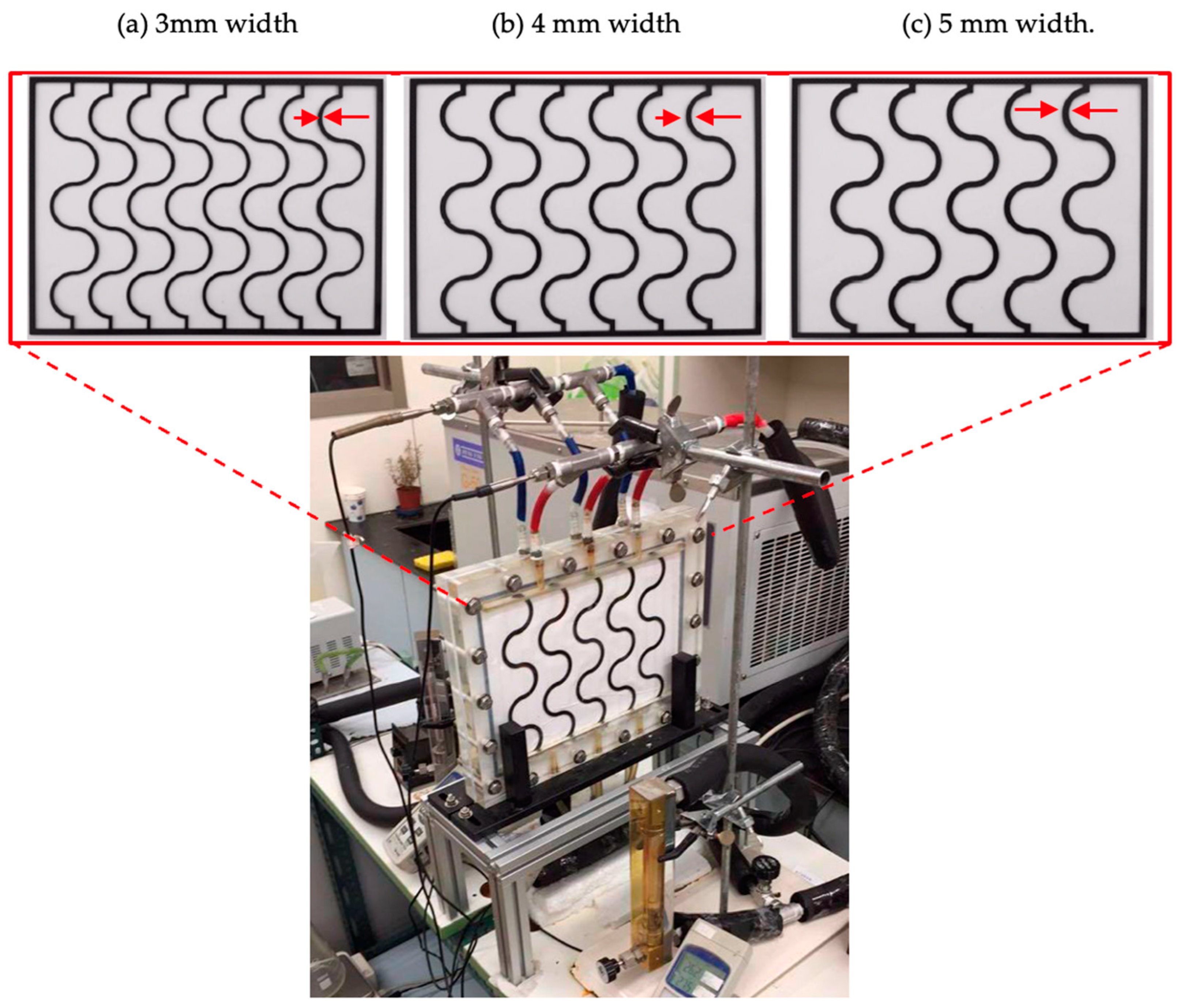
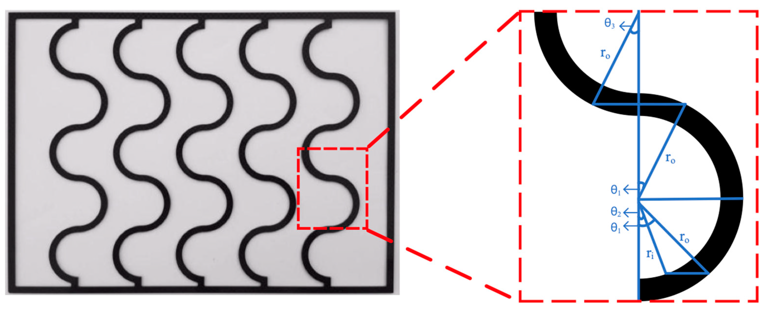
2. Experimental Setup and Materials
3. Theoretical Formulations
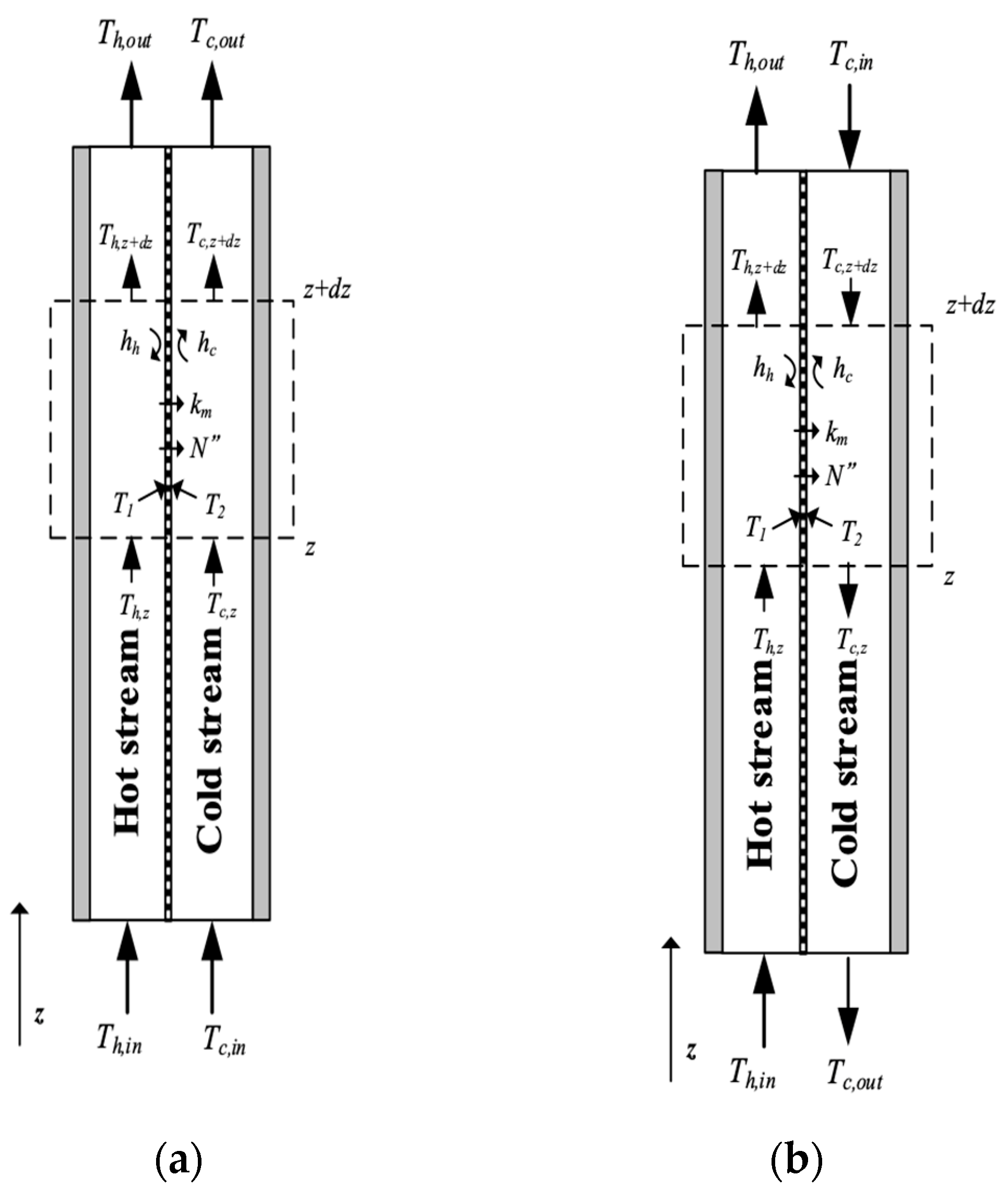
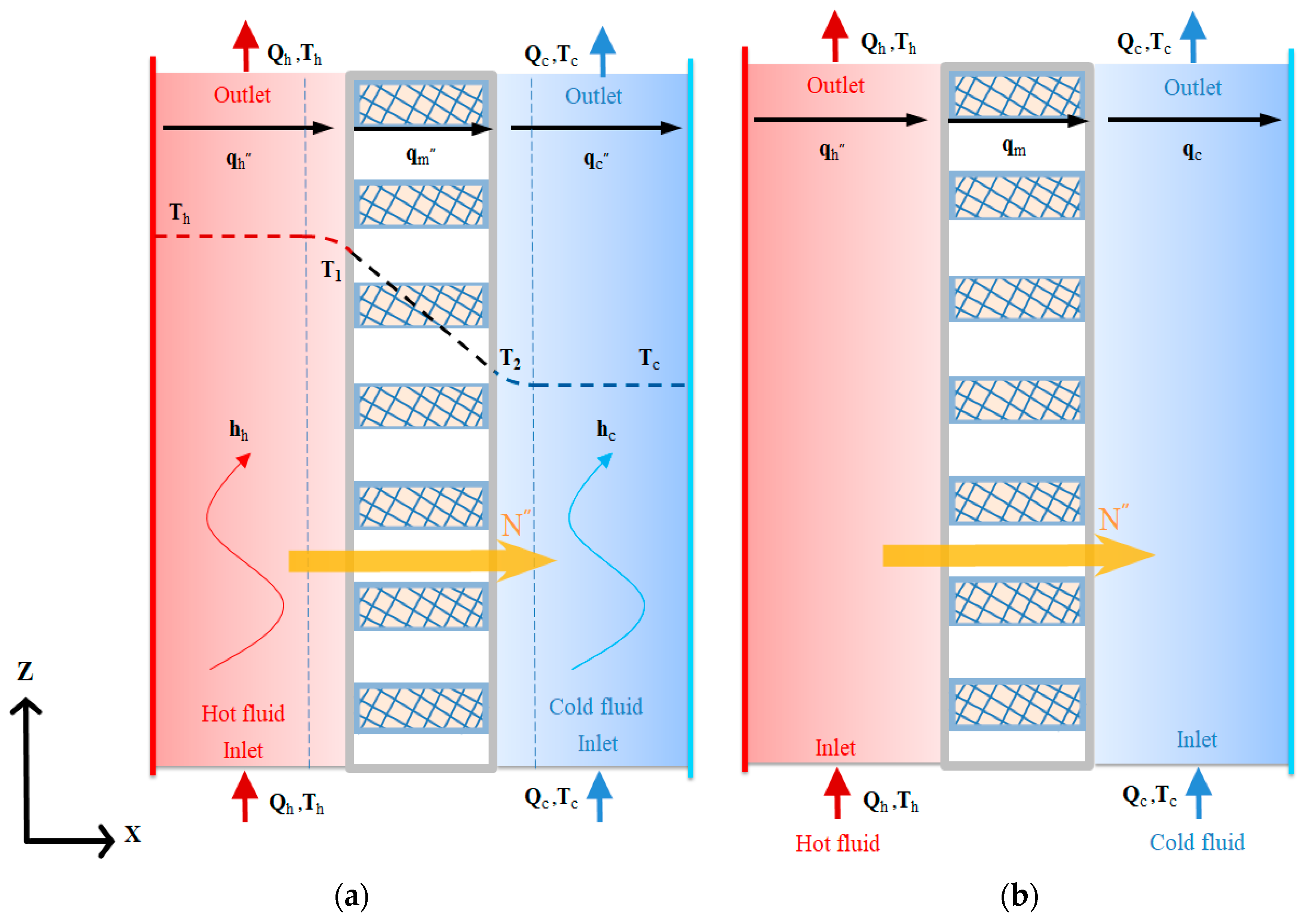
3.1. Mass and Heat Transfer
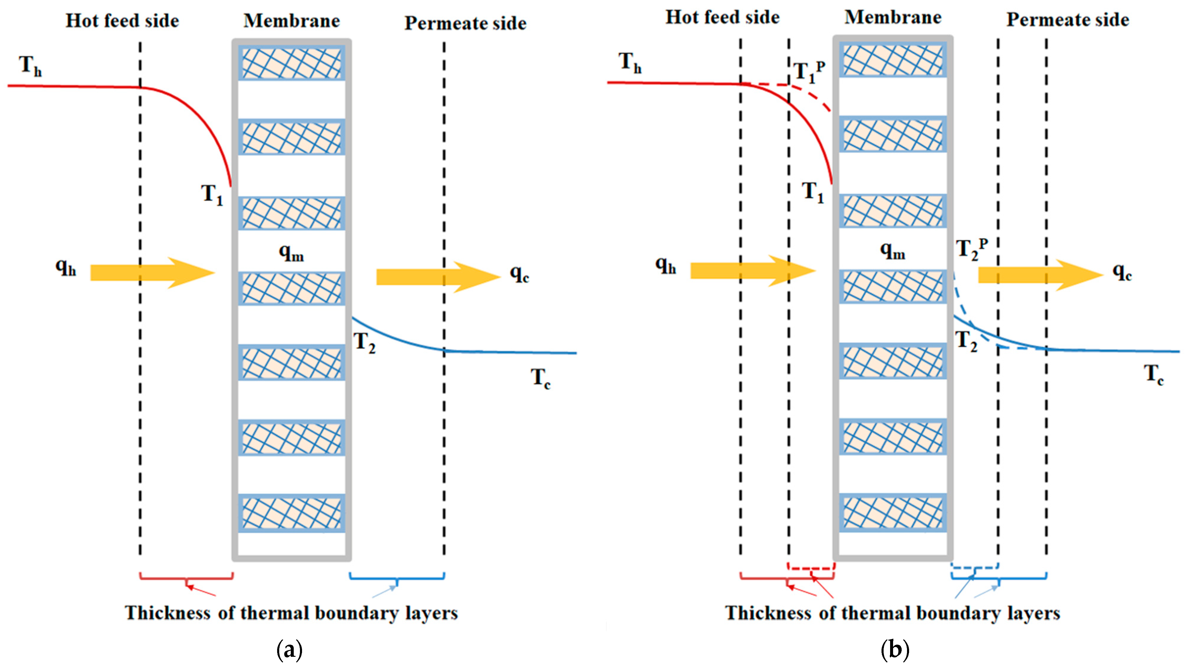
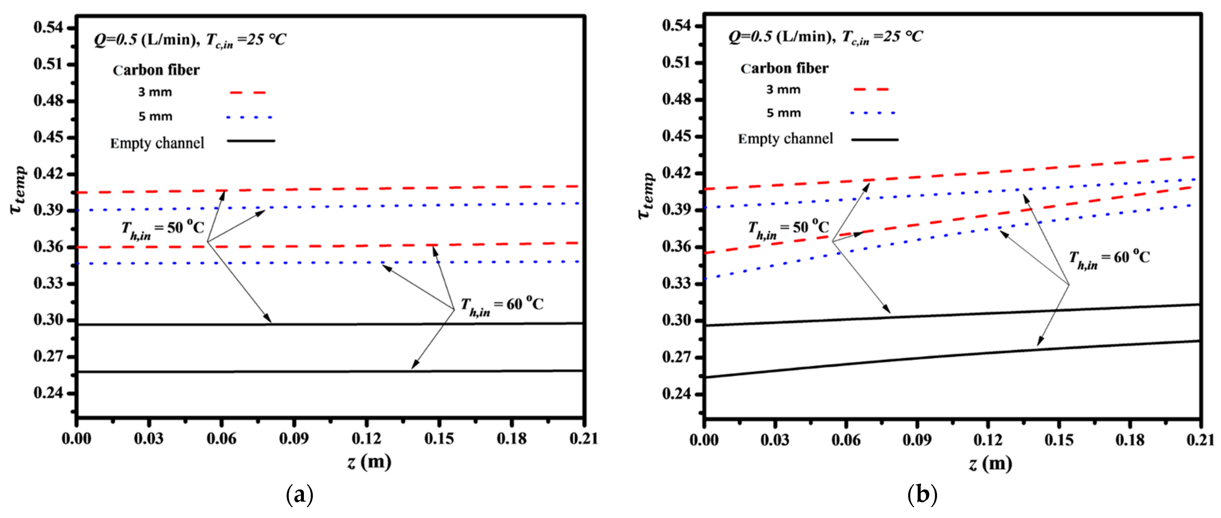
3.2. Temperature Polarization Coefficient
3.3. Governing Equations by Macroscopic Modeling
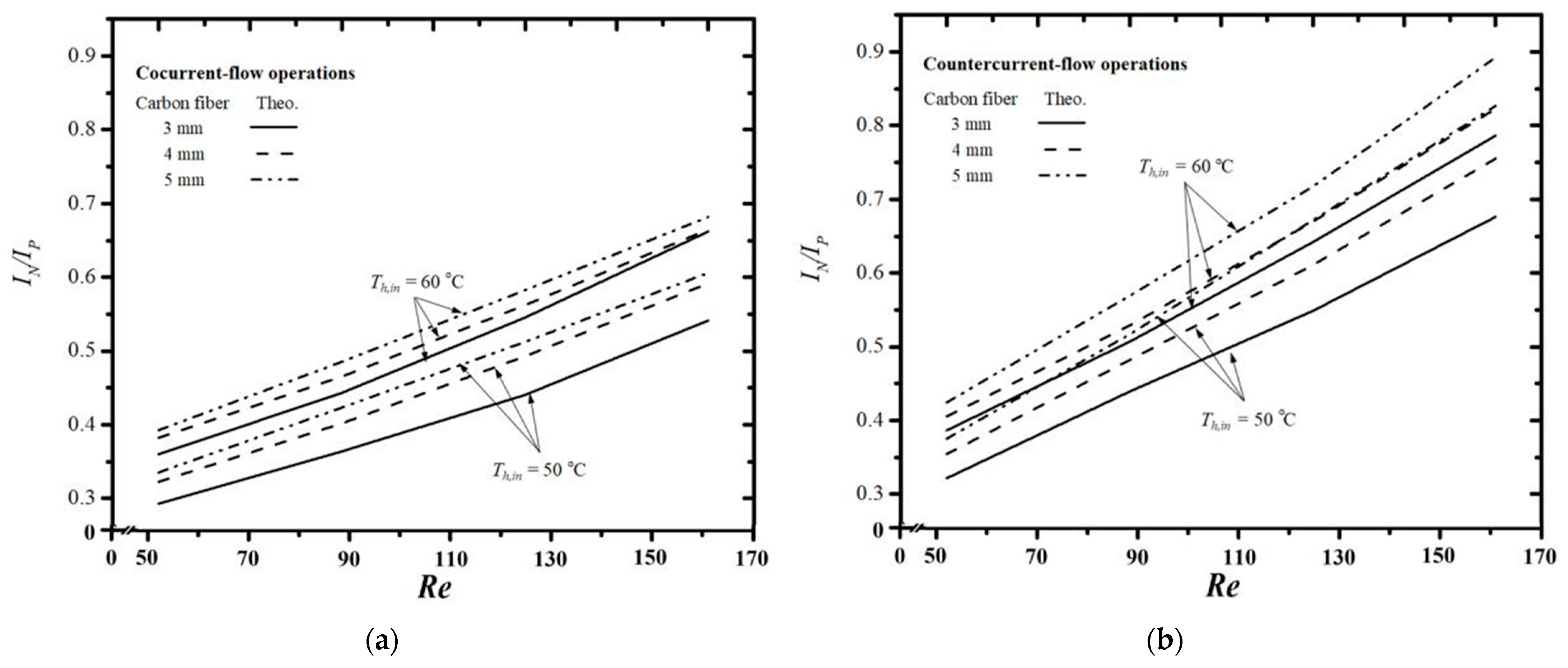
3.4. Hydraulic Consumption Increment
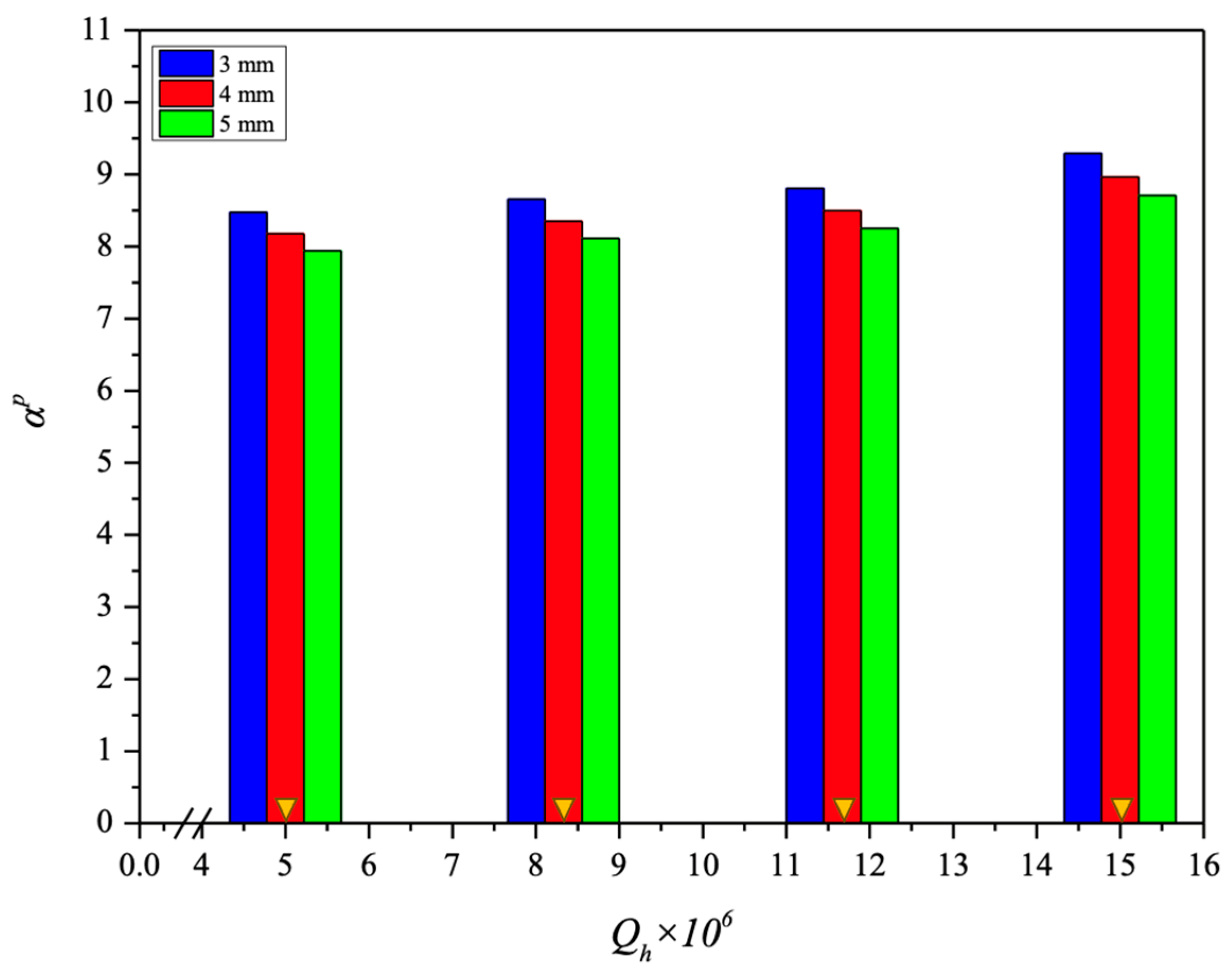
3.5. Heat-Transfer Enhancement Factor
4. Results and Discussions
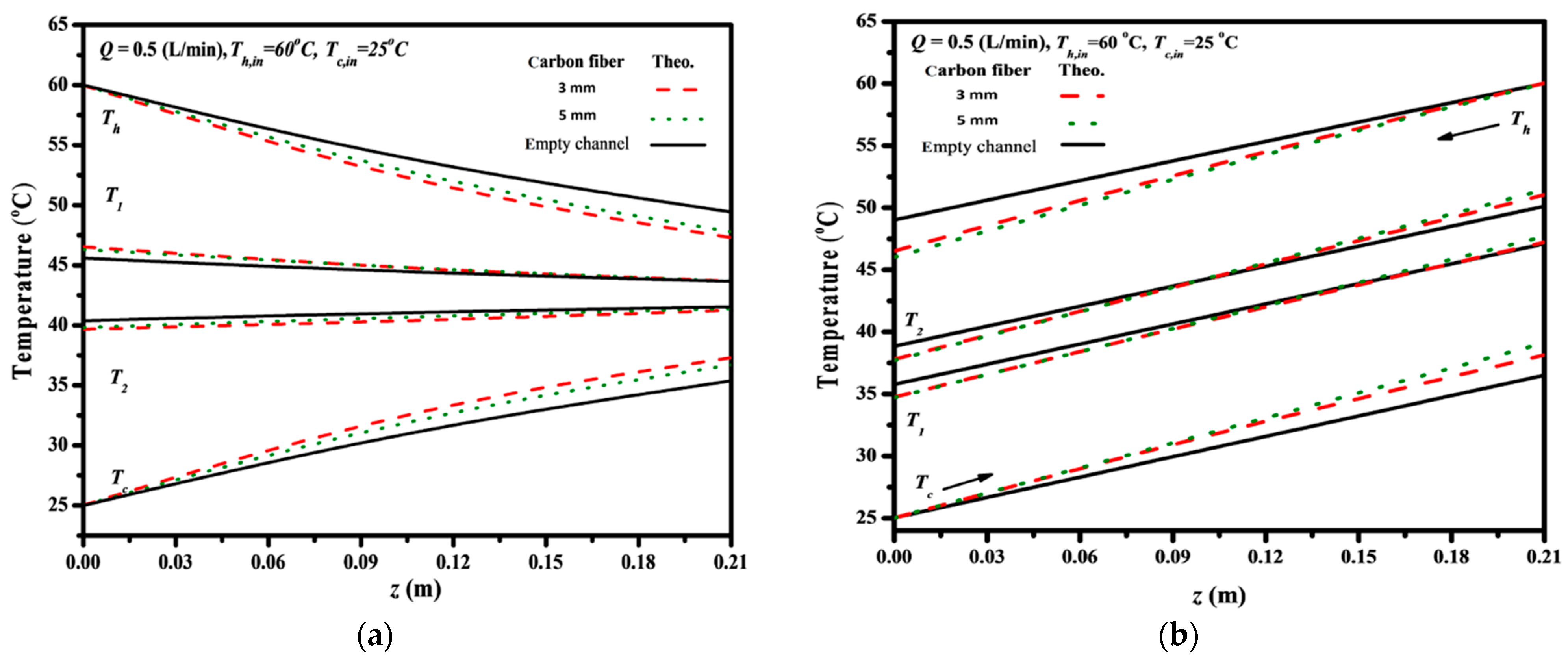
4.1. Lessening Temperature Polarization Effect by Inserting Carbon-Fiber Filaments
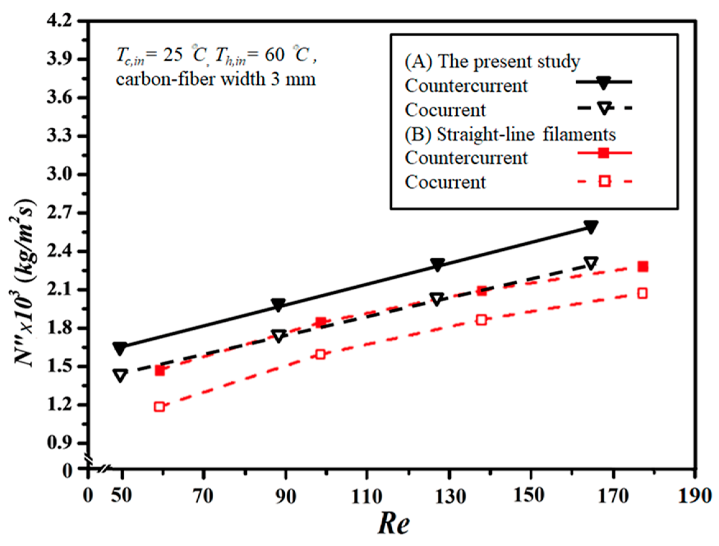
4.2. Permeate Flux Enhancement by Inserting S-Ribs Carbon-Fiber Turbulence Promoters
4.3. Accuracy Deviations between Experimental and Theoretical Results
4.4. Energy Consumption Increment
5. Conclusions
- Inserting S-ribs carbon-fiber filaments of 3 mm in width into the saline feed flow channel results in relative increases in permeate flux up to a maximum permeate flux improvement of 37.77% under countercurrent-flow operations compared to the module using an empty channel.
- The results show that permeate flux improvement decreases with the width of carbon-fiber filaments, but the ratio of permeate flux improvement to power consumption increment (say ) increases with the width of carbon-fiber filaments.
- Permeate flux improvement is more pronounced in countercurrent-flow operations compared to cocurrent-flow operations due to the attainment of a larger temperature gradient.
Author Contributions
Funding
Institutional Review Board Statement
Informed Consent Statement
Data Availability Statement
Acknowledgments
Conflicts of Interest
Abbreviations
| Cross-sectional area of flow channel (m2) | |
| Water activity in NaCl solution | |
| Friction losses coefficient | |
| Heat capacity () | |
| Membrane coefficient based on the Knudsen diffusion model () | |
| Membrane coefficient based on the molecular diffusion model () | |
| Membrane permeation coefficient () | |
| Channel height (m) | |
| Carbon-fiber thickness (m) | |
| Diffusion coefficient of air and vapor in the membrane () | |
| Hydraulic equivalent hdiameter of channel (m), | |
| The heat-transfer equivalent diameter (m) | |
| Accuracy deviation of experimental results from the theoretical predictions | |
| Fanning friction factor, | |
| Convective heat-transfer coefficient of cold feed (W ) | |
| Convective heat-transfer coefficient of hot saline feed (W ) | |
| Convective heat-transfer coefficient of hot saline feed with promoter insertion (W ) | |
| Hydraulic dissipate energy (W), | |
| Permeate flux relative factor | |
| Power consumption relative index | |
| Thermal conductivity of water () | |
| Thermal conductivity of gas () | |
| Thermal conductivity of membrane () | |
| Thermal conductivity of solid membrane () | |
| Channel length (m) | |
| Friction loss (J kg−1), | |
| Molecular weight of water (kg mol−1) | |
| Number of carbon-fiber filaments | |
| Distillate flux () | |
| Average distillate flux () | |
| Number of experimental measurements | |
| Enhanced dimensionless Nusselt number | |
| Nusselt number for laminar flow | |
| Mean saturated pressure in membrane (Pa) | |
| Saturation vapor pressure (Pa) | |
| Volumetric flow rate (m3 s−1) | |
| Heat flux () | |
| Membrane pore radius (m) | |
| Gas constant (8.314 J mol−1 K−1) | |
| Reynolds number | |
| Precision index of an experimental measurements of permeate flux (kg m−2 s−1) | |
| Mean value of (kg m−2 s−1) | |
| Membrane surface temperature in the hot saline feed region (°C) | |
| Membrane surface temperature in the cold feed region (°C) | |
| Membrane surface temperature with promoter insertion in the hot saline feed region (°C) | |
| Membrane surface temperature with promoter insertion in the cold feed region (°C) | |
| Mean temperature in membrane (°C) | |
| Average velocity () | |
| Width of channel (m) | |
| Carbon-fiber width (m) | |
| Liquid mole fraction of water | |
| Mole fraction of NaCl in saline solution | |
| Vapor mole fraction of water | |
| Natural log mean Vapor mole fraction of water in the membrane | |
| Axial coordinate along the flow direction (m) | |
| Greek letters | |
| Enhancement factor | |
| Thickness of membrane (µm) | |
| ε | Membrane porosity |
| Gas viscosity () | |
| Latent heat of water () | |
| Viscosity () | |
| Density () | |
| Membrane tortuosity | |
| Temperature polarization coefficients | |
| Subscripts | |
| 1 | Membrane surface on hot fluid side |
| Membrane surface on cold fluid side | |
| c | Cold feed stream |
| h | Hot feed stream |
| cor. | Correlated results |
| empty | Channel without embedding turbulence promoters |
| exp. | Experimental results |
| in | At the inlet |
| Laminar flow | |
| out | At the outlet |
| promoter | Channel with embedding turbulence promoters |
| theo | Theoretical predictions |
References
- Lawson, K.W.; Lloyd, D.R. Membrane distillation. II. Direct contact MD. J. Membr. Sci. 1996, 120, 123–133. [Google Scholar] [CrossRef]
- Khayet, M. Membranes and theoretical modeling of membrane distillation: A review. Adv. Colloid Interface Sci. 2011, 164, 56–88. [Google Scholar] [CrossRef] [PubMed]
- Al-Obaidani, S.; Curcio, E.; Macedonio, F.; Profio, G.D.; Al-Hinai, H.; Drioli, E. Potential of membrane distillation in seawater desalination: Thermal efficiency, sensitivity study and cost estimation. J. Membr. Sci. 2008, 323, 85–98. [Google Scholar] [CrossRef]
- Huang, Y.-X.; Wang, Z.; Horseman, T.; Livingston, J.L.; Lin, S. Interpreting contact angles of surfactant solutions on microporous hydrophobic membranes. J. Membr. Sci. Lett. 2022, 2, 100015. [Google Scholar] [CrossRef]
- Martínez-Díez, L.; Vazquez-Gonzalez, M.I. Temperature and concentration polarizationin membrane distillation of aqueous salt solutions. J. Membr. Sci. 1999, 156, 265–273. [Google Scholar] [CrossRef]
- El-Bourawi, M.S.; Ding, Z.; Ma, R.; Khayet, M. A framework for better understanding membrane distillation separation process. J. Membr. Sci. 2006, 285, 4–29. [Google Scholar] [CrossRef]
- Yun, Y.; Ma, R.; Zhang, W.; Fane, A.; Li, J. Direct contact membrane distillation mechanism for high concentration NaCl solutions. Desalination 2006, 188, 251–262. [Google Scholar] [CrossRef]
- Ali, A.; Macedonio, F.; Drioli, E.; Aljlil, S.; Alharbi, O.A. Experimental and theoretical evaluation of temperature polarization phenomenon in direct contact membrane distillation. Chem. Eng. Res. Des. 2013, 91, 1966–1977. [Google Scholar] [CrossRef]
- Martínez-Díez, L.; Vázquez-González, M.I. Effects of Polarization on Mass Transport through Hydrophobic Porous Membranes. Ind. Eng. Chem. Res. 1998, 37, 4128–4135. [Google Scholar] [CrossRef]
- Ho, C.-D.; Chang, H.; Chang, C.-L.; Huang, C.-H. Theoretical and experimental studies of flux enhancement with roughened surface in direct contact membrane distillation desalination. J. Membr. Sci. 2013, 433, 160–166. [Google Scholar] [CrossRef]
- Phattaranawik, J.; Jiraratananon, R.; Fane, A.G. Effects of net-type spacers on heat and mass transfer in direct contact membrane distillation and comparison with ultrafiltration studies. J. Membr. Sci. 2003, 217, 193–206. [Google Scholar] [CrossRef]
- Yang, X.; Yu, H.; Wang, R.; Fane, A.G. Analysis of the effect of turbulence promoters in hollow fiber membrane distillation modules by computational fluid dynamic (CFD) simulations. J. Membr. Sci. 2012, 415–416, 758–769. [Google Scholar] [CrossRef]
- Thomas, N.; Sreedhar, N.; Al-Ketan, O.; Rowshan, R.; Abu Al-Rub, R.K.; Arafat, H. 3D printed triply periodic minimal surfaces as spacers for enhanced heat and mass transfer in membrane distillation. Desalination 2018, 443, 256–271. [Google Scholar] [CrossRef]
- Lee, J.-Y.; Tan, W.S.; An, J.; Chua, C.K.; Tang, C.Y.; Fane, A.G.; Chong, T.H. The potential to enhance membrane module design with 3D printing technology. J. Membr. Sci. 2016, 499, 480–490. [Google Scholar] [CrossRef]
- Tsai, H.-Y.; Huang, A.; Soesanto, J.F.; Luo, Y.-L.; Hsu, T.-Y.; Chen, C.-H.; Hwang, K.-J.; Ho, C.-D.; Tung, K.-L. 3D printing design of turbulence promoters in a cross-flow microfiltration system for fine particles removal. J. Membr. Sci. 2018, 573, 647–656. [Google Scholar] [CrossRef]
- Lee, J.-G.; Kim, Y.-D.; Kim, W.-S.; Francis, L.; Amy, G.; Ghaffour, N. Performance modeling of direct contact membrane distillation (DCMD) seawater desalination process using a commercial composite membrane. J. Membr. Sci. 2015, 478, 85–95. [Google Scholar] [CrossRef]
- Chen, L.-H.; Huang, A.; Chen, Y.-R.; Chen, C.-H.; Hsu, C.-C.; Tsai, F.-Y.; Tung, K.-L. Omniphobic membranes for direct contact membrane distillation: Effective deposition of zinc oxide nanoparticles. Desalination 2018, 428, 255–263. [Google Scholar] [CrossRef]
- Martínez-Díez, L.; Vázquez-González, M.; Florido-Díaz, F. Study of membrane distillation using channel spacers. J. Membr. Sci. 1998, 144, 45–56. [Google Scholar] [CrossRef]
- Santos, J.L.C.; Geraldes, V.; Velizarov, S.; Crespo, J.G. Investigation of flow patterns and mass transfer in membrane module channels filled with flow-aligned spacers using computational fluid dynamics (CFD). J. Membr. Sci. 2007, 305, 103–117. [Google Scholar] [CrossRef]
- Schofield, R.W.; Fane, A.G.; Fell, C.J.D. Heat and mass transfer in membrane distillation. J. Membr. Sci. 1987, 33, 299–313. [Google Scholar] [CrossRef]
- Dong, Y.; Dai, X.; Zhao, L.; Gao, L.; Xie, Z.; Zhang, J. Review of Transport Phenomena and Popular Modelling Approaches in Membrane Distillation. Membranes 2021, 11, 122. [Google Scholar] [CrossRef] [PubMed]
- Shakaib, M.; Hasani, S.M.F.; Ahmed, I.; Yunus, R.M. A CFD study on the effect of spacer orientation on temperature polarization in membrane distillation modules. Desalination 2012, 284, 332–340. [Google Scholar] [CrossRef]
- Chang, H.; Hsu, J.-A.; Chang, C.-L.; Ho, C.-D.; Cheng, T.-W. Simulation study of transfer characteristics for spacer-filled membrane distillation desalination modules. Appl. Energy 2017, 185, 2045–2057. [Google Scholar] [CrossRef]
- Phattaranawik, J.; Jiraratananon, R.; Fane, A.G. Heat transport and membrane distillation coefficients in direct contact membrane distillation. J. Membr. Sci. 2003, 212, 177–193. [Google Scholar] [CrossRef]
- Bird, R.B.; Stewart, W.E.; Lightfoot, E.N. Transport Phenomena; Wiley: New York, NY, USA, 1960. [Google Scholar]
- Mills, A.F. Mass Transfer, 2nd ed.; Prentice-Hall: Englewood Cliffs, NJ, USA, 2001. [Google Scholar]
- Da Costa, A.; Fane, A.; Wiley, D. Spacer characterization and pressure drop modelling in spacer-filled channels for ultrafiltration. J. Membr. Sci. 1994, 87, 79–98. [Google Scholar] [CrossRef]
- Taamneh, Y.; Bataineh, K. Improving the performance of direct contact membrane distillation utilizing spacer-filled channel. Desalination 2017, 408, 25–35. [Google Scholar] [CrossRef]
- Ho, C.D.; Chang, H.; Tsai, C.H.; Lin, P.H. Theoretical and experimental studies of a compact multi-unit direct contact membrane distillation module. Ind. Eng. Chem. Res. 2016, 55, 5385–5394. [Google Scholar]
- Fukazawa, T.; Kawamura, H.; Tamura, T. Water Vapour Resistance of Hydrophobic Microporous Membranes under Reduced Pressures at a Constant Temperature. J. Text. Inst. 1999, 90 Pt 1, 602–615. [Google Scholar] [CrossRef]
- Lawson, K.W.; Lloyd, D.R. Membrane distillation. J. Membr. Sci. 1997, 124, 1–25. [Google Scholar] [CrossRef]
- Schofield, R.W.; Fane, A.G.; Fell, C.J.D. Gas and vapor transport through microporous membranes. I. Knudsen-Poiseuille transition. J. Membr. Sci. 1990, 53, 159–171. [Google Scholar] [CrossRef]
- Ding, Z.; Ma, R.; Fane, A. A new model for mass transfer in direct contact membrane distillation. Desalination 2003, 151, 217–227. [Google Scholar] [CrossRef]
- Zhang, J.; Gray, S.; Li, J.-D. Modelling heat and mass transfers in DCMD using compressible membranes. J. Membr. Sci. 2012, 387–388, 7–16. [Google Scholar] [CrossRef]
- Iversen, S.; Bhatia, V.; Dam-Johansen, K.; Jonsson, G. Characterization of microporous membranes for use in membrane contactors. J. Membr. Sci. 1997, 130, 205–217. [Google Scholar] [CrossRef]
- Warner, S.B. Fiber Science; Princeton-Hall: Englewood Cliffs, NJ, USA, 1995. [Google Scholar]
- Welty, J.R.; Wick, C.E.; Wilson, R.E. Fundamentals of Momentum, Heat, and Mass Transfer, 3rd ed.; John Wiley & Sons: New York, NY, USA, 1984. [Google Scholar]
- Kakac, S.; Shah, R.K.; Aung, W. Handbook of Single-Phase Convective Heat Transfer; Wiley: New York, NY, USA, 1987. [Google Scholar]
- Phattaranawik, J.; Jiraratananon, R.; Fane, A.G. Effect of pore size distribution and air flux on mass transport in direct contact membrane distillation. J. Membr. Sci. 2003, 215, 75–85. [Google Scholar] [CrossRef]
- Kern, D.Q. Process Heat Transfer; McGraw-Hill: New York, NY, USA, 1950. [Google Scholar]
- Moffat, R.J. Describing the uncertainties in experimental results. Exp. Therm. Fluid Sci. 1988, 1, 3–17. [Google Scholar] [CrossRef]
 Hot fluid;
  Cold fluid;
  Permeate flux;
  Heat flux).
Hot fluid; Cold fluid; Permeate flux; Heat flux).
Heat flux).
Hot fluid; Cold fluid; Permeate flux; Heat flux). Hot fluid; Cold fluid; Permeate flux).
Hot fluid; Cold fluid; Permeate flux).
Hot fluid; Cold fluid; Permeate flux).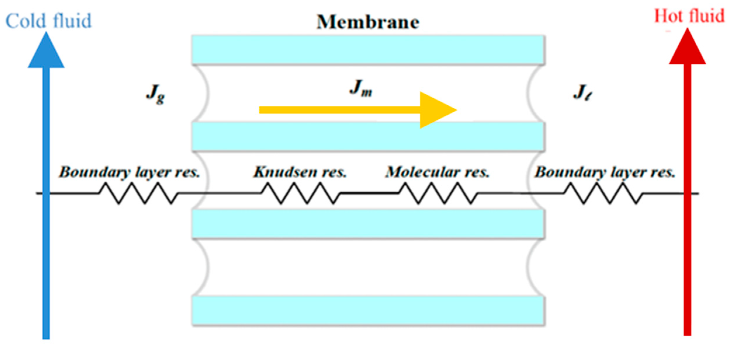


(°C) | (L/min) | Empty | 3 mm | 4 mm | 5 mm | |||
|---|---|---|---|---|---|---|---|---|
| (kg m−2 h−1) | (kg m−2 h−1) | (%) | (kg m−2 h−1) | (%) | (kg m−2 h−1) | (%) | ||
| 50 | Cocurrent-flow operations | |||||||
| 0.3 | 0.75 | 0.85 | 14.06 | 0.84 | 12.58 | 0.83 | 11.37 | |
| 0.5 | 9.00 | 1.06 | 17.46 | 1.04 | 15.68 | 1.03 | 14.35 | |
| 0.7 | 1.05 | 1.27 | 21.14 | 1.25 | 19.24 | 1.23 | 17.37 | |
| 0.9 | 1.10 | 1.39 | 26.00 | 1.35 | 23.10 | 1.33 | 20.55 | |
| 60 | 0.3 | 1.21 | 1.42 | 17.27 | 1.39 | 14.92 | 1.37 | 13.31 |
| 0.5 | 1.41 | 1.71 | 21.28 | 1.67 | 18.16 | 1.64 | 16.45 | |
| 0.7 | 1.60 | 2.02 | 26.19 | 1.95 | 21.94 | 1.92 | 19.75 | |
| 0.9 | 1.73 | 2.28 | 31.79 | 2.18 | 25.95 | 2.13 | 23.12 | |
| 50 | Countercurrent-flow operations | |||||||
| 0.3 | 0.87 | 1.00 | 15.44 | 0.99 | 13.82 | 0.98 | 12.73 | |
| 0.5 | 1.01 | 1.22 | 21.09 | 1.20 | 18.81 | 1.19 | 17.52 | |
| 0.7 | 1.12 | 1.42 | 26.34 | 1.39 | 23.84 | 1.38 | 22.77 | |
| 0.9 | 1.17 | 1.55 | 32.48 | 1.52 | 29.49 | 1.50 | 28.03 | |
| 60 | 0.3 | 1.39 | 1.65 | 18.56 | 1.61 | 15.83 | 1.59 | 14.39 |
| 0.5 | 1.57 | 1.95 | 24.33 | 1.89 | 20.64 | 1.87 | 19.30 | |
| 0.7 | 1.75 | 2.29 | 30.82 | 2.21 | 26.14 | 2.18 | 24.31 | |
| 0.9 | 1.88 | 2.59 | 37.77 | 2.48 | 32.13 | 2.45 | 30.27 | |
Disclaimer/Publisher’s Note: The statements, opinions and data contained in all publications are solely those of the individual author(s) and contributor(s) and not of MDPI and/or the editor(s). MDPI and/or the editor(s) disclaim responsibility for any injury to people or property resulting from any ideas, methods, instructions or products referred to in the content. |
© 2024 by the authors. Licensee MDPI, Basel, Switzerland. This article is an open access article distributed under the terms and conditions of the Creative Commons Attribution (CC BY) license (https://creativecommons.org/licenses/by/4.0/).
Share and Cite
Ho, C.-D.; Wang, Y.-W.; Chao, Y.; Chew, T.L.; Jiang, M.-S.; Chen, J.-H.; Li, C.-Y. Enhancing the Permeate Flux Improvement of Direct Contact Membrane Distillation Modules with Inserted S-Ribs Carbon-Fiber Filaments. Membranes 2024, 14, 98. https://doi.org/10.3390/membranes14050098
Ho C-D, Wang Y-W, Chao Y, Chew TL, Jiang M-S, Chen J-H, Li C-Y. Enhancing the Permeate Flux Improvement of Direct Contact Membrane Distillation Modules with Inserted S-Ribs Carbon-Fiber Filaments. Membranes. 2024; 14(5):98. https://doi.org/10.3390/membranes14050098
Chicago/Turabian StyleHo, Chii-Dong, Yi-Wun Wang, Yi Chao, Thiam Leng Chew, Ming-Shen Jiang, Jian-Har Chen, and Ching-Yu Li. 2024. "Enhancing the Permeate Flux Improvement of Direct Contact Membrane Distillation Modules with Inserted S-Ribs Carbon-Fiber Filaments" Membranes 14, no. 5: 98. https://doi.org/10.3390/membranes14050098
APA StyleHo, C.-D., Wang, Y.-W., Chao, Y., Chew, T. L., Jiang, M.-S., Chen, J.-H., & Li, C.-Y. (2024). Enhancing the Permeate Flux Improvement of Direct Contact Membrane Distillation Modules with Inserted S-Ribs Carbon-Fiber Filaments. Membranes, 14(5), 98. https://doi.org/10.3390/membranes14050098