Article

Experimental Investigation of the Performance of a Tuned Heave Plate Energy Harvesting System for a Semi-Submersible Platform

1
School of Civil Engineering and Transportation, South China University of Technology, Guangzhou 510640, China
2
School of Civil Engineering, Qingdao University of Technology, Qingdao 266033, China
3
School of Civil Engineering, Harbin Institute of Technology, Harbin 150090, China
4
State Key Laboratory of Coastal and Offshore Engineering, Dalian University of Technology, Dalian 116024, China
*
Author to whom correspondence should be addressed.
J. Mar. Sci. Eng. 2022, 10(1), 45; https://doi.org/10.3390/jmse10010045
Submission received: 13 November 2021 / Revised: 10 December 2021 / Accepted: 21 December 2021 / Published: 1 January 2022
(This article belongs to the Special Issue Recent Advances in Floating Structures)

Abstract

:
Heave plates are widely used for improving the sea keeping performance of ocean structures. In this paper, a novel tuned heave plate energy harvesting system (THPEH) is presented for the motion suppression and energy harvesting of a semi-submersible platform. The heave plates are connected to the platform though a power take-off system (PTO) and spring supports. The performance of the THPEH was investigated through forced oscillation tests of a 1:20 scale model. Firstly, the hydrodynamic parameters of the heave plate were experimentally studied under different excitation motion conditions, and a force model of the power take-off system was also established through a calibration test. Then, the motion performance, control performance, and energy harvesting performance of the THPEH subsystem were systematically studied. The effects of the tuned period and PTO damping on the performance of the THPEH were analyzed. Finally, a comparison between the conventional fixed heave plate system and THPEH was carried out. The results show that a properly designed THPEH could consume up to 2.5 times the energy from the platform motion compared to the fixed heave plate system, and up to 80% of the consumed energy could be captured by the PTO system. This indicates that the THPEH could significantly reduce the motion of the platform and simultaneously provide considerable renewable energy to the platform.

1. Introduction

Powerful waves are harmful to ocean structures but also have great potential to provide clean energy. For deep-water platforms, sea keeping performance plays an important role in their operation and safety. Throughout the development of deep-water platforms, improving the sea keeping performance has become the key motivation for developing novel types of platforms. Moreover, as the deep-water platforms operate far away from the shore, how to utilize the wave energy and directly supply the platform is a meaningful topic.
Semi-submersible platforms are widely used for oil and gas exploration because of their large deck area and payload capacity. However, due to their small water plane area and draft, their heave motion is much larger than that for other types of platforms. This becomes a limiting factor for equipping the dry tree product system, which is much more efficient at drilling with lower cost and shorter downtime than the wet tree system. The heave responses of semi-submersibles could be decreased by increasing the heave damping or decreasing the excitation forces [1]. Therefore, there are two ways to improve the heave motion performance of semi-submersible platforms in general. One method is increasing the draft. Bindingsbø and Bjørset [2] discovered that the heave motion RAO could be reduced by almost 50% by extending the draft from 21 m to 40 m. Mills [3] raised a similar idea of a deep-draft semisubmersible platform in his patent. Xie [4] proposed a Deepwater Tumbler Platform to improve the heave performance and stability of the platform to support a dry tree system and suit the environmental conditions in the South China Sea. Another approach is installing heave plates. Halkyard [5] developed a novel system called DPS-2001, which is a deep draft semi-submersible with retractable heave plates, and it is suitable for the dry tree system. Cermelli [6] proposed a concept design called MINFLOAT. It has a heave plate connected to its three columns; as a result, it has great heave performance, certified by numerical analysis. Murray [7] altered the hull shape of a conventional semi-submersible platform and added a truss–heave plate system to it, in order to suppress the heave performance of the platform. Chakrabarti [8] proposed a similar concept called the truss pontoon semi-submersible, which has truss pontoons to suppress the heave motion.
Compared to extending the draft of the platform, employing heave plates is more convenient to apply, and it is the priority choice for improving the performance of existing semi-submersible platforms. Heave plates can provide large added mass, which can increase the natural period and bring extra viscous damping by enhancing the flow separation and the vortex shedding process around the edges of the plate. Many studies have been carried out, focusing on the effects of geometrical parameters and excitation motion parameters on the hydrodynamics of the plate. Prislin [9] used free decay tests to investigate the hydrodynamic coefficients of single and multiple plates with different spaces. Molin [10] studied the hydrodynamics of porous plates using potential flow, although the edge effects could not be included. Chua [11] investigated the effects of a large central opening in porous plates on the hydrodynamic performance of the plates. He found that with increasing perforation ratio, the added mass coefficient deceased and the damping coefficient increased by forced oscillation tests. Li [12] studied the hydrodynamic coefficients of square solid and porous plates via forced oscillation model tests and systematically investigated the effects of geometrical and oscillation features on the hydrodynamic forces. Furthermore, in order to consider the interaction between the heave plate and the spar platform, many studies have been carried out on damping plates attached to a cylinder structure. Tao and Cai [13] investigated the hydrodynamic forces of a circular heave plate attached to a cylinder hull considering the vortex shedding and flow separation around the plate by solving the Navier–Stokes equation. Due to the efficiency of the heave plate, the concept of a semi-submersible platform with heave plates is also widely used in floating wind turbines [14,15].
As the wave exciting force on a semi-submersible in heave motion is mainly first-order wave force, it is a narrow-band excitation. In this situation, a tuned mass damper (TMD) is an effective method of oscillation control. TMDs have been widely used in mechanical and civil engineering structures since Frahm [16] proposed the first TMD in his patent in 1911. In the years since, many adaptive, semi-active, and active methods for improving the performance of the TMD have been developed [17,18,19] and realized in practical engineering projects [20,21,22]. With dampers adapted to a conventional TMD, the energy absorbed by the TMD system is converted to heat and dissipated in the dampers. With the development of energy harvesting technologies, the absorbed energy could be converted into electrical power by different generators or the use of piezoelectric materials [23,24,25] applied in the TMD system.
With a similar principle, a novel tuned heave plate energy harvesting system (THPEH) was proposed by Liu [26], and the numerical results show that the THPEH could reduce up to 20% of heave motion and provide an average of 25~40 KW power for the platform. In this paper, Section 2 describes the conceptual design and the mathematical model of the THPEH. Section 3 presents the setup of the experiments on a 1:20 scale model of the THPEH, including forced oscillation testing of the THPEH and force calibration testing of the PTO system. Section 4 displays the different test results, including the hydrodynamic performance, motion control performance, and energy harvesting performance of the THPEH with different PTO damping and tuned periods. Section 5 discusses the effect of the PTO damping and tuned period on the motion control and energy harvesting. The results indicate that this THPEH could significantly reduce the motion of the platform and simultaneously provide considerable renewable energy to the platform.

2. The Model of the Tuned Heave Plate Energy Harvesting System

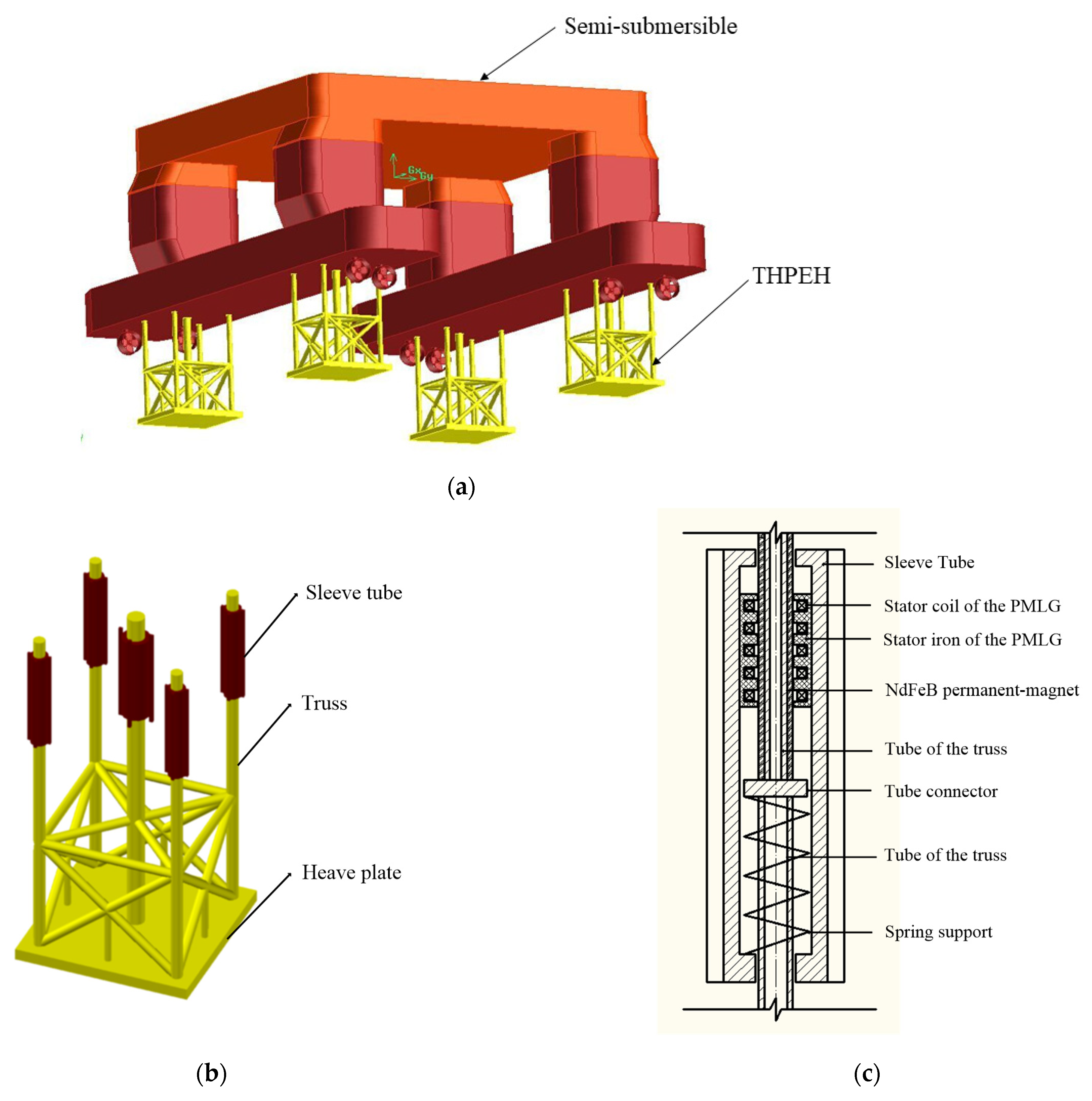
2.1. Conceptual Design of the Tuned Heave Plate Energy Harvesting System

The conceptual design of the semi-submersible platform with the THPEH is given in Figure 1a. Four tuned heave plates also can be considered as a multi-TMD system, and they offer a control moment for the platform to achieve anti-roll or anti-pitch control. Different from the conventional heave plate system, the heave plates of THPEH are connected to the platform by spring supports and power take-off systems. In this way, the relative motion between the plates and platform could drive the PTO system, and the THPEH can act as a tuned mass damper for the platform.
Figure 1b shows an illustration of a truss–plate structure of the THPEH. A permanent magnet linear generator (PMLG) is used and placed on the top of the truss tube in the platform pontoon. Figure 1c illustrates the structure of the sleeve tube. The connection only allows the heave plate to move along the vertical truss tube. The stator coil and iron are rigidly connected to the outer tube on the heave plate, and the tube wrapped by the permanent magnets extended from the truss structure can move through the stator and the outer tube on the plate. The PMLG could harvest the related motion energy to produce electrical power. A spring support is placed between the truss tube and the heave plate, which determines the natural period of the THPEH. However, besides the electrical generator’s damping, the main damping of the heave plate is the drag viscous damping from the fluid. Therefore, it is necessary to investigate the performance of the single tuned heave plate to verify the feasibility of the concept design.
In this paper, a THPEH is designed for a semi-submersible platform operated in the South China Sea. The key parameters of the platform and the THPEH are shown in Table 1.

2.2. Mathematical Model of the Tuned Heave Plate System

As shown in Figure 1c, the control force provided by each THPEH for the platform can be obtained as
F i = C G x ˙ rel , i K G x rel , i   i = 1 ,   2 ,   3 ,   4
where F i is the control force of the ith THPEH; x ˙ rel , i and x rel , i are the relative velocity and motion, respectively, between the ith THPEH and the platform; K G is the stiffness coefficient of the power take-off system; and C G is the damping coefficient of the generator. Once four THPEHs are installed in the semi-submersible platform, the total control force F con of the four THPEHs on six-degree-of-freedom (6-DOF) motion of the platform becomes [26]
F con = H [ F 1 F 2 F 3 F 4 ] T ,   H = [ 0 0 1 l y , 1 l x , 1 0 0 0 1 l y , 2 l x , 2 0 0 0 1 l y , 3 l x , 3 0 0 0 1 l y , 4 l x , 4 0 ] T
where l x , i , l y , i are the location coordinates of the ith THPEH in the horizontal plane. For Equation (2), it can be seen that the THPEH will provide the control force/moments to suppress the vertical plane motions as heave, roll, and pitch.
As the viscous effect of the heave plate is non-negligible, the Morison equation was adopted to describe the hydrodynamic force of the heave plate [13]:
F ( t ) = ρ C a x ¨ ( t ) + 1 2 ρ A C d | x ˙ ( t ) | x ˙ ( t )
where C a is the added mass coefficient, C d is the drag coefficient, is the equivalent volume of water displaced, = A L , L and A are the plate width and project area of the plate, and ρ is the density of water. The plate hydrodynamic parameters C a and C d are related with the motion amplitude and frequency. The non-dimensional Keulegan–Carpenter number (KC) represents the dimensionless motion amplitude, defined as [13]
K C = 2 π a L
where a is the amplitude and frequency of the oscillation. The hydrodynamic parameters C a and C d could be obtained by regressing the F ( t ) of the experiment by the least squares fitting method according to Equation (3).
The mechanism model for a single tuned heave plate could be simplified as a mass–spring–damper system. The PTO system is assumed to be combined with linear damping and stiffness forces, defined as
F PTO = C G x ˙ rel + K G x rel
Assuming that the gravity of the heave plate is equal to the buoyancy force of the plate, the motion of the tuned heave plate is governed by
ρ C a x ¨ ( t ) + ( C G + 1 2 ρ A C d | x ˙ ( t ) | ) x ˙ ( t ) + K G x ( t ) = C G x ˙ m ( t ) + K G x m ( t )
where x ¨ , x ˙ , and x are the acceleration, velocity, and displacement, respectively, of the tuned heave plate in heave motion; x ˙ m and x m are the velocity and displacement, respectively, of the platform. The damping of this tuned heave plate system is contributed by the hydrodynamic force of the plate and the generator. The damping ratios contributed by these two parts are defined as
ξ H = C H 2 m a ω n = 1 / 2 ρ A C d a ω 2 ρ A L C a ω n = K C 8 π · C d C a · ω ω n
ξ G = C G 2 m a ω n
where ξ H and ξ G are the damping ratios contributed by the hydrodynamic force of the plate and the generator, respectively; ω is the frequency of the platform motion; and ω n is the tuned frequency of the tuned heave plate, given by
ω n = K G m a
The motion of the heave plate could be amplified when the natural frequency of the tuned heave plate is tuned to the motion frequency of the platform. The dynamic amplification factor (DAF) of the heave plate is given by
D A F = a p a m
where a p and a m are the amplitudes of the heave plate motion and platform motion, respectively.
According to the hydrodynamic forces of the conventional heave plate, the equivalent added mass coefficient E a and the equivalent damping coefficient E d are proposed to describe the effect of the tuned heave plate on the platform heave motion. The equivalent E a and E d could be obtained by regressing the experimental F PTO values by the least squares fitting method according to
F PTO = ρ E a x ¨ m + 1 2 ρ A E d x ˙ m | x ˙ m |
The energy absorbed by the tuned heave plate system from the platform motion is dissipated in water and captured by the PTO system. The consumed power P t and captured power P c of the tuned heave plate are defined as
P t = 0 T F PTO · x ˙ m d t / T
P c = 0 T F PTO · x ˙ rel d t / T
where P t represents the energy consumption of the platform motion by the plate system, and P c represents the captured energy of the PTO system. In order to compare with the conventional fixed heave plate, the consumed power of the fixed heave plate P f is also defined as
P f = 0 T F ( t ) · x ˙ m d t / T
where F ( t ) is the hydrodynamic force of the fixed heave plate with platform motion velocity x ˙ m , representing the energy consumption of the platform motion by the fixed heave plate. The ratio λ c between P c and P t indicates the energy harvesting efficiency from the consumed power. λ c is given by
λ c = P c / P t

3. Experiments

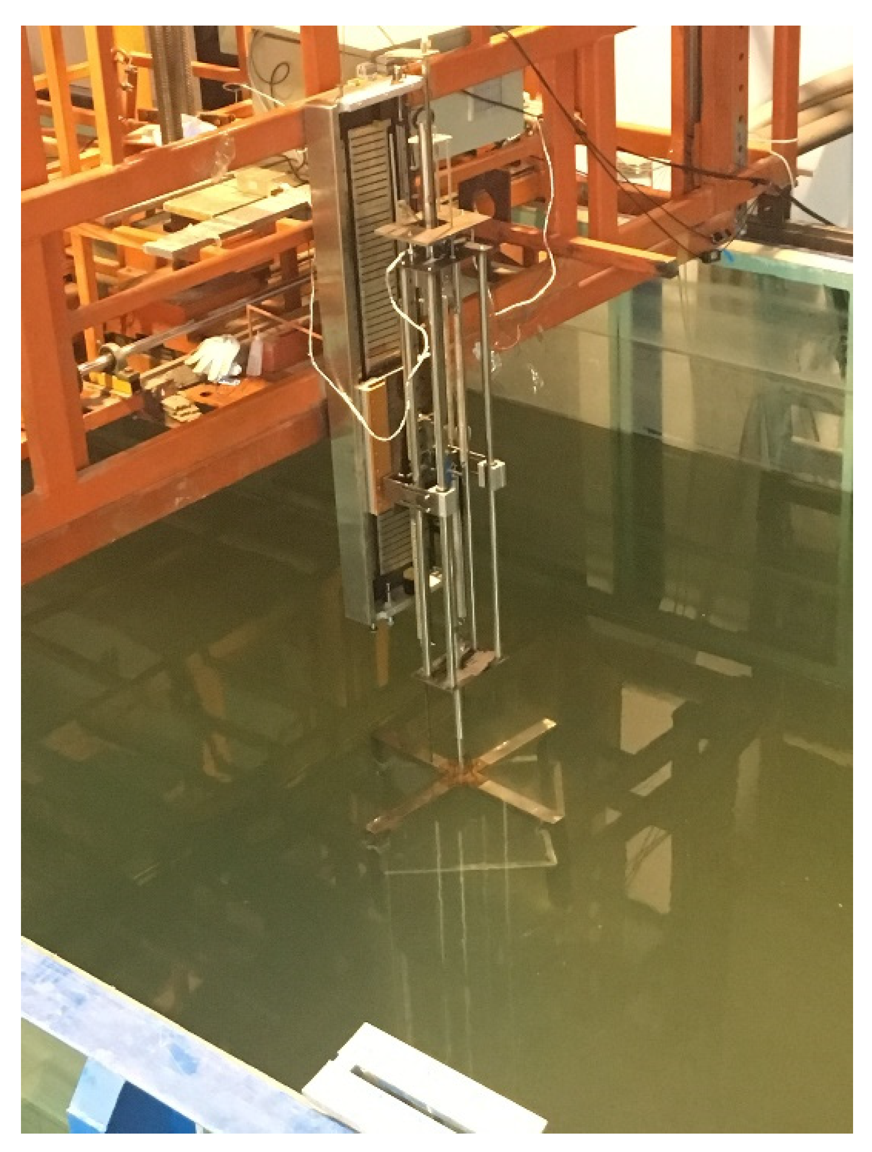
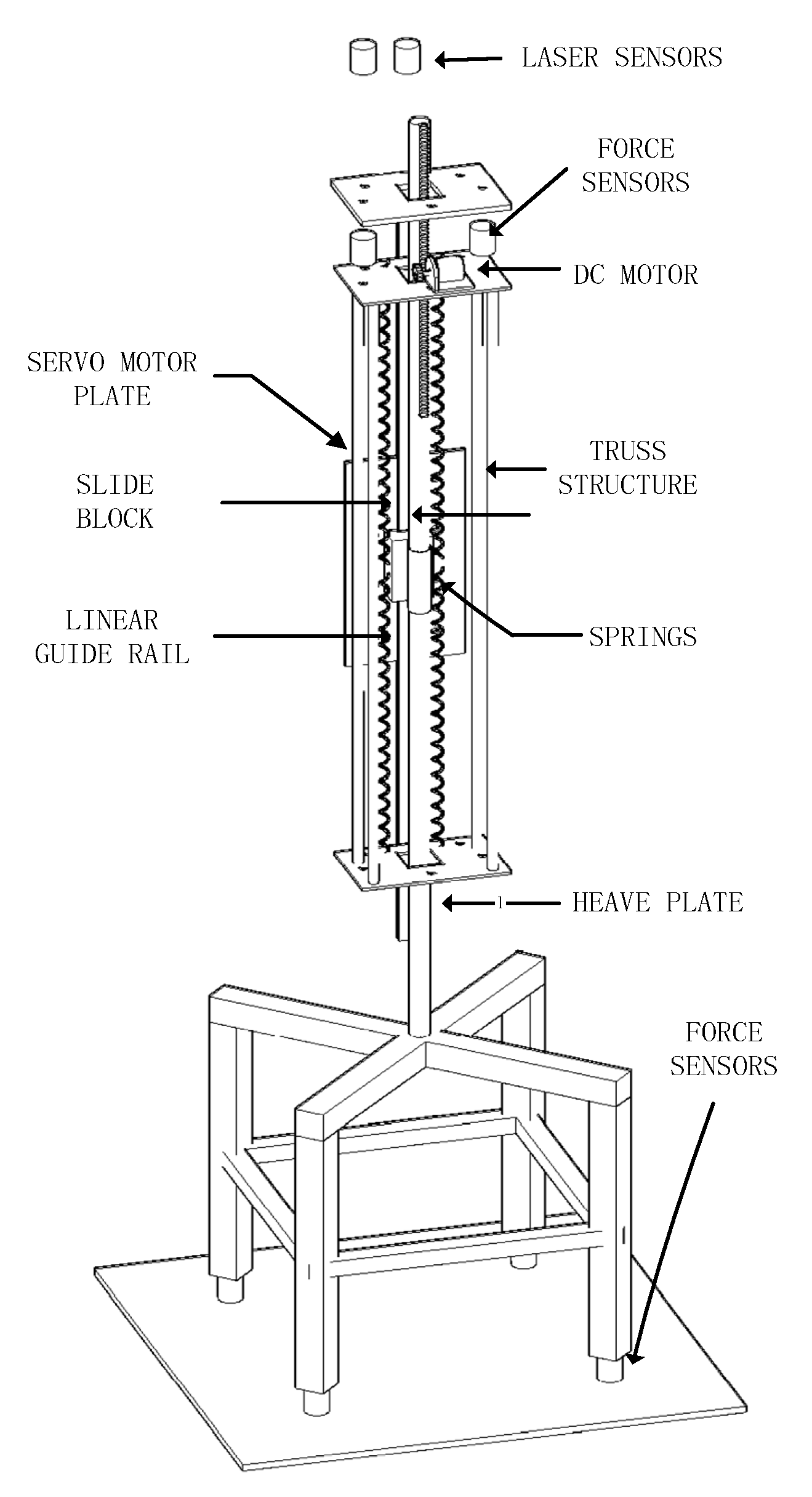
3.1. Setup of the Heave Plate Experiment

In order to investigate the control performance of the THPEH, one tuned heave plate of the THPEH was arranged for a forced oscillation test. Because the scale of the physical model was 1:20, a square solid plate made of 20 mm thick acrylic with a length of 850 mm was adopted. The experiments were performed in the Nonlinear Wave Flume at the State Key Laboratory of Coastal and Offshore Engineering of Dalian University of Technology. The wave flume was 60.0 m long and 4.0 m wide, and the maximum water depth was 2.5 m. The test model was in the middle of the flume to minimize the effects of the flume wall. Figure 2 shows a picture of the experimental model in the wave flume.
A schematic of the experimental setup is shown in Figure 3. The exciting motion of the THPEH was driven by a servo linear motor. The motor’s motion was adopted to simulate the vertical motion of the platform. A linear guide rail and slide block were used to make sure that the plate could only oscillate in the vertical direction. A truss structure was used to employ springs and a generator between the plate and the servo linear motor. Four waterproof force sensors were mounted between the truss and the plate to monitor the hydrodynamic forces of the heave plate, and two force sensors were mounted between the truss and the motor to monitor the control force of the THPEH on the excitation motion. Four tension springs and a motor were used to contribute the stiffness and damping, respectively, of the PTO system. The submergence of the plate was set to 1 m below the water level. In addition, two laser displacement sensors were installed at the top of the system to record the displacements of the plate and the servomotor’s excitation motion.
The tests were designed to investigate the control forces, the harvesting energy of THPEH with different tuned periods, and the PTO damping levels under exciting motions with different periods. Two tests were conducted separately.
The first test was the hydrodynamic performance test of the fixed heave plate. The hydrodynamic parameters were obtained in this test. The control force of the fixed heave plate on the exciting motion was also monitored. In this test, the guide rail sliding block was locked, and the plate was forced to oscillate following the given displacements.
The other test was the performance test of the THPEH. Three tuned periods of 1.79 s, 2.24 s, and 4.25 s, marked as THP1, THP2, and THP3, were studied; these refer to 8.0 s, 10.0 s, and 19 s for the prototype. The test parameters of the THPEH are shown in Table 2. The springs for the tuned heave plate were selected based on the results for hydrodynamic coefficients and the tuned periods, according to Equation (7). A DC gear motor with internal resistance R I = 5   Ω was adopted as the PTO system for the THPEH. Seven load resistances R L of 0   Ω , 2   Ω , 5   Ω , 10   Ω , 20   Ω , 30   Ω , and Ω were adopted to adjust the damping level of the PTO system, where R L = Ω indicates that the circuit was open. For each work condition, 15 periods covering the whole period range with amplitude 40 mm (KC = 0.3) were tested.
In all the tests, the sampling frequency of the data acquisition system was set to 100 HZ, and a low-pass filter with cut-off frequency 10 HZ was adapted for the force sensor signals.

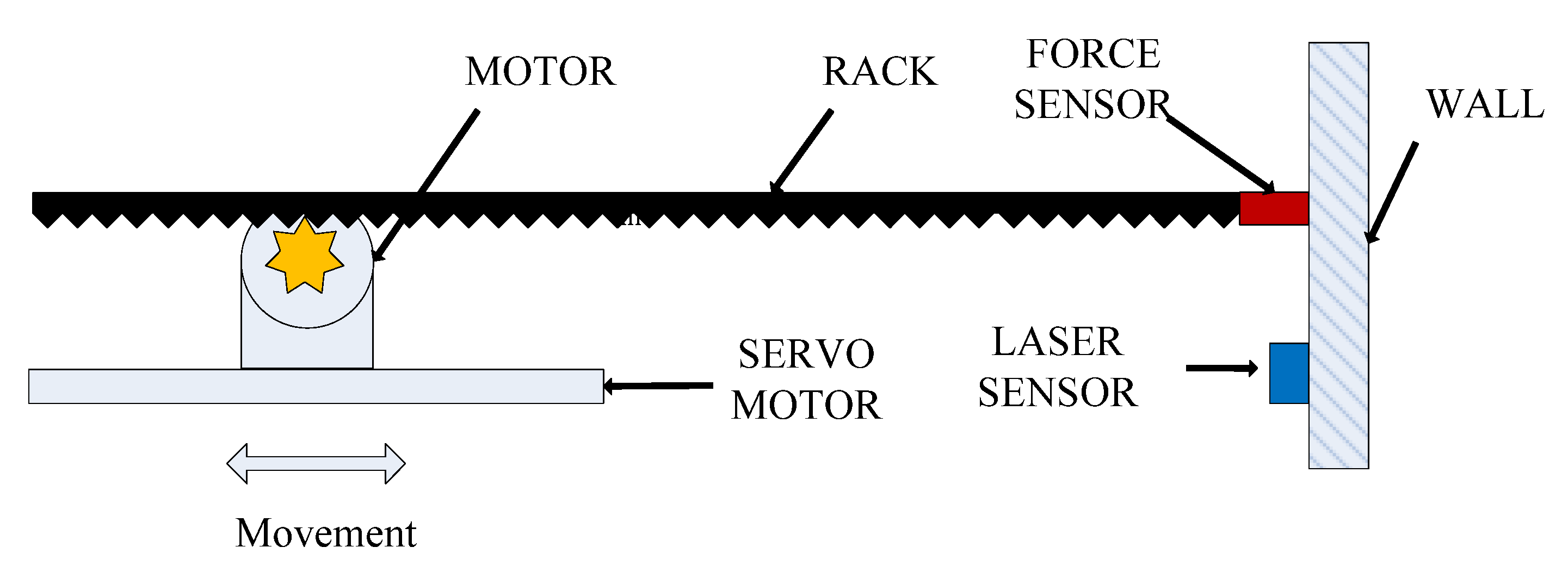
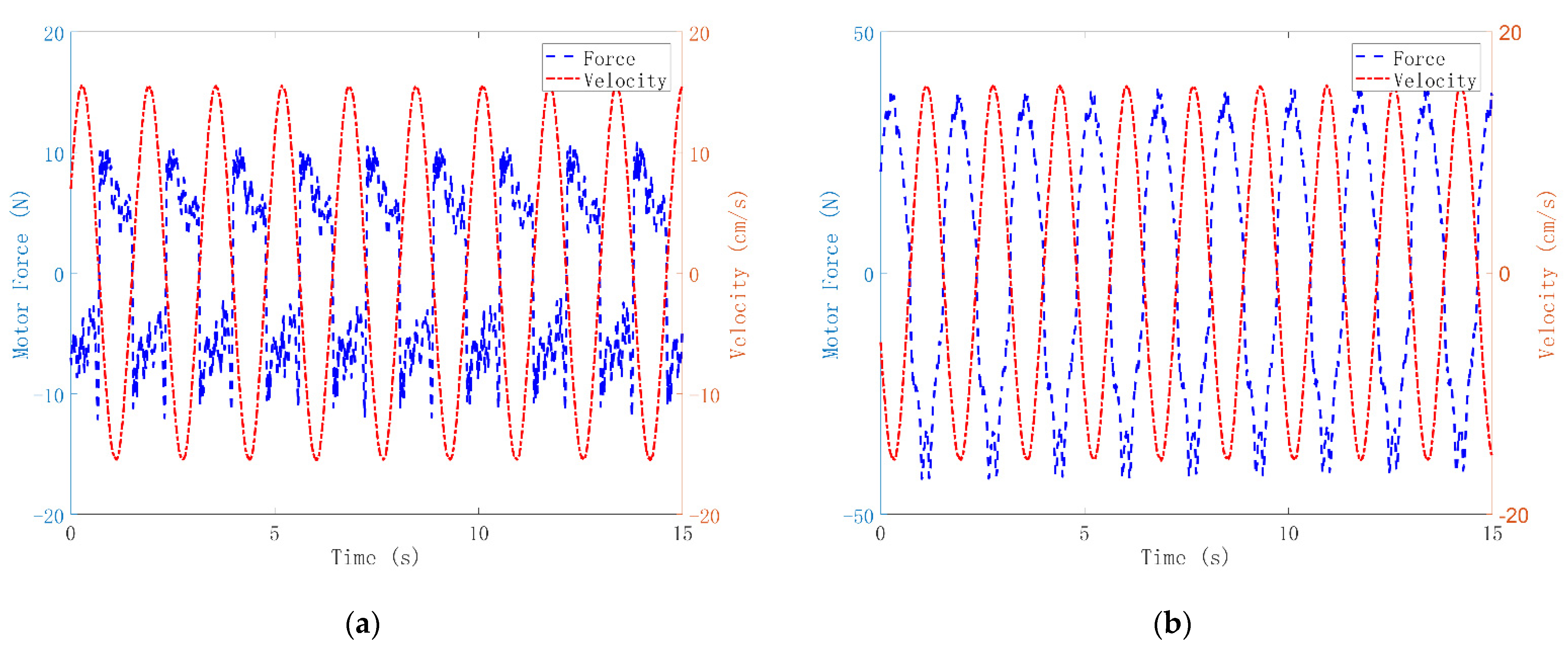
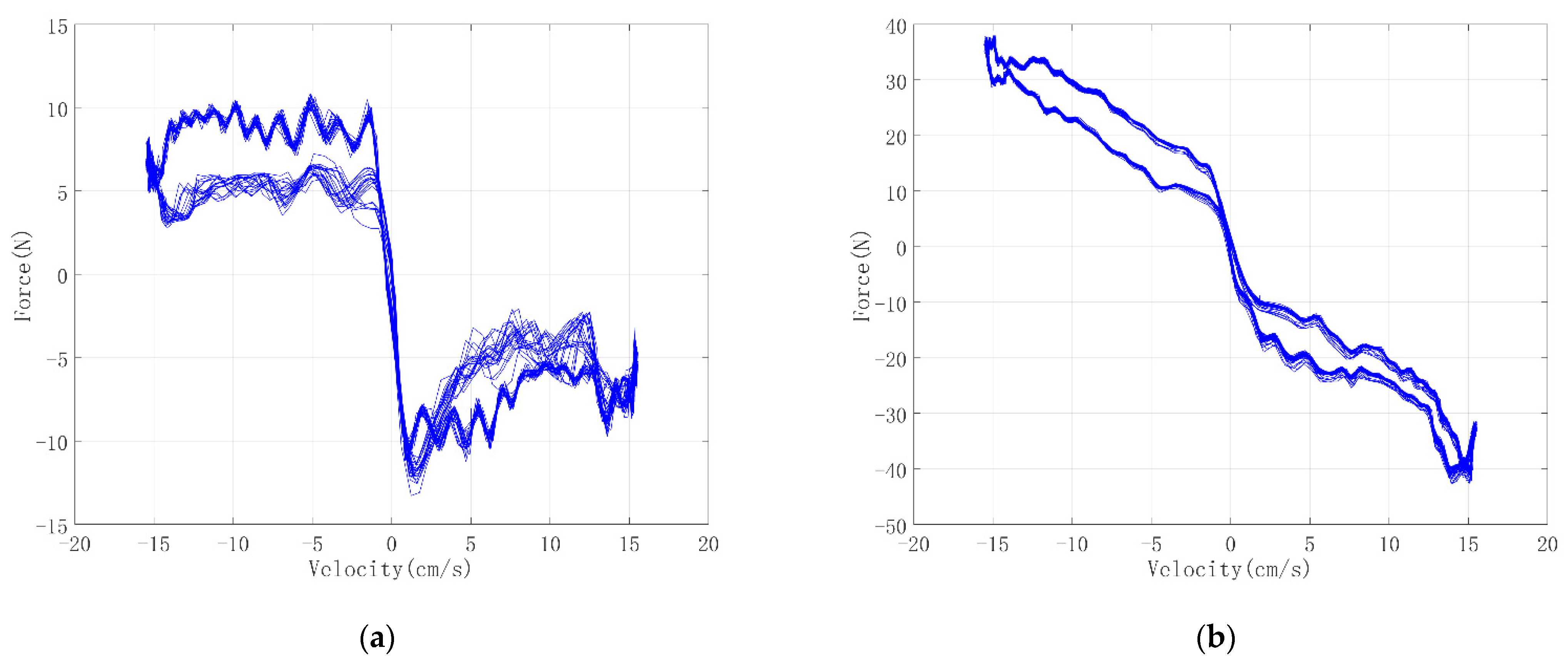
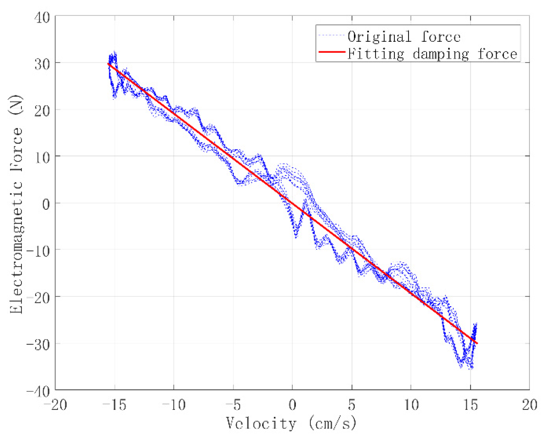
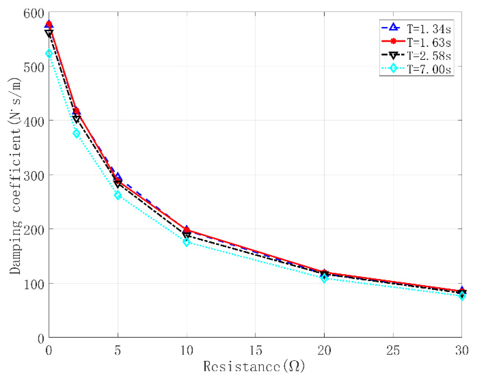
3.2. Setup of the Force Calibration Test of the PTO System

As the force of the PTO system is difficult to monitor, a calibration test of the motor force was arranged. Theoretically, the induction electromagnetic force of the motor is a linear damping force for the drive movement. However, because of the motor reducer and the friction force between the pinion and rack, the force of the PTO system is complicated. Therefore, a calibration test was carried out to identify the force model of the DC gear motor used in the heave plate experiment; the arrangement of the test is illustrated in Figure 4. The gear motor was rigidly connected to the servomotor, and the rack was connected to a wall by a tension sensor; a laser displacement sensor was placed on the wall to monitor the movement of the actuator. The periods for this test ranged from 1.34 s to 7 s with amplitude 40 mm. For each condition, seven load resistances, ranging from 0   Ω to Ω , were tested.
Figure 5 shows the time history curves of the filtered motor forces and input velocities under excitation movement with amplitude 40 mm and period 1.63 s for R L = 10   Ω and R L = Ω . Figure 6 shows the traces of the motor forces against input velocity under these conditions. According to Figure 6a, the force of the motor is similar to a friction force with R L = Ω . The motor forces under R L = 10   Ω shown in Figure 6b indicate that the motor force is a combination of friction force and damping force. While under the same motion excitation, the frictional force and the inertial force of this system should be the same at the same load moment, even with different load resistance. Under this assumption, the electromagnetic force of the motor could be estimated by subtracting the force under R L = Ω from the measuring force. Figure 7 shows the trace of the electromagnetic force and the damping force against input velocity with R L = 10   Ω , and the regression under the excitation movement. Therefore, the resistance force model could be described as
F m = C e v s i g n ( v ) F f = C m R L + R I v s i g n ( v ) F f
where F m , C e , v , F f , and C m are the motor force, the linear damping coefficient of the motor, the drive speed of the servomotor, the friction force, and an undetermined constant value of the motor, respectively. F f and C m could be obtained by regressing the experimental F m values via the least squares fitting method according to Equation (16). The relationships between the load resistance and the linear damping coefficient under each excitation condition are shown in Figure 8. The average identified values of F f and C m are
F ¯ f = 8.41 N , C ¯ m = 2871 N · s · Ω / m
For simplicity, the following coefficient is introduced to calculate the frictional force:
C e q = 4 F ¯ f ω π a
where C e q is the equivalent damping coefficient of the frictional force F ¯ f . ω and a are the frequency and amplitude of the movement, respectively. The total damping coefficient contributed by the generator could then be presented as
C G = 4 F ¯ f ω π a + 2871 R L + R I

4. Results and Discussion

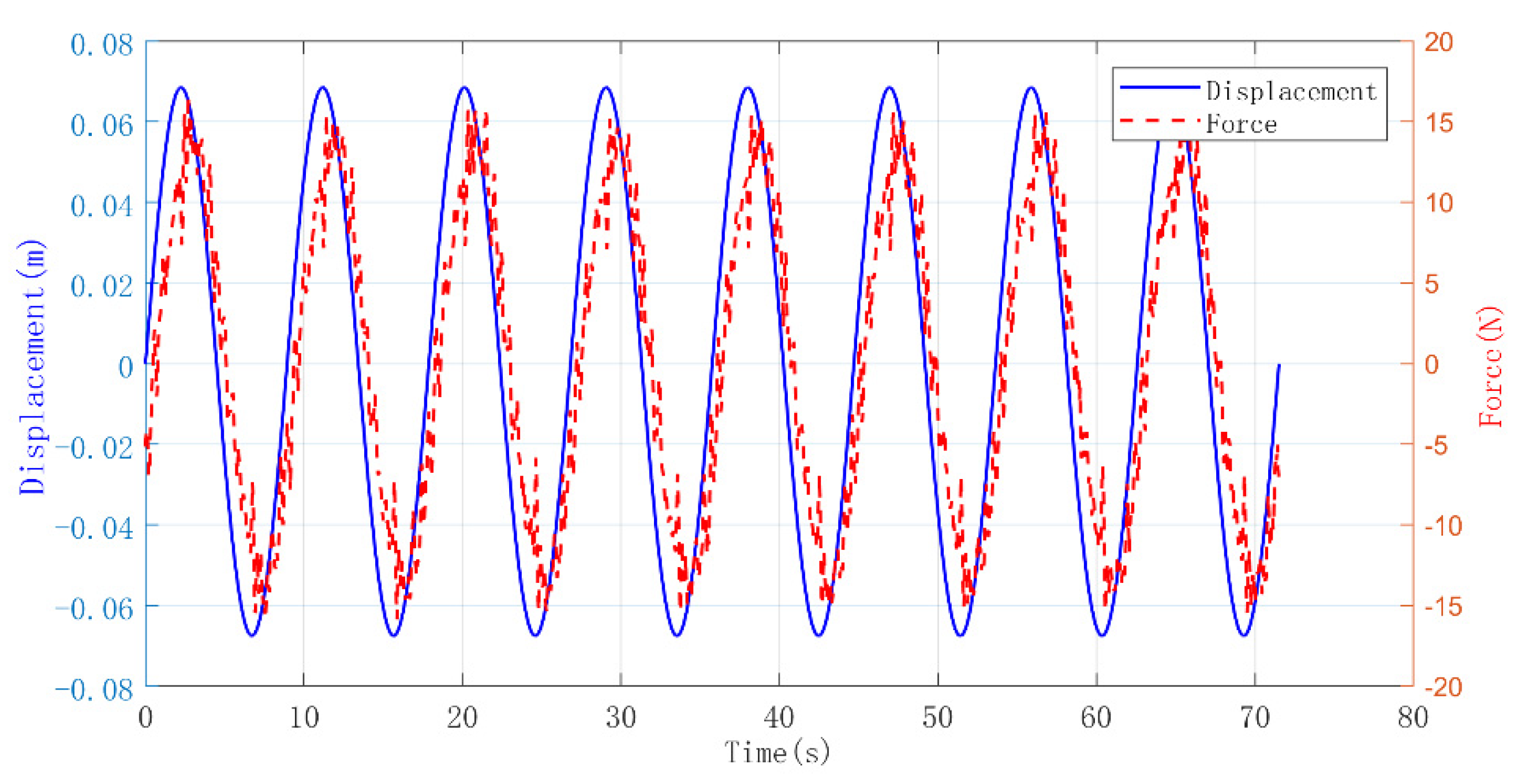
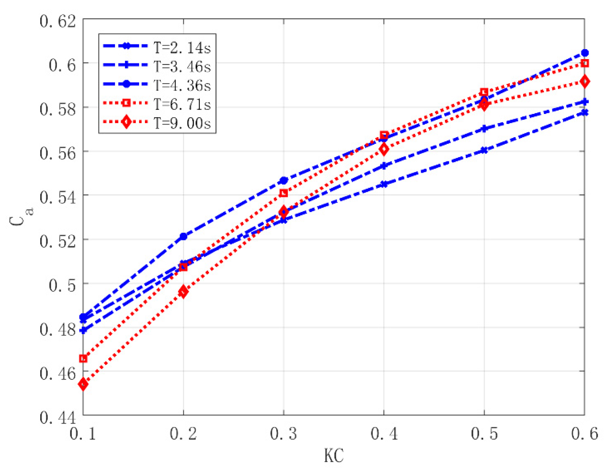
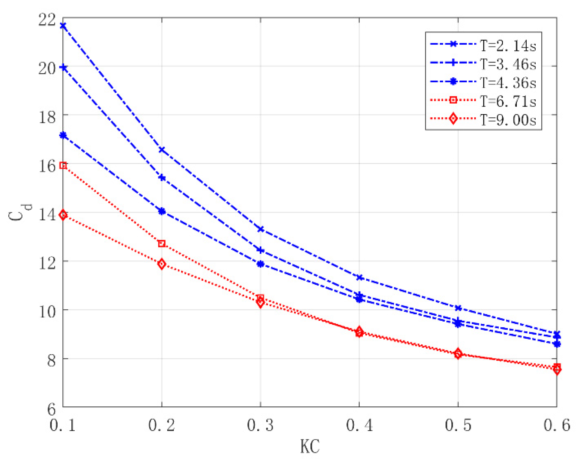
4.1. Hydrodynamic Analysis of the Heave Plate

Many experimental studies on the hydrodynamics of square heave plates have been carried out; however, due to the different ranges of parameters and conditions, their conclusions were not totally consistent. Therefore, hydrodynamic analysis of the heave plate was carried out before investigations of the THPEH. The control force of the fixed heave plate could serve as a contrast with the control force of the THPEH.
In this test, the heave plate was set to 1.0 m below the water level, and the water depth was 2.5 m. Exciting motions with five excitation periods ranging from 2.14 s to 9 s and six KC numbers ranging from 0.1 to 0.6 were tested. These test parameters cover the range of heave motions of a typical semi-submersible platform according to the geometric scale of 1:20.
Figure 9 shows a typical record of the measured hydrodynamic force and the heave displacement of the heave plate. According to Equation (3), the added mass coefficient C a and drag coefficient C d with different motion periods and KC numbers could be identified by the least squares method. The identified hydrodynamic parameters are shown in Figure 10 and Figure 11.
The results show that the added mass coefficient C a increased with the KC number in a generally linear relationship. In contrast, the drag coefficient C d of the heave plate decreased with increasing KC number. The results are consistent with the literature [12,27]. Figure 10 shows that the frequency had little effect on the added mass coefficient. However, the drag force coefficient increased with increasing motion frequency, as shown in Figure 11. These results are identical to Tao’s results [28].

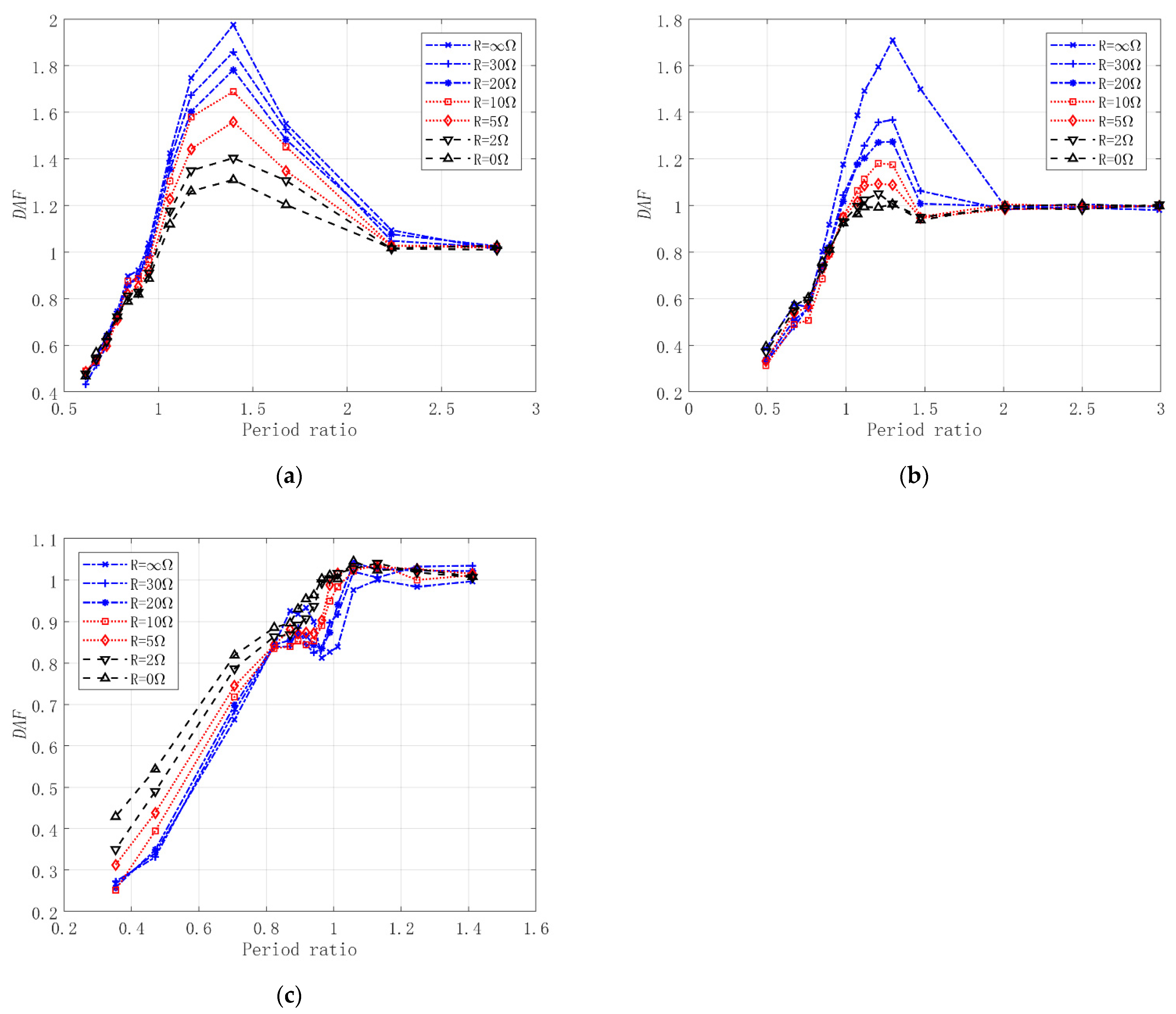
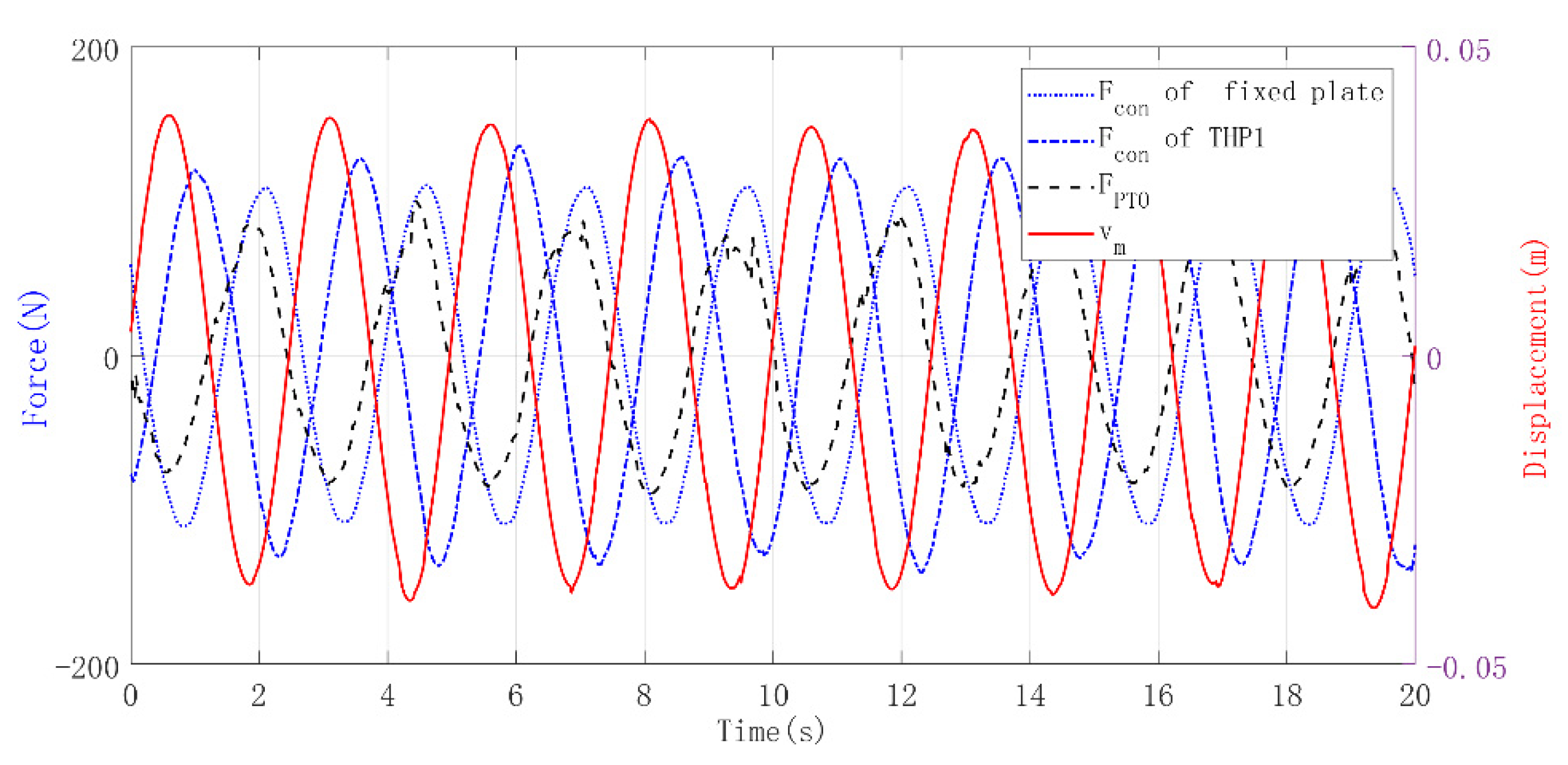
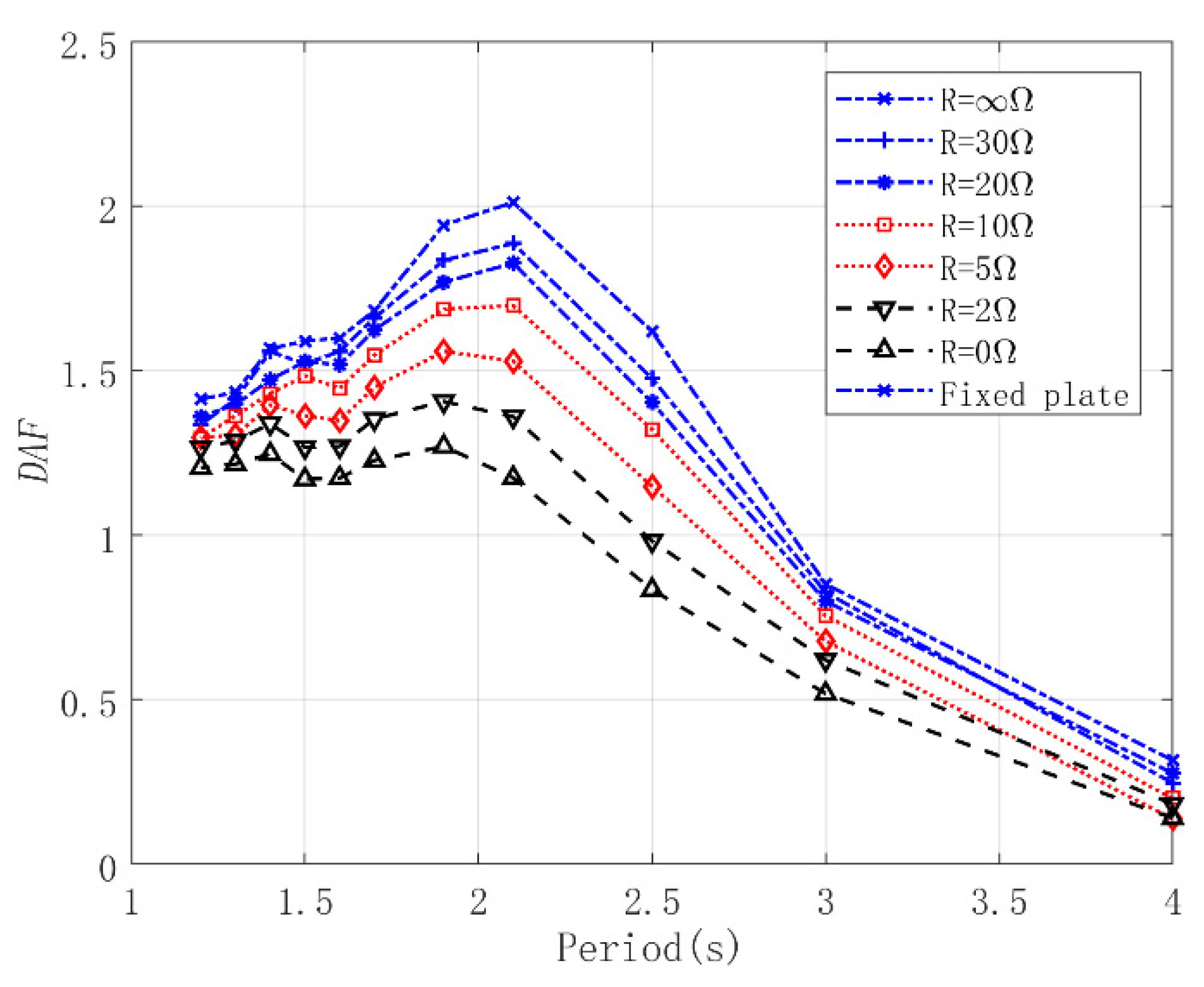
4.2. Control Performance of the THPEH

The control performance of the THPEH on the motion of the platform could only be evaluated indirectly, as only the THPEH was tested. In this case, two aspects of performance are discussed to evaluate the control performance of the THPEH: the motion and the force of the THPEH.
Firstly, the motion performance of the THPEH with different tuned periods is discussed. Similar to that of the conventional TMDs, the motion of the heave plate needs to be excited to magnify the control force on the platform. However, unlike for conventional TMDs, for the THPEH, the damping of the tuned heave plate system is contributed by two parts—hydrodynamic damping and motor damping—and the mass of the THPEH is also contributed by two parts—the mass and the added mass. These may bring differences when compared to conventional TMDs. Figure 12 displays a typical time history record of the servomotor displacement, heave plate displacement, and measured control force. The amplitude of the heave plate is much larger than the exciting motion, which could generator larger control force on the platform. Figure 13 shows the DAF of the tuned heave plate system with different tuned periods and the load resistances under different motion excitations. The results show that the motion of the THP 1 and THP 2 systems is excited near its natural period, and the DAF values are larger than 1. Due to the damping contributed by the generator and hydrodynamic force, the resonant period is shifted from the tuned period. However, the motion of THP 3 was not excited within the whole period range. This may be due to the large damping ratio of THP3.
The damping ratio of the THPEH could affect the motion performance of the plate. According to Equations (5), (6) and (16), the damping ratios of the different THPEHs at resonant periods are shown in Figure 14. The hydrodynamic parameters of the THPs were obtained by spline interpolation according to the KC number and resonated periods for each THP with different load resistances. Under KC = 0.3, when the amplitude of the excitation motion was 40 mm, the damping ratio contributed by the hydrodynamic force was about ξ H = 24.7 % , and the motor could bring up to a 28%~66% damping ratio due to different tuned periods and load resistances. For THP3, the total damping ratio was 54~102% within the period range, which means that the motion of THP3 could not be excited.
Secondly, in order to compare with the fixed heave plate system, the equivalent hydrodynamic parameters of the THPEH are introduced to describe the control force of the THPEH. The equivalent hydrodynamic parameters can be obtained according to Equation (9) from the control force of the THPEH. Like the hydrodynamic coefficients of the conventional fixed heave plate, the equivalent hydrodynamic parameters represent the added mass and viscous damping of the control force on the excitation motion with different periods. The respective equivalent hydrodynamic parameters of the three THPEHs are shown in Figure 15, Figure 16 and Figure 17. For THP1 and THP2, as the motion was excited near the tuned period, the damping coefficients are much larger than those for the fixed heave plate. However, the equivalent added mass coefficient is smaller than that for the fixed heave plate. For THP3, as the motion was not excited, the equivalent added mass and damping coefficients are smaller than those for the fixed heave plate. The conventional fixed heave plate provides large added mass and viscous damping to reduce the platform motion. However, as a well-designed platform, its natural period has already been set away from the wave period range. In this case, additional damping plays a more important role in motion suppression than the added mass. This indicates that the THPEH could offer greater damping to the platform as long as the motion of the heave plate is excited.
The heave motion of the platform consists of wave frequency motion and natural frequency motion under a real sea state. According to the results, the THPEH should be tuned to the wave frequency to ensure that the motion of the THPEH can be excited. For low-natural-frequency motion, the control performance of the THPEH tuned to the wave frequency is still no worse than that of the conventional fixed heave plate.

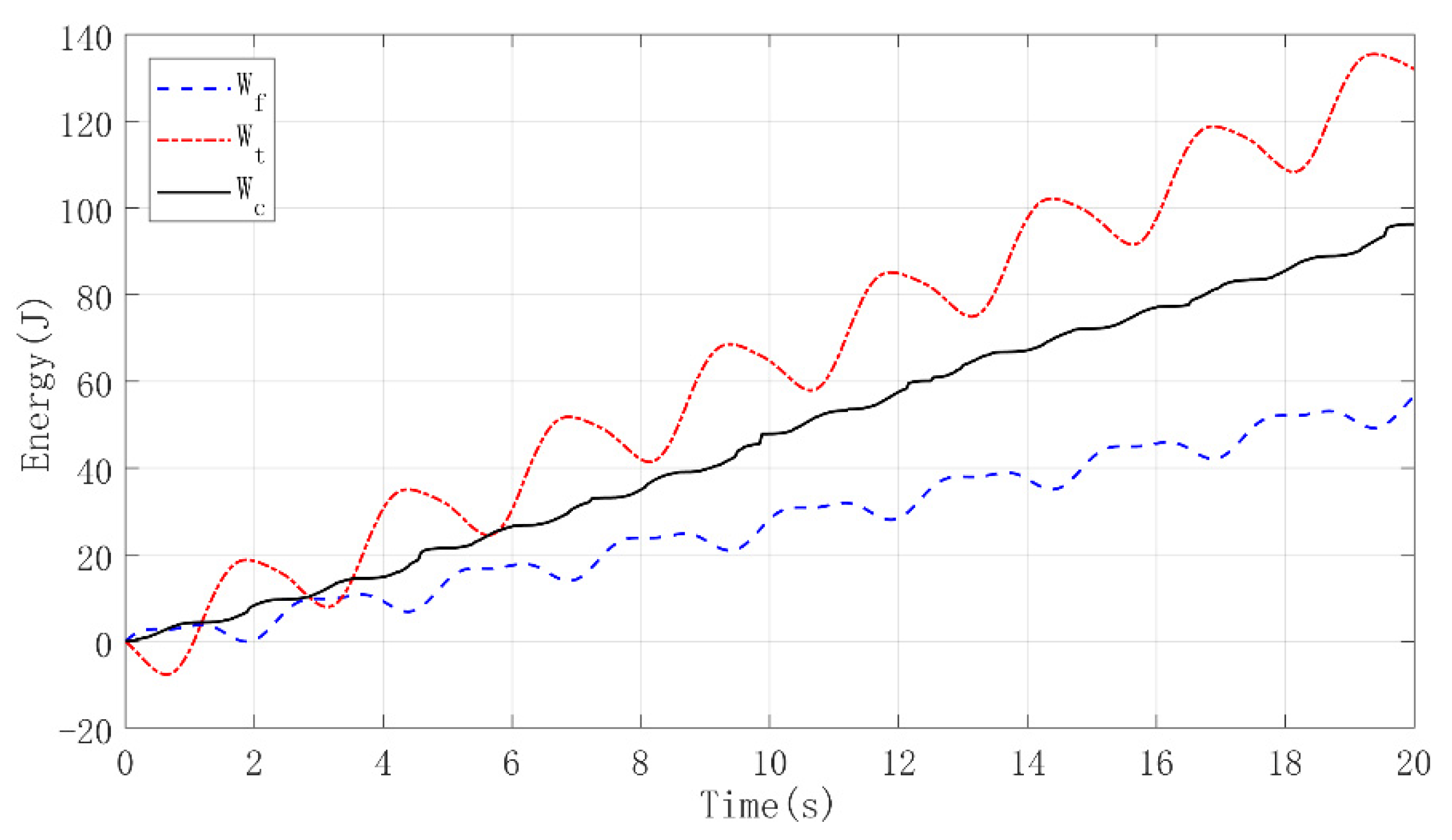
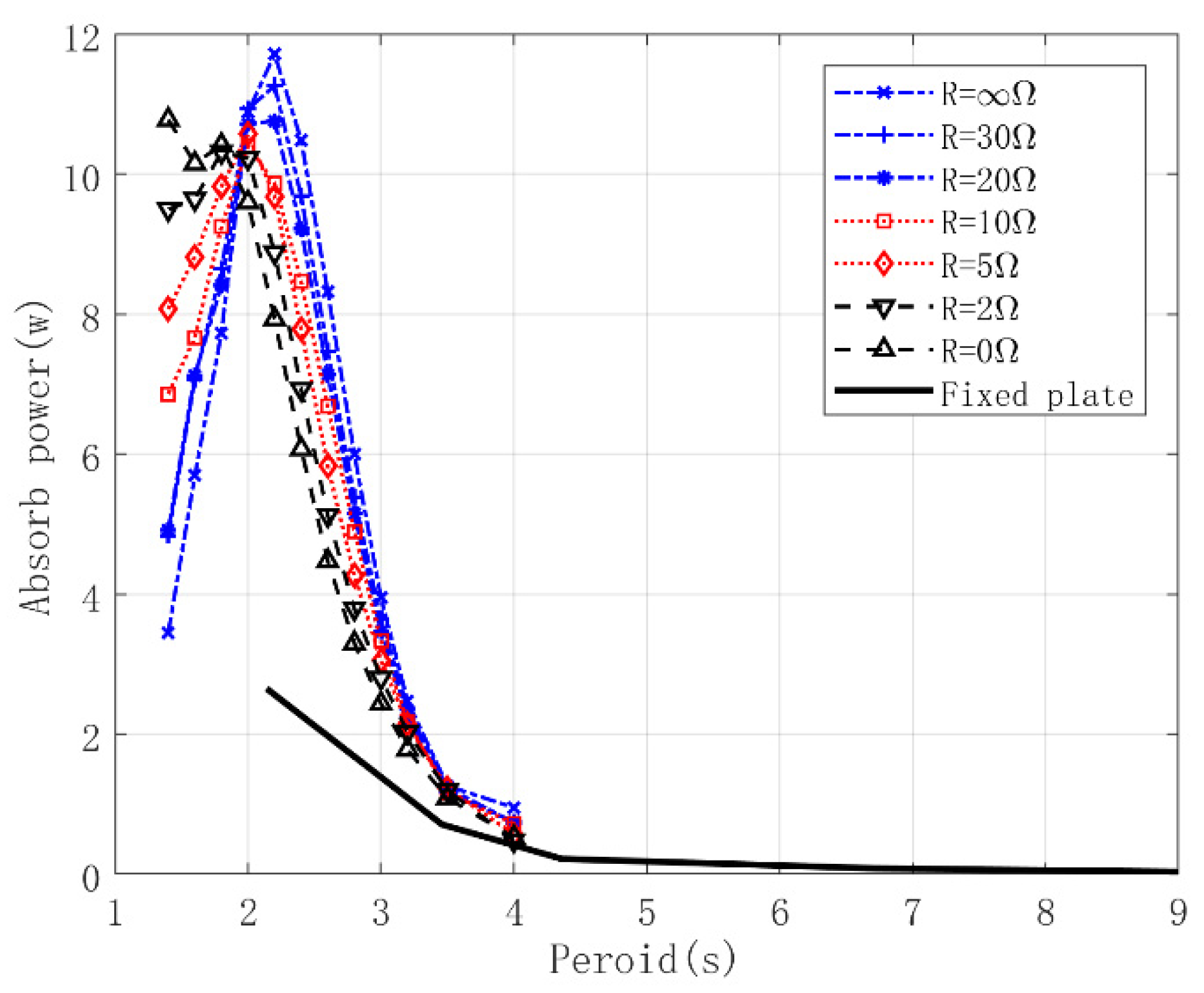
4.3. Energy Analysis of the THPEH

In order to further find the control mechanism of the THPEH, the energy flows of the THPEH were analyzed. Figure 18 shows the time series of the control force and PTO force of THP1 and the fixed heave plate system under excitation motion with period 2.5 s and KC = 0.3. The motor force was calculated according to the motor force model and the measured relative motion of the tuned heave plate. According to Equations (10)–(12), the consumed work of THP1, the captured work of the PTO, and the consumed work of the fixed heave plate can be calculated, denoted W t , W c , and W f . Time series of the energies are shown in Figure 19. Under this condition, compared to the fixed heave plate, the THP1 system consumes 2.5 times the energy from the excitation motion due to the resonation, and most of the consumed energy is captured by the PTO system.
The power consumed by THP1 with different LRs under different excitation periods is shown in Figure 20. For different LRs, the absorbed power reaches its maximum value as the excitation period approaches the natural period of the THP1. The absorption power decreases with increment of the LR value in general. The absorption power could represent the control performance of the THPEH. Compared to the fixed heave plate, it indicates that the tuned heave plate system could absorb much more energy from the platform motion when the heave plate system is tuned to the heave motion period of the platform. This enhanced control performance is due to the dynamic amplified effect of the tuned heave plate system, which could bring greater damping force to the platform heave motion. With increment of the LR, the dynamic amplified effect decreases, which could reduce the control performance of the tuned heave plate system.
Figure 21 shows the power captured by the PTO system of the THPEH with different LRs under different period motions. It shows that the captured power of THP1 reaches its peak value when the motion period is near its natural period. The DAF of the relative motion between THP1 and the platform shows the same phenomenon in Figure 22. The power captured by the PTO system is incremented with the LR value. The captured energy ratio of THP1 with different tuned periods and LRs is shown in Figure 23. It indicates that the PTO system could capture up to 80% of the absorbed energy of the THPEH with optimal parameters.

5. Conclusions

This paper presents the results of experimental investigations into the performance of a tuned heave plate energy harvesting system (THPEH), employed on a semi-submersible platform to suppress the platform’s motions and harvest energy from the wave-induced response. The motion performance, control performance, and energy harvesting performance of the THPEH were systematically studied through forced oscillation model tests on a 1:20 scale model. The results show the following:
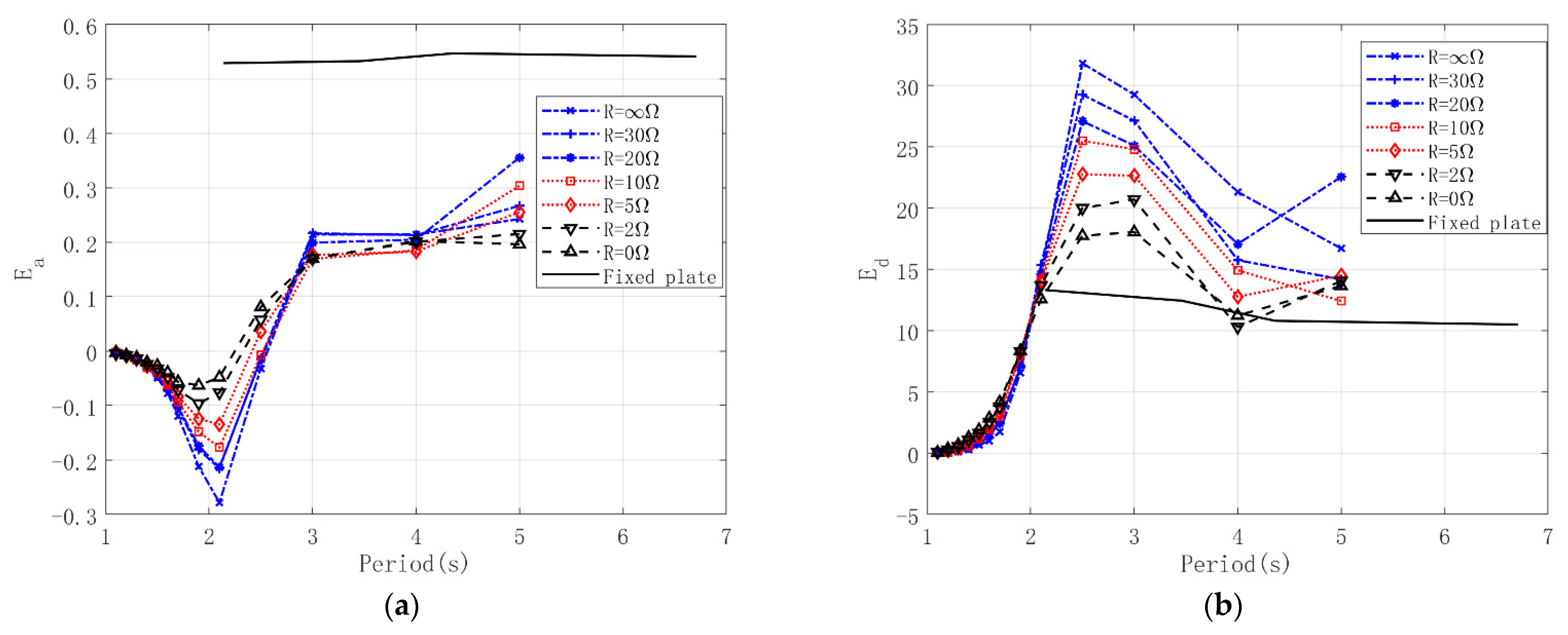
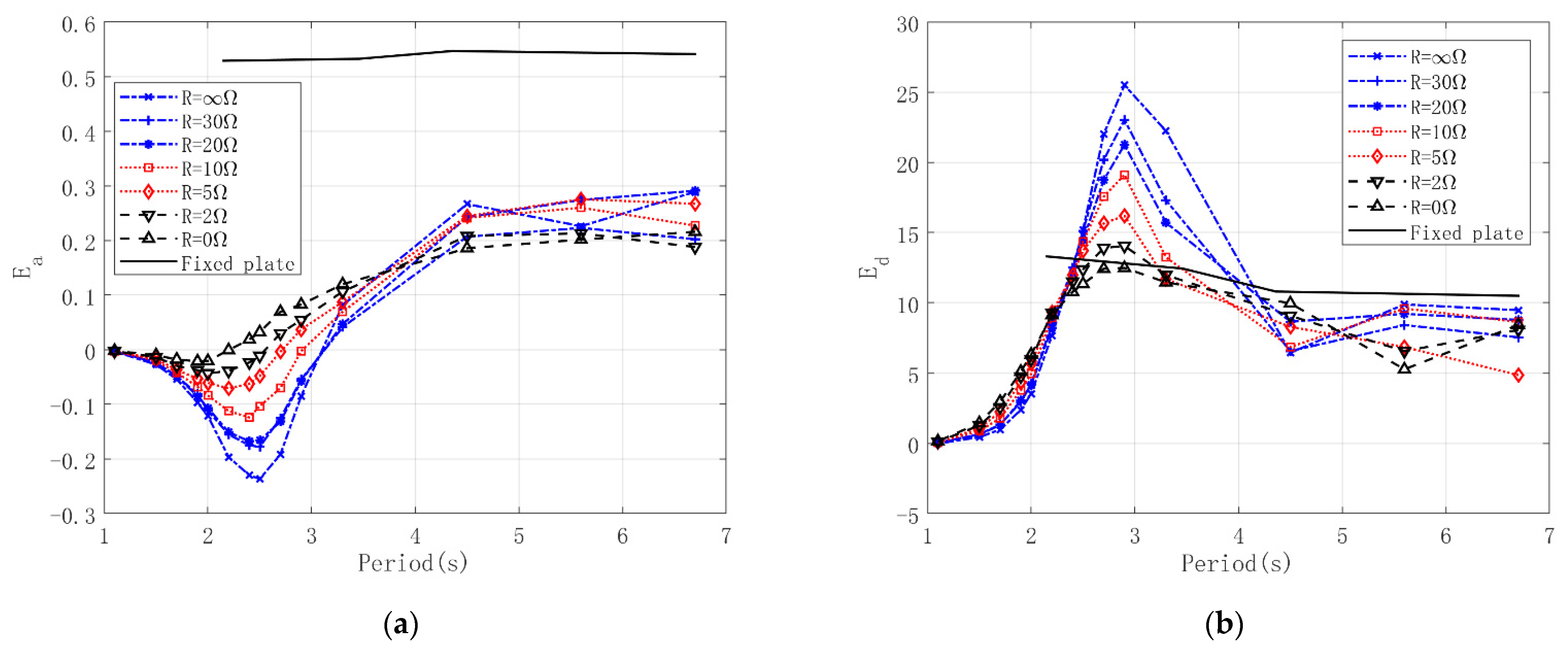
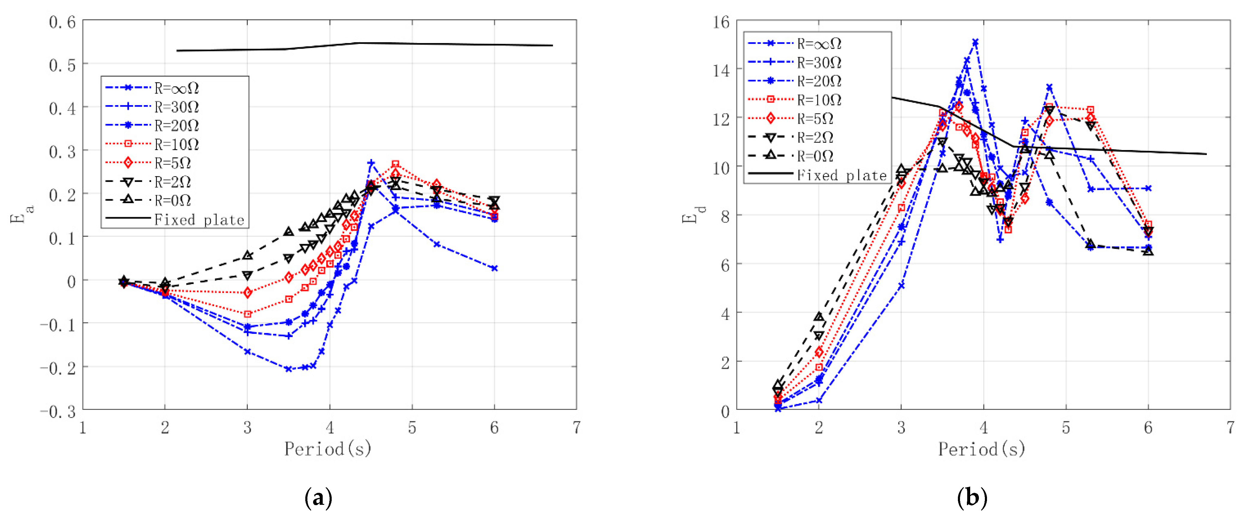
  • Compared to the fixed heave plate system, a well-tuned THPEH could consume more energy from the exciting motion, while providing larger damping force to the exciting motion. THP1 consumes up to 2.5 times the energy from the platform motion near the tuned period of the THPEH compared to the fixed heave plate.
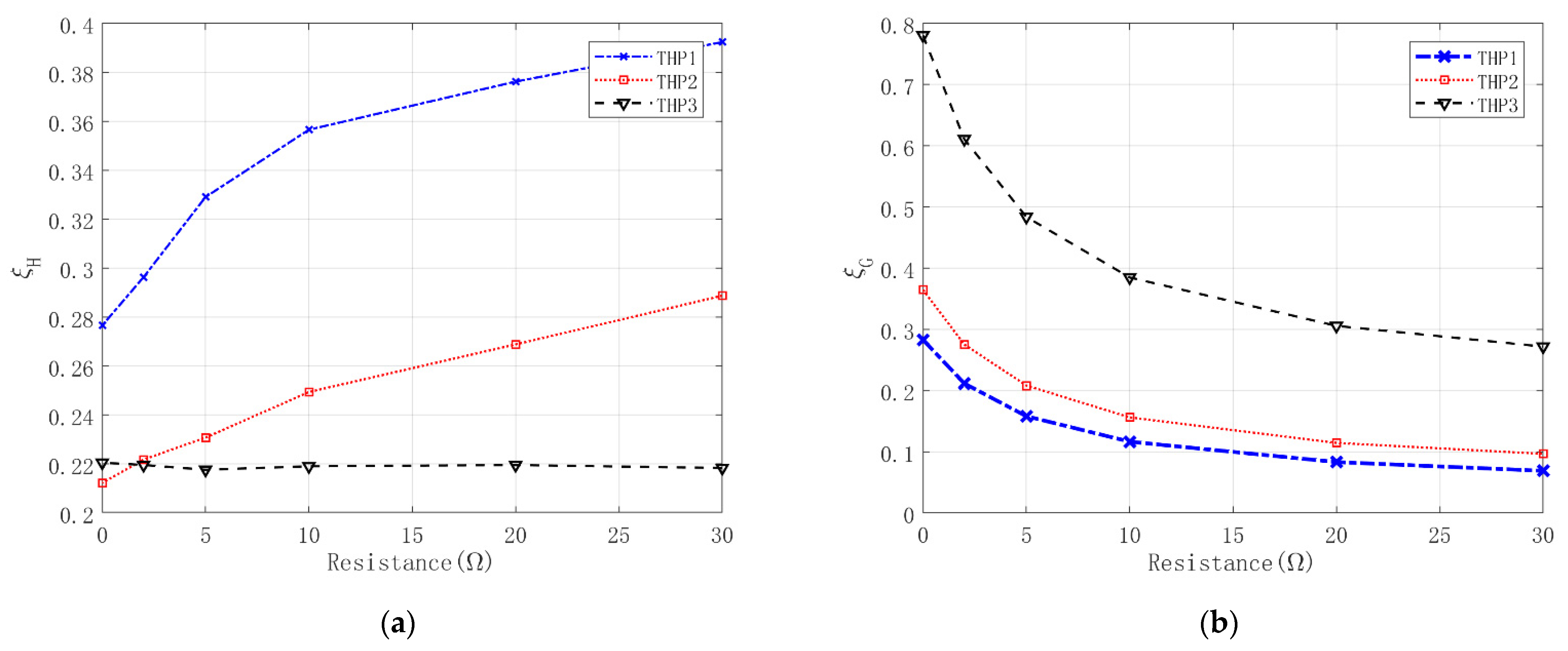
  • Different from conventional TMDs, the THPEH should be tuned to the wave frequency to ensure that the motion of the THPEH can be excited, due to the large damping ratio contributed by the damping force of the heave plate and PTO system.
  • The control performance of the THPEH decreases with increment of the PTO damping level, while the energy harvesting performance increases with the PTO damping level. For THP1, the PTO system could capture up to 80% of the energy absorbed by the system under optimal parameters.

Author Contributions

Conceptualization, K.L.; methodology, H.L.; software, H.L.; formal analysis, K.L.; investigation, K.L. and H.L.; writing—original draft preparation, K.L.; writing—review and editing, D.W.; supervision, J.O. and J.Y. All authors have read and agreed to the published version of the manuscript.

Funding

The study was supported by the National Natural Science Foundation of China (No: 51809096), Natural Science Foundation of Guangdong Province (No: 2021A1515012059), Applied Basic Research Project of Guangzhou (No: 202102020619), and Open Foundation of the State Key Laboratory of Ocean Engineering (No: 1711).

Institutional Review Board Statement

Not applicable.

Informed Consent Statement

Not applicable.

Data Availability Statement

Not applicable.

Acknowledgments

The authors would like to thank Ren Nianxin from Hainan University for his valuable discussion of the PTO system test.

Conflicts of Interest

The authors declare no conflict of interest.

Abbreviations

The following abbreviations are used in this manuscript:
λ c Ratio between captured power and consumed power
ξ H Damping ratio contributed by hydrodynamic force
ξ G Damping ratio contributed by PTO force
ρ Density of water
ω Frequency of platform motion
ω n Frequency of plate motion
Equivalent volume of water displaced by the plate
AProject area of the plate
a Amplitude of plate motion
a p Motion amplitude of the plate in heave
a m Motion amplitude of the platform in heave
C a Added mass coefficient of the plate
C d Drag coefficient of the plate
C e Linear damping coefficient of the motor
C e q Equivalent damping coefficient of frictional force
C G Total damping coefficient of the power take-off system
C m Constant value for the motor
C ¯ m Average identified value of C m
D A F Dynamic amplification factor of plate motion
E a Equivalent added mass coefficient of the THPEH
E d Equivalent damping coefficient of the THPEH
F f Friction force of PTO
F ¯ f Average identified value of F f
F m Force of the motor
F PTO Force of the power take-off system
F i Control force of the ith THPEH
F con Total control force of the four THPEHs on the 6-DOF motion of the platform
KCKeulegan–Carpenter number
K G Stiffness coefficient of the power take-off system
LPlate width
LRLoad resistance
R L Load resistance of the motor
R I Internal resistance of the motor
T Period of motion
THPTuned heave plate
THPEHTuned heave plate energy harvesting system
PTOPower take-off system
P c Captured power of the THPEH
P t Consumed power of the THPEH
P f Consumed power of the fixed heave plate
v m Velocity of the motor
W c Captured work of the THPEH
W t Consumed work of the THPEH
W f Consumed work of the fixed heave plate
x Displacement of the THPEH in heave motion
x ˙ Velocity of the THPEH in heave motion
x ¨ Acceleration of the THPEH in heave motion
x m Displacement of the platform in heave motion
x ˙ m Velocity of the platform in heave motion
x rel Relative heave displacement between the THPEH and platform
x ˙ rel Relative heave velocity of between the THPEH and platform
x rel , i Relative heave displacement between the ith THPEH and platform
x ˙ rel , i Relative heave velocity of between the ith THPEH and platform

References

  1. Haslum, H.A.; Faltinsen, O.M. Alternative shape of sparplatforms for use in hostile areas. In Proceedings of the Offshore Technology Conference, OTC10953, Houston, TX, USA, 7 May 1990. [Google Scholar]
  2. Bindingsbo, A.U.; BjoRset, A. Deep Draft Semi Submersible. In Proceedings of the ASME 2002 21st International Conference on Offshore Mechanics and Arctic Engineering, Oslo, Norway, 23–28 June 2002. [Google Scholar]
  3. Mills, T.; Chen, C.Y. Deep Draft Semi-Submersible Offshore Floating Structure. U.S. Patent 11/385, 27 September 2007. [Google Scholar]
  4. Xie, B.; Xie, W.; Jiang, Z. A new concept of a deepwater tumbler platform. In Proceedings of the International Offshore and Polar Engineering Conference, Rhodes, Greece, 17–23 June 2012. [Google Scholar]
  5. Halkyard, J.; Chao, J.; Abbott, P.; Dagleish, J.; Banon, H.; Thiagarajan, K. A Deep Draft Semisubmersible with a Retractable Heave Plate. In Proceedings of the Offshore Technology Conference, Houston, TX, USA, 6–9 May 2002. [Google Scholar]
  6. Cermelli, C.A.; Roddier, D.G.; Busso, C.C. MINIFLOAT: A novel concept of minimal floating platform for marginal field development. In Proceedings of the Fourteenth International Offshore and Polar Engineering Conference, Toulon, France, 23–28 May 2004. [Google Scholar]
  7. Murray, J.J.; Yang, C.K.; Chen, C.Y.; Nah, E. Two dry tree semisubmersible designs for ultra deep water post-Katrina Gulf of Mexico. In Proceedings of the ASME 2008 27th International Conference on Offshore Mechanics and Arctic Engineering, Estoril, Portugal, 15–20 June 2008. [Google Scholar]
  8. Chakrabarti, S.; Barnett, J.; Kanchi, H.; Mehta, A.; Yim, J. Design analysis of a truss pontoon semi-submersible concept in deep water. Ocean Eng. 2007, 34, 621–629. [Google Scholar] [CrossRef]
  9. Prislin, I.; Blevins, R.; Halkyard, J. Viscous damping and added mass of solid square plates. In Proceedings of the 17th Offshore Mechanics and Arctic Engineering Conference, Lisbon, Portugal, 5–6 July 1998. [Google Scholar]
  10. Molin, B. On the added mass and damping of periodic arrays of fully or partially porous disks. J. Fluids Struct. 2001, 15, 275–290. [Google Scholar] [CrossRef]
  11. Chua, K.H.; Clelland, D.; Huang, S.; Sworn, A. Model Experiments of Hydrodynamic Forces on Heave Plates. In Proceedings of the ASME 2005 International Conference on Offshore Mechanics and Arctic Engineering, Halkidiki, Greece, 12–17 June 2005. [Google Scholar]
  12. Li, J.; Liu, S.; Zhao, M.; Teng, B. Experimental investigation of the hydrodynamic characteristics of heave plates using forced oscillation. Ocean Eng. 2013, 66, 82–91. [Google Scholar] [CrossRef]
  13. Tao, L.; Cai, S. Heave motion suppression of a Spar with a heave plate. Ocean Eng. 2004, 31, 669–692. [Google Scholar] [CrossRef] [Green Version]
  14. Thiagarajan, K.; Moreno, J. Wave Induced Effects on the Hydrodynamic Coefficients of an Oscillating Heave Plate in Offshore Wind Turbines. J. Mar. Sci. Eng. 2020, 8, 622. [Google Scholar] [CrossRef]
  15. Lemmer, F.; Yu, W.; Cheng, P.W. Iterative Frequency-Domain Response of Floating Offshore Wind Turbines with Parametric Drag. J. Mar. Sci. Eng. 2018, 6, 118. [Google Scholar] [CrossRef] [Green Version]
  16. Frahm, H. Device for Damping Vibrations of Bodies. U.S. Patent US989958A, 18 April 1911. [Google Scholar]
  17. Soong, T.T.; Dargush, G.F. Passive Energy Dissipation Systems in Structural Engineering; Wiley: Hoboken, NJ, USA, 1997. [Google Scholar]
  18. Spencer, B., Jr.; Nagarajaiah, S. State of the art of structural control. J. Struct. Eng. 2003, 129, 845–856. [Google Scholar] [CrossRef]
  19. Housner, G.; Bergman, L.A.; Caughey, T.K.; Chassiakos, A.G.; Claus, R.O.; Masri, S.F.; Skelton, R.E.; Soong, T.T.; Spencer, B.F.; Yao, J.T.P. Structural control: Past, present, and future. J. Eng. Mech. 1997, 123, 897–971. [Google Scholar] [CrossRef]
  20. Xu, H.; Zhang, C.; Li, H.; Ou, J. Real-time hybrid simulation approach for performance validation of structural active control systems: A linear motor actuator based active mass driver case study. Struct. Control. Health Monit. 2013, 21, 574–589. [Google Scholar] [CrossRef]
  21. Kourakis, I. Structural Systems and Tuned Mass Dampers of Super-Tall Buildings: Case Study of Taipei 101; Massachusetts Institute of Technology: Cambridge, MA, USA, 2007. [Google Scholar]
  22. Xu, H.B.; Zhang, C.W.; Li, H.; Tan, P.; Ou, J.P.; Zhou, F.L. Active mass driver control system for suppressing wind-induced vibration of the Canton Tower. Smart Struct. Syst. 2014, 13, 281–303. [Google Scholar] [CrossRef]
  23. Zhu, S.; Shen, W.-A.; Xu, Y.-L. Linear electromagnetic devices for vibration damping and energy harvesting: Modeling Test. Eng. Struct. 2012, 34, 198–212. [Google Scholar] [CrossRef] [Green Version]
  24. Ali, S.F.; Adhikari, S. Energy harvesting dynamic vibration absorbers. J. Appl. Mech. 2013, 80, 041004. [Google Scholar] [CrossRef]
  25. Tang, X.; Zuo, L. Simulation and experiment validation of simultaneous vibration control and energy harvesting from buildings using tuned mass dampers. In Proceedings of the American Control Conference (ACC 2011), San Francisco, CA, USA, 1–19 July 2011. [Google Scholar]
  26. Liu, K.; Liang, H.; Ou, J. Numerical Investigation of a Tuned Heave Plate Energy-Harvesting System of a Semi-Submersible Platform. Energies 2016, 9, 82. [Google Scholar] [CrossRef]
  27. Tao, L.; Dray, D. Hydrodynamic performance of solid and porous heave plates. Ocean Eng. 2008, 35, 1006–1014. [Google Scholar] [CrossRef]
  28. Tao, L.; Molin, B.; Scolan, Y.-M.; Thiagarajan, K. Spacing effects on hydrodynamics of heave plates on offshore structures. J. Fluids Struct. 2007, 23, 1119–1136. [Google Scholar] [CrossRef]
Figure 1. The conceptual design of the THPEH: (a) An illustration of the semi-submersible platform with the THPEH; (b) An illustration of a truss–plate structure of the THPEH; (c) A diagram of the connection structure in the sleeve tube.
Jmse 10 00045 g001
Figure 2. A picture of the THPEH model in the wave flume.
Jmse 10 00045 g002
Figure 3. Experimental setup of the THPEH test.
Jmse 10 00045 g003
Figure 4. A sketch of the layout of the tests for the force model of the motor.
Jmse 10 00045 g004
Figure 5. The time history curves of the motor forces and input velocities with different LR under input displacement with amplitude 40 mm and period 1.63 s. (a) R L = Ω ; (b) R L = 10   Ω .
Jmse 10 00045 g005
Figure 6. The trace of the motor forces against input velocities with different load resistances under excitation movement with amplitude 40 mm and period 1.63 s. (a) R L = Ω ; (b) R L = 10   Ω .
Jmse 10 00045 g006
Figure 7. The trace of the electromagnetic force against input velocities with R L = 10   Ω under excitation movement with amplitude 40 mm and period 1.63 s.
Jmse 10 00045 g007
Figure 8. The equivalent damping coefficient provided by the motor’s electromagnetic force against the load resistance.
Jmse 10 00045 g008
Figure 9. The measured hydrodynamic force and the heave displacement of the heave plate.
Jmse 10 00045 g009
Figure 10. Added mass coefficients of the heave plate.
Jmse 10 00045 g010
Figure 11. Drag coefficients of the heave plate.
Jmse 10 00045 g011
Figure 12. Time history of the servomotor displacement, heave plate displacement, and measured control force.
Jmse 10 00045 g012
Figure 13. The dynamic amplification factor (DAF) values of the tuned heave plate system with different tuned periods and load resistance. (a) THP1; (b) THP2; (c) THP3.
Jmse 10 00045 g013
Figure 14. The damping of the tuned heave plate system at the resonant period with different LRs. (a) Damping ratio of each THPEH contributed by hydrodynamic force; (b) Damping ratio at the resonant period of each THPEH contributed by the motor.
Jmse 10 00045 g014
Figure 15. The equivalent hydrodynamic parameters of THP1 with different load resistance. (a) E a ; (b) E d .
Jmse 10 00045 g015
Figure 16. The equivalent hydrodynamic parameters of THP2 with different load resistance. (a) E a ; (b) E d .
Jmse 10 00045 g016
Figure 17. The equivalent hydrodynamic parameters of THP3 with different load resistance. (a) E a ; (b) E d .
Jmse 10 00045 g017
Figure 18. The time series of the forces and motor excitation motion.
Jmse 10 00045 g018
Figure 19. The consumed energies of the fixed heave plate and tuned heave plate, and the captured energy of the generator system.
Jmse 10 00045 g019
Figure 20. The consumed power of the fixed heave plate and THP1 with different LRs.
Jmse 10 00045 g020
Figure 21. The captured power of THP1 with different LRs.
Jmse 10 00045 g021
Figure 22. The dynamic amplification factor (DAF) values of related motion of THP1 with different tuned periods and LRs.
Jmse 10 00045 g022
Figure 23. The captured energy ratio of THP1 with different tuned periods and LRs.
Jmse 10 00045 g023
Table 1. The physical parameters of the platform and THPEH.
ParameterValue
Deck (m)77.47 × 74.3 × 8.6
Column (m)17 ×17 × 21.5
Pontoon (m)114 × 20.1 × 8.5
Draft of the pontoon (m)19
Displacement (t)51,700
Heave period (s)19.8
Pitch period (s)40.8
Roll period (s)49.3
Heave plate (m)17 × 17 × 0.4
Draft of the plate (m)60
Table 2. The parameters of the THPEH systems in model test.
Model PlateTuned Period (s)Spring Stiffness (N/m)Motion Period (s)KC Load   Resistance   ( Ω )
THP 11.7946001.0~7.00.3 0   Ω ,   2   Ω ,   5   Ω ,   10   Ω ,   20   Ω ,   30   Ω , Ω
THP 22.243300
THP 34.25845
Publisher’s Note: MDPI stays neutral with regard to jurisdictional claims in published maps and institutional affiliations.

