Article

Numerical and Experimental Study on the Bragg Reflection of Water Waves by Multiple Vertical Thin Plates

1
Guangzhou Institute of Energy Conversion, Chinese Academy of Sciences, Guangzhou 510640, China
2
Southern Marine Science and Engineering Guangdong Laboratory (Guangzhou), Guangzhou 511458, China
3
Innovation Academy of South China Sea Ecology and Environmental Engineering, Chinese Academy of Sciences, Guangzhou 510301, China
4
Key Laboratory of Renewable Energy, Chinese Academy of Sciences, Guangzhou 510640, China
5
School of Naval Architecture, Ocean and Energy Power Engineering, Wuhan University of Technology, Wuhan 430063, China
6
School of Naval Architecture, Ocean and Civil Engineering, Shanghai Jiao Tong University, Shanghai 200240, China
*
Author to whom correspondence should be addressed.
J. Mar. Sci. Eng. 2022, 10(10), 1464; https://doi.org/10.3390/jmse10101464
Submission received: 7 August 2022 / Revised: 30 September 2022 / Accepted: 6 October 2022 / Published: 10 October 2022
(This article belongs to the Section Ocean Engineering)

Abstract

:
The Bragg reflection of water waves by multiple vertical thin plates is investigated numerically and experimentally. The problem of surface gravity wave interaction with multiple vertical thin plates is formulated mathematically under the assumption of linear water wave theory. Numerical results of the reflection and transmission coefficients are obtained based on the dual boundary element method and compared with the results in the literature. The characteristics of Bragg reflection are represented by the occurring condition, the primary reflection coefficient and the effective bandwidth. The effects of the number, the immerged depth and the spacing of the plates on the characteristics of Bragg reflection are further analyzed systematically. Model experiments are conducted and the experimental results are used to compare with the numerical results of Bragg reflection. This study can provide guidance on the design of multiple vertical thin plates as effective breakwaters by taking advantage of Bragg reflection.

1. Introduction

As the exploitation of marine resources expands and deepens, there appear more and more various marine structures, and attenuating water waves becomes an increasingly important issue. However, traditional breakwaters of gravity-type foundation are not suitable for this purpose due to their high requirement for foundation, large interference to water circulation, severe environmental damage, etc. Thus, surface breakwaters are more and more widely utilized. However, common surface breakwaters will become ineffective in attenuating waves when the ratio of the wavelength of water waves to the size of the breakwaters reaches a certain value. Therefore, it is urgent to design breakwaters with new types of structures to effectively attenuate such waves.
Bragg reflection (also known as Bragg scattering and Bragg resonance) was first discovered by Bragg and Bragg [1] when investigating the diffraction of X-rays by crystals in solid-state physics. In the interaction of water waves with periodical structures, when the wavelength of the incident wave in the normal direction is approximately equal to twice the periodical length of the structures, the reflection coefficient of the waves reaches a peak value; namely, the phenomenon of Bragg reflection occurs [2]. Subsequently, the phenomenon of Bragg reflection has found various applications in the area of water waves. Mei et al. [3] discovered that a series of sinusoidal sand bars arranged on the seabed based on the principle of Bragg reflection can protect the drilling platform from wave attacks at the Ekofisk of the North Sea of the United States. Bailard et al. [4] found that submerged sandbars using Bragg reflection can lessen storm erosion along the Gulf of Mexico and the Atlantic coast of the United States. Tao et al. [5] proved the feasibility of improving the efficiency of wave energy extraction by using the Bragg reflection of water waves induced by periodic seabed topography. Gao et al. [6] discovered for the first time that Bragg reflection can significantly alleviate harbor resonance for both kinds of incident waves, including regular long waves and bichromatic short-wave groups. Chang and Tsai [7] showed that the wave force on a partially reflecting wall can be mitigated significantly at the primary Bragg reflection of multiple variable porous breakwaters. Apart from the sinusoidal or cosinoidal seabed topography, the Bragg reflection of water waves induced by artificial structures on the seabed has also been widely investigated. These artificial structures can be formed into various shapes, such as rectangular shape [8,9], trapezoidal shape [10,11], trench [12,13], semi-circular shape [14,15], parabolic shape [16,17], triangular shape [18] and V-shape undulating bottom [19].
In terms of the physical essence of the occurrence of Bragg reflection, artificial structures placed piercing the still water surface or under the still water surface can also induce the phenomenon of Bragg reflection. Karmakar et al. [20] studied the interaction between the surface gravity waves and the multiple moored flexible membranes penetrating the water surface in a finite water depth. The phenomenon of Bragg reflection was observed in the case of two flexible membranes. Ouyang et al. [21] investigated the water wave interaction with multiple pontoon breakwaters fixed on the water surface and pointed out the promising application of Bragg reflection in water surface breakwaters. Ding et al. [22] studied the Bragg reflection of water waves by multiple composite vertical flexible membranes. It was found that the proposed structures can enlarge the bandwidth of Bragg reflection. Ding et al. [23] analyzed the wave interaction with equal-spacing multiple vertical flexible membranes. The characteristics of Bragg reflection, such as the occurring condition, the primary reflection coefficient and the effective bandwidth, were systematically investigated. Ding et al. [24] investigated wave scattering by three kinds of surface-piercing fixed structures with rectangular, cosinoidal and triangular shapes. It was found that these structures with proper configurations are effective in attenuating waves by using Bragg reflection, and the triangular structures are the best choices among the structures with the same width and same area. Ding et al. [25] studied the Bragg reflection of water waves by multiple floating horizontal flexible membranes in the presence of periodical submerged rectangular bars. It was found that the periodicity in both the multiple floating horizontal membranes and the submerged rectangular bars can induce the phenomenon of Bragg reflection. Tseng et al. [26] investigated the Bragg reflections of oblique water waves by periodic surface-piercing structures with rectangular and triangular shapes over periodic parabolic bottoms. It was found that in the case with a larger incidence angle, a more intensive Bragg reflection occurs, and the secondary resonance is stronger than the primary resonance. Kar et al. [27] studied the Bragg reflection of long gravity waves by an array of floating flexible plates in the presence of multiple submerged trenches. It was found that Bragg reflection occurs due to a combination of an array of submerged trenches and floating plates in addition to an array of trenches or plates in isolation. Mohapatra et al. [28] analyzed gravity wave interaction with a slender pile-supported submerged wavy porous plate in water of finite depth. It was found that Bragg reflection occurs for a wavy plate having more than two ripples, and wave reflection increases as the amplitude of the wavy plate increases. Verduzco-Zapata et al. [29] experimentally investigated the wave interaction with a spatial arrangement of subsurface fixed horizontal plates crowned with a flexible medium. Bragg reflection was observed though it did not significantly reduce the wave transmission. Zhao et al. [30] investigated the hydrodynamics of a floating breakwater integrated with multiple wave energy converters. It was found that at certain frequencies, the wave energy extraction performance of the hybrid system is reduced by Bragg reflection.
Compared with various structures mentioned above, rigid plates are employed as a common type of breakwater due to their simple shapes and good performance in waves. Various analytical, numerical and experimental methods are adopted to analyze the wave interaction with rigid plates. Abul-Azm [31] used the eigenfunction expansion method to analyze the wave diffraction of submerged breakwaters composed of three types of rigid plates, one extending from the seabed until below the free surface, one extending from above the free surface to some distance below, and one extending all the way from the seabed with a slit at some distance from the seabed. Losada et al. [32] adopted the eigenfunction expansion method to study the interaction between oblique waves and breakwaters composed of rigid plates with the same arrangement as in [31]. Cao and Teng [33] employed the scaled boundary finite element method to calculate the reflection and transmission coefficients of waves passing through a vertical rigid plate fixed on the seabed. Liu et al. [34] utilized the matched eigenfunction expansion method to analyze the hydrodynamic characteristics of the submerged Jarlan-type perforated breakwater composed of vertical perforated plates and vertical non-perforated plates arranged one after the other on the seabed. Mandal et al. [35] investigated the oblique wave interaction with surface-piercing and/or bottom-standing porous, flexible partial plates in a two-layer fluid using the eigenfunction expansion method and the least square approximation. Jaf and Wang [36] investigated the interaction between an incident solitary wave and a submerged impermeable thin breakwater using the Fourier integral approach and extensive wave-tank experiments. Wu et al. [37] experimentally studied the wave attenuation characteristics of wide spacing multiple plates arranged based on the principle of Bragg reflection. It was found that the incident wave is attenuated effectively when the wavelength is approximately twice the plate spacing. Miao and Wang [38] studied the hydrodynamic interactions between a solitary wave and a partially submerged thin porous wall using the Fourier integral approach and validated the analytical solutions against experimental results.
Typically, for rigid plates with negligible thickness, the dual boundary element method (dual BEM) is favorable to be adopted due to its advantage of solving degenerate boundary value problems involving thin structures. Yueh and Tsaur [39] utilized the dual BEM for the first time to solve the reflection and transmission coefficients of linear waves passing through a single vertical rigid plate on the seabed. The numerical results were compared with the theoretical and experimental results available in the literature, which verified the effectiveness of the dual BEM. Chen et al. [40] further considered the oblique incident waves passing through a single vertical rigid thin plate fixed on the seabed and applied the dual BEM to analyze the wave scattering. Yueh et al. [41] used the dual BEM to study the wave scattering of composite wave-shaped thin plates submerged in water and verified the numerical results with model experiments. Chen et al. [42] systematically summarized the progress of the dual BEM in the research of zero-thickness obstacles and illustrated the mathematical and physical advantages of the dual BEM through three typical cases. Yueh et al. [43] adopted the dual BEM to analyze the reflection and transmission of water waves, respectively, by a rectangular block, a single vertical thin barrier, a system of vertical, equally spaced thin barriers, and thin barriers of a specific shape. The proposed numerical model was proved to be of reasonable efficiency and able to give good estimates of the wave reflection and transmission coefficients. Vijay et al. [44] utilized the dual BEM to develop a numerical model for analyzing the wave scattering by multiple floating inverted trapezoidal porous boxes, and the model was validated with an independently developed multi-domain boundary element method and the experimental results available in the literature. Nishad et al. [45] adopted an iterative dual BEM to analyze the wave scattering by an H-type porous barrier consisting of multiple thin rigid porous plates. The developed model was validated with the results in the literature. Vijay et al. [46] used the dual BEM to study the wave interaction with multiple submerged thin horizontal wavy porous barriers. The accuracy and reliability of the results were validated with the results in the literature and the results obtained by an independently developed multi-domain boundary element method. Koley et al. [47] adopted the dual BEM to investigate the wave interaction with a submerged flexible membrane over a rubble-mound breakwater placed at a finite distance away from a partially reflecting seawall, and the results obtained were validated against the numerical and experimental results available in the literature.
To the authors’ knowledge, studies on the characteristics of Bragg reflection when water waves passing through vertical rigid plates are rare. In the present study, the characteristics of Bragg reflection of water waves by multiple vertical rigid plates are studied numerically and experimentally. The plates have negligible thicknesses and are vertically placed downward from the free surface with equal spacing in the horizontal direction. The dual BEM is used to solve the wave scattering problem of the structures, and the reflection and transmission coefficients are calculated. The numerical results are compared with the model experiment results and the results in the literature. Then, the effects of the number, the immerged depth and the spacing of the rigid plates on the characteristics of Bragg reflection are analyzed.
The rest of this paper is organized as follows: Section 2 gives the mathematical formulation. Section 3 presents the numerical solution procedure based on the dual BEM. Section 4 validates the numerical results by comparing them with the results in the literature, and analyzes the effects of various parameters on the characteristics of Bragg reflection. Section 5 describes the process of the model experiments and compares the experimental results with the numerical results. Section 6 outlines the main conclusions and the prospects of future study.

2. Mathematical Formulation

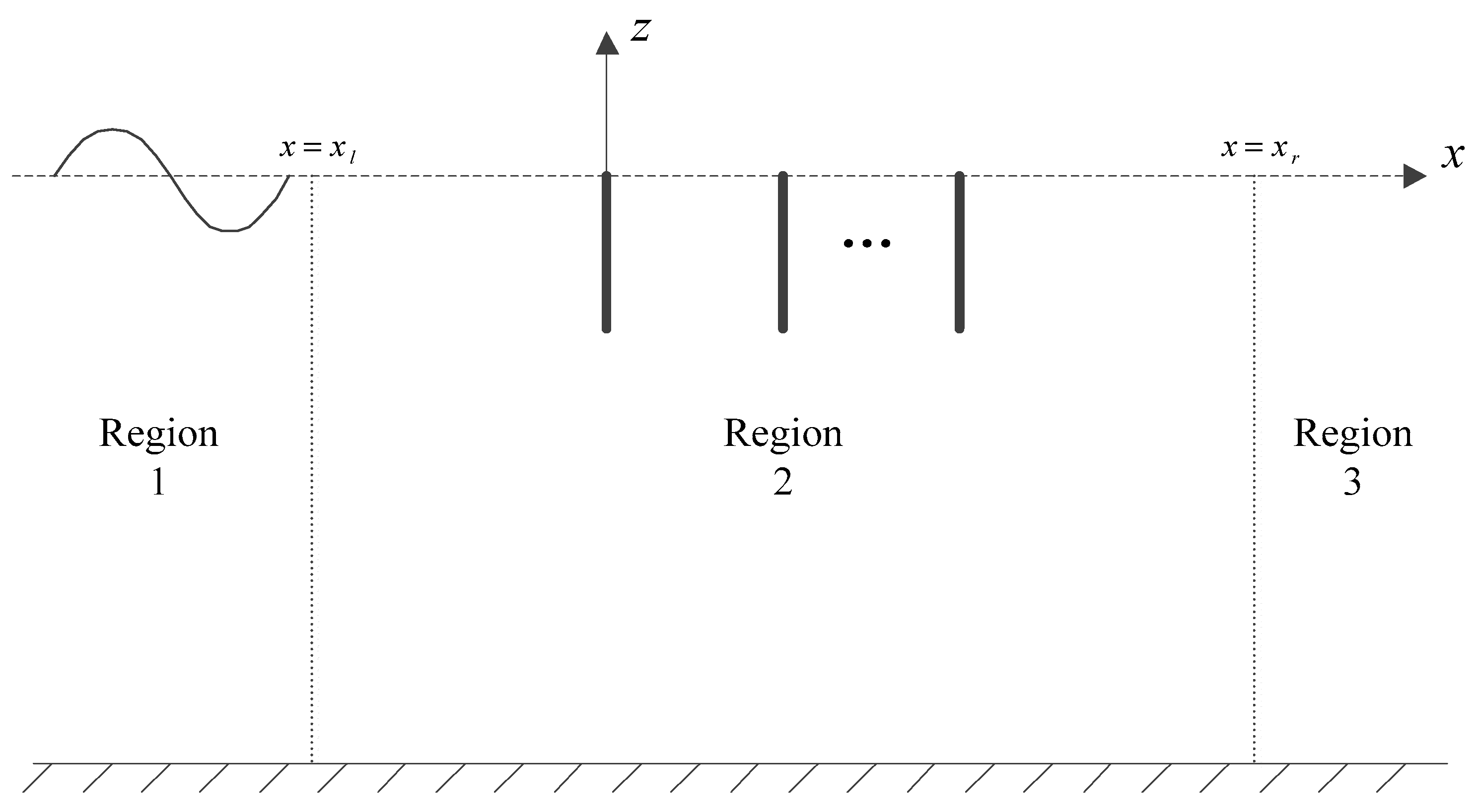
As shown in Figure 1, a two-dimensional Cartesian coordinate system is adopted, with its origin set at the still water surface, the x-axis pointing right horizontally and the z-axis pointing upward vertically. It is assumed that the seabed is rigid and the water depth h is constant. There are N rigid plates with immerged depth d and negligible thicknesses, which are vertically placed downward from the water surface with equal spacing in the horizontal direction. The spacing between two adjacent rigid plates is L, the position of the first rigid plate is at x = 0 , and the position of the j-th rigid plate is at x j = ( j 1 ) L .
The steady monochromatic regime is considered. A monochromatic incident wave with frequency ω and amplitude a m passes through the structure from the far field on the left. Under the assumption of a small amplitude, the wave scattering problem is investigated based on the linear wave theory. It is assumed that the fluid is inviscid and incompressible, and the flow is irrotational and harmonic with respect to time. Thus, the fluid flow can be expressed by the velocity potential Φ ( x , z , t ) in the following form:
Φ ( x , z , t ) = Re { ϕ ( x , z ) e i ω t }
where Re represents the real part, ϕ ( x , z ) is the spatial part of the velocity potential, i = 1 is the imaginary unit, and t denotes time.
The spatial part of the velocity potential of the above-mentioned incident wave can be expressed as
ϕ I = i a m g ω cosh k h e i k x cosh k ( h + z )
where g is the gravitational acceleration, k is the wave number and is the positive real root of the dispersion equation ω 2 = g k tanh k h .
The governing equation of the flow is the two-dimensional Laplace equation:
2 ϕ x 2 + 2 ϕ z 2 = 0
The linearized boundary condition on the free surface is given as
ϕ z ω 2 g ϕ = 0 ,   z = 0
The boundary condition on the surface of the rigid plates is given as
ϕ n = 0
where n represents the unit normal vector.
The impermeable boundary condition on the seabed is
ϕ z = 0 ,   z = h
In order to obtain the unique solution, the velocity potential should satisfy the following far-field radiation condition:
lim x ( x ± i k ) ϕ = 0
So far, a complete boundary value problem for the velocity potential is established.

3. Numerical Solutions

The dual BEM is used to solve the above boundary value problem for the case in which the two ends of each rigid plate are fixed.
As shown in Figure 2, one vertical virtual boundary is set at the position x = x l that is far enough to the left of the first rigid plate; the other vertical virtual boundary is set at the position x = x r that is far enough to the right of the N-th rigid plate. The whole flow field is divided into region 1 ( x x l ), region 2 ( x l < x < x r ), and region 3 ( x x r ).
The velocity potentials in the corresponding regions are denoted by ϕ 1 ( x , z ) , ϕ 2 ( x , z ) , and ϕ 3 ( x , z ) , respectively. The expressions of ϕ 1 ( x , z ) and ϕ 3 ( x , z ) are the same as those in [24]. By utilizing the continuity conditions of velocity potentials ϕ 2 ( x , z ) | x = x l = ϕ 1 ( x , z ) | x = x l and ϕ 2 ( x , z ) | x = x r = ϕ 3 ( x , z ) | x = x r at the two virtual boundaries, it gives:
[ ϕ 2 + 1 i k ϕ 2 x ] x = x l = 2 A I cosh k ( h + z ) cosh k h
[ ϕ 2 1 i k ϕ 2 x ] x = x r = 0
where A I = i a m g ω e i k x l .
The two-dimensional Green function, which is the fundamental solution for Laplace Equation (3), is defined as [39]:
G ( P , Q ) = ln r ( P , Q ) = 1 2 ln [ ( x ξ ) 2 + ( z η ) 2 ]
where P ( x , z ) is the field point at which the boundary conditions are satisfied; Q ( ξ , η ) is the source point where the velocity potential needs to be solved; r = ( x ξ ) 2 + ( z η ) 2 is the distance between the field point and the source point.
When the point P is in region 2, according to the Green’s second theorem, it gives:
2 π ϕ 2 ( P ) = C ( ϕ 2 ( Q ) G ( P , Q ) n G ( P , Q ) ϕ 2 ( Q ) n ) d s
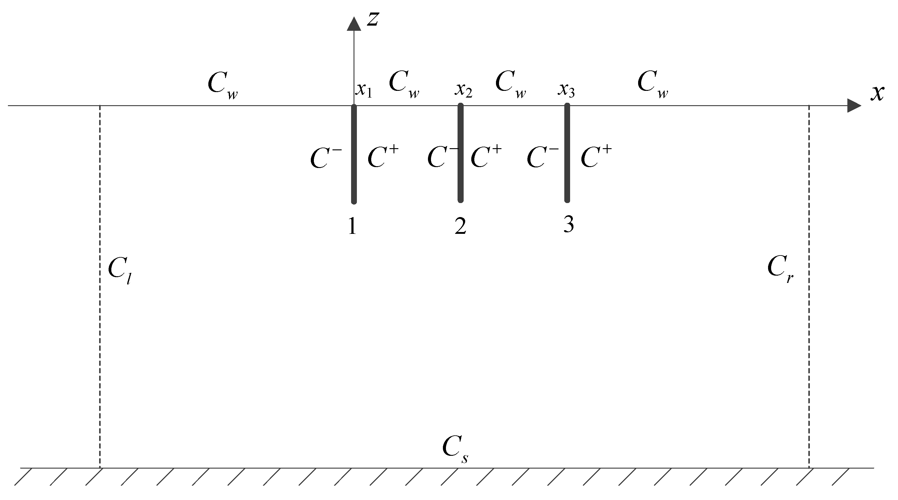
where the direction of the definite integral is anti-clockwise. Boundary C consists of the left virtual boundary C l , the seabed boundary C s , the right virtual boundary C r , several still water surfaces C w , several right boundaries C + of the rigid plates and several left boundaries C of the rigid plates, as shown in Figure 3 (taking three rigid plates as an example).
When the point P is on the boundary of region 2 (excluding the boundary C ), it gives:
π ϕ 2 ( P ) = C ( ϕ 2 ( Q ) G ( P , Q ) n Q G ( P , Q ) ϕ 2 ( Q ) n Q ) d s , P C l , C s , C r , C w , C +
When the point P is on the boundary C of region 2, it gives:
π ϕ 2 ( P ) n P = C ( ϕ 2 ( Q ) 2 G ( P , Q ) n P n Q G ( P , Q ) n P ϕ 2 ( Q ) n Q ) d s , P C
In order to numerically solve the velocity potential on all the boundaries of the whole region 2, all the sub-boundaries are divided into several small elements, and the model of constant source element is adopted, where the velocity potential on each small element keeps constant.
Substituting Equations (4)–(6), (8) and (9) into Equation (12), the following equation is obtained after discretization:
π ϕ 2 e ( P ) + C w ( h P Q ω 2 g g P Q ) ϕ 2 e ( Q ) + C s + C + + C h P Q ϕ 2 e ( Q ) + C l + C r ( h P Q i k g P Q ) ϕ 2 e ( Q ) = C l 2 i k A I cosh k ( h + z ) cosh k h g P Q , P C l , C s , C r , C w , C +
where h P Q = Γ Q G ( P , Q ) n Q d Γ and g P Q = Γ Q G ( P , Q ) d Γ are introduced for the convenience of expression, ϕ 2 e represents the velocity potential on a small element e .
Substituting Equations (4)–(6), (8) and (9) into Equation (13), the following equation is obtained after discretization:
C w ( m P Q ω 2 g l P Q ) ϕ 2 e ( Q ) + C s + C + + C m P Q ϕ 2 e ( Q ) + C l + C r ( m P Q i k l P Q ) ϕ 2 e ( Q ) = C l 2 i k A I cosh k ( h + z ) cosh k h l P Q , P C
where m P Q = Γ Q 2 G ( P , Q ) n P n Q d Γ and l P Q = Γ Q G ( P , Q ) n P d Γ are introduced for the convenience of expression.
h P Q , g P Q , m P Q and l P Q can be calculated by the conventional Gauss quadrature formula. Particularly, when the point Q coincides with the point P, the singularity in the Green function occurs, and h P Q , g P Q , m P Q and l P Q are calculated by the following explicit expressions:
h P Q = 0
g P Q = Δ l 2 π ( 1 + ln 2 Δ l )
m P Q = 2 π Δ l
l P Q = 0
where Δ l is the length of the small element on which the point Q is located.
The total number of small elements is denoted by M. The field point and the source point are set at the midpoint of the corresponding element. The values of ϕ 2 and G are assumed to be constant on each element and equal to the values at the midpoint of the element. M linear algebraic equations analogous to Equations (14) or (15) can be obtained. These linear algebraic equations are further rearranged in matrix form with all the unknowns on the left-hand side and all the knowns on the right-hand side. The numerical program is then developed to obtain the velocity potential on each small element by using Gauss elimination technique.
Same as the derivation in [24], by using the continuity of velocity at the left virtual boundary and multiplying both sides of the resulting equation with cosh k ( h + z ) , it gives:
ϕ 2 ( x l , z ) cosh k ( h + z ) = ( A I + R ) cosh 2 k ( h + z ) cosh k h
Integrating Equation (20) with respect to z from −h to 0, it follows:
R = A I + k n 0 sinh k h h 0 ϕ 2 ( x l , z ) cosh k ( h + z ) d z
where n 0 = 1 2 ( 1 + 2 k h sinh k h ) and R is the complex reflection coefficient.
By using the continuity of velocity at the right virtual boundary and multiplying both sides of the resulting equation with cosh k ( h + z ) , it gives:
ϕ 2 ( x r , z ) cosh k ( h + z ) = T cosh 2 k ( h + z ) cosh k h
Integrating Equation (22) with respect to z from −h to 0, it follows:
T = k n 0 sinh k h h 0 ϕ 2 ( x r , z ) cosh k ( h + z ) d z
where T is the complex transmission coefficient.
Therefore, the reflection coefficient K r and the transmission coefficient K t of the multiple vertical rigid plates are calculated as follows:
K r = | R / A I |
K t = | T / A I |

4. Numerical Results and Discussion

4.1. Validation of the Present Method

This subsection compares the numerical results obtained by the dual BEM with the results in the literature. In the numerical calculation, the density of the fluid, ρ , and the gravitational acceleration, g, are set as ρ = 1025   kg / m 3 and g = 9.81   m / s 2 . The distance of the two virtual surfaces to the nearest plate is set as 4 times the water depth, thus the effects of the wave evanescent terms can be ignored [24]. According to [48], the accuracy requirements can be met by dividing 8 small elements within a wavelength when the constant source is applied. In the present study, denser mesh size is selected. The size of the structure surface mesh is equivalent to that of the free surface mesh. At least 25 small elements are adopted within a wavelength. The number of small elements on each side of the plates is 50. According to numerical experiments, the error of the energy conservation equation K r 2 + K t 2 = 1.0 can be limited within 0.5%.
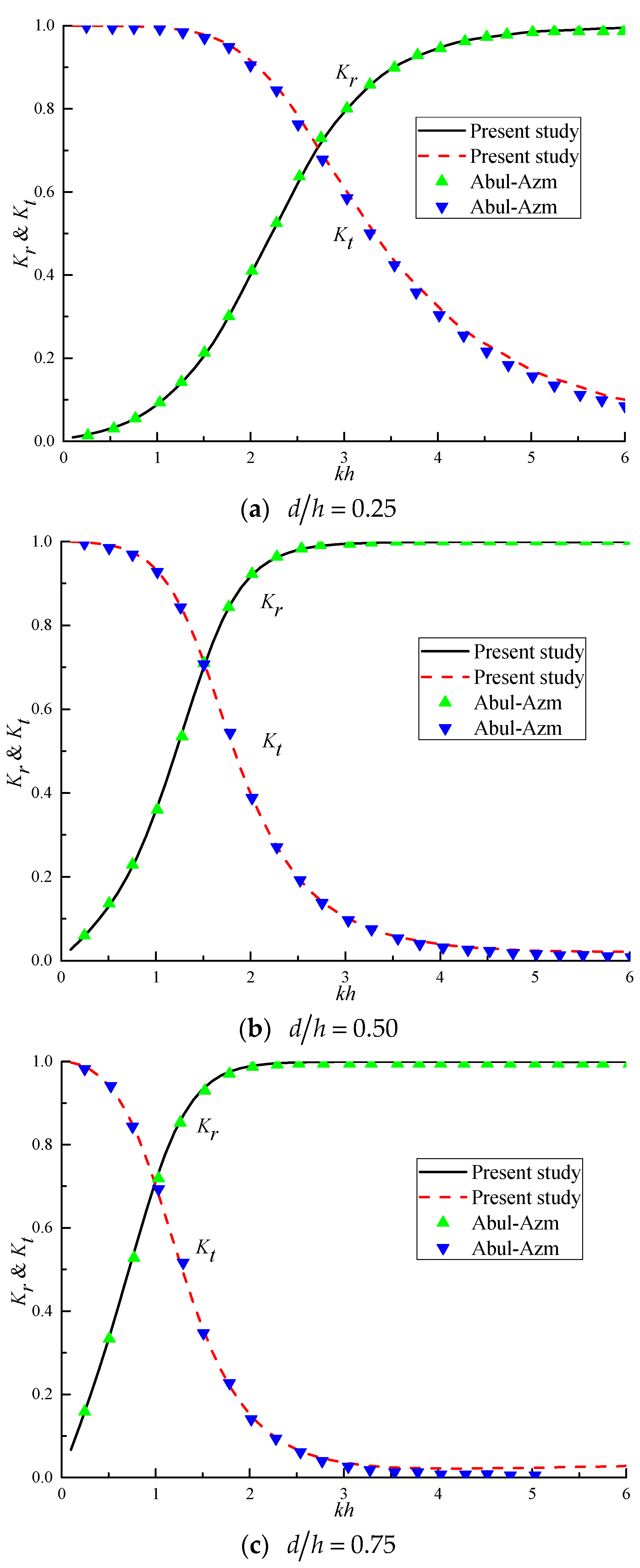
Figure 4 shows the comparison between the results of the reflection coefficient and transmission coefficient of a single vertical rigid plate (N = 1) calculated by the dual BEM and the eigenfunction expansion method in [31] under different ratios of immerged depth to water depth. The eigenfunction expansion method is a traditional analytical method, which has difficulty in handling the complex boundaries. Both methods are based on the linear wave theory and the energy dissipation is negligible. As can be seen from Figure 4, the results obtained by the two methods are in good agreement under three different ratios of immerged depth to water depth. Thus, the results of the reflection and transmission coefficients calculated by the dual BEM can be considered as reliable.

4.2. Definition of the Characteristics of Bragg Reflection

This paper focuses on the characteristics of Bragg reflection when water waves pass through multiple vertical plates. The characteristics of Bragg reflection are represented by three parameters: the occurring condition, the primary reflection coefficient, and the effective bandwidth. As shown in Figure 5, the occurring condition is represented by the corresponding value of 2 L / λ when the Bragg reflection occurs ( λ = 2 π / k ). In practical calculation, the distance between two adjacent plates is always set to several times that of the water depth, thus the value of 2 L / λ can be easily converted and obtained from the corresponding dimensionless wave number kh. The primary reflection coefficient K p is defined as the maximum reflection coefficient corresponding to the occurrence of Bragg reflection. The effective bandwidth E b is defined as the corresponding range of the value of 2 L / λ when the reflection coefficient is not less than half of the primary reflection coefficient in the area where the Bragg reflection occurs [4,24].
In the following subsections, the characteristics of Bragg reflection of water waves by the multiple vertical rigid plates are investigated based on the numerical results of the reflection coefficient calculated by the dual BEM. The effects of the number, the immerged depth and the spacing of the rigid plates on the characteristics of Bragg reflection are analyzed.

4.3. Effects of the Number of Plates

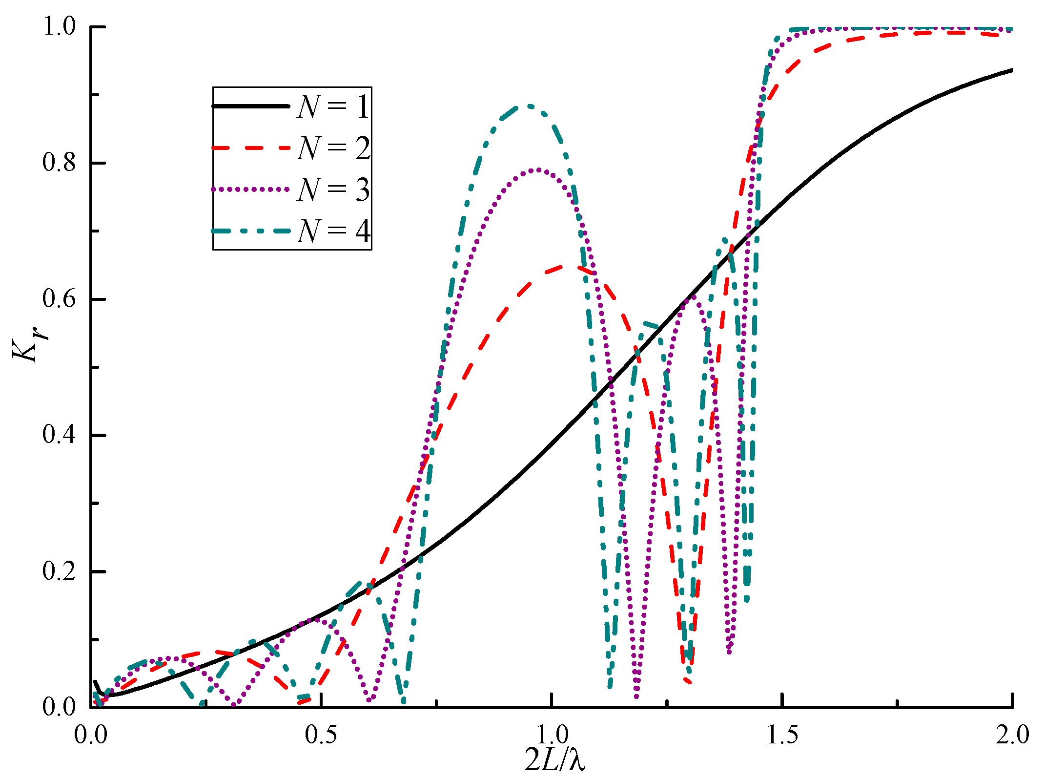
Figure 6 shows the variation of the reflection coefficient K r of the multiple vertical rigid plates versus the dimensionless variable 2 L / λ under different numbers of plates and the calculation conditions d / h = 0.5 and L / h = 3.0 . Table 1 summarizes the corresponding characteristics of Bragg reflection. For a single vertical rigid plate, the value of 2 L / λ is converted from the dimensionless wave number kh and L / h = 3.0 ( 2 L / λ = k h ( L / h ) / π = 3 k h / π ).
In Figure 6, the distance between the plates remains L/h = 3.0 all the time. The variation of wavelength λ leads to the variation of 2 L / λ . The reflection coefficient saturates at 1 for large 2 L / λ due to the small wavelength of the incident wave. It can be seen from Figure 6 that the reflection coefficient of a single vertical rigid plate increases with the increase of the dimensionless wave number. The reflection coefficients of the multiple vertical rigid plates with different numbers of plates vary more complicatedly within the calculation range of 2 L / λ . The larger the number of plates, the larger the corresponding peak and valley values. The occurring conditions of Bragg reflection under different numbers of plates are all in the vicinity of 2 L / λ = 1.0 . It can be observed that the maxima of the reflection coefficients are not exactly at 2 L / λ = 1.0 . This is because the plates are arranged vertically in the water with some distance from the seabed. Similar phenomenon can be found in the previous study on the Bragg reflection of water waves induced by multiple vertical flexible membranes [22,23]. With the increase of the number of plates, the occurring condition of Bragg reflection moves towards the direction of larger wavelength, and the primary reflection coefficient of Bragg reflection increases. When the number of plates is 2, the primary reflection coefficient is K p = 0.65 , and the occurring condition of Bragg reflection is 2 L / λ = 1.04 (the corresponding dimensionless wave number is kh = 1.09). However, the reflection coefficient of a single vertical rigid plate is only K r = 0.42 at kh = 1.09. It indicates that the multiple vertical rigid plates can achieve better wave attenuation than a single vertical rigid plate when applying the principle of Bragg reflection. In addition, the effective bandwidth of Bragg reflection decreases with the increase of the number of plates. It can be deduced that for the case of large N, the Bragg reflection would be strongly enhanced. However, the resonance bandwidth should decrease, which indicates that the range of wavelength suitable for taking advantage of Bragg reflection will be narrow. It is necessary to keep a balance between the primary Bragg reflection and the effective bandwidth. Therefore, the case of large N is not considered in the present study.

4.4. Effects of the Immerged Depth of Plates

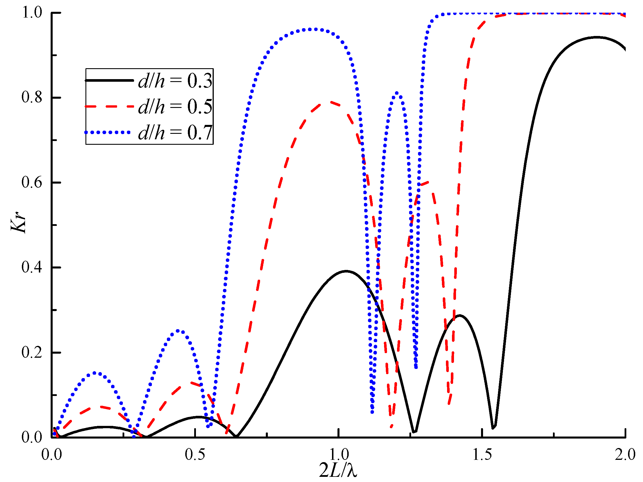
Figure 7 shows the variation of the reflection coefficient K r of the multiple vertical rigid plates versus the dimensionless variable 2 L / λ under different immerged depths of plates and the calculation conditions N = 3 and L / h = 3.0 . Table 2 summarizes the corresponding characteristics of Bragg reflection. The case of d = h is also considered, and the reflection coefficient keeps 1.0, which is apparent and is not presented in the figure and table. It can be seen that under different immerged depths of plates, the number of peaks and troughs of the reflection coefficient curve is the same within the calculation range of 2 L / λ , while the positions of the peaks and troughs are different. The occurring conditions of Bragg reflection under different immerged depths of plates are all in the vicinity of 2 L / λ = 1.0 . With the increase of the immerged depth of plates, the occurring condition of Bragg reflection moves towards the direction of larger wavelength. The primary reflection coefficient of Bragg reflection increases obviously with the increase of the immerged depth of plates. For example, when d/h = 0.7, the primary reflection coefficient is K p = 0.96 , which is close to the total reflection. With the increase of the immerged depth of plates, the effective bandwidth of Bragg reflection increases. The larger the immerged depth of plates, the larger the reflection coefficient within the effective bandwidth; and the effectiveness of wave attenuation becomes better accordingly.

4.5. Effects of the Spacing of Plates

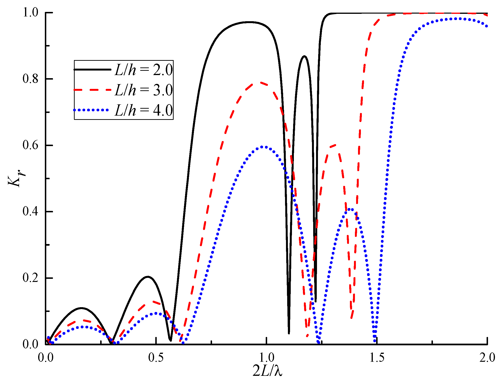
Following the occurring condition of Bragg reflection, theoretically, by choosing a proper spacing, the multiple vertical rigid plates can overcome the deficiency of the single plate in attenuating waves of long wavelength. Figure 8 shows the variation of the reflection coefficient K r of the multiple vertical rigid plates versus the dimensionless variable 2 L / λ under different spacings of plates and the calculation conditions N = 3 and d / h = 0.5 . Table 3 summarizes the corresponding characteristics of Bragg reflection. It can be seen that the number of peaks and troughs of the reflection coefficient curve is the same under different spacings of plates in the calculation range of 2 L / λ . For different spacings of plates, the occurring conditions of Bragg reflection are all in the vicinity of 2 L / λ = 1.0 . However, they are also not exactly at 2 L / λ = 1.0 . Similar phenomenon can be found in [23]. With the increase of the spacing of plates, the occurring condition of Bragg reflection moves towards the direction of smaller wavelength. The primary reflection coefficient of Bragg reflection increases with the decrease of the spacing of plates; however, the wavelength corresponding to the smaller spacing of plates also decreases significantly. For example, when L / h = 2.0 and the Bragg reflection occurs, the wavelength is λ / h = 4.33 , and the primary reflection coefficient is K p = 0.97 ; while when L / h = 4.0 and the Bragg reflection occurs, the wavelength is λ / h = 8.06 , and the primary reflection coefficient is K p = 0.60 . It indicates that although the multiple vertical rigid plates with small spacing of plates can achieve better effectiveness for wave attenuation when applying the principle of Bragg reflection, the wavelength of the attenuated waves is also small. In other words, only enlarging the spacing to attenuate waves of longer wavelengths is not so effective due to the too small amplitude of Bragg reflection. In addition, with the increase of the spacing of plates, the effective bandwidth of Bragg reflection changes very little, while it moves as a whole to the right along the abscissa axis.

5. Model Experiments

5.1. Set-Up and Procedure

A series of model experiments were carried out in a small wave flume with the dimension of 18 m in length, 0.6 m in width and 0.8 m in depth at School of Naval Architecture, Ocean and Energy Power Engineering, Wuhan University of Technology. A piston-type wave maker is installed at one end of the flume to generate linear regular waves. The absorbing section exists at the other end and is totally covered with thick canvas to attenuate the wave reflection from the flume end.
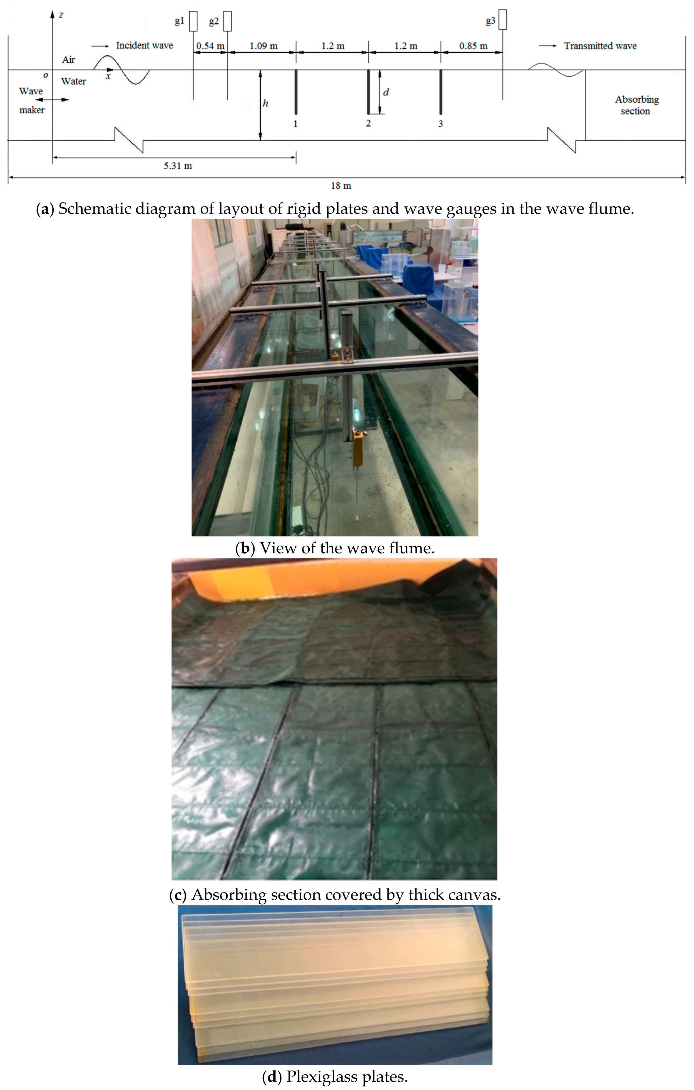
Figure 9 shows the experimental layout of multiple vertical rigid plates, where Figure 9a depicts a schematic diagram of the layout of the three-plate experimental model and wave gauges in the wave flume; Figure 9b depicts a view of the wave flume with installed experimental model; Figure 9c is a photo of the absorbing section covered by thick canvas; and Figure 9d is a photo of plexiglass plates used in the experiments.
The model of multiple rigid plates was composed of several identical plexiglass plates. During the experiments, the position of the first rigid plate facing the incident waves remained stationary, and the position of the wave gauges g1 and g2 between the first rigid plate and the wave maker also remained stationary. When increasing the number of the plates, the rigid plates were set one by one at the same distance behind the first rigid plate, and the position of the wave gauge g3 behind the plate was adjusted accordingly. The distance between two adjacent plates was fixed at 1.2 m. Each plate had a thickness of 5 mm and a width of 0.595 m in the width direction of the wave flume. Each plate was vertically fixed and immerged from the still water surface downward into the water. The immerged depth of the plate was 0.12 m, 0.15 m and 0.18 m, respectively; the number of plates was 1, 2 and 3, respectively.
Throughout the experiments, the water depth h was 0.3 m. In order to meet the requirements of linear regular waves and make the wave height as large as possible, the wave steepness was set to be ε = 0.003 (ε is equal to the ratio of wave height H to wave length λ). Considering the limitations of the length of the experimental section of the wave flume and the positions of wave gauges used in the wave flume, the wave period was set to vary from 1.2 s to 1.9 s with an interval of 0.1 s, 8 groups in total. Once the wave period was determined, the wavelength could be obtained based on the water wave dispersion relation, and the wave height was determined accordingly. The corresponding wavelength range was 1.769~3.075 m, and the corresponding wave height varied from 5 mm to 9 mm.
The experimental parameters are summarized in Table 4. Each experiment was repeated three times to reduce accidental errors.
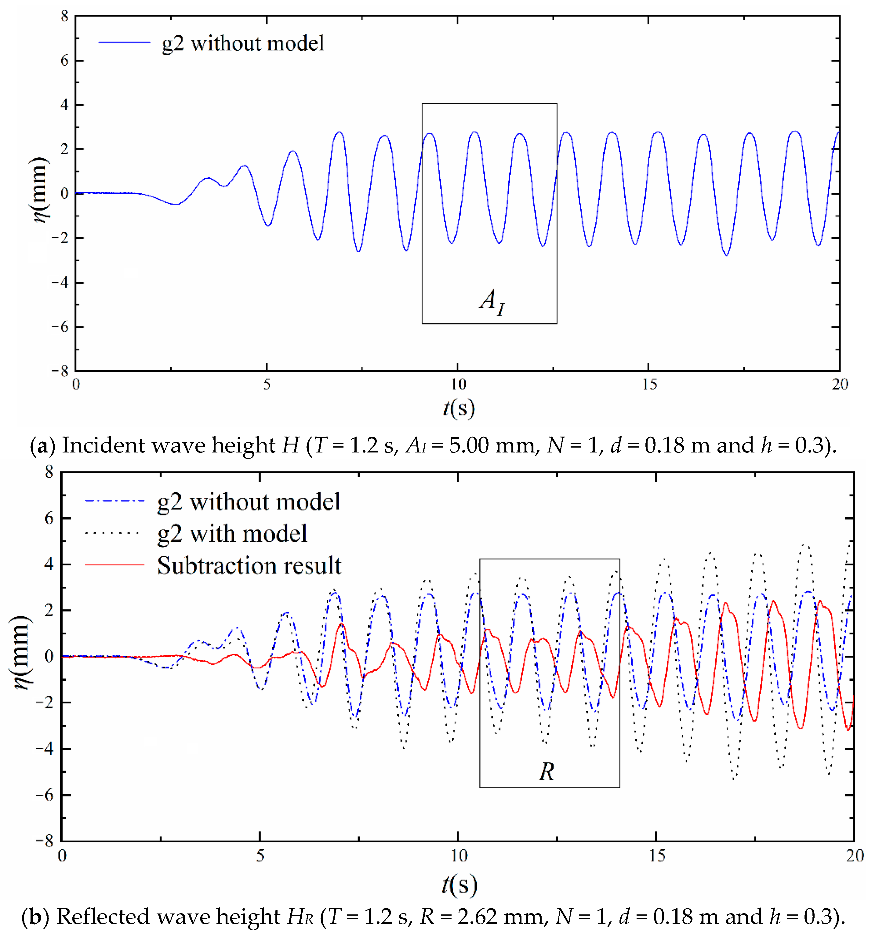
The capacitance-type digital wave gauges were used to measure the wave surface elevation, which had a measurement range of 0~30 cm, an absolute error of less than ±1 mm and a frequency resolution of 100 Hz. The wave gauge g3 was used to directly compute the transmitted wave height [37]. The wave gauge g2 installed at 1.09 m in front of the first rigid plate was used to analyze the incident wave height and reflected wave height. Figure 10 shows the illustration of the incident wave height and reflected wave height, where a kind of fixed single-point method of reflection wave decomposition was used to gain the reflected wave height [49]. Specifically, the incident wave height was computed from the wave elevation recording of wave gauge g2 without the plate model, which was the averaged wave height in the block diagram of Figure 10a. The subtraction result representing the reflected wave sequence was computed by subtracting the wave elevation recording of wave gauge g2 without plate model from the wave elevation recording of wave gauge g2 with plate model. The reflected wave height is represented by the averaged wave height of the subtraction result in the block diagram of Figure 10b. The number of waves used to calculate the averaged wave height was selected as 3 due to the constraints of the length of wave flume and the range of wavelengths in the present study.

5.2. Comparison of Results

This subsection compares the experimental results with the numerical results obtained by the dual BEM.
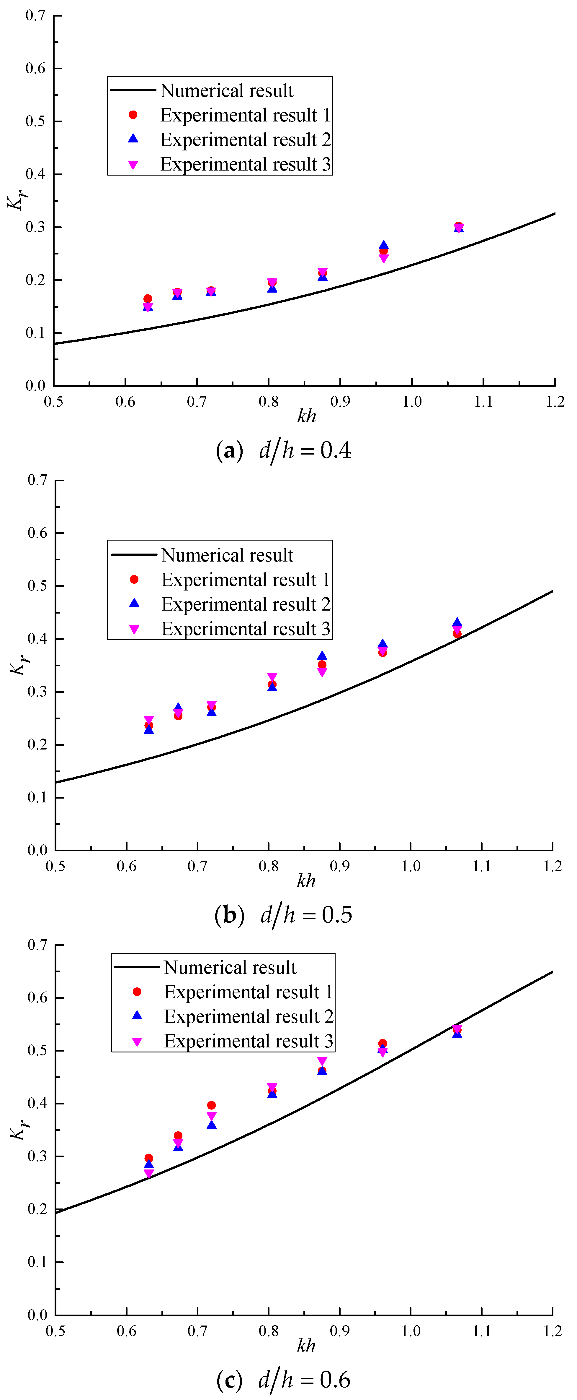
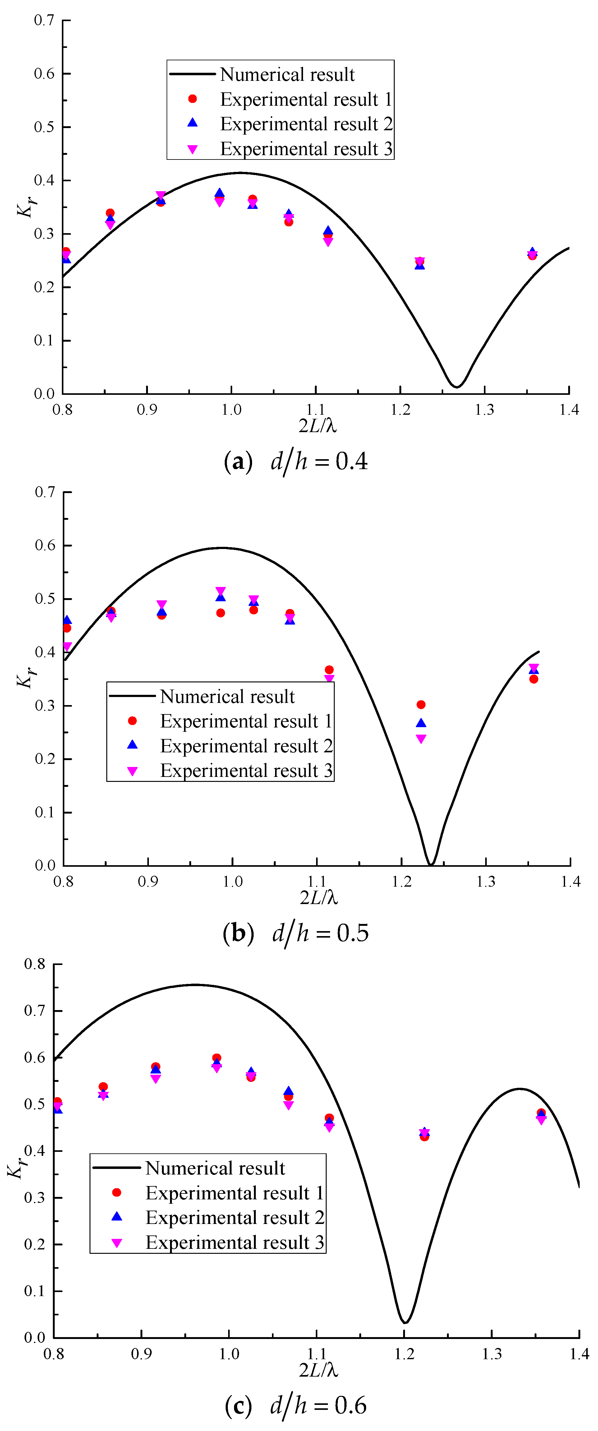
For a single vertical rigid plate (N = 1), Figure 11 shows the comparison between the numerical results of the reflection coefficient calculated by the dual BEM and the model experimental results under different ratios of immerged depth to water depth. For the multiple vertical rigid plates (N = 2, 3 and L / h = 4.0 ), Figure 12 and Figure 13 show, respectively, the comparison between the numerical results of the reflection coefficient calculated by the dual BEM and the model experimental results under different ratios of immerged depth to water depth.
It can be observed from Figure 11, Figure 12 and Figure 13 that the numerical results and the experimental results have similar variation trends, although there are some differences between them. Overall, the agreement between the experimental results and the numerical results is average, especially when there are two or three plates. The points of full transmission are not retrieved in the experiment, which is a major difference. For multiple plates, the reflection coefficient obtained from the numerical model can reach nearly zero. This is because the incident wave is reflected several times by these plates. When the superposition of the reflected waves is destructive, the reflection coefficient will be small and even nearly zero. For a single vertical rigid plate, the variation trend of the numerical results is particularly consistent with the experimental results, and the numerical results are only slightly smaller than the experimental results. For the multiple vertical rigid plates (N = 2 and N = 3), both numerical and experimental results show that peak values appear in the region where Bragg reflection occurs. For N = 2 and L / h = 4.0 , in the region where Bragg reflection occurs, the numerical results at the large wavelength are slightly smaller than the experimental results, and the numerical results at the small wavelength are slightly larger than the experimental results. However, for N = 3 and L / h = 4.0 , in the region where Bragg reflection occurs, the numerical results are larger than the experimental results, and the difference increases with the increase of the immerged depth of the plates.
The differences between the numerical results and the experimental results are mainly due to the following reasons: The fluid viscosity is neglected in the numerical calculation, while the experiments were carried out in the real viscous fluid; the effect of the plate thickness is neglected in the numerical calculation, while the plates in the experiments had a certain thickness, although it was very thin; the plates are assumed to be fixed in the numerical calculation, while in the experiments they vibrated and deformed slightly under the action of wave force; and no overtopping is considered in the numerical calculation, while the water could pass over the plates in the experiments. In addition, the limitations of the experimental equipment, the errors generated by the measuring instruments, and the existence of small gaps between the plates and the flume wall may also be the reasons for the differences between the numerical results and the experimental results.

6. Conclusions

In this study, the Bragg reflection of water waves by multiple vertical rigid plates with equal spacing fixed in the water is studied. Based on the linear water wave theory, the wave scattering problem of the structure is established, and the reflection and transmission coefficients of the wave passing through the structure are obtained using the dual BEM. By comparing them with the theoretical results in the literature, the accuracy of the numerical results of the reflection coefficient and transmission coefficient is verified. For multiple vertical rigid plates with different numbers, immerged depths and spacings, the reflection coefficient is calculated by the dual BEM. On this basis, the effects of the number, immerged depth and spacing of the multiple vertical rigid plates on the characteristics of Bragg reflection of waves are systematically analyzed. Additionally, model experiments were carried out and the experimental results were used to compare with the numerical results of the reflection coefficient.
It is found that the occurring condition of Bragg reflection moves to the left along the abscissa axis with the increase of the number of plates, the increase of the immerged depth of the plates and the decrease of the spacing of the plates. The primary reflection coefficient of Bragg reflection increases with the increase of the number of the plates, the increase of the immerged depth of the plates and the decrease of the spacing of the plates. The effective bandwidth of Bragg reflection increases with the decrease of the number of the plates and the increase of the immerged depth of the plates. With the increase of the spacing of the plates, the effective bandwidth of Bragg reflection changes little, but moves to the right as a whole. The variation trends of the numerical and experimental results are similar, and the agreements in the area where Bragg reflection occurs are acceptable. This study can provide guidance on the design of multiple vertical thin plates as effective breakwaters by taking advantage of Bragg reflection. For practical engineering, such vertical thin plates not fixed on the bed cannot easily resist against the wave forces. The proposed vertical plates need to be attached to the piles in the water to remain fixed.
In the future study, some meaningful research topics on the characteristics of Bragg reflection include the permeability of vertical plates, nonlinear effects of waves and irregular waves incident from different directions in real sea states.

Author Contributions

Conceptualization, W.-W.D., J.-P.W. and Z.-J.Z.; methodology, W.-W.D. and J.-P.W.; software, W.-W.D.; validation, W.-W.D. and J.-P.W.; formal analysis, W.-W.D.; investigation, W.-W.D. and J.-P.W.; resources, W.-W.D.; data curation, W.-W.D. and J.-P.W.; writing—original draft preparation, W.-W.D., W.-Z.Y. and J.-P.W.; writing—review and editing, W.-W.D., W.-Z.Y., S.-W.S., J.-P.W. and Z.-J.Z.; visualization, W.-W.D.; supervision, S.-W.S. and Z.-J.Z.; project administration, S.-W.S. and Z.-J.Z.; funding acquisition, S.-W.S. and Z.-J.Z. All authors have read and agreed to the published version of the manuscript.

Funding

This research was funded by the National Key R&D Program of China, grant number 2019YFB1504401; the Key Special Project for Introduced Talents Team of Southern Marine Science and Engineering Guangdong Laboratory (Guangzhou), grant number GML2019ZD0107 and the Key Laboratory of Renewable Energy, Chinese Academy of Sciences, grant number E129060101.

Institutional Review Board Statement

Not applicable.

Informed Consent Statement

Not applicable.

Data Availability Statement

The data used to support the findings of this study are available from the corresponding author upon request.

Conflicts of Interest

The authors declare no conflict of interest.

References

  1. Bragg, W.H.; Bragg, W.L. The reflection of X-rays by crystals. Proc. R. Soc. Lond. Ser. A-Math. Phys. Character 1913, 88, 428–438. [Google Scholar] [CrossRef]
  2. Heathershaw, A.D. Seabed-wave resonance and sand bar growth. Nature 1982, 296, 343–345. [Google Scholar] [CrossRef]
  3. Mei, C.C.; Hara, T.; Naciri, M. Note on Bragg scattering of water waves by parallel bars on the seabed. J. Fluid Mech. 1988, 186, 147–162. [Google Scholar] [CrossRef]
  4. Bailard, J.A.; DeVries, J.W.; Kirby, J.T. Considerations in using Bragg reflection for storm erosion protection. J. Waterw. Port Coast. Ocean Eng. 1992, 118, 62–74. [Google Scholar] [CrossRef] [Green Version]
  5. Tao, A.F.; Yan, J.; Wang, Y.; Zheng, J.H.; Fan, J.; Qin, C. Wave power focusing due to the Bragg resonance. China Ocean Eng. 2017, 31, 458–465. [Google Scholar] [CrossRef]
  6. Gao, J.; Ma, X.; Dong, G.; Chen, H.; Liu, Q.; Zhang, J. Investigation on the effects of Bragg reflection on harbor oscillations. Coast. Eng. 2021, 170, 103977. [Google Scholar] [CrossRef]
  7. Chang, J.Y.; Tsai, C.C. Wave forces on a partially reflecting wall by oblique Bragg scattering with porous breakwaters over uneven bottoms. J. Mar. Sci. Eng. 2022, 10, 409. [Google Scholar] [CrossRef]
  8. Zeng, H.; Qin, B.; Zhang, J. Optimal collocation of Bragg breakwaters with rectangular bars on sloping seabed for Bragg resonant reflection by long waves. Ocean Eng. 2017, 130, 156–165. [Google Scholar] [CrossRef]
  9. Ni, Y.L.; Teng, B. Bragg resonant reflection of water waves by a Bragg breakwater with porous rectangular bars on a sloping permeable seabed. Ocean Eng. 2021, 235, 109333. [Google Scholar] [CrossRef]
  10. Chang, H.K.; Liou, J.C. Long wave reflection from submerged trapezoidal breakwaters. Ocean Eng. 2007, 34, 185–191. [Google Scholar] [CrossRef]
  11. Liu, H.W.; Zeng, H.D.; Huang, H.D. Bragg resonant reflection of surface waves from deep water to shallow water by a finite array of trapezoidal bars. Appl. Ocean Res. 2020, 94, 101976. [Google Scholar] [CrossRef]
  12. Kar, P.; Koley, S.; Sahoo, T. Bragg scattering of long waves by an array of trenches. Ocean Eng. 2020, 198, 107004. [Google Scholar] [CrossRef]
  13. Guo, F.C.; Liu, H.W.; Pan, J.J. Phase downshift or upshift of Bragg resonance for water wave reflection by an array of cycloidal bars or trenches. Wave Motion 2021, 106, 102794. [Google Scholar] [CrossRef]
  14. Liu, Y.; Li, H.; Zhu, L. Bragg reflection of water waves by multiple submerged semi-circular breakwaters. Appl. Ocean Res. 2016, 56, 67–78. [Google Scholar] [CrossRef]
  15. Li, A.; Liu, Y.; Liu, X.; Zhao, Y. Analytical and experimental studies on Bragg scattering of water waves by multiple submerged perforated semi-circular breakwaters. Ocean Eng. 2020, 209, 107419. [Google Scholar] [CrossRef]
  16. Liu, H.W.; Shi, Y.P.; Cao, D.Q. Optimization of parabolic bars for maximum Bragg resonant reflection of long waves. J. Hydrodyn. 2015, 27, 373–382. [Google Scholar] [CrossRef]
  17. Hao, J.; Li, J.; Liu, S.; Wang, L. Wave amplification caused by Bragg resonance on parabolic-type topography. Ocean Eng. 2022, 244, 110442. [Google Scholar] [CrossRef]
  18. Liu, H.W. Band gaps for Bloch waves over an infinite array of trapezoidal bars and triangular bars in shallow water. Ocean Eng. 2017, 130, 72–82. [Google Scholar] [CrossRef]
  19. Zhang, H.; Tao, A.; Tu, J.; Sun, J.W.; Xie, S.Y. The focusing waves induced by Bragg resonance with V-shaped undulating bottom. J. Mar. Sci. Eng. 2021, 9, 708. [Google Scholar] [CrossRef]
  20. Karmakar, D.; Bhattacharjee, J.; Guedes Soares, C. Scattering of gravity waves by multiple surface-piercing floating membrane. Appl. Ocean Res. 2013, 39, 40–52. [Google Scholar] [CrossRef]
  21. Ouyang, H.T.; Chen, K.H.; Tsai, C.M. Investigation on Bragg reflection of surface water waves induced by a train of fixed floating pontoon breakwaters. Int. J. Nav. Archit. Ocean Eng. 2015, 7, 951–963. [Google Scholar] [CrossRef] [Green Version]
  22. Ding, W.W.; Zou, Z.J.; Wu, J.P. Bragg reflection of water waves by multiple composite flexible membranes. Int. J. Offshore Polar Eng. 2018, 28, 135–142. [Google Scholar] [CrossRef]
  23. Ding, W.W.; Zou, Z.J.; Wu, J.P. Characteristics of Bragg reflection of water waves by multiple vertical flexible membranes. In Proceedings of the 37th International Conference on Ocean, Offshore and Arctic Engineering, Madrid, Spain, 17–22 June 2018. [Google Scholar]
  24. Ding, W.W.; Zou, Z.J.; Wu, J.P.; Huang, B.G. Investigation of surface-piercing fixed structures with different shapes for Bragg reflection of water waves. Int. J. Nav. Archit. Ocean Eng. 2019, 11, 819–827. [Google Scholar] [CrossRef]
  25. Ding, W.W.; Zou, Z.J.; Wu, J.P. Bragg reflection of water waves by multiple floating horizontal flexible membranes with submerged rectangular bars on the seabed. Appl. Ocean Res. 2019, 83, 103–111. [Google Scholar] [CrossRef]
  26. Tseng, I.F.; You, C.S.; Tsai, C.C. Bragg reflections of oblique water waves by periodic surface-piercing and submerged breakwaters. J. Mar. Sci. Eng. 2020, 8, 522. [Google Scholar] [CrossRef]
  27. Kar, P.; Sahoo, T.; Meylan, M.H. Bragg scattering of long waves by an array of floating flexible plates in the presence of multiple submerged trenches. Phys. Fluids 2020, 32, 096603. [Google Scholar] [CrossRef]
  28. Mohapatra, A.K.; Vijay, K.G.; Sahoo, T. Bragg scattering of surface gravity waves by a submerged wavy porous plate. Ocean Eng. 2021, 219, 108273. [Google Scholar] [CrossRef]
  29. Verduzco-Zapata, M.G.; García-Nava, H.; Ocampo-Torres, F.J.; Mendoza, E.; Ramírez-Serrano, E.I.; Torres-Orozco, E. Ocean surface waves propagating over a spatial arrangement of subsurface fixed horizontal plate breakwaters crowned with flexible medium. J. Fluids Struct. 2021, 100, 103188. [Google Scholar] [CrossRef]
  30. Zhao, X.; Xue, R.; Geng, J.; Göteman, M. Analytical investigation on the hydrodynamic performance of a multi-pontoon breakwater-WEC system. Ocean Eng. 2021, 220, 108394. [Google Scholar] [CrossRef]
  31. Abul-Azm, A.G. Wave diffraction through submerged breakwaters. J. Waterw. Port Coast. Ocean Eng. 1993, 119, 587–605. [Google Scholar] [CrossRef]
  32. Losada, I.J.; Losada, M.A.; Roldán, A.J. Propagation of oblique incident waves past rigid vertical thin barriers. Appl. Ocean Res. 1992, 14, 191–199. [Google Scholar] [CrossRef]
  33. Cao, F.S.; Teng, B. Scaled boundary finite element analysis of wave passing a submerged breakwater. China Ocean Eng. 2008, 22, 241–251. [Google Scholar]
  34. Liu, Y.; Xie, L.; Zhang, Z. The wave motion over a submerged Jarlan-type perforated breakwater. Acta Oceanol. Sin. 2014, 33, 96–102. [Google Scholar] [CrossRef]
  35. Mandal, S.; Behera, H.; Sahoo, T. Oblique wave interaction with porous, flexible barriers in a two-layer fluid. J. Eng. Math. 2015, 100, 1–31. [Google Scholar] [CrossRef]
  36. Jaf, J.M.; Wang, K.H. Interaction of solitary waves with a submerged impermeable breakwater. J. Eng. Mech. 2015, 141, 04015030. [Google Scholar] [CrossRef]
  37. Wu, J.P.; Pan, J.; Ding, W.W.; Zou, Z.J.; Li, T.Q. Experimental studies on the transmission coefficients of multiple plates. In Proceedings of the 26th International Ocean and Polar Engineering Conference, Rhodes, Greece, 26 June–1 July 2016. [Google Scholar]
  38. Miao, Y.; Wang, K.H. Approximate analytical solutions for a solitary wave interacting with a partially submerged porous wall. Ocean Eng. 2019, 181, 227–239. [Google Scholar] [CrossRef]
  39. Yueh, C.Y.; Tsaur, D.H. Wave scattering by submerged vertical plate-type breakwater using composite BEM. Coast Eng. J. 1999, 41, 65–83. [Google Scholar] [CrossRef]
  40. Chen, K.H.; Chen, J.T.; Chou, C.R.; Yueh, C.Y. Dual boundary element analysis of oblique incident wave passing a thin submerged breakwater. Eng. Anal. Bound. Elem. 2002, 26, 917–928. [Google Scholar] [CrossRef]
  41. Yueh, C.Y.; Chuang, S.H.; Wen, C.C. Wave scattering by submerged composite wavy plate breakwaters using a dual BEM. Ocean Eng. 2016, 124, 192–203. [Google Scholar] [CrossRef]
  42. Chen, J.T.; Yueh, C.Y.; Chang, Y.L.; Wen, C.C. Why dual boundary element method is necessary? Eng. Anal. Bound. Elem. 2017, 76, 59–68. [Google Scholar] [CrossRef]
  43. Yueh, C.Y.; Chuang, S.H.; Wen, C.C. Scattering of water waves by surface-piercing barriers using dual BEM. J. Hydro-Environ. Res. 2018, 21, 21–28. [Google Scholar] [CrossRef]
  44. Vijay, K.G.; Venkateswarlu, V.; Nishad, C.S. Wave scattering by inverted trapezoidal porous boxes using dual boundary element method. Ocean Eng. 2021, 219, 108149. [Google Scholar] [CrossRef]
  45. Nishad, C.S.; Vijay, K.G.; Neelamani, S.; Chen, J.T. Dual BEM for wave scattering by an H-type porous barrier with nonlinear pressure drop. Eng. Anal. Bound. Elem. 2021, 131, 280–294. [Google Scholar] [CrossRef]
  46. Vijay, K.G.; Nishad, C.S.; Neelamani, S.; Sahoo, T. Wave interaction with multiple wavy porous barriers using dual boundary element method. Eng. Anal. Bound. Elem. 2021, 122, 176–189. [Google Scholar] [CrossRef]
  47. Koley, S.; Vijay, K.G.; Nishad, C.S.; Sundaravadivelu, R. Performance of a submerged flexible membrane and a breakwater in the presence of a seawall. Appl. Ocean Res. 2022, 124, 103203. [Google Scholar] [CrossRef]
  48. Liu, P.L.F.; Abbaspour, M. An integral equation method for the diffraction of oblique waves by an infinite cylinder. Int. J. Numer. Methods Eng. 1982, 18, 1497–1504. [Google Scholar] [CrossRef]
  49. Wu, J.P.; Bo, H.; Zhang, M.; Pan, J. A Reflection Wave Decomposition Method Based on the Linear Superposition Principle of Water Waves. CN201710605897.4, 24 July 2017. [Google Scholar]
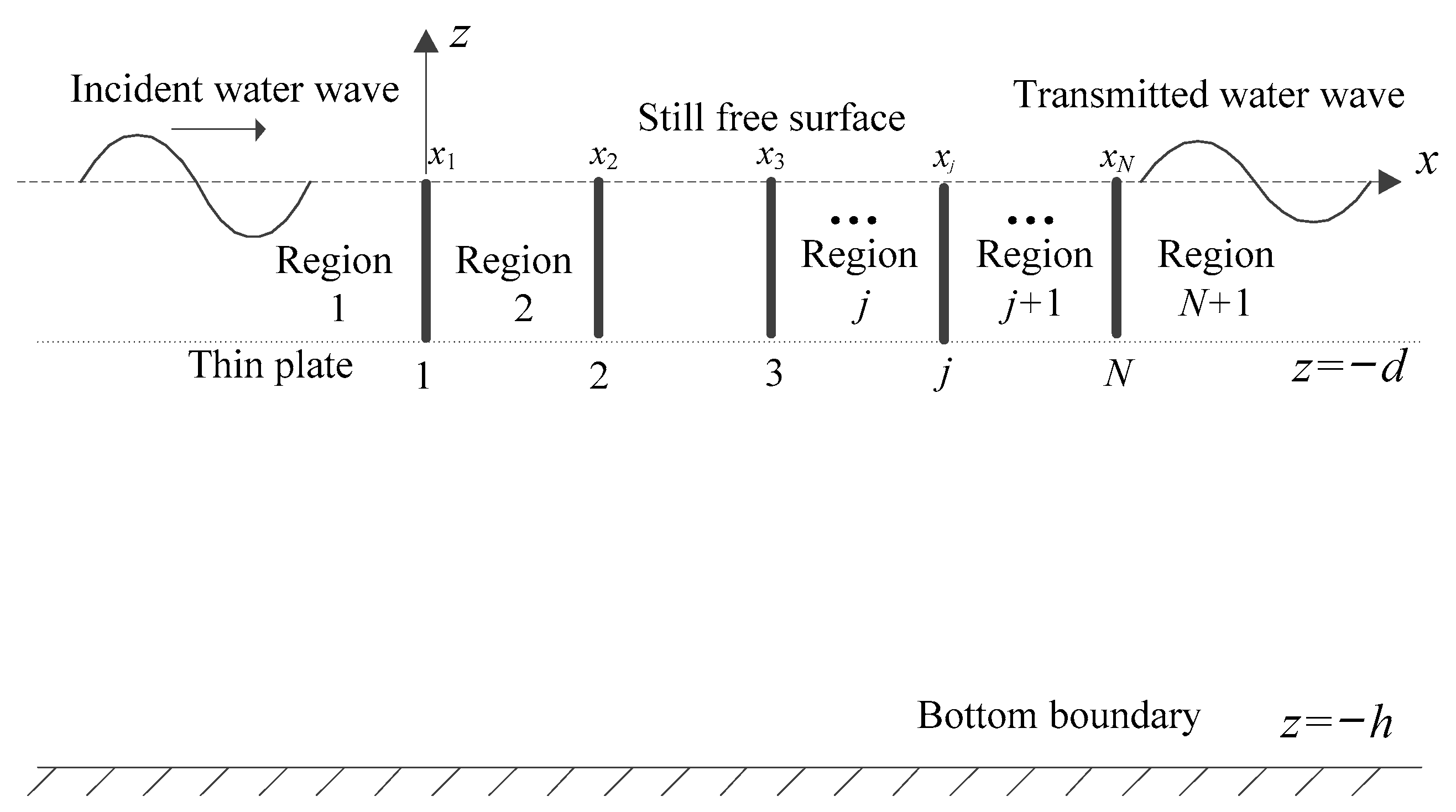
Figure 1. Schematic diagram of multiple vertical rigid plates.
Jmse 10 01464 g001
Figure 2. Division of flow field region.
Jmse 10 01464 g002
Figure 3. Diagram of boundary division.
Jmse 10 01464 g003
Figure 4. Comparisons of the numerical and analytical results of reflection and transmission coefficients.
Jmse 10 01464 g004
Figure 5. Definition of the characteristics of Bragg reflection.
Jmse 10 01464 g005
Figure 6. Reflection coefficient versus 2 L / λ under different numbers of plates ( d / h = 0.5 and L / h = 3.0 ).
Jmse 10 01464 g006
Figure 7. Reflection coefficient versus 2 L / λ under different immerged depths of plates ( N = 3 and L / h = 3.0 ).
Jmse 10 01464 g007
Figure 8. Reflection coefficient versus 2 L / λ under different spacings of plates ( N = 3 and d / h = 0.5 ).
Jmse 10 01464 g008
Figure 9. Experimental set-up of multiple vertical rigid plates.
Jmse 10 01464 g009
Figure 10. Illustration of the incident wave height H and reflected wave height HR.
Jmse 10 01464 g010
Figure 11. Comparisons of the numerical and experimental reflection coefficients (N = 1).
Jmse 10 01464 g011
Figure 12. Comparisons of the numerical and experimental reflection coefficients ( N = 2 and L / h = 4.0 ).
Jmse 10 01464 g012
Figure 13. Comparisons of the numerical and experimental reflection coefficients ( N = 3 and L / h = 4.0 ).
Jmse 10 01464 g013
Table 1. Characteristics of Bragg reflection under different numbers of plates ( d / h = 0.5 and L / h = 3.0 ).
N2L/λ 1 K p E b
1--0.42--
21.040.650.71~1.24
30.960.790.74~1.14
40.950.880.75~1.09
1 2L/λ value represents that the Bragg reflection occurs.
Table 2. Characteristics of Bragg reflection under different immerged depths of plates ( N = 3 and L / h = 3.0 ).
d/h2L/λ K p E b
0.31.030.390.81~1.19
0.50.960.790.74~1.14
0.70.910.960.63~1.10
Table 3. Characteristics of Bragg reflection under different spacings of plates ( N = 3 and d / h = 0.5 ).
L/h2L/λ K p E b
2.00.920.970.64~1.08
3.00.960.790.74~1.14
4.00.990.600.76~1.16
Table 4. Experimental parameters of multiple vertical rigid plates.
ParameterUnitValue
Water depth hm0.3
Wavelength λm1.769~3.075
Wave steepness ε--0.003
Wave period Ts1.2~1.9
Wave height Hmm5~9
Number of plates N--1, 2, 3
Immerged depth dm0.12, 0.15, 0.18
Spacing of plates Lm1.2
Publisher’s Note: MDPI stays neutral with regard to jurisdictional claims in published maps and institutional affiliations.