
A Review on Hydrodynamic Performance and Design of Pump-Jet: Advances, Challenges and Prospects


Abstract
:1. Introduction
2. Performance Evaluation
2.1. Hydrodynamic Performance
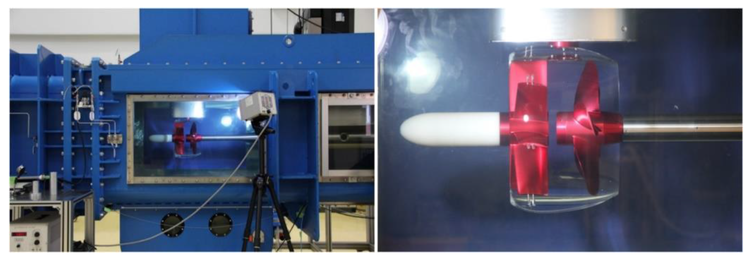
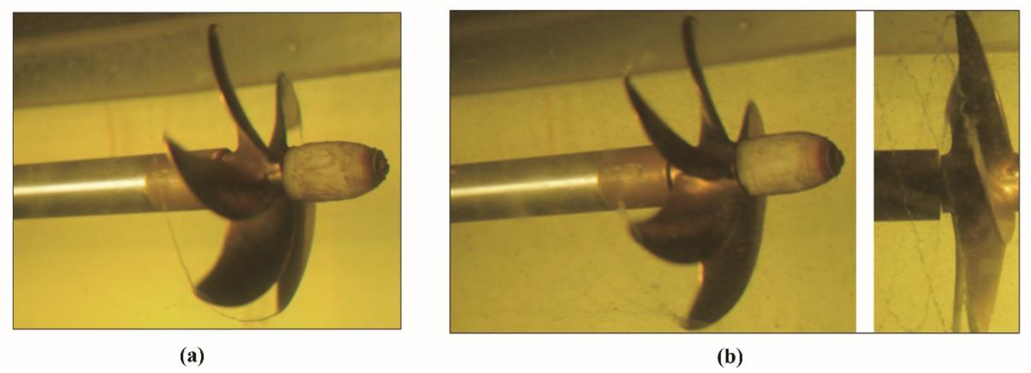
2.1.1. Investigation Techniques
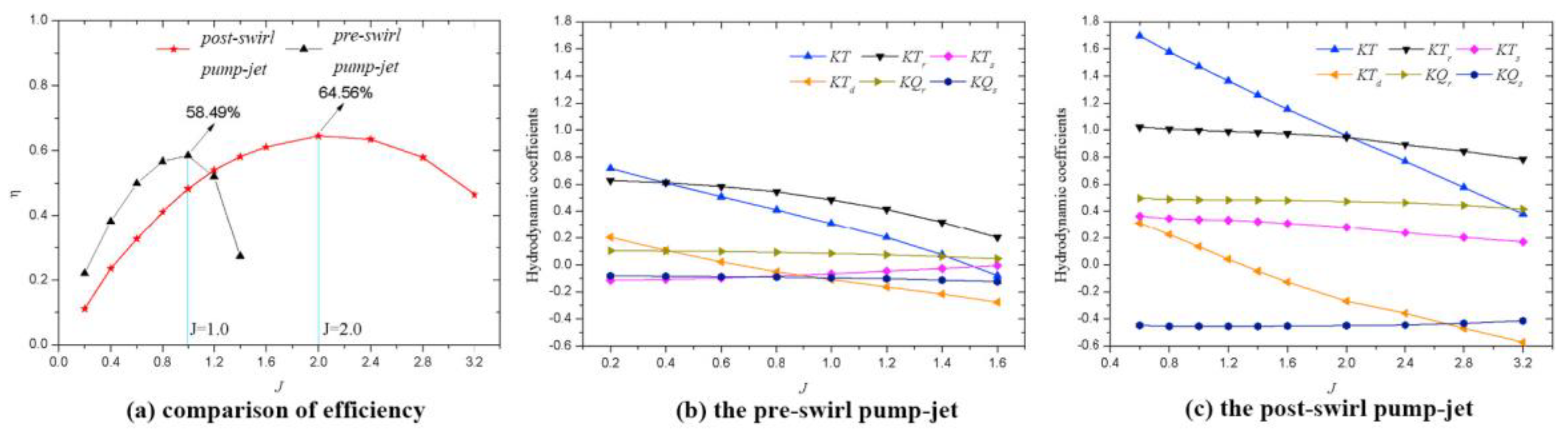
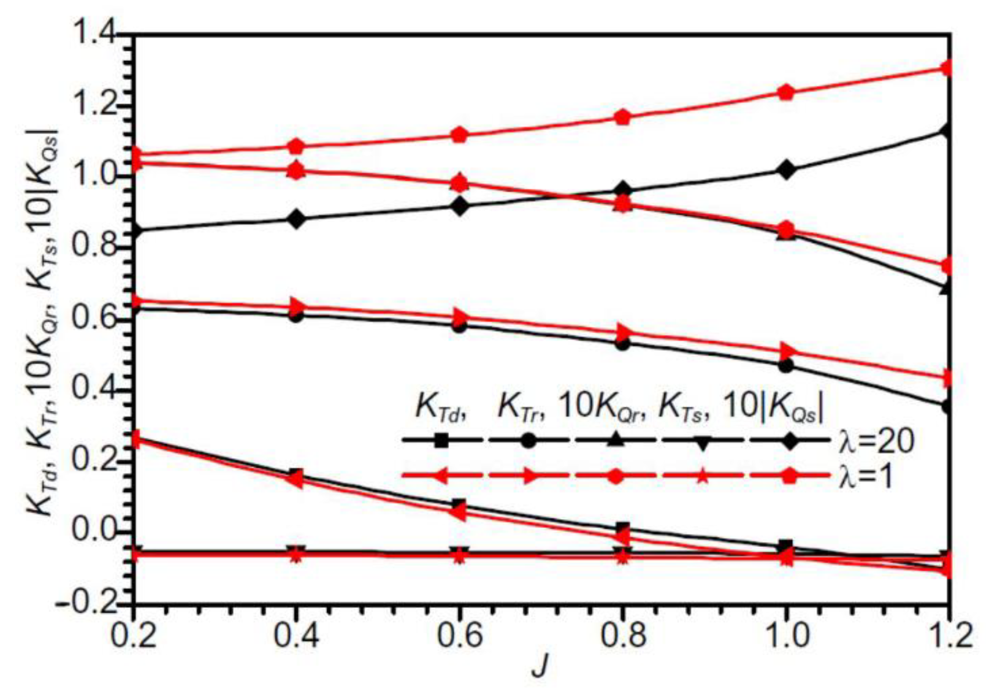
2.1.2. Propulsion Performance


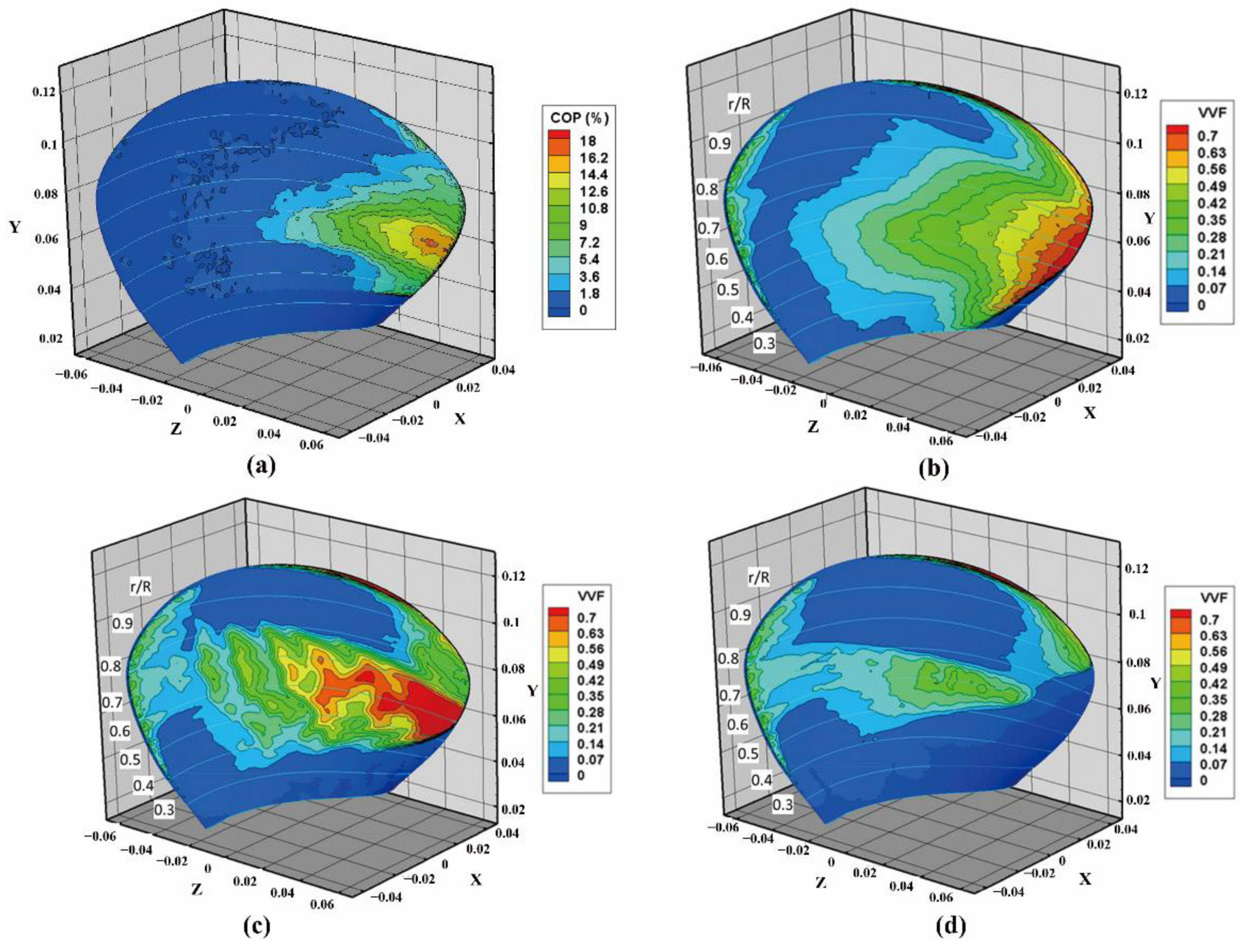
2.2. Flow-Field Characteristics
2.2.1. Cavitation
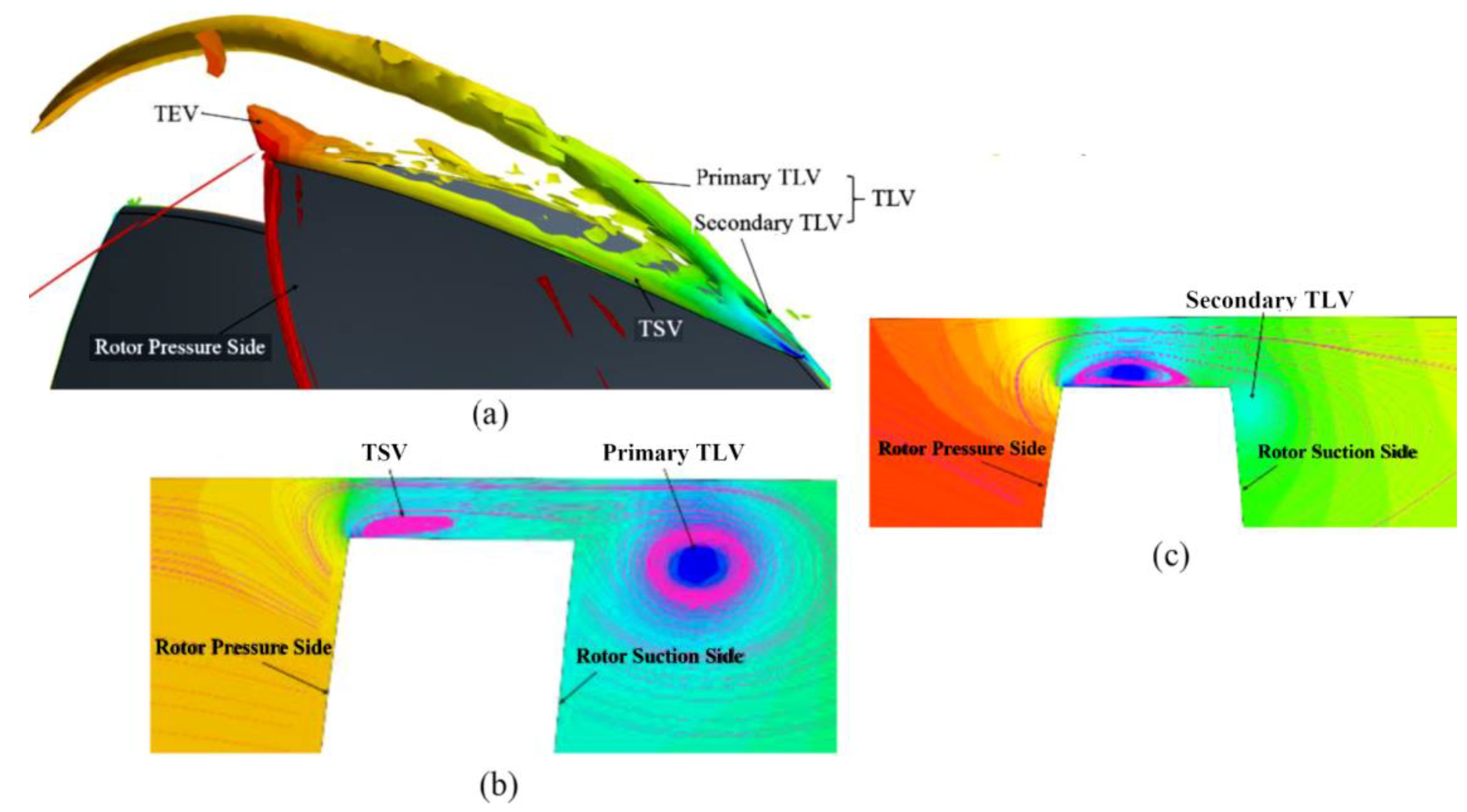
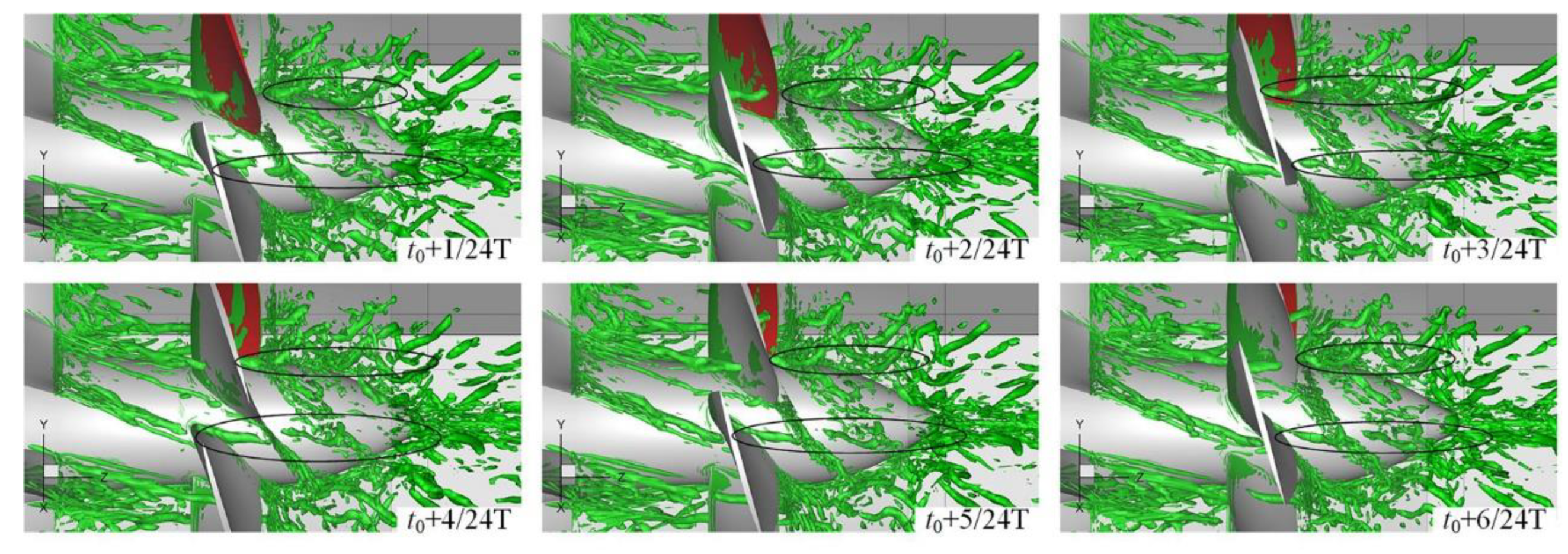
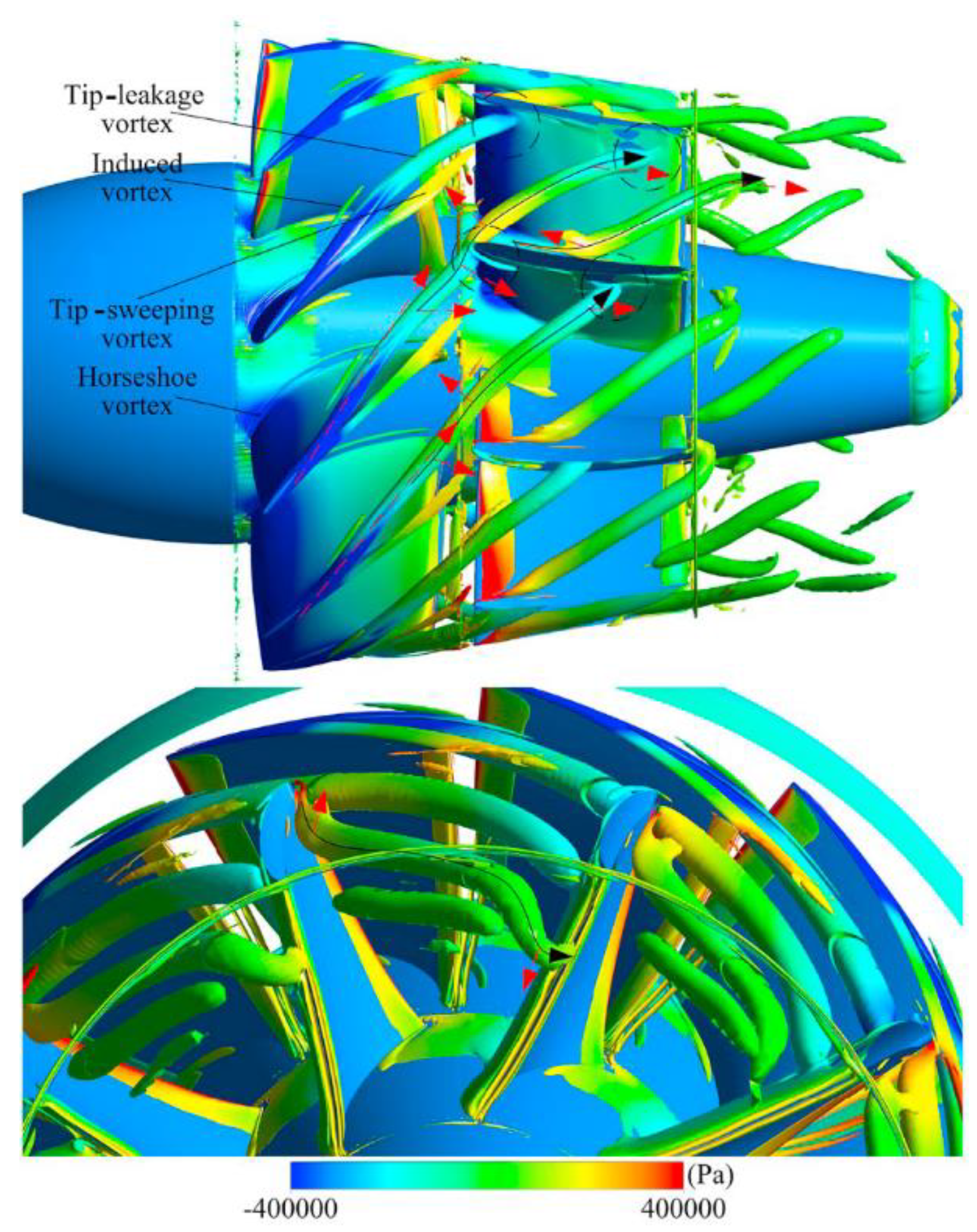
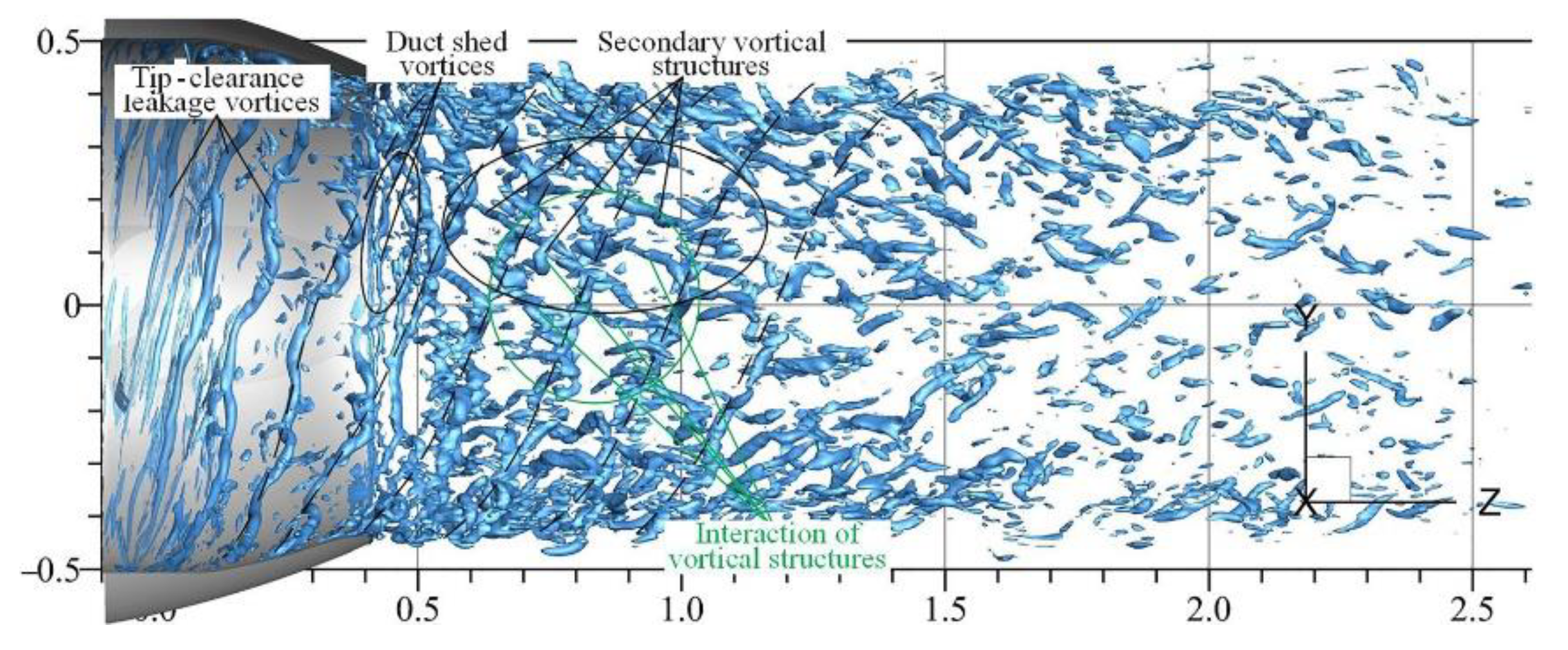
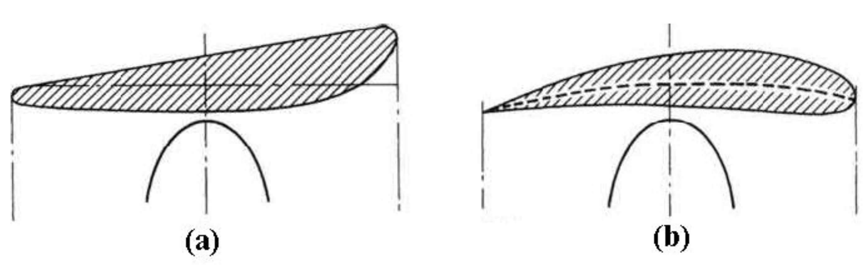
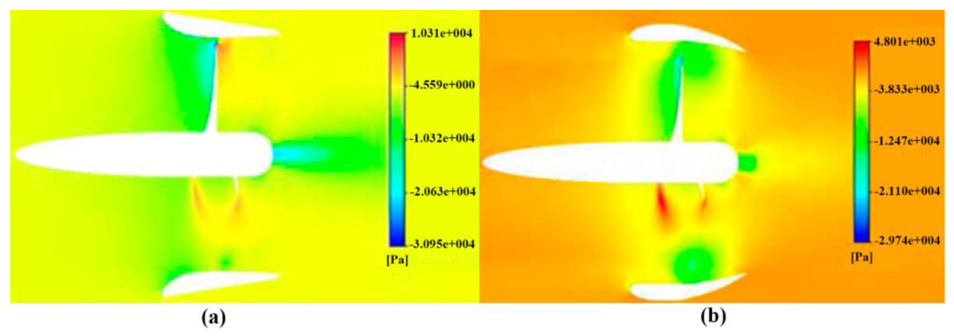
2.2.2. Vortex
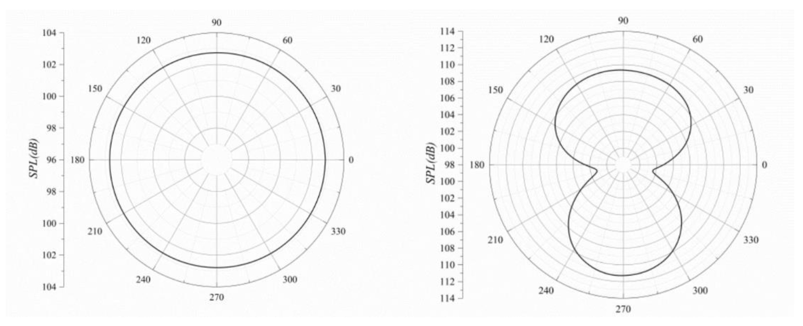
2.3. Noise Characteristics
3. Design Method and Optimization
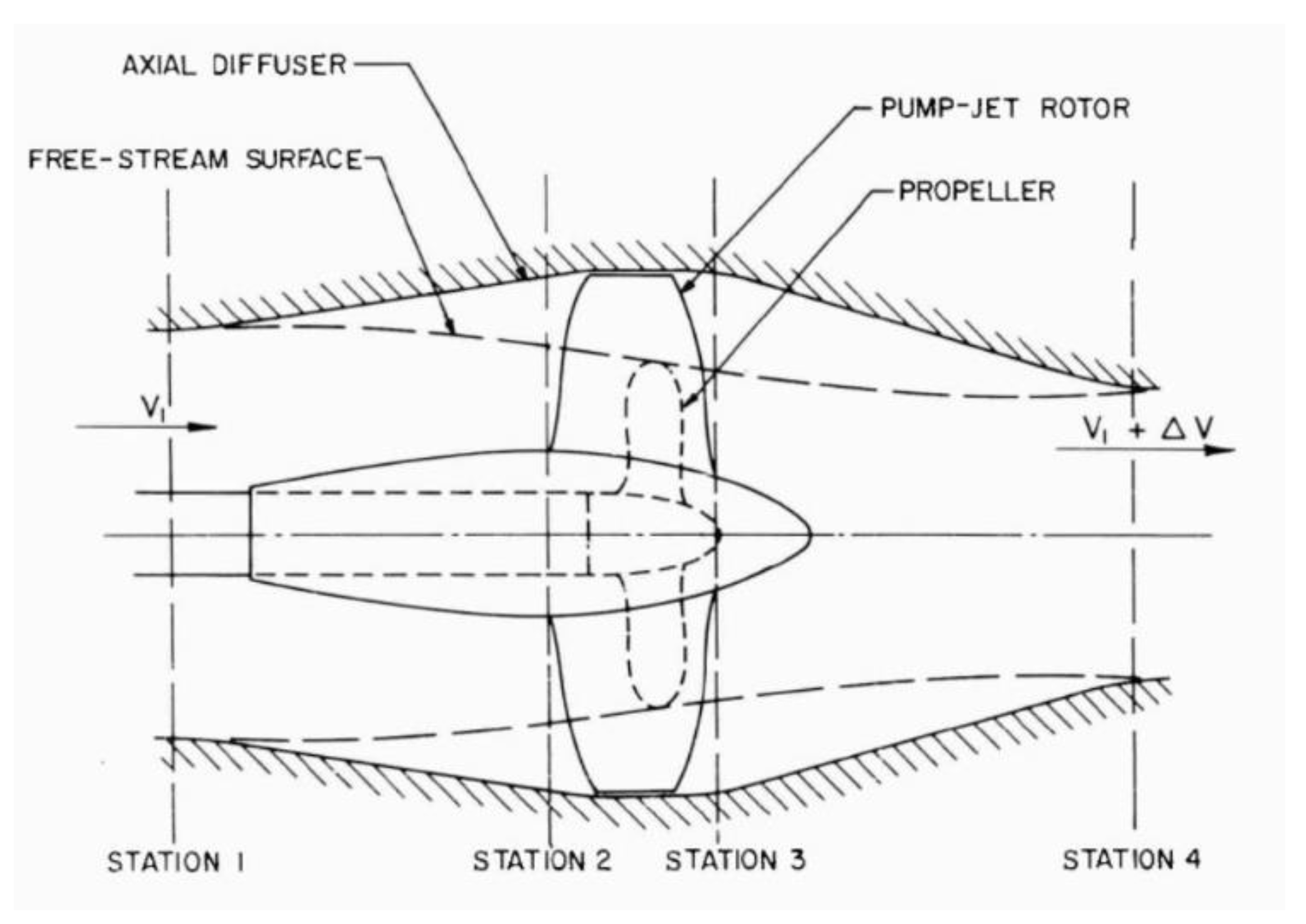
3.1. Design Principle of Pump-Jet
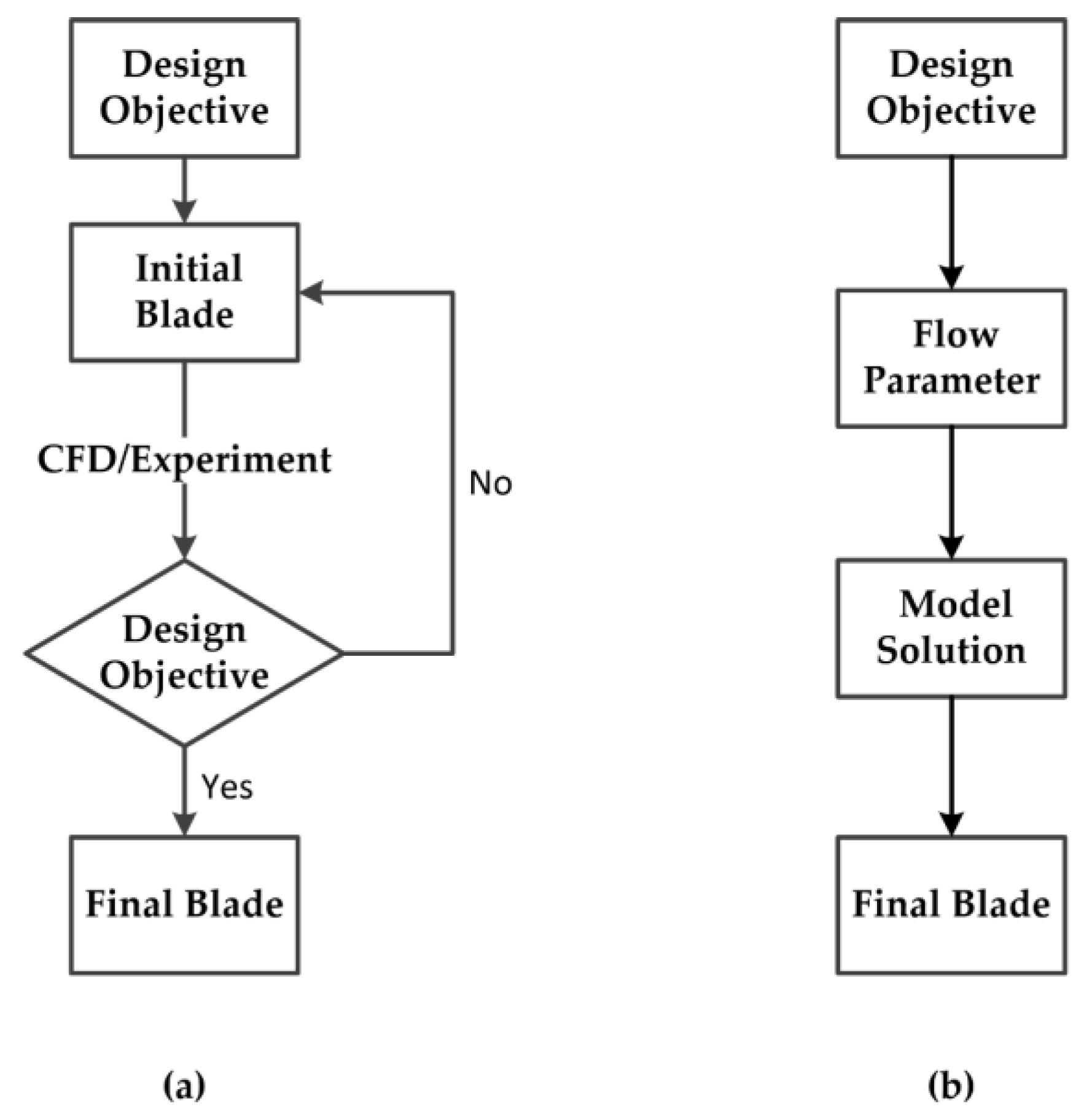
3.2. Direct Design Method
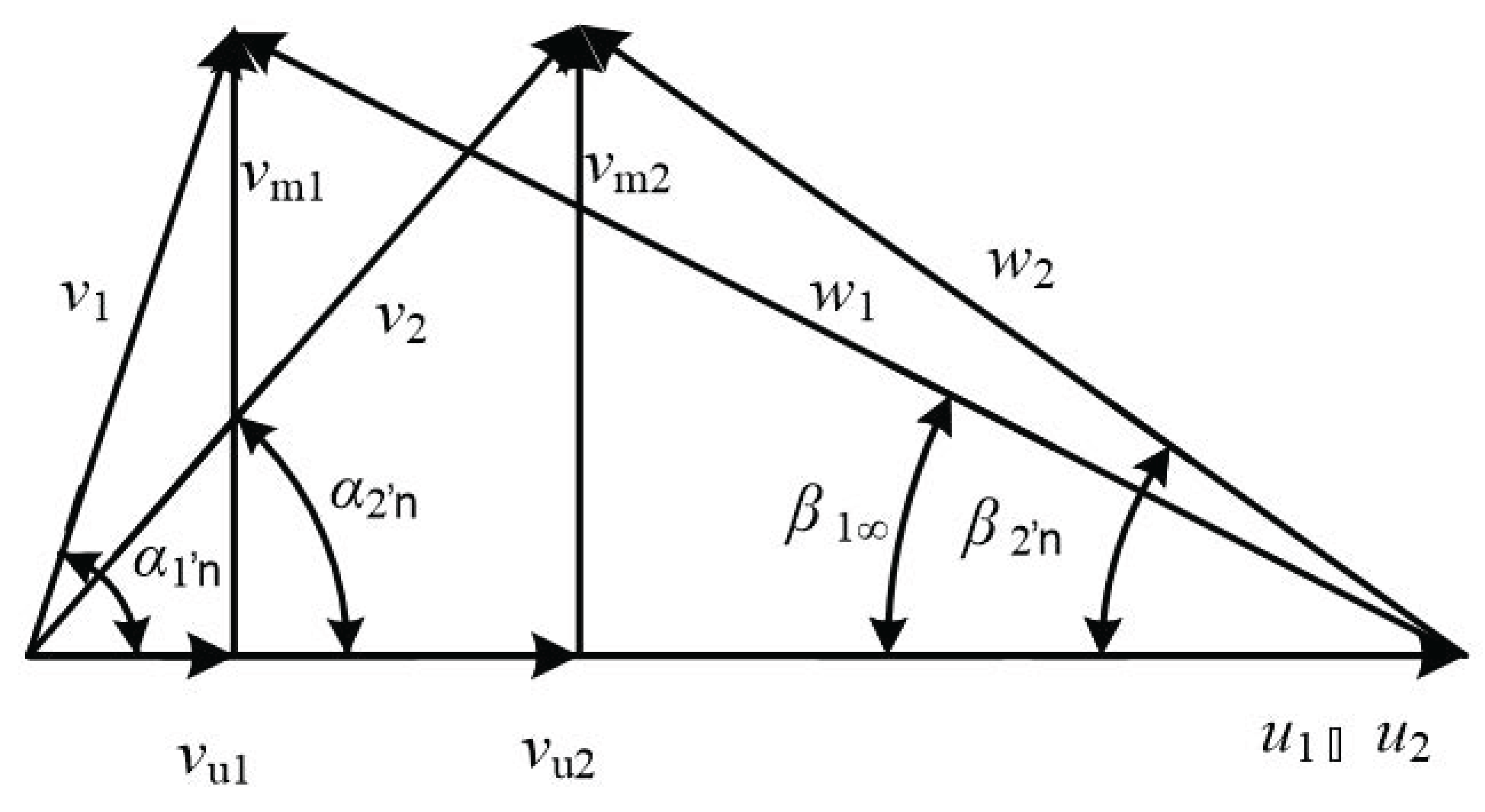
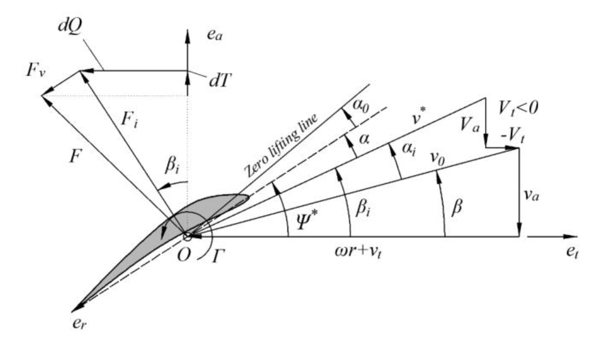
3.2.1. Lifting Design Method
- The flow in the rotor is regarded as potential flow, and there is no radial velocity component;
- The distribution of velocity loop is constant along the radius;
- There is no induced velocity in the axial direction.
3.2.2. Lifting-Line Method
- (1)
- The fluid is regarded as ideally incompressible;
- (2)
- The inflow is treated as steady and axisymmetric;
- (3)
- The rotor wake is regarded as non-contracting, and its influence on the shape of the vortex is not considered;
- (4)
- The radial induced speed is not considered;
- (5)
- It is assumed that the circulation at the hub diameter is 0, but for the rotor with a larger hub, a later correction is required.
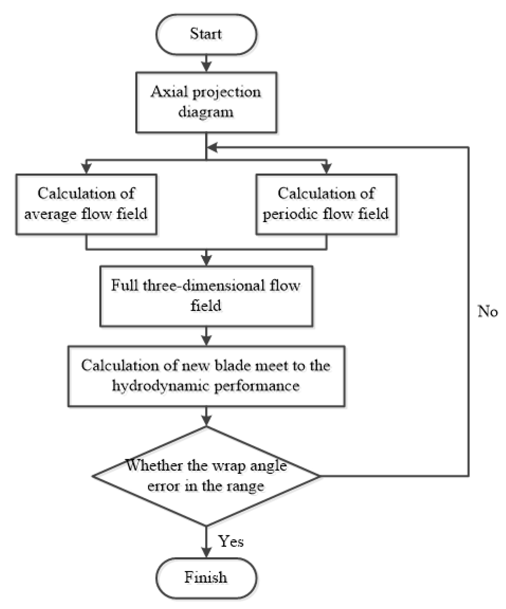
3.3. Inverse Design Method
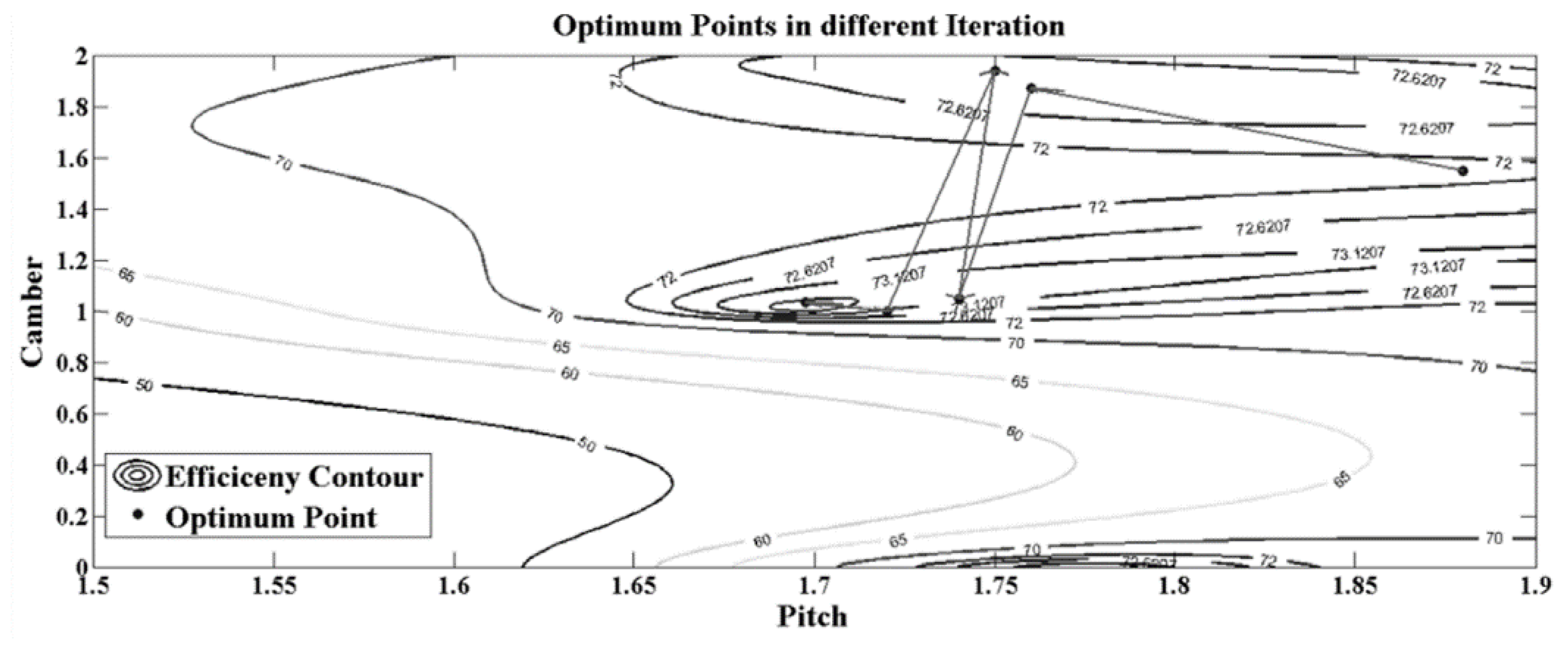
3.4. Optimization
4. Conclusions and Challenge
5. Emerging Possibilities and Prospects
Author Contributions
Funding
Institutional Review Board Statement
Informed Consent Statement
Data Availability Statement
Conflicts of Interest
References
- The Navy Unmanned Undersea Vehicle (UUV) Master Plan. 2004. Available online: https://apps.dtic.mil/sti/citations/ADA511748 (accessed on 10 September 2022).
- United States Navy. Autonomous Undersea Vehicle Requirement for 2025; United States Department of Defense: Commonwealth of Virginia, VA, USA, 2016.
- Renilson, M. Submarine Hydrodynamics; Springer: New York, NY, USA, 2015. [Google Scholar]
- Wan, Y. New Propulsion System for Ships; National Defense Industry Press: Beijing, China, 2014. (In Chinese)
- Wang, Y. Concepts of waterjet propulsion and pumpjet propulsion: Their common characteristics, special characteristics and differences. Chin. J. Ship Res. 2019, 14, 41. [Google Scholar] [CrossRef]
- Wang, C. Special Thrusters and Additional Rectifier Devices; Harbin Engineering University Press: Harbin, China, 2013; pp. 136–137. [Google Scholar]
- Yang, Q.; Wang, Y. Principle and Application of Low Noise Pumpjet Design; Huazhong University of Science and Technology (HUST) Press: Wuhan, China, 2016. [Google Scholar]
- Clarke, G.E. The Choice of Propulsor Design for an Underwater Weapon. 1988. Available online: https://www.researchgate.net/publication/283796945_Propulsion (accessed on 10 September 2022).
- McCormick, B.W.; Elsenhuth, J.J. Design and Performance of Propellers and Pumpjets for Underwater Propulsion. AIAA J. 1963, 1, 2348–2354. [Google Scholar] [CrossRef]
- Okitsugu, F.; Chiang, W.-L. A New Pumpjet Design Theory; Honeywell Inc.: Hopkins, MN, USA, 1988. [Google Scholar]
- Yan, X.; Liang, X.; Ouyang, W.; Liu, Z.; Liu, B.; Lan, J. A review of progress and applications of ship shaft-less rim-driven thrusters. Ocean Eng. 2017, 144, 142–156. [Google Scholar] [CrossRef]
- Lam, W.; Hamil, G.; Song, Y.; Robinson, D.; Raghunathan, S. A review of the equations used to predict the velocity distribution within a ship’s propeller jet. Ocean Eng. 2011, 38, 1–10. [Google Scholar] [CrossRef]
- Liu, Y.; Tan, L.; Wang, B. A Review of Tip Clearance in Propeller, Pump and Turbine. Energies 2018, 11, 2202. [Google Scholar] [CrossRef] [Green Version]
- Wu, S. Research status and future development trend of pump-jet technology. Autom. Appl. 2019, 11. [Google Scholar] [CrossRef]
- Li, H.; Huang, Q.; Pan, G.; Dong, X. Wake instabilities of a pre-swirl stator pump-jet propulsor. Phys. Fluids 2021, 33, 085119. [Google Scholar] [CrossRef]
- Qin, D.; Huang, Q.; Pan, G.; Han, P.; Luo, Y.; Dong, X. Numerical simulation of vortex instabilities in the wake of a preswirl pumpjet propulsor. Phys. Fluids 2021, 33, 055119. [Google Scholar] [CrossRef]
- Yu, H.; Zhang, Z.; Hua, H. Numerical investigation of tip clearance effects on propulsion performance and pressure fluctuation of a pump-jet propulsor. Ocean Eng. 2019, 192, 106500. [Google Scholar] [CrossRef]
- Li, H.; Huang, Q.; Pan, G.; Dong, X. The scale effects on the open water performance of a pump-jet propulsor. J. Mar. Sci. Technol. 2021, 27, 348–367. [Google Scholar] [CrossRef]
- Qin, D.; Huang, Q.; Shi, Y.; Pan, G.; Shi, Y.; Dong, X. Comparison of hydrodynamic performance and wake vortices of two typical types of pumpjet propulsor. Ocean Eng. 2021, 224, 108700. [Google Scholar] [CrossRef]
- Yang, J.; Feng, D.; Liu, L.; Wang, X.; Yao, C. Research on the Performance of Pumpjet Propulsor of Different Scales. J. Mar. Sci. Eng. 2022, 10, 78. [Google Scholar] [CrossRef]
- Ji, Q.; Dong, X.-Q.; Li, W.; Yang, C.-J.; Noblesse, F.; Ji, X.-Q.; Dong, X.-Q.; Li, W.; Yang, C.-J.; Noblesse, F. Numerical Investigation of Tip Geometry on the Tip-clearance Flow Features of a Pump-jet Propulsor. In Proceedings of the VIII International Conference on Computational Methods in Marine Engineering, Göteborg, Sweden, 13–15 May 2019. [Google Scholar]
- Li, F.; Huang, Q.; Pan, G.; Qin, D.; Li, H. Influence of Various Stator Parameters on the Open-Water Performance of Pump-Jet Propulsion. J. Mar. Sci. Eng. 2021, 9, 1396. [Google Scholar] [CrossRef]
- Li, H.; Huang, Q.; Pan, G.; Dong, X.; Li, F. Effects of Blade Number on the Propulsion and Vortical Structures of Pre-Swirl Stator Pump-Jet Propulsors. J. Mar. Sci. Eng. 2021, 9, 1406. [Google Scholar] [CrossRef]
- Li, H.; Huang, Q.; Pan, G.; Dong, X. Assessment of transition modeling for the unsteady performance of a pump-jet propulsor in model scale. Appl. Ocean Res. 2021, 108, 102537. [Google Scholar] [CrossRef]
- Nowruzi, H.; Najafi, A. An experimental and CFD study on the effects of different pre-swirl ducts on propulsion performance of series 60 ship. Ocean Eng. 2019, 173, 491–509. [Google Scholar] [CrossRef]
- Motallebi-Nejad, M.; Bakhtiari, M.; Ghassemi, H.; Fadavie, M. Numerical analysis of ducted propeller and pumpjet propulsion system using periodic computational domain. J. Mar. Sci. Technol. 2017, 22, 559–573. [Google Scholar] [CrossRef]
- Suryanarayana, C.; Satyanarayana, B.; Ramji, K.; Saiju, A. Experimental evaluation of pumpjet propulsor for an axisymmetric body in wind tunnel. Int. J. Nav. Arch. Ocean Eng. 2010, 2, 24–33. [Google Scholar] [CrossRef] [Green Version]
- Suryanarayana, C.; Satyanarayana, B.; Ramji, K. Performance evaluation of an underwater body and pumpjet by model testing in cavitation tunnel. Int. J. Nav. Archit. Ocean. Eng. 2010, 2, 57–67. [Google Scholar] [CrossRef] [Green Version]
- Suryanarayana, C.; Satyanarayana, B.; Ramji, K.; Rao, M.N. Cavitation studies on axi-symmetric underwater body with pumpjet propulsor in cavitation tunnel. Int. J. Nav. Arch. Ocean Eng. 2010, 2, 185–194. [Google Scholar] [CrossRef]
- Shi, S.; Tang, W.; Huang, X.; Dong, X.; Hua, H. Experimental and numerical investigations on the flow-induced vibration and acoustic radiation of a pump-jet propulsor model in a water tunnel. Ocean Eng. 2022, 258, 111736. [Google Scholar] [CrossRef]
- Xin-Guo, D.; Jian-Guo, L.; Yuan-Xing, D.; Wei, S.U. Marine Design and Research Institute of China, Science and Technology on Water Jet Propulsion Laboratory. 2000. Available online: http://www.cnki.com.cn/Article/CJFDTotal-HYGC201905014.htm (accessed on 10 September 2022).
- Shirazi, A.T.; Nazari, M.R.; Manshadi, M.D. Numerical and experimental investigation of the fluid flow on a full-scale pump jet thruster. Ocean Eng. 2019, 182, 527–539. [Google Scholar] [CrossRef]
- Hou, X.; Guo, S.; Shi, L.; Xing, H.; Liu, Y.; Liu, H.; Hu, Y.; Xia, D.; Li, Z. Hydrodynamic Analysis-Based Modeling and Experimental Verification of a New Water-Jet Thruster for an Amphibious Spherical Robot. Sensors 2019, 19, 259. [Google Scholar] [CrossRef] [PubMed] [Green Version]
- Villa, D.; Gaggero, S.; Tani, G.; Viviani, M. Numerical and Experimental Comparison of Ducted and Non-Ducted Propellers. J. Mar. Sci. Eng. 2020, 8, 257. [Google Scholar] [CrossRef] [Green Version]
- Luquet, R.; Bellevre, D.; Fréchou, D.; Perdon, P.; Guinard, P. Design and model testing of an optimized ducted marine current turbine. Int. J. Mar. Energy 2013, 2, 61–80. [Google Scholar] [CrossRef]
- Bhattacharyya, A.; Steen, S. Propulsive factors in waves: A comparative experimental study for an open and a ducted propeller. Ocean Eng. 2014, 91, 263–272. [Google Scholar] [CrossRef]
- Najafi, A.; Nowruzi, H.; Hashemi, S.A. The effects of pre-swirl ducts on the propulsion performance of conventional ship: An experimental study. J. Braz. Soc. Mech. Sci. Eng. 2018, 40, 552. [Google Scholar] [CrossRef]
- Wang, C.; Weng, K.; Guo, C.; Gu, L. Prediction of hydrodynamic performance of pump propeller considering the effect of tip vortex. Ocean Eng. 2018, 171, 259–272. [Google Scholar] [CrossRef]
- Jian, H.; Kaiqiang, W.; Chao, W.; Lang, G.; Chunyu, G. Prediction of hydrodynamic performance of pump jet propulsor considering the effect of gap flow model. Ocean Eng. 2021, 233, 109162. [Google Scholar] [CrossRef]
- Wang, C.; Weng, K.; Guo, C.; Chang, X.; Gu, L. Analysis of influence of duct geometrical parameters on pump jet propulsor hydrodynamic performance. J. Mar. Sci. Technol. 2019, 25, 640–657. [Google Scholar] [CrossRef]
- Yang, J.; Feng, D.; Zhang, H. Numerical simulation of pump-jet propulsor and analysis of scale effect. Shipbuild. China 2020, 61, 91–99. [Google Scholar]
- Sun, M.-Y.; Dong, X.; Yang, C. Numerical simulation and analysis of hydrodynamic scale effect of pump-jet propulsor. J. Unmanned Undersea Syst. 2020, 28, 538–546. [Google Scholar] [CrossRef]
- Wang, J.; Cheng, H.; Xu, S.; Ji, B.; Long, X. Performance of cavitation flow and its induced noise of different jet pump cavitation reactors. Ultrason. Sonochem. 2019, 106, 215–225. [Google Scholar] [CrossRef] [PubMed]
- Ebrahimi, A.; Razaghian, A.; Tootian, A.; Seif, M. An experimental investigation of hydrodynamic performance, cavitation, and noise of a normal skew B-series marine propeller in the cavitation tunnel. Ocean Eng. 2021, 238, 109739. [Google Scholar] [CrossRef]
- Shi, Y.; Pan, G.; Wang, P.; Du, X. Numerical simulation of cavitation characteristics of a pump-jet propeller. J. Shanghai Jiao Tong Univ. 2014, 48, 1059–1064. [Google Scholar] [CrossRef]
- Pan, G.; Lu, L.; Sahoo, P.K. Numerical simulation of unsteady cavitating flows of pumpjet propulsor. Ships Offshore Struct. 2015, 11, 64–74. [Google Scholar] [CrossRef]
- Sun, Y.; Peng, H.; Liu, W.; Guo, J.; Guo, Y. Comparison of the hydrodynamic performance of front and rear-stator pump-jet propulsors in an oblique wake under the cavitation condition. Phys. Fluids 2022, 34, 033317. [Google Scholar] [CrossRef]
- Qiu, C.; Huang, Q.; Pan, G.; Shi, Y.; Dong, X. Numerical simulation of hydrodynamic and cavitation performance of pumpjet propulsor with different tip clearances in oblique flow. Ocean Eng. 2020, 209, 107285. [Google Scholar] [CrossRef]
- Asnaghi, A.; Svennberg, U.; Bensow, R.E. Numerical and experimental analysis of cavitation inception behaviour for high-skewed low-noise propellers. Appl. Ocean Res. 2018, 79, 197–214. [Google Scholar] [CrossRef]
- Zhao, M.-S.; Zhao, W.-W.; Wan, D.-C. Numerical simulations of propeller cavitation flows based on OpenFOAM. J. Hydrodyn. 2020, 32, 1071–1079. [Google Scholar] [CrossRef]
- Lee, Y.-H.; Yang, C.-Y.; Chow, Y.-C. Evaluations of the outcome variability of RANS simulations for marine propellers due to tunable parameters of cavitation models. Ocean Eng. 2021, 226, 108805. [Google Scholar] [CrossRef]
- Zhang, H.; Zang, J.; Shi, W.; Zhang, D. Analysis of the Formation Mechanism and Evolution of the Perpendicular Cavitation Vortex of Tip Leakage Flow in an Axial-Flow Pump for Off-Design Conditions. J. Mar. Sci. Eng. 2021, 9, 1045. [Google Scholar] [CrossRef]
- Zhang, H.; Zang, J.; Zhang, D.; Shi, W.; Shen, J. Analysis of the Formation Mechanism of Secondary Tip Leakage Vortex (S-TLV) in an Axial Flow Pump. Machines 2022, 10, 41. [Google Scholar] [CrossRef]
- You, D.; Mittal, R.; Wang, M.; Moin, P. Computational Methodology for Large-Eddy Simulation of Tip-Clearance Flows. AIAA J. 2004, 42, 271–279. [Google Scholar] [CrossRef]
- Li, H.; Pan, G.; Huang, Q.; Shi, Y. Numerical Prediction of the Pumpjet Propulsor Tip Clearance Vortex Cavitation in Uniform Flow. J. Shanghai Jiaotong Univ. 2019, 25, 352–364. [Google Scholar] [CrossRef]
- Tan, D.; Li, Y.; Wilkes, I.; Vagnoni, E.; Miorini, R.L.; Katz, J. Experimental Investigation of the Role of Large Scale Cavitating Vortical Structures in Performance Breakdown of an Axial Waterjet Pump. J. Fluids Eng. 2015, 137, 111301. [Google Scholar] [CrossRef]
- Han, C.-Z.; Xu, S.; Cheng, H.-Y.; Ji, B.; Zhang, Z.-Y. LES method of the tip clearance vortex cavitation in a propelling pump with special emphasis on the cavitation-vortex interaction. J. Hydrodyn. 2020, 32, 1212–1216. [Google Scholar] [CrossRef]
- Peng, X.-X.; Zhang, L.-X.; Wang, B.-L.; Xu, L.-H.; Song, M.-T.; Cao, Y.-T.; Liu, Y.-W.; Hong, F.-W.; Yan, K. Study of tip vortex cavitation inception and vortex singing. J. Hydrodyn. 2019, 31, 1170–1177. [Google Scholar] [CrossRef]
- Lu, L.; Gao, Y.; Li, Q.; Du, L. Numerical investigations of tip clearance flow characteristics of a pumpjet propulsor. Int. J. Nav. Arch. Ocean Eng. 2018, 10, 307–317. [Google Scholar] [CrossRef]
- Cheng, H.-Y.; Ji, B.; Long, X.-P.; Huai, W.-X.; Farhat, M. A review of cavitation in tip-leakage flow and its control. J. Hydrodyn. 2021, 33, 226–242. [Google Scholar] [CrossRef]
- Li, H.; Huang, Q.; Pan, G.; Dong, X.; Li, F. An investigation on the flow and vortical structure of a pre-swirl stator pump-jet propulsor in drift. Ocean Eng. 2022, 250, 111061. [Google Scholar] [CrossRef]
- Li, H.; Pan, G.; Huang, Q. Transient analysis of the fluid flow on a pumpjet propulsor. Ocean Eng. 2019, 191, 106520. [Google Scholar] [CrossRef]
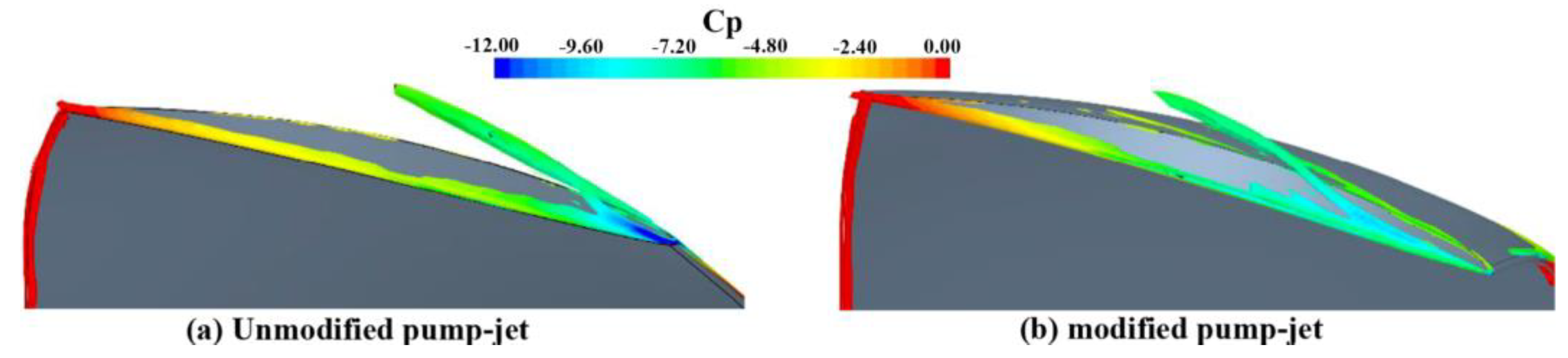
- Ji, X.-Q.; Dong, X.-Q.; Yang, C.-J. Attenuation of the Tip-Clearance Flow in a Pump-Jet Propulsor by Thickening and Raking the Tips of Rotor Blades: A Numerical Study. Appl. Ocean Res. 2021, 113, 102723. [Google Scholar] [CrossRef]
- Kai, Z.; Ye, J. Research on the tip vortex control effect and calculation method of pump jet thruster based on groove structure. Ship Sci. Technol. 2020, 42, 57–62. [Google Scholar] [CrossRef]
- Muscari, R.; Di Mascio, A.; Verzicco, R. Modeling of vortex dynamics in the wake of a marine propeller. Comput. Fluids 2013, 73, 65–79. [Google Scholar] [CrossRef]
- Ahmed, S.; Croaker, P.; Doolan, C.J. On the instability mechanisms of ship propeller wakes. Ocean Eng. 2020, 213, 107609. [Google Scholar] [CrossRef]
- Li, H.; Huang, Q.; Pan, G. Investigation on the Propulsion of a Pump-Jet Propulsor in an Effective Wake. J. Fluids Eng. 2022, 144, 051205. [Google Scholar] [CrossRef]
- Li, H.; Huang, Q.; Pan, G.; Dong, X. The transient prediction of a pre-swirl stator pump-jet propulsor and a comparative study of hybrid RANS/LES simulations on the wake vortices. Ocean Eng. 2020, 203, 107224. [Google Scholar] [CrossRef]
- Qin, D.; Huang, Q.; Pan, G.; Shi, Y.; Han, P.; Dong, X. Effect of the duct and the pre-swirl stator on the wake dynamics of a pre-swirl pumpjet propulsor. Ocean Eng. 2021, 237, 109620. [Google Scholar] [CrossRef]
- Felli, M.; Camussi, R.; DI Felice, F. Mechanisms of evolution of the propeller wake in the transition and far fields. J. Fluid Mech. 2011, 682, 5–53. [Google Scholar] [CrossRef] [Green Version]
- Wolf, C.C.; Schwarz, C.; Kaufmann, K.; Gardner, A.D.; Michaelis, D.; Bosbach, J.; Schanz, D.; Schröder, A. Experimental study of secondary vortex structures in a rotor wake. Exp. Fluids 2019, 60, 175. [Google Scholar] [CrossRef]
- Ri, B.; Jingfeng, G.; Sheng, Z.; Mingxing, Y.; Qing, W.; Chun, L. Research Status of Numerical Simulation Meth-od for Hydrodynamic Noise of Pump-jet Propulsor. Ship Electron. Eng. 2020, 40, 180–183. [Google Scholar] [CrossRef]
- Goldstein, M.E. A generalized acoustic analogy. J. Fluid Mech. 2003, 488, 315–333. [Google Scholar] [CrossRef] [Green Version]
- Ffowcs Williams, J.E.; Hawkings, D.L. Sound Generation by Turbulence and Surfaces in Arbitrary Motion. Philos. Trans. R. Soc. London. Ser. A Math. Phys. Sci. 1969, 264, 321–342. Available online: https://www.jstor.org/stable/73790 (accessed on 10 September 2022).
- Powell, A. Theory of Vortex Sound. J. Acoust. Soc. Am. 1964, 36, 177–195. [Google Scholar] [CrossRef]
- Li, H.; Liu, C.; Wu, F.; Chen, C. A review of the progress for computational methods of hydrodynamic noise. Chin. J. Ship Res. 2016, 11, 72–89. [Google Scholar]
- Sai, A.; Xuanmin, D.; Wei, F. A review of the progress for mechanism and computational method of underwater contour-rotation propeller flow-induced noise. J. Appl. 2020, 39. [Google Scholar] [CrossRef]
- Huang, X.; Shi, S.; Su, Z.; Rao, Z.; Hua, H. Vibro-acoustic responses of a pump-jet under distributed unsteady hydrodynamic forces. J. Vib. Shock. 2021, 40, 89–94. [Google Scholar] [CrossRef]
- Du, X.; Liu, C.; Zhang, X.; Fu, K. Numerical Analysis of Flow Noise Characteristics of Pump-jet Propeller Based on Different Turbulence Models. OCEANS Marseille 2019, 1–8. [Google Scholar] [CrossRef]
- Su, Z.; Shi, S.; Huang, X.; Rao, Z.; Hua, H. Effects of the duct on the vibro-acoustic characteristics of the pump-jet–shaft–submarine system under pump-jet excitation. Ocean Eng. 2022, 254, 111327. [Google Scholar] [CrossRef]
- Huang, X.; Shi, S.; Su, Z.; Tang, W.; Hua, H. Reducing underwater radiated noise of a SUBOFF model propelled by a pump-jet without tip clearance: Numerical simulation. Ocean Eng. 2021, 243, 110277. [Google Scholar] [CrossRef]
- Sun, Y.; Liu, W.; Li, T.-Y. Numerical investigation on noise reduction mechanism of serrated trailing edge installed on a pump-jet duct. Ocean Eng. 2019, 191, 106489. [Google Scholar] [CrossRef]
- Qin, D.; Pan, G.; Lee, S.; Huang, Q.; Shi, Y. Underwater radiated noise reduction technology using sawtooth duct for pumpjet propulsor. Ocean Eng. 2019, 188, 106228. [Google Scholar] [CrossRef]
- Shen, Y.; Hu, P.; Jin, S.; Wei, Y.; Lan, R.; Zhuang, S.; Zhu, H.; Cheng, S.; Chen, J.; Wang, D.; et al. Design of Novel Shaftless Pump-Jet Propulsor for Multi-Purpose Long-Range and High-Speed Autonomous Underwater Vehicle. IEEE Trans. Magn. 2016, 52, 1–4. [Google Scholar] [CrossRef]
- Cao, Y.; Wang, Y.; Jin, S. Propulsive performance optimizing of waterjet. J. Wu Han Univ. Technol. 2015, 39, 211–215. [Google Scholar] [CrossRef]
- John, C. Marine Propellers and Propulsion. London, UK, 2018. Available online: https://www.sciencedirect.com/book/9780750681506/marine-propellers-and-propulsion#book-description (accessed on 10 September 2022).
- Station, C.; Virginia, A. A Method for the Design of Pumpjet. 1964. Available online: https://www.sema-ticscholar.org/paper/A-METHOD-FOR-THE-DESIGN-OF-PUMPJETS-Henderson-McMahon/b9318e80c6530ebe5f67c673051e8d98824f22e7 (accessed on 10 September 2022).
- Peng, Y.; Wang, Y.; Liu, C.; Yi, W. Comparative analysis of the hydrodynamic performance of front-stator and rear-stator pump-jets. J. Harbin Eng. Univ. 2019, 40, 132–140. [Google Scholar] [CrossRef]
- Donyavizadeh, N.; Ghadimi, P. Efficacy Analysis of Thickness and Camber Size of Cross Section of the Stator on Hydrodynamic Parameters in Linear Jet Propulsion System. Math. Probl. Eng. 2020, 2020, 5861948. [Google Scholar] [CrossRef]
- Hu, J.; Huang, N.; Hu, Y. Performance comparison of accelerating duct and decelerating duct. J. Beijing Univ. Aeronaut. Astronaut. 2017, 43, 241–252. [Google Scholar] [CrossRef]
- Razaghian, A.H.; Ghassemi, H. Numerical analysis of the hydrodynamic characteristics of the accelerating and decelerating ducted propeller. Zesz. Nauk. Akad. Mor. W Szczec. 2016, 119, 42–53. [Google Scholar] [CrossRef]
- Bontempo, R.; Manna, M. Performance analysis of ducted marine propellers. Part II—Accelerating duct. Appl. Ocean Res. 2018, 75, 153–164. [Google Scholar] [CrossRef]
- Bontempo, R.; Cardone, M.; Manna, M. Performance analysis of ducted marine propellers. Part I—Decelerating duct. Appl. Ocean Res. 2016, 58, 322–330. [Google Scholar] [CrossRef]
- Huang, Q.; Li, H.; Pan, G.; Dong, X. Effects of duct parameter on pump-jet propulsor unsteady hydrodynamic performance. Ocean Eng. 2020, 221, 108509. [Google Scholar] [CrossRef]
- Xin-Guo, D.; Hui, L.; Peng, Y.; Li, N. Numerical Analysis of Infl uence of Duct Inclination Angle and Camber on Interaction between Pump Jet and Hull. Ship Boat 2020, 31, 11–20. [Google Scholar] [CrossRef]
- Bonaiuti, D.; Zangeneh, M. On the Coupling of Inverse Design and Optimization Techniques for the Multiobjective, Multipoint Design of Turbomachinery Blades. J. Turbomach. 2009, 131, 021014. [Google Scholar] [CrossRef]
- Lu, L. Reaseach on Design and Flow Field Characteristic of the Pumpjet Propulsor; Northwestern Polytechnical University: Xi’an, China, 2016. [Google Scholar]
- Liu, Y. Study on Design Method of Pump Jet Thruster for Underwater Vehicles; Harbin Engineering University: Harbin, China, 2013. [Google Scholar]
- Zhang, M.; Lin, R.; Wang, Y.; Lin, B. 3-D inverse design of pumpjet and comparison with opening water performance of original propeller. J. Harbin Eng. Univ. 2017, 38, 690–696. [Google Scholar] [CrossRef]
- Zhang, M.; Yu, W.; Chen, Z. 3D Inverse Design of Pumpjet and Study on the Influence of Blade Profile. In Proceedings of the 2019 2nd International Conference on Mechanical Engineering, Industrial Materials and Industrial Electronics (MEIMIE 2019), Dalian, China, 29–30 March 2019. [Google Scholar]
- Jin, S.; Zhu, H.; Wang, D.; Wei, Y. Research on the global parameters selection and design of pumpjet of underwater vehicle. J. Harbin Eng. Univ. 2018, 39, 851–856. [Google Scholar] [CrossRef]
- Xingfan, G. Manual of Modern Pump Technology; Aerospace Publisher: Zhenjiang, China, 1995. [Google Scholar]
- Zhou, Y.; Wang, L.; Yuan, J.; Luo, W.; Fu, Y.; Chen, Y.; Wang, Z.; Xu, J.; Lu, R. Comparative Investigation on Hydrodynamic Performance of Pump-Jet Propulsion Designed by Direct and Inverse Design Methods. Mathematics 2021, 9, 343. [Google Scholar] [CrossRef]
- Aziz, M.; Tayarani, M.H.N. An adaptive memetic Particle Swarm Optimization algorithm for finding large-scale Latin hypercube designs. Eng. Appl. Artif. Intell. 2014, 36, 222–237. [Google Scholar] [CrossRef]
- Wu, C.; Lu, Y.; Liu, S.; Li, Z.; Gu, Z.; Shao, W.; Li, C. Research on Optimization Design of Fully Parameterized Pump-Jet Propulsion. J. Mar. Sci. Eng. 2022, 10, 766. [Google Scholar] [CrossRef]
- Gypa, I.; Jansson, M.; Wolff, K.; Bensow, R. Propeller optimization by interactive genetic algorithms and machine learning. Ship Technol. Res. 2021, 1–16. [Google Scholar] [CrossRef]
- Nouri, N.M.; Mohammadi, S.; Zarezadeh, M. Optimization of a marine contra-rotating propellers set. Ocean Eng. 2018, 167, 397–404. [Google Scholar] [CrossRef]
- Chikh, M.A.A.; Belaidi, I.; Khelladi, S.; Hamrani, A.; Bakir, F. Coupling of inverse method and cuckoo search algorithm for multiobjective optimization design of an axial flow pump. Proc. Inst. Mech. Eng. Part A J. Power Energy 2019, 233, 988–1006. [Google Scholar] [CrossRef]
- Qiu, C.; Huang, Q.; Pan, G.; He, X. Multi-path deep learning framework on discrete pressure points to predict velocity field of pump-jet propulsor. Appl. Ocean Res. 2022, 123, 103173. [Google Scholar] [CrossRef]
- Qiu, C.; Huang, Q.; Pan, G.; He, X. Framework for a variational Bayesian convolutional network for velocity field prediction and uncertainty quantification of a pump-jet propulsor. Phys. Fluids 2022, 34, 077109. [Google Scholar] [CrossRef]


| Physical Parameter | Definition |
|---|---|
| Advance Coefficient | |
| Rotating System Thrust Coefficient | |
| Static System Thrust Coefficient | |
| Rotating System Torque Coefficient | |
| Total Thrust Coefficient | |
| Total Torque Coefficient | |
| Propulsion Efficiency |
Publisher’s Note: MDPI stays neutral with regard to jurisdictional claims in published maps and institutional affiliations. |
© 2022 by the authors. Licensee MDPI, Basel, Switzerland. This article is an open access article distributed under the terms and conditions of the Creative Commons Attribution (CC BY) license (https://creativecommons.org/licenses/by/4.0/).
Share and Cite
Zhou, Y.; Pavesi, G.; Yuan, J.; Fu, Y. A Review on Hydrodynamic Performance and Design of Pump-Jet: Advances, Challenges and Prospects. J. Mar. Sci. Eng. 2022, 10, 1514. https://doi.org/10.3390/jmse10101514
Zhou Y, Pavesi G, Yuan J, Fu Y. A Review on Hydrodynamic Performance and Design of Pump-Jet: Advances, Challenges and Prospects. Journal of Marine Science and Engineering. 2022; 10(10):1514. https://doi.org/10.3390/jmse10101514
Chicago/Turabian StyleZhou, Yunkai, Giorgio Pavesi, Jianping Yuan, and Yanxia Fu. 2022. "A Review on Hydrodynamic Performance and Design of Pump-Jet: Advances, Challenges and Prospects" Journal of Marine Science and Engineering 10, no. 10: 1514. https://doi.org/10.3390/jmse10101514