Article

SMURF: A Fully Autonomous Water Surface Cleaning Robot with A Novel Coverage Path Planning Method

1
School of Marine Science and Technology, Northwestern Polytechnical University, Shaanxi 710068, China
2
ORCA-Uboat, Xi’an 710004, China
3
Department of Electronic Engineering, Tsinghua University, Beijing 100080, China
*
Author to whom correspondence should be addressed.
J. Mar. Sci. Eng. 2022, 10(11), 1620; https://doi.org/10.3390/jmse10111620
Submission received: 16 September 2022 / Revised: 16 October 2022 / Accepted: 26 October 2022 / Published: 1 November 2022
(This article belongs to the Special Issue Advances in Marine Vehicles, Automation and Robotics)

Abstract

:
In recent years, more attention has been paid to water surface environment protection. Current water surface waste cleaning mainly relies on manual operations, which are low-efficiency and dangerous. Therefore, in this paper, we design a fully autonomous water surface cleaning robot, SMURF, which achieves high-efficiency water surface cleaning without human operation and adapts to be used in various types of real-world water bodies. In addition, we propose a novel coverage path planning method on water surfaces and an improved nonlinear model predictive controller. The real-world experiment shows that SMURF works well in different kinds of water bodies and achieves much higher efficiency than traditional water surface cleaning methods.

1. Introduction

Marine plastics have severely threatened marine wildlife and caused sustained effects on the whole ecosystem [1]. Recently, much attention has been paid to marine floating plastic monitoring and cleaning to reduce pollution [2,3,4,5]. Besides, as one major source of marine plastics is the plastic waste generated on land and entering the ocean via the inland waterways [6,7], limiting the flux of plastic pollution from river freshwater systems into marine ecosystems is also a key piece in reducing global plastic accumulation in the marine environment [8]. It is essential to clean the floating waste in time in inland waters, coastal areas, and marinas, as shown in Figure 1.
Traditional methods for floating waste cleaning mainly rely on human operations as shown in Figure 2. However, on one hand, collecting wastes on water surfaces manually is tough and dangerous due to the possibilities of accidental drowning and polluted toxic waters [9]. On the other hand, it is low-efficiency to clean up a large water area only relying on human operations.
To mitigate the risk of water surface cleaning for humans and increase cleaning efficiency, autonomous devices can be used to replace the traditional operation mode. Compare to manual operation, water surface cleaning robots can reach places that are dangerous for humans to clean up thoroughly. Besides, a water surface cleaning robot with a high degree of automation can guide, remove, contain, and transport debris without human operation [8], which can increase the cleaning efficiency a lot.
To thoroughly clean all the floating wastes, the cleaning robot needs to cover a whole water surface. Therefore, it is essential to generate a coverage cleaning path to guide the robot. Traditional coverage path planning (CPP) methods like boustrophedon cellular [10] and line-sweep-based decompositions [11] have been proposed for many years. However, unlike the typical CPP for floor-cleaning robots, for water surface cleaning robots, a coverage path needs to be generated under more irregular boundaries with obstacles inside. Besides, the motion characteristics of surface cleaning robots, such as low turning speed, need to be considered in path planning for higher cleaning efficiency.
In this paper, we design a novel autonomous water surface waste cleaning robot, SMURF, which achieves high-efficiency cleaning without any human operation and can be used in various real-world water bodies such as inland waterways, lakes, coastal areas, and marines. To improve the cleaning efficiency, we propose a CPP method for the water surface cleaning robot that can be used in waters with irregular boundaries and obstacles inside. Additionally, we design an improved nonlinear model predictive controller (NMPC) for SMURF to better track the planned path.
The contribution of this paper mainly lies in the following aspects:
  • We design a new robot that achieves fully autonomous water surface cleaning and significantly increases cleaning efficiency.
  • We propose a novel CPP method for water surface cleaning and design an improved NMPC for water surface cleaning robots.
  • We conduct real-world experiments in various water bodies to test the cleaning performance of SMURF.
The detailed composition of this paper is listed as follows: In Section 2, we discuss the related work about water surface robots and coverage path planning. Section 3 shows the hull design, hardware, and working procedure of SMURF. Section 4 introduces the autonomous system of SMURF, and describes our water surface CPP method and the improved NMPC. In Section 5, we conduct experiments for the proposed methods and test the robot in a real-world cleaning scene. Section 6 finally concludes this paper.

2. Related Work

2.1. Water Surface Robot

Recently, water surface robots, also called unmanned surface vehicles (USVs), are applied to various autonomous applications such as transportation, research, and monitoring. The Roboat [12] developed by Wang et al. aims at autonomous transportation using the robot boat in urban waterways, and multiple robot boats can also re-assemble into desired shapes and sizes to execute transportation tasks. Peng et al. [13] develop a USV to achieve hydrographic surveying and charting in nearshore shallow waters. Maawali et al. [14] design a USV for oil spill handling. Shojaei et al. [15] shows the feasibility of using a small USV for built environment management such as structural health monitoring.
Among all the applications of water surface robots, the water surface cleaning robots have attracted a lot of attention from researchers and have been proven to be valuable. Some water surface cleaning robot prototypes have been built [16,17,18,19,20]. Some of the robots mainly rely on manual operations such as remote control [16,17,19], and these robots do not collect floating waste actively. Additionally, Hasany et al. [18] propose an autonomous surface cleaning robotic system capable of navigating small water bodies. The robot has a short working time with a small trash container and is only tested in small water areas like the swimming pool which makes it hard to be used for regular waste cleaning. Chang et al. [20] design a robot for autonomous water quality monitoring and water surface cleaning. The cleaning robot is now assembled without a mechanical design and also remains a demo design.
In conclusion, there are still two shortcomings in current water surface cleaning robots. One is the automation level of the robots is relatively low. The path planning is not mentioned for a complete water area cleaning. The other is that it is hard for the robots to adapt to real-world complex environments, as the water bodies for experiments are simple.

2.2. Coverage Path Planning

Given a region, the CPP problem means planning a path that covers the entire region considering the vehicle’s motion restrictions and sensor’s characteristics, while avoiding passing over obstacles [21]. CPP plays an important role in different kinds of robot autonomous operations. For unmanned aerial vehicles (UAV), CPP can be used in tasks such as surveillance, photogrammetry, and smart farming (for example, pesticide spraying). Cabreira et al. [22] propose an energy-aware spiral CPP algorithm for photogrammetric applications. Aiming at saving energy, the algorithm also sets different optimal speeds for each straight segment. Coombes et al. [23] also consider the influence of the wind in CPP to decrease the total flight time. Besides, Chen et al. [24] propose a clustering-based method for multiple UAVs system CPP tasks. For agriculture field robots, to achieve higher productivity with lower energy consumption in tasks like autonomous harvesting, it is also essential to generate an effective coverage path. Hameed et al. [25] propose an agriculture vehicles 3D CPP approach to minimize energy requirements. Considering the kinematic and operational constraints of agriculture vehicles, Yu et al. [26] propose a CPP approach to minimize the non-working distance. Jeon et al. [27] propose a complete paddy field-coverage path planner for a fully autonomous tillage tractor. For indoor robots, Mao et al. [28] propose a novel strategy of a combined CPP algorithm, which combines the template-based and the heuristic CPP for mobile robots in an indoor environment. Bormann et al. [29] provide open source implementations of six CPP methods and compare the methods using 550 different indoor environment maps. Additionally, Kyaw et al. [30] present a novel approach to solve the CPP problem in complex environments based on the traveling salesman problem and deep reinforcement learning based on the given grid-based maps. For water surface robots, the CPP can be used in tasks of terrain, velocity, water quality, and hydrological measurements [31]. Xu et al. [31] propose a complete coverage neural network (CCNN) algorithm for the CPP of USVs. Zhang et al. [32] present a model based on an improved genetic algorithm to solve the CCPP problem for USV. However, compared to other kinds of robots, the CPP for water surface cleaning robots is still a relatively unexplored area.

3. Water Surface Cleaning Robot Design

In this section, we will briefly introduce the design of SMURF, including hull design, hardware system, and working procedure.

3.1. Hull Design

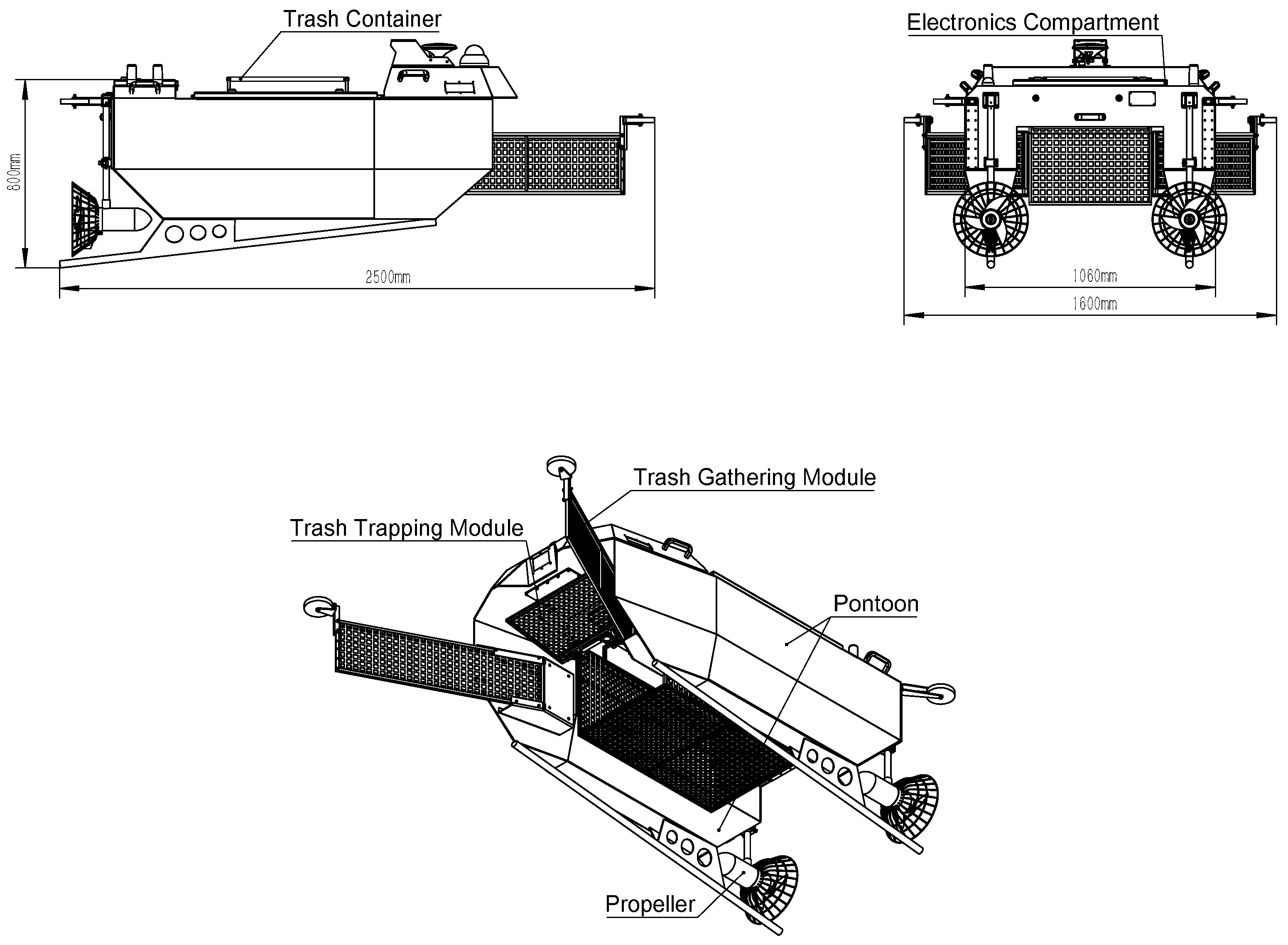
The structure of SMURF mainly contains three parts: the trash collection module in the front, the pontoons on two sides, and the electronics compartment at the back. The technical specifications of SMURF are shown in Table 1.
The hull adopts a two-pontoon construction, which makes SMURF more stable in water waves and is made of aluminum alloy of 3 mm thickness for good corrosion resistance. The electronic compartment achieves a waterproof level of IP67 to ensure that the electronic devices can be prevented from water. The mechanical design of the hull is shown in Figure 3.
The trash collection module in the front consists of three parts: a trash gathering module, a trash trapping module, and a trash container. The trash gathering module is the “arms” of SMURF to significantly improve the trash collection coverage area of SMURF. The mesh “arms” are designed to both gather trash and to make a water current pass through to reduce the water resistance. The trash trapping module is similar to a “door”, which is automatically controlled through an electric motor to switch between the open state and the closed state. When SMURF is moving forward, the “door” will open to collect floating trash. When SMURF is stationary or is moving backward, the “door” will close to prevent the collected trash from flowing out. The state of the trash trapping module is associated with the motion of SMURF to achieve autonomous state switching under different moving states. The mesh trash container is 1 cm 2 in mesh size to reduce water resistance while preventing the trash from flowing out. The trash container is detachable. After cleaning, the trash inside can be dumped conveniently.
SMURF has two electronic propellers symmetrically mounted on the left and right sides at the back. Each propeller has a maximum power of 500W. When two propellers both turn clockwise or anti-clockwise, the SMURF moves forward or backward. When one propeller turns clockwise and the other turns anti-clockwise, the SMURF turns. Therefore, by adjusting the rotation direction and the speed of the two propellers, SMURF can be controlled to move along the curve path.

3.2. Hardware

The hardware system mainly contains the main processor, the communication system, sensors, and the power supply. For the main processor, we adopt the Nvidia Xavier NX embedded processor which contains a GPU and delivers 20 TOPS with a small size and low power. Besides, we adopt an STM32 micro-controller as the auxiliary processor to achieve signal conversion between the main processor and the hardware equipment. The communication module contains a 2.4 G wireless communication system and a 4 G communication system. The 2.4 G wireless communication system enables real-time remote control of SMURF using a remote controller within 2 km in an unobstructed area. The 4 G communication connects SMURF to the Internet to achieve remote control and data monitoring without a distance limitation. For sensors, we use an RGB camera and a 77 GHz millimeter wave (mmWave) radar for environment perception. A real-time kinematic (RTK) enabled global navigation satellite system (GNSS) and a 6-axis inertial measurement unit (IMU) are used to gather the position and pose information of SMURF. For the power supply, considering the discharge rate and the energy density, we adopt a 24 V 140 AH lithium battery to power the propellers and the hardware system. The hardware system of SMURF is shown in Table 2.

3.3. Working Procedure

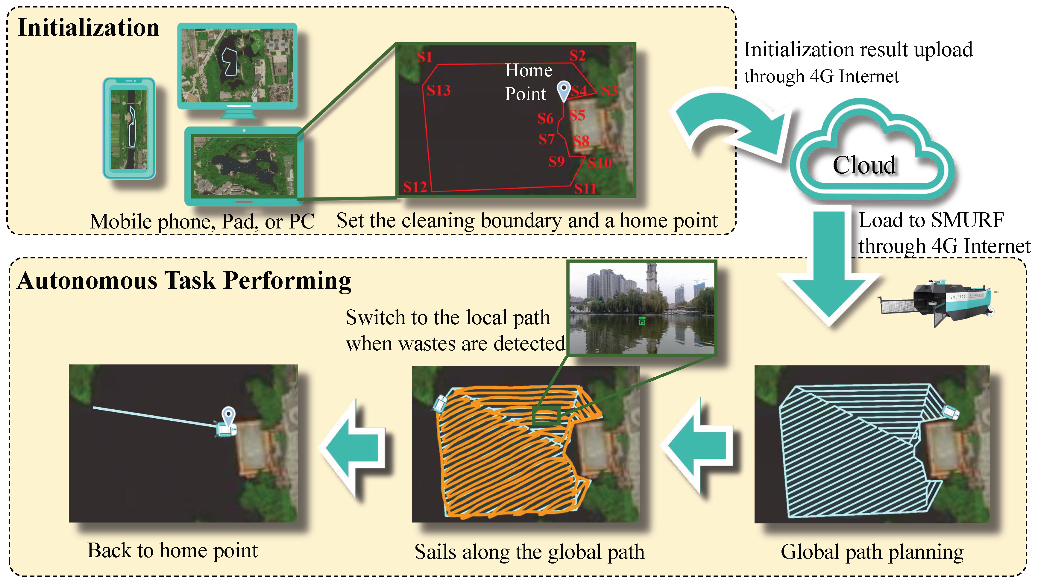
For SMURF, we expect it to achieve fully autonomous cleaning. Therefore, the design of the working procedure is also of vital importance. The working procedure we design is shown in Figure 4. For a new water body, we first need to carry out initialization for one time. During initialization, we need to set a cleaning boundary on the satellite map in an APP on a mobile phone, a PAD, or a PC manually. The boundary can be set by directly marking the boundary points on the satellite map or remotely controlling the SMURF to sail along the boundary to get the boundary point coordinates. After setting a cleaning boundary, a home point also needs to be set to complete the initialization procedure. For each water body, we only need to initialize for one time. After initialization, the cleaning procedure of SMURF will be fully autonomous. Each time the SMURF begins to clean, it will sail along the autonomously planned coverage path for cleaning. If there are multiple cleaning areas, the SMURF will connect multiple areas and cover each area in turn for cleaning. After cleaning all the areas, the SMURF will turn back to the home point autonomously. A whole cleaning task is completed, and the SMURF waits for dumping trash in the trash container and charging.

4. Autonomous System

4.1. Autonomous System Framework

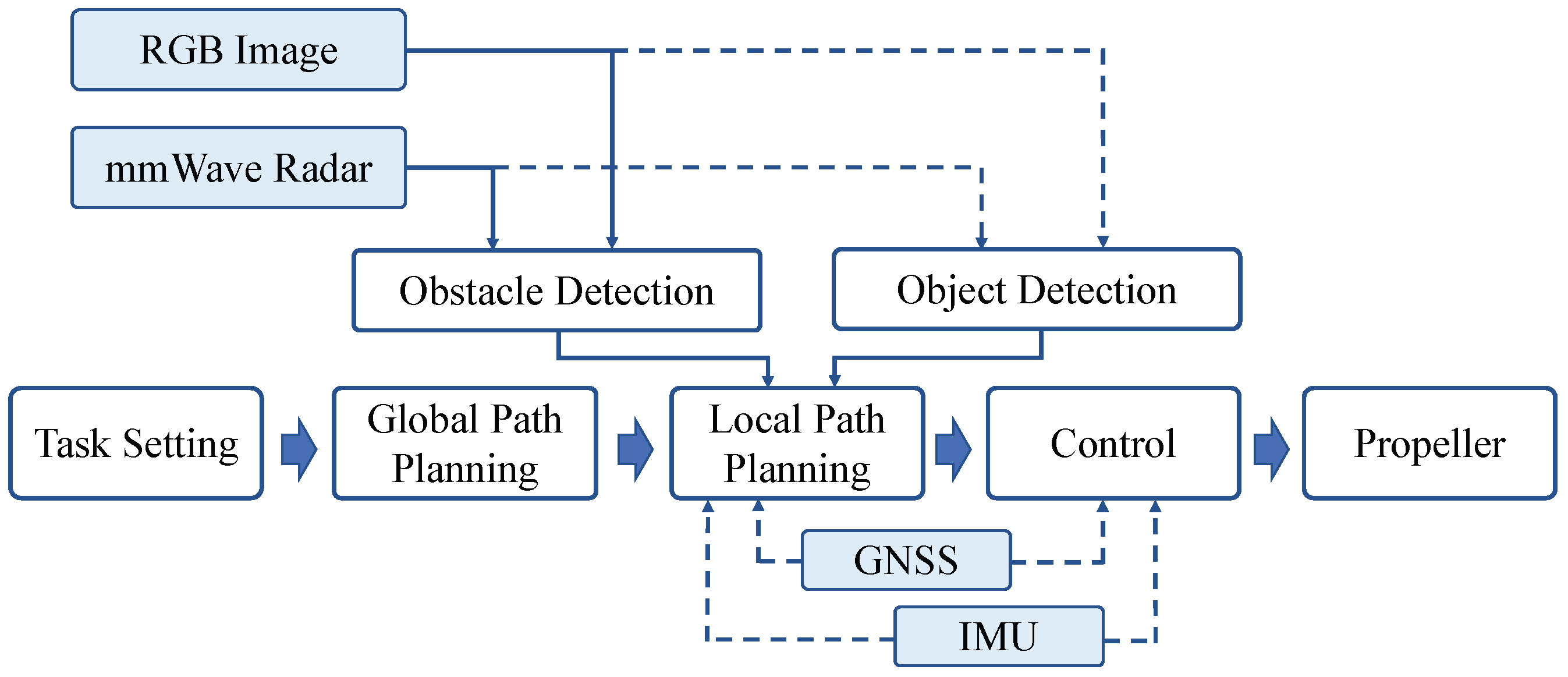
The autonomous system of SMURF is shown in Figure 5. Users will firstly set a cleaning area boundary on the satellite map through a smartphone APP. Based on the boundary, a coverage cleaning path is generated using our global path planning method. The RTK-enabled GNSS and IMU data are fused to provide accurate position and pose information of SMURF. The environment perception of SMURF relies on the fusion of mmWave radar point clouds and RGB images. SMURF is controlled through our improved NMPC controller to sail along the generated path. When there are obstacles on the path that are detected during the task, a local path will be generated to bypass the obstacles [33]. In addition, the SMURF detects floating trash autonomously and collects the trash in time to avoid trash moving. Real-time waste detection relies on our radar-aided visual detection module [34]. As shown in Figure 6, when the trash is detected, the classes, range, and azimuth information of the target will also be sent to the local path planning module to generate a new local path. Then, SMURF will deviate from the current global path to collect waste along the generated local path. When the waste collection is completed, SMURF will continue to cover the water surface along the global path. To avoid the SMURF deviating too far from the global path, we set a maximum deviation with twice the coverage path width. If the SMURF reaches the maximum deviation from the global path, it will go back to the global path until the next time it detects trash.

4.2. Water Surface Coverage Path Planning

When performing water surface cleaning tasks, we first manually mark the boundary points of the cleaning area on the satellite map, which contains the water area. Suppose that in a certain cleaning task, the set of boundary points of the cleaned area is S, and the boundary points of the area included in the set are { N 1 , N 2 , , N m } , where m denotes the number of boundary points. According to the artificial marking sequence of the boundary points, a closed polygonal area can be formed by sequentially connecting the points. Additionally, the area to be cleaned may contain known obstacle areas. The boundary of one obstacle area is also represented as a set of boundary points, which is denoted as A and A = { Q 1 , Q 2 , , Q q } , where q denotes the number of points. The inputs of the proposed CPP method are the boundary point set S of the arbitrary polygon area to be cleaned and the set { A 1 , A 2 , , A r } of r known obstacles’ boundary points as shown in Figure 7, and the final output result is the planned optimal path L. The set L includes a series of path points’ coordinates. We define two kinds of cleaning areas: areas of a regular polygon and irregular polygon. The regular polygon means convex polygon. The irregular polygon means the polygon contains obstacles or the concave polygon.
Different from the common path planning problems of other mobile robots, the CPP in surface cleaning tasks has the following two characteristics:
(1) CPP needs to be performed in an area of any shape and containing any obstacles;
(2) The shortest cleaning path does not mean the highest cleaning efficiency. For surface cleaning, turning will cost a lot of time. Therefore, it is necessary to simultaneously achieve fewer turns and a shorter path.
We define the regional path planning efficiency metric as D, which represents the total time to complete a whole task according to the planning path L:
D ( L ) = l / v + k T ,
where l denotes the total length of the path L, v denotes the average straight speed of the robot, T denotes the average time of turning, and k denotes the number of planned turns. We define the coverage rate ε as the ratio of the covered region to the whole region, δ as the minimum coverage rate, and L as the planned path. Therefore, the CPP problem of a convex polygon can be regarded as
L b e s t = arg L min D ( L ) , s . t . ε > δ
Hence, we propose the water surface coverage path planning (WSCPP) method. The WSCPP includes two situations, hereinafter referred to as Algorithms 1 and 2. Algorithm 1 is suitable for path planning in a regular polygon while Algorithm 2 is suitable for irregular polygons. Details about the two situations are introduced next.
Algorithm 1 The WSCPP algorithm (for regular region).
Input: Regular region with coordinates of boundary points in the region S = { N 1 , N 2 , , N m } , width of single effective cleaning d
Output: Optimal trajectory L b e s t
  1: Define set of trajectories L =
  2: for i = 1 t o m do
  3:       Compute the scan direction parallel to edge line l ( i , 1 ) = N i , N ( i + 1 ) % m
  4:       Generate multiple lines by translating line l ( i , 1 ) by space d until there are no more parallel line intersecting with the region edges. The generated set of lines l ( i , 1 ) , l ( i , 2 ) , , l ( i , n i )
  5:       Define back-and-forth trajectory line set L i =
  6:       for  j = 1 t o n i  do
  7:             Calculate the intersection point set s j between l ( i , j ) and region edges
  8:             if  j % 2 = 0  then
  9:                   Inverse points sequence s j
10:             end if
11:             Add s j into L i
12:       end for
13:       Add L i into W
14: end for
15:  L b e s t = arg L i m i n D ( L i ) , L i L
First, we perform low-pass filtering on the boundary point set S for smoothing and obtain a new regional boundary set S . The set S is limited to make sure that the area inside of the newly generated boundary does not exceed the original area. If the region S is a convex polygon and there is no obstacle A in this region, the region S is a regular polygon using Algorithm 1 for path planning. Since the actual region to be cleaned is mostly irregular polygons, we propose Algorithm 2 to divide the region before planning the path. First, the irregular region is segmented by a triangulation algorithm [35] and converted into a combination of regular convex polygons by a triangle combination algorithm. Then, the path planning for each convex polygon is carried out. Finally, the coverage path is generated by combining all regional paths.
Algorithm 2 The WSCPP algorithm (for irregular region).
Input: Irregular region with coordinates of boundary points in the region S = { N 1 , N 2 , , N m } width of single effective cleaning d, obstacle set { A 1 , A 2 , , A r }
Output: Optimal trajectory L b e s t
  1:  L b e s t =
  2: Combine the points in S with points in { A 1 , A 2 , , A r } as point set P
  3: Apply triangulation to P and get triangle set [35]. Delete the triangles that are contained in the obstacles, and get the final triangle set T
  4: Combine triangles in set T into multiple convex polygons, and get the sub-region set B = { C 1 , C 2 , , C s }
  5: Choose the sub-region that contains original boundary points and closest to the start point of the robot as the first sub-region C f , and C t m p = C f .
  6: while B ! = do
  7:       Delete C t m p from B
  8:       Generate coverage planning path L t m p using Algorithm 1.
  9:       if  L b e s t ! =  then
10:              Define line x as the line connecting the end point of L b e s t to the first point of L t m p .
11:              Get all the obstacles that have intersection points with x, and sort the obstacles from the shortest to the longest according to their distances to the end point of L b e s t , and obstacles set is O = { A 1 , A 2 , , A k } .
12:              Define the path bypassing the obstacles as u
13:              for  i = 1 t o k  do
14:                    Calculate the intersection points p 1 , p 2 of x and A i
15:                    Divide the boundary of A i into two parts m 1 , m 2 by points p 1 , p 2
16:                    if both m 1 and m 2 are inside of the region S  then
17:                          Add the shorter one of m 1 and m 2 into u
18:                    else
19:                          Add one of m 1 and m 2 that is inside of the region into u
20:                    end if
21:                    Add u into L b e s t
22:              end for
23:       end if
24:       Add trajectory point set L t m p into L b e s t
25:       if there are sub-regions adjacent C t m p in B then
26:              Set C t m p as the sub-region adjacent and closest to the end point of L t m p .
27:       else
28:              Set C t m p as the sub-region closest to the end point of L b e s t .
29:       end if
30: end while
The proposed CPP algorithm enumerates feasible solutions under various constraints with low computational complexity and selects one of the solutions with the least cost, which ensures that the planned path is optimal in the local solution space. It can make the cleaning time as short as possible on the premise of satisfying the coverage cleaning of the whole area. Unlike the traditional cell decomposition algorithms, the proposed method focuses on the characteristics of the water surface cleaning tasks, which meets the requirements for real-world applications while ensuring robustness under different kinds of boundaries and with low computational complexity.

4.3. Improved NMPC

In the water cleaning scene, to improve the cleaning efficiency and avoid unnecessary collisions, it is necessary to build a sufficiently accurate USV model to realize the design of a high-precision control system. However, with the collection of garbage during the operation, the nonlinear changes in the hull’s mass and center of gravity make it difficult to establish the model. Traditionally, the dynamic model, which is widely used in USV control, can be described by the following equation:
M v ˙ + C ( v ) v + D ( v ) v = τ + τ E ,
where M denotes the inertia matrix of the system, C denotes the Corioli and centriolar matrix, D denotes the nonlinear drag matrix, τ denotes the input control force and control moment, and τ E denotes the environmental interference force and the moment [36].
However, in addition to the complexity of the environment and the fluid nature of the water, compared with other vessels, SMURF has three major differences in dynamics:
  • In the process of operation, the mass of SMURF increases when collecting garbage, namely, M , C , D , g ( η ) are time-varying matrix.
  • In the garbage collection process, the distribution of garbage in the trash container is unknown. The nonlinear resistance matrix D will change, which will cause an obvious deviation.
  • Over time, the motor will age and wear out, which will result in a lower control input force τ .
For a dynamic model with sufficient adaptive capability, we innovatively introduced feedforward control in front of the traditional NMPC control link to improve the control system’s robustness against changes in hull dynamics (Figure 8). We define the state when there is no garbage in the hull as the reference state of the hull and identify the parameters of each matrix in the dynamic equation under the reference state by nonlinear least square fitting based on the trust region mapping. During the robot operation, two signals are inputs for feedforward control. One is the disturbance observation of the wave over a period of time. The second is the difference between the output of the dynamic model and the response of the model in the disturbance-free state over a period of time.
The objective function of the general form of the nonlinear model predictive control (NMPC) is described as
J q ( t ) , u ( t ) = t t + T F q ( τ ) + u ( τ ) d τ + E q ( t + T ) ,
where F is the cost function defining the desired performance objective and E is the terminal cost. q ( · ) is the predicted state vector generated by the input signal u ( · ) : [ t , t + T ] U under the initial condition q 0 .
To force the robot to follow the planned path, we use the NMPC strategy as described above, and define the following quadratic cost functions as the implementation of Equation (4):
F ( q , u ) = e q T ( τ ) Q ˜ e q ( τ ) + u T ( τ ) R ˜ u ( τ )
E ( q ) = e q T ( t + T ) Q ˜ N ( q ( t + T ) ) e q ( t + T )
where e q ( τ ) = q ( τ ) q ¯ ( τ ) , and q ¯ ( τ ) is the reference states of the robot which takes the form q ¯ ( τ ) = [ x d ( τ ) , y d ( τ ) , Ψ d ( τ ) , u d ( τ ) , v d ( τ ) , r d ( τ ) ] T for the ship. Q ˜ and R ˜ are the positive definite weight matrices that penalize deviations from the desired values. Q ˜ N is the terminal penalty matrix to improve the stability of the NMPC algorithm.

5. Experiment and Evaluation

5.1. Water Surface Coverage Path Planning

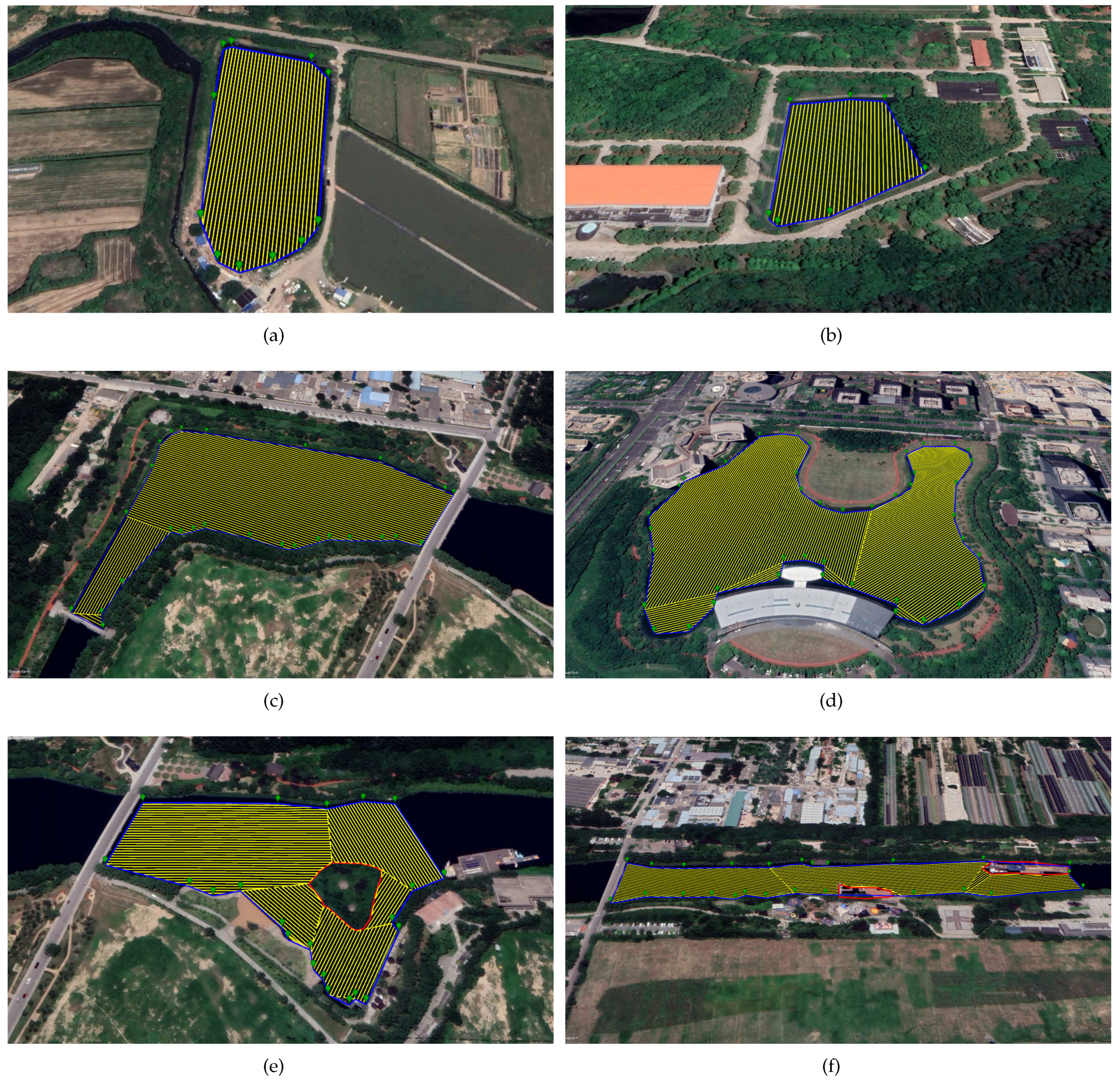
To test our WSCPP method, we set three different kinds of cleaning regions, (1) convex polygons without obstacles inside, (2) concave polygons without obstacles inside, and (3) concave polygons with obstacles inside. For each kind, we set two regions. The generated coverage paths are shown in Figure 9. As can be seen, the proposed method works well in different kinds of regions.

5.2. Trajectory Tracking Evaluation

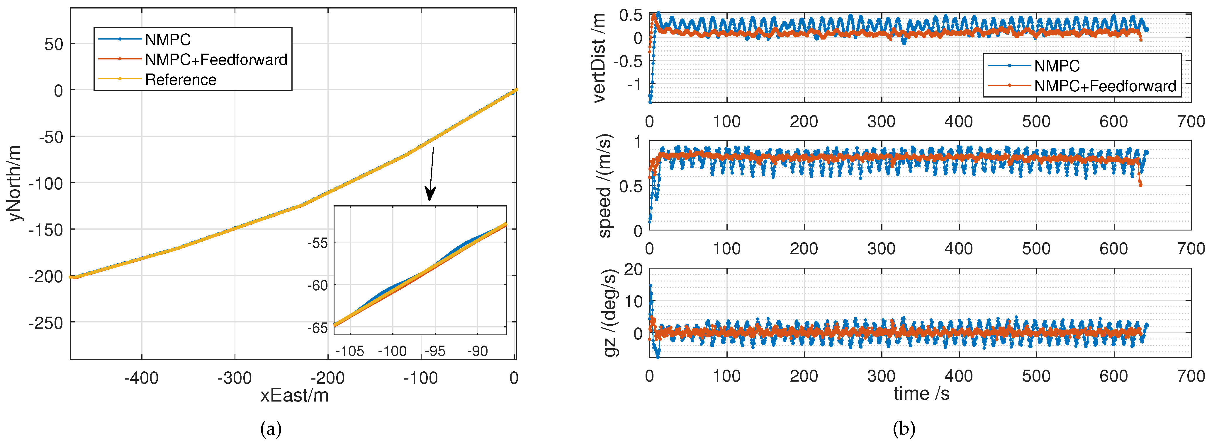
The improved NMPC is responsible for tracking the obstacle-free trajectory from the planner. Compared with the traditional NMPC, our system has higher robust stability. Due to the influence of water flow and trash inside the container, SMURF’s straight yaw angular speed is 1.5°/s. Figure 10 compares the effects of the two control methods. The parameters used to implement the NMPC algorithm are listed as follows: sampling interval: δ = 0.2 s; prediction time horizon: T = 4 s; weighting matrix: Q ˜ = diag { 20 , 20 , 5 , 0.001 , 0.001 , 0.001 } , R ˜ = diag { 1 , 1 , 1 , 1 } , Q ˜ N = diag { 20 , 20 , 5 , 0.001 , 0.001 , 0.001 } . We use the Sequential Quadratic Programming (SQP) algorithm to solve the nonlinear programming problem. The numerical Runge–Kutta (RKF4) method is adopted to calculate the distributed force and torque controller. The controller is implemented in a mini-computer as described in Section 3.2, and the computation time needed to determine the next control action is always below 30 ms. It can be seen that the traditional method is not very good at restraining the hull yaw, and an s-shaped path appears. The new method reduces the average control error from 0.241 m to 0.096 m, and reduces the average angular velocity from 2.029 deg/s to 0.561 deg/s. Because the operation is more stable, the speed loss due to deflection during the hull operation is also reduced. The new method increases the average speed from 0.787 m/s to 0.808 m/s and greatly improves the overall control performance (Figure 10). Considering the strong wind, waves, and different yaw conditions, the robot path tracking under full-load yaw conditions is used to verify the control performance. Experiments with different curvatures are designed, and the result is shown in Figure 11. Figure 11a is the case of broken line walking, and Figure 11b is the case of curve walking. It can be seen from Figure 11a that with our method (with the maximum yaw angular velocity of 6°/s as the control boundary), the robot can still move straight along the desired route. However, there will be a stability error of around 0.4m, which is negligible for robotic tasks. Figure 11b shows that, under the condition of maximum load, our method can effectively suppress the yaw effect caused by environmental disturbance and model changes.

5.3. Water Surface Cleaning Performance Evaluation

In addition, to evaluate the performance of our global path planning method and improved NMPC, we also evaluate the real-world water surface cleaning performance of SMURF.
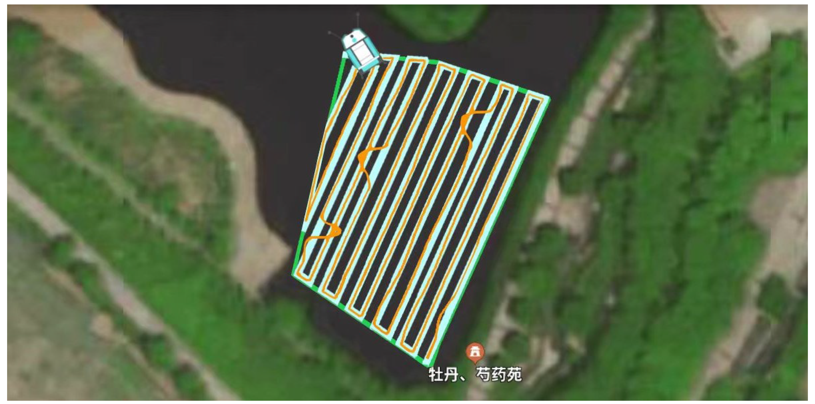
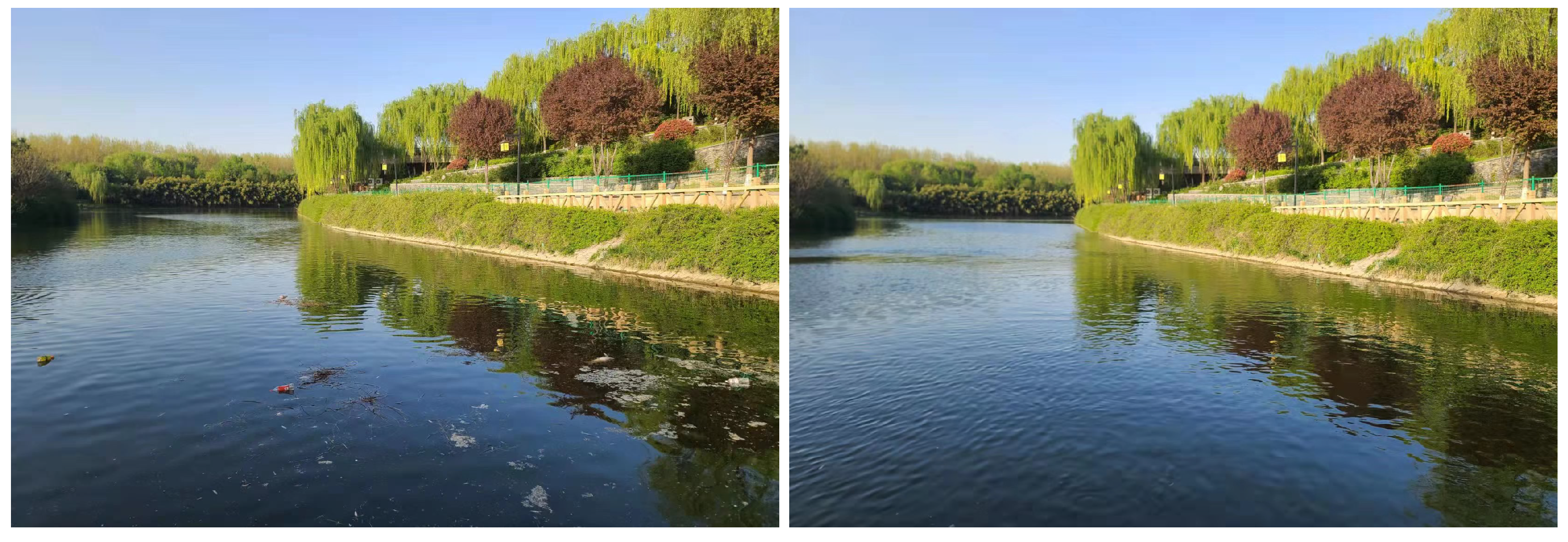
In the experiment, we set a cleaning area of about 4000 m 2 . The average speed of SMURF is 1.2 m/s. It costs about 20 minutes to clean the area. The generated coverage cleaning path and the final trajectory that the SMURF sailed along are shown in Figure 12. As can be seen, after setting an area for cleaning, the SMURF can plan a global coverage path and sail along the path. When wastes are detected during a cleaning task, the SMURF plans a local path and then gets off the global path to collect the waste. The comparison before and after using a SMURF for cleaning is shown in Figure 13. As can be seen, the water surface can be cleaned thoroughly. In addition, we have done a manual cleaning experiment for comparison. The result shows that, in the same cleaning area and with the same waste volume, an experienced human operator takes about 2 h to clean the water surfaces. Compared to traditional manual operation, the SMURF can markedly increase cleaning efficiency. Besides, we have also put SMURFs in different types of water bodies including inland waterways, lakes, and coastal areas under various weather conditions as shown in Figure 14. The SMURF works well in different water bodies for cleaning and resists force 3 wind, meeting the requirements to run regularly in real-world application scenes.

6. Conclusions

In this paper, we designed a novel autonomous water surface waste cleaning robot, SMURF, which can replace humans for surface cleaning. Considering the characteristics of the surface cleaning tasks, we proposed a novel WSCPP method for water surface cleaning, which can be used in areas with irregular boundaries and obstacles inside. Additionally, we designed an improved NMPC for the robots to better track the given path. Finally, we conducted real-world water surface cleaning experiments using the SMURF. The result shows that the cleaning robot can clean up the water surfaces efficiently, and the SMURF works well in various water bodies.

Author Contributions

Conceptualization, J.Z., Y.Y. and Y.C.; methodology, J.Z. and Y.Y.; validation, J.Z.; data curation, J.Z.; coding and experiments, Y.C.; writing—original draft preparation, J.Z. and Y.C.; writing—review and editing, Y.Y. All authors have read and agreed to the published version of the manuscript.

Funding

This work was funded by National Natural Science Foundation of China under Grant Number 11974286.

Institutional Review Board Statement

Not applicable.

Informed Consent Statement

Not applicable.

Data Availability Statement

Not applicable.

Conflicts of Interest

The authors declare no conflict of interest.

Abbreviations

The following abbreviations are used in this manuscript:
CPPCoverage Path Planning
GNSSGlobal Navigation Satellite System
IMUInertial Measurement Unit
mmWaveMillimeter Wave Radar
NMPCNonlinear Model Predictive Controller
USVUnmanned Surface Vehicle
UAVUnmanned Aerial Vehicles
WSCPPWater Surface Coverage Path Planning
RTKReal-Time Kinematic

References

  1. LI, W.C.; Tse, H.; Fok, L. Plastic waste in the marine environment: A review of sources, occurrence and effects. Sci. Total Environ. 2016, 566, 333–349. [Google Scholar] [CrossRef] [PubMed]
  2. Topouzelis, K.; Papakonstantinou, A.; Garaba, S.P. Detection of floating plastics from satellite and unmanned aerial systems (Plastic Litter Project 2018). Int. J. Appl. Earth Observ. Geoinf. 2019, 79, 175–183. [Google Scholar] [CrossRef]
  3. Compa, M.; March, D.; Deudero, S. Spatio-temporal monitoring of coastal floating marine debris in the Balearic Islands from sea-cleaning boats. Mar. Poll. Bull. 2019, 141, 205–214. [Google Scholar] [CrossRef] [PubMed]
  4. Themistocleous, K.; Papoutsa, C.; Michaelides, S.; Hadjimitsis, D. Investigating Detection of Floating Plastic Litter from Space Using Sentinel-2 Imagery. Remote Sens. 2020, 12, 2648. [Google Scholar] [CrossRef]
  5. Cheng, Y.; Zhu, J.; Jiang, M.; Fu, J.; Pang, C.; Wang, P.; Sankaran, K.; Onabola, O.; Liu, Y.; Liu, D.; et al. FloW: A Dataset and Benchmark for Floating Waste Detection in Inland Waters. In Proceedings of the Proceedings of the IEEE/CVF International Conference on Computer Vision, Montreal, QC, Canada, 11–17 October 2021; pp. 10953–10962. [Google Scholar]
  6. Jambeck, J.R.; Geyer, R.; Wilcox, C.; Siegler, T.R.; Perryman, M.; Andrady, A.; Narayan, R.; Law, K.L. Plastic waste inputs from land into the ocean. Science 2015, 347, 768–771. [Google Scholar] [CrossRef] [PubMed]
  7. Lebreton, L.C.; Van Der Zwet, J.; Damsteeg, J.W.; Slat, B.; Andrady, A.; Reisser, J. River plastic emissions to the world’s oceans. Nat. Commun. 2017, 8, 1–10. [Google Scholar] [CrossRef] [Green Version]
  8. Helinski, O.K.; Poor, C.J.; Wolfand, J.M. Ridding our rivers of plastic: A framework for plastic pollution capture device selection. Mar. Poll. Bull. 2021, 165, 112095. [Google Scholar] [CrossRef]
  9. Sanda, B.Y.; Ibrahim, I. Cauces, Categories and Control of Water Pollution. Int. J. Sci. Eng. Sci. 2020, 4, 84–90. [Google Scholar]
  10. Choset, H.; Pignon, P. Coverage path planning: The boustrophedon cellular decomposition. In Proceedings of the Field and Service Robotics; Springer: Berlin/Heidelberg, Germany, 1998; pp. 203–209. [Google Scholar]
  11. Huang, W.H. Optimal line-sweep-based decompositions for coverage algorithms. In Proceedings of the Proceedings 2001 ICRA. IEEE International Conference on Robotics and Automation (Cat. No. 01CH37164), Seoul, Korea, 21–26 May 2001; Volume 1, pp. 27–32. [Google Scholar]
  12. Wang, W.; Gheneti, B.; Mateos, L.A.; Duarte, F.; Ratti, C.; Rus, D. Roboat: An autonomous surface vehicle for urban waterways. In Proceedings of the 2019 IEEE/RSJ International Conference on Intelligent Robots and Systems (IROS), Venetian Macao, Macau, 3–8 November 2019; pp. 6340–6347. [Google Scholar]
  13. Peng, Y.; Yang, Y.; Cui, J.; Li, X.; Pu, H.; Gu, J.; Xie, S.; Luo, J. Development of the USV ‘JingHai-I’and sea trials in the Southern Yellow Sea. Ocean Eng. 2017, 131, 186–196. [Google Scholar] [CrossRef]
  14. Al Maawali, W.; Al Naabi, A.; Al Yaruubi, M.; Saleem, A.; Al Maashri, A. Design and implementation of an unmanned surface vehicle for oil spill handling. In Proceedings of the 2019 1st International Conference on Unmanned Vehicle Systems-Oman (UVS), Muscat, Oman, 5–7 February 2019; pp. 1–6. [Google Scholar]
  15. Shojaei, A.; Moud, H.I.; Flood, I. Proof of concept for the use of small unmanned surface vehicle in built environment management. In Proceedings of the Proceeding of Construction Research Congress, New Orleans, LA, USA, 2–4 April 2018; pp. 148–157. [Google Scholar]
  16. Sinha, A.; Bhardwaj, P.; Vaibhav, B.; Mohommad, N. Research and development of Ro-boat: An autonomous river cleaning robot. In Proceedings of the Intelligent Robots and Computer Vision XXXI: Algorithms and Techniques, San Francisco, CA, USA, 4–6 February 2014; Volume 9025, pp. 195–202. [Google Scholar]
  17. Ruangpayoongsak, N.; Sumroengrit, J.; Leanglum, M. A floating waste scooper robot on water surface. In Proceedings of the 2017 17th International Conference on Control, Automation and Systems (ICCAS), Ramada Plaza, Jeju, Korea, 18–21 October 2017; pp. 1543–1548. [Google Scholar]
  18. Hasany, S.N.; Zaidi, S.S.; Sohail, S.A.; Farhan, M. An autonomous robotic system for collecting garbage over small water bodies. In Proceedings of the 2021 6th International Conference on Automation, Control and Robotics Engineering (CACRE), Dalian, China, 15–17 July 2021; pp. 81–86. [Google Scholar]
  19. Hari, S.S.; Rahul, R.; Prabhu, H.U.; Balasubramanian, V. Android Application Controlled Water Trash Bot Using Internet Of Things. In Proceedings of the 2021 7th International Conference on Electrical Energy Systems (ICEES), Nadu, India, 11 February 2021; pp. 538–542. [Google Scholar]
  20. Chang, H.C.; Hsu, Y.L.; Hung, S.S.; Ou, G.R.; Wu, J.R.; Hsu, C. Autonomous Water Quality Monitoring and Water Surface Cleaning for Unmanned Surface Vehicle. Sensors 2021, 21, 1102. [Google Scholar] [CrossRef]
  21. Cabreira, T.M.; Brisolara, L.B.; Paulo R, F.J. Survey on coverage path planning with unmanned aerial vehicles. Drones 2019, 3, 4. [Google Scholar] [CrossRef]
  22. Cabreira, T.M.; Di Franco, C.; Ferreira, P.R.; Buttazzo, G.C. Energy-aware spiral coverage path planning for uav photogrammetric applications. IEEE Robot. Autom. Lett. 2018, 3, 3662–3668. [Google Scholar] [CrossRef]
  23. Coombes, M.; Fletcher, T.; Chen, W.H.; Liu, C. Optimal polygon decomposition for UAV survey coverage path planning in wind. Sensors 2018, 18, 2132. [Google Scholar] [CrossRef] [PubMed] [Green Version]
  24. Chen, J.; Du, C.; Zhang, Y.; Han, P.; Wei, W. A clustering-based coverage path planning method for autonomous heterogeneous UAVs. IEEE Trans. Intell. Transp. Syst. 2021. [Google Scholar] [CrossRef]
  25. Hameed, I.; Bochtis, D.; Sørensen, C.; Jensen, A.; Larsen, R. Optimized driving direction based on a three-dimensional field representation. Comput. Electron. Agric. 2013, 91, 145–153. [Google Scholar] [CrossRef]
  26. Yu, X.; Roppel, T.A.; Hung, J.Y. An optimization approach for planning robotic field coverage. In Proceedings of the IECON 2015-41st Annual Conference of the IEEE Industrial Electronics Society, Yokohama, Japan, 9–12 November 2015; pp. 004032–004039. [Google Scholar]
  27. Jeon, C.W.; Kim, H.J.; Yun, C.; Han, X.; Kim, J.H. Design and validation testing of a complete paddy field-coverage path planner for a fully autonomous tillage tractor. Biosyst. Eng. 2021, 208, 79–97. [Google Scholar] [CrossRef]
  28. Mao, Y.; Dou, L.; Chen, J.; Fang, H.; Zhang, H.; Cao, H. Combined complete coverage path planning for autonomous mobile robot in indoor environment. In Proceedings of the 2009 7th Asian Control Conference, Hong Kong, 27–29 August 2009; pp. 1468–1473. [Google Scholar]
  29. Bormann, R.; Jordan, F.; Hampp, J.; Hägele, M. Indoor coverage path planning: Survey, implementation, analysis. In Proceedings of the 2018 IEEE International Conference on Robotics and Automation (ICRA), Brisbane, Australia, 21–25 May 2018; pp. 1718–1725. [Google Scholar]
  30. Kyaw, P.T.; Paing, A.; Thu, T.T.; Mohan, R.E.; Le, A.V.; Veerajagadheswar, P. Coverage path planning for decomposition reconfigurable grid-maps using deep reinforcement learning based travelling salesman problem. IEEE Access 2020, 8, 225945–225956. [Google Scholar] [CrossRef]
  31. Xu, P.F.; Ding, Y.X.; Luo, J.C. Complete Coverage Path Planning of an Unmanned Surface Vehicle Based on a Complete Coverage Neural Network Algorithm. J. Mar. Sci. Eng. 2021, 9, 1163. [Google Scholar] [CrossRef]
  32. Zhang, Q.; Li, C.; Lu, X.; Huang, S. Research on complete coverage path planning for unmanned surface vessel. In Proceedings of the IOP Conference Series: Earth and Environmental Science, Moscow, Russia, 27 May–6 June 2019; Volume 300, p. 022037. [Google Scholar]
  33. Duchoň, F.; Babinec, A.; Kajan, M.; Beňo, P.; Florek, M.; Fico, T.; Jurišica, L. Path planning with modified a star algorithm for a mobile robot. Procedia Eng. 2014, 96, 59–69. [Google Scholar] [CrossRef] [Green Version]
  34. Cheng, Y.; Xu, H.; Liu, Y. Robust Small Object Detection on the Water Surface Through Fusion of Camera and Millimeter Wave Radar. In Proceedings of the IEEE/CVF International Conference on Computer Vision, Montreal, QC, Canada, 10–17 October 2021; pp. 15263–15272. [Google Scholar]
  35. Lee, D.T.; Schachter, B.J. Two algorithms for constructing a Delaunay triangulation. Int. J. Comput. Inf. Sci. 1980, 9, 219–242. [Google Scholar] [CrossRef]
  36. Fossen, T.I. A nonlinear unified state-space model for ship maneuvering and control in a seaway. Int. J. Bifurc. Chaos 2005, 15, 2717–2746. [Google Scholar] [CrossRef]
Figure 1. The floating wastes in oceans, coastal areas, and inland waters.
Jmse 10 01620 g001
Figure 2. Examples of cleaning water surfaces manually.
Jmse 10 01620 g002
Figure 3. Mechanical design of SMURF.
Jmse 10 01620 g003
Figure 4. Working procedure of SMURF.
Jmse 10 01620 g004
Figure 5. Autonomous system design of SMURF.
Jmse 10 01620 g005
Figure 6. Illustration of trash collection during coverage path tracking.
Jmse 10 01620 g006
Figure 7. Schematic diagram of the area to be cleaned S and the obstacle area A.
Jmse 10 01620 g007
Figure 8. Framework of the improved NMPC controller.
Jmse 10 01620 g008
Figure 9. Result of WSCPP in different kinds of regions. The blue lines and the green points mark the region border. The red lines mark the obstacles border. The yellow lines mark the generated coverage path.
Jmse 10 01620 g009
Figure 10. Comparison between the NMPC and the improved NMPC. (a) Path tracking performance of two methods and the reference. (b) Average control error, average velocity, and average angular velocity of the two methods.
Jmse 10 01620 g010
Figure 11. Comparison of path tracking results of NMPC and improved NMPC under full load conditions.
Jmse 10 01620 g011
Figure 12. The cleaning boundary (green line), global coverage cleaning path (blue line) generated by SMURF, and the real trajectory of SMURF (orange line) during cleaning.
Jmse 10 01620 g012
Figure 13. Comparison of water surface cleanliness before and after using a SMURF to clean autonomously.
Jmse 10 01620 g013
Figure 14. SMURFs used in various water bodies and weather conditions for water surface cleaning.
Jmse 10 01620 g014
Table 1. Technical specifications of SMURF.
ItemsCharacteristics
Length × Height × Width2.5 m × 1.6 m × 0.8 m
Weight100 kg
Trash Payload40 kg
Maximum Speed1.6 m/s
Height of Center of Gravity0.25 m
Table 2. Hardware system of SMURF.
ItemsCharacteristics
Main processorNvidia Xavier NX
SensorRGB camera, mmWave radar, GNSS, IMU
Power Supply24 V 140 AH lithium battery
Control ModeAutomatic / 2.4 G Wireless / 4 G Network
Running Time8 h
Publisher’s Note: MDPI stays neutral with regard to jurisdictional claims in published maps and institutional affiliations.